Embed Size (px)
Citation preview
Created: 2021-02-10 17:08:21Project-Task No. 03002001-0003
MPR Associates, Inc.320 King St. • Alexandria, VA 22314(703) 519-0200 • www.mpr.com
0300-0003-RPT-001Revision 1
Impact of Tertiary Creep on Time DependentAllowable Stresses for Type 304H and 316HStainless SteelsPrepared for: Argonne National Laboratory
Preparer: Thomas Dabrow E-signed by: Thomas Dabrowon 2021-02-10 17:08:21
Preparer: James Nestell Jr E-signed by: James Nestell Jron 2021-02-11 13:12:25
Reviewer: Valentina Angelici E-signed by: Valentina Angelicion 2021-02-10 17:10:26
Approver: Valentina Angelici E-signed by: Valentina Angelicion 2021-02-12 14:27:10
QA Statement of ComplianceThis document has been prepared, reviewed, and approved in accordance with the Quality Assurance requirements of theMPR Standard Quality Program.
Page 2 of 290300-0003-RPT-001 Revision 1
Impact of Tertiary Creep on Time Dependent Allowable Stresses for Type 304H and 316H Stainless Steels
RECORD OF REVISIONS
Revision Number
Pages /Sections Revised
Revision Description
0
1
All
25
Initial Release
Updated Coefficients in Equation 9
Page 3 of 290300-0003-RPT-001 Revision 1
Table of Contents
1.0 Introduction ........................................................................................................... 5
2.0 Allowable Stresses in the ASME Code...................................................................... 6 2.1. Current Issue with the Tertiary Creep Criterion ......................................................6
2.2. Tertiary Creep Measurements ..................................................................................7
2.3. ASME Efforts to Develop and Apply the Criterion ...............................................13
3.0 Options for Path Forward ................................................................................ 18 3.1. Option 2-Leveraged Data Regression ....................................................................19
4.0 Conclusions and Recommendations .............................................................. 27
5.0 References ........................................................................................................ 29
Tables
Table 2-1-1 Impact of Tertiary Creep on Allowable Stresses (in MPa) for Type 316H Stainless Steels ........................................................................................................................7
Table 3-1.1-1 Time to rupture metric (hours, Kelvin, MPa) regression coefficients for 304H and 316H Stainless Steel (Reference 1) .................................................................24
Table 3.1.2-2 St Values (MPa) for type 304SS. Blue cells are controlled by S1%, orange cells are controlled by Sr, and yellow cells are controlled by St3. ..................................27
Figures
Figure 2.2.1-1(a). Time to Rupture vs. Time to Onset of Tertiary Creep for Type 304 Stainless Steel (Reference 3) ...................................................................................9
Figure 2.2.1-1(b). Time to Rupture vs. Time to Onset of Tertiary Creep for Type 316 Stainless Steel (Reference 3) .................................................................................10
Figure 2.2.1-3 Creep Curve for Type 316 Stainless Steel with Two Creep Rate Minima (Reference 8, arrows added) ..................................................................................12
Figure 2.2.1-4 Time to Onset of Tertiary Creep vs Time to Rupture Showing Effect of Non-Classical Creep Curves for Type 316 Stainless Steel (Reference 5) .....................12
Page 4 of 290300-0003-RPT-001 Revision 1
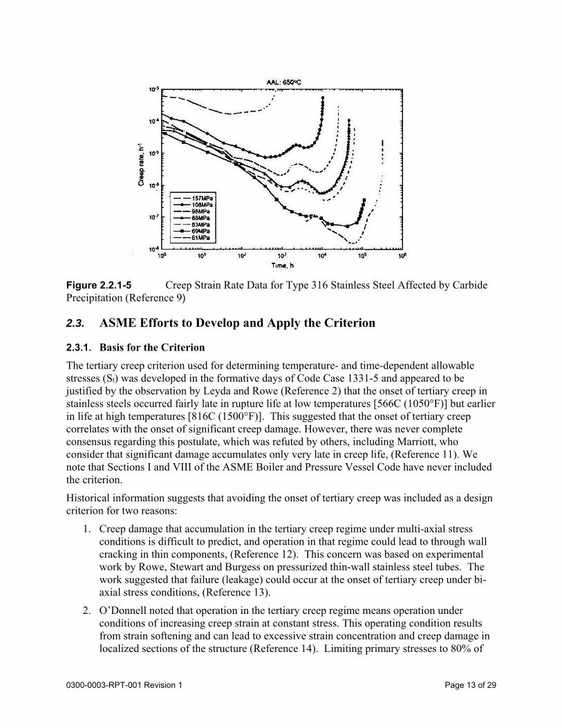
Figure 2.2.1-5 Creep Strain Rate Data for Type 316 Stainless Steel Affected by Carbide Precipitation (Reference 10) ..................................................................................13
Figure 3.1.1-1 Time to Onset of Tertiary Creep versus Time to Rupture for 316H Stainless Steel........................................................................................................................20
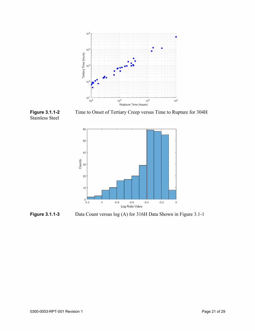
Figure 3.1.1-2 Time to Onset of Tertiary Creep versus Time to Rupture for 304H Stainless Steel........................................................................................................................21
Figure 3.1.1-3 Data Count versus Log (A) for 316H Data Shown in Figure 3.1-1 ......................21
Figure 3.1.1-4 Data Count versus Log (A) for 304H Data Shown in Figure 3.1-2 ......................22
Figure 3.1.1-5 Time-to-Rupture Regression for Type 316H Stainless Steel (Reference 1) .........23
Figure 3.1.1-6 Time-to-Rupture for Type 304H Stainless Steel (Reference 1) ............................24
Page 5 of 290300-0003-RPT-001 Revision 1
1.0 Introduction
The U.S. Department of Energy (DOE) has established a program to develop the next generation of nuclear reactors (Generation IV), which include high-temperature gas-cooled and liquid-cooled reactors. One of the challenges identified by this program was the development of necessary codes and standards to support the design and construction of the new reactors. The current elevated temperature allowable stresses are limited to 300,000 hours, which is sufficient for a 40-year design life. As a part of the Generation IV program, the allowable stress values in Section III of the ASME code are being revised for Type 304 and 316 stainless steel (SS) to extend the design life from 300,000 to 500,000 (60-year lifetime) in the ASME BPV Code, Section III, Division 5.
The current allowable stress values for these two materials were developed in the 1970s using a creep database that was significantly smaller than the currently available. The time dependent allowable stress values (St values) in Division 5 are based on creep rupture and time to reach 1% strain. Tertiary creep data then available were very sparse, and computed stresses based on the criterion were not limiting. Today, we can take advantage of the extensive amount of creep data available from Oak Ridge and the Japanese NIMS to recompute allowable stresses based on all three stress criteria.
The allowable stresses for the two stainless steel alloys computed from the expanded databases show a marked reduction in values compared to current code values at moderate to long service times and higher temperatures. This is due, in large part, to the impact of the tertiary creep criterion on the computations.
This paper provides an historical review of the tertiary creep stress criterion as it has been applied to ASME Boiler and Pressure Vessel Code nuclear rules. It describes the early efforts by the industry to measure the time-to-onset of tertiary creep, as well as the original bases for the inclusion of tertiary creep among the time dependent stress criteria. The reasons for the recently calculated low values of allowable time-dependent stresses are described, and a different method to compute stresses that avoids these difficulties is developed. The new method shows the tertiary creep criterion is not limiting for Type 304H and 316H stainless steels.
Page 6 of 290300-0003-RPT-001 Revision 1
2.0 Allowable Stresses in the ASME Code
Section III, Division 5 of the ASME code provides rules for construction of high temperature reactor components, and defines the following design stress intensity limits
St - allowable stress value dependent on time and temperature,
Sm - lowest stress intensity at a given temperature (time independent), and
Smt – the lessor of Sm and St.
Given a temperature and time interval of service, Division 5 requires that the elevated temperature, time dependent allowable stress, St, be calculated based on the lowest of the following three criteria:
100% of the average stress required to obtain a total (elastic, plastic, primary, and secondary creep) strain of 1% (S1%),
80% of the minimum stress to cause the onset of tertiary creep (St3), and
67% of the minimum stress to rupture (Sr).
The first and last of these criteria prevent excessive distortion or creep rupture of the component. The tertiary creep criterion is discussed in the following section.
2.1. Current Issue with the Tertiary Creep Criterion
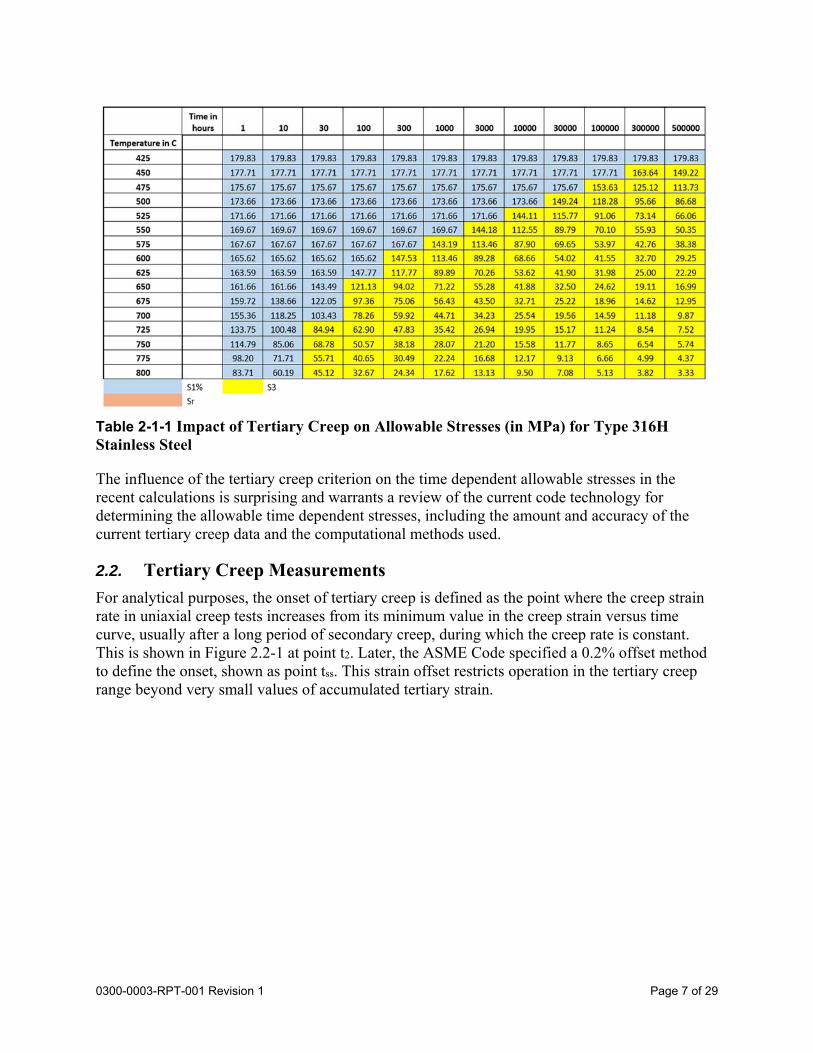
Sengupta and Nestell, Reference 1, computed 500,000-hour allowable stresses for Type 304H and 316H stainless steels for the Generation IV reactor development effort. Current creep databases from Oak Ridge, NIMS and Petten were used to recompute stresses for all times and temperatures in the stress table plus values for 500,000 hours. They found the tertiary creep criterion plays a widespread role limiting allowable stresses, as shown in yellow in Table 2.1-1 below. In the current code these stresses are controlled by the rupture criterion. A similar impact is observed for Type 304H stainless steel, which is discussed in Section 2.3.3. For both alloys, the stresses controlled by tertiary creep are smaller than current code values by up to 45 percent. About half of this effect is due to the tertiary creep regression results and half is due to the apparent lower average rupture strength of materials in modern creep rupture databases.
Page 7 of 290300-0003-RPT-001 Revision 1
Table 2-1-1 Impact of Tertiary Creep on Allowable Stresses (in MPa) for Type 316H Stainless Steel
The influence of the tertiary creep criterion on the time dependent allowable stresses in the recent calculations is surprising and warrants a review of the current code technology for determining the allowable time dependent stresses, including the amount and accuracy of the current tertiary creep data and the computational methods used.
2.2. Tertiary Creep Measurements
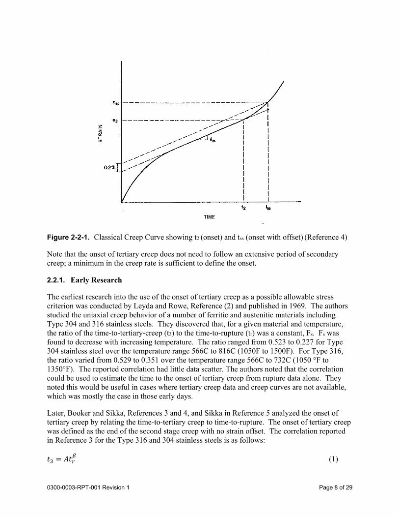
For analytical purposes, the onset of tertiary creep is defined as the point where the creep strain rate in uniaxial creep tests increases from its minimum value in the creep strain versus time curve, usually after a long period of secondary creep, during which the creep rate is constant. This is shown in Figure 2.2-1 at point t2. Later, the ASME Code specified a 0.2% offset method to define the onset, shown as point tss. This strain offset restricts operation in the tertiary creep range beyond very small values of accumulated tertiary strain.
Page 8 of 290300-0003-RPT-001 Revision 1
Figure 2-2-1. Classical Creep Curve showing t2 (onset) and tss (onset with offset) (Reference 4)
Note that the onset of tertiary creep does not need to follow an extensive period of secondary creep; a minimum in the creep rate is sufficient to define the onset.
2.2.1. Early Research
The earliest research into the use of the onset of tertiary creep as a possible allowable stress criterion was conducted by Leyda and Rowe, Reference (2) and published in 1969. The authors studied the uniaxial creep behavior of a number of ferritic and austenitic materials including Type 304 and 316 stainless steels. They discovered that, for a given material and temperature, the ratio of the time-to-tertiary-creep (t3) to the time-to-rupture (tr) was a constant, Fs. Fs was found to decrease with increasing temperature. The ratio ranged from 0.523 to 0.227 for Type 304 stainless steel over the temperature range 566C to 816C (1050F to 1500F). For Type 316, the ratio varied from 0.529 to 0.351 over the temperature range 566C to 732C (1050 °F to 1350°F). The reported correlation had little data scatter. The authors noted that the correlation could be used to estimate the time to the onset of tertiary creep from rupture data alone. They noted this would be useful in cases where tertiary creep data and creep curves are not available, which was mostly the case in those early days.
Later, Booker and Sikka, References 3 and 4, and Sikka in Reference 5 analyzed the onset of tertiary creep by relating the time-to-tertiary creep to time-to-rupture. The onset of tertiary creep was defined as the end of the second stage creep with no strain offset. The correlation reported in Reference 3 for the Type 316 and 304 stainless steels is as follows:
𝑡 𝐴𝑡 (1)
Page 9 of 290300-0003-RPT-001 Revision 1
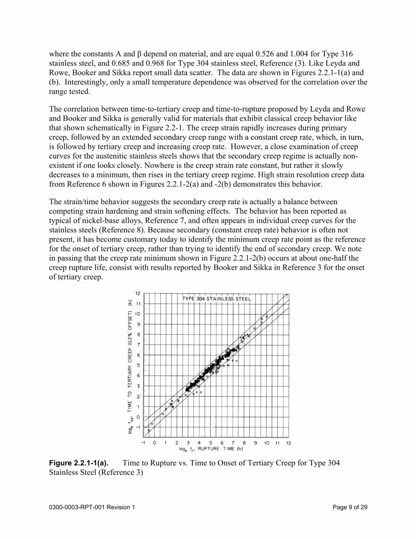
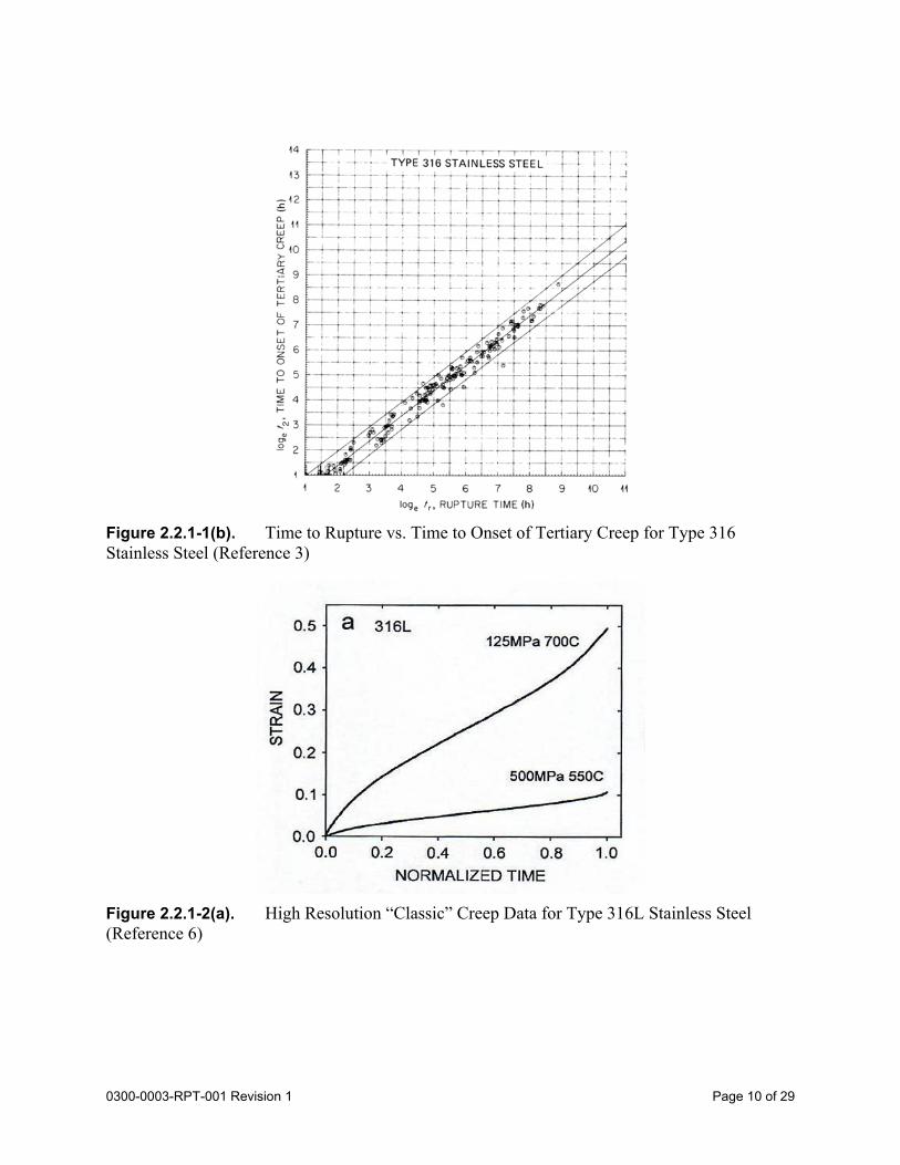
where the constants A and β depend on material, and are equal 0.526 and 1.004 for Type 316 stainless steel, and 0.685 and 0.968 for Type 304 stainless steel, Reference (3). Like Leyda and Rowe, Booker and Sikka report small data scatter. The data are shown in Figures 2.2.1-1(a) and (b). Interestingly, only a small temperature dependence was observed for the correlation over the range tested.
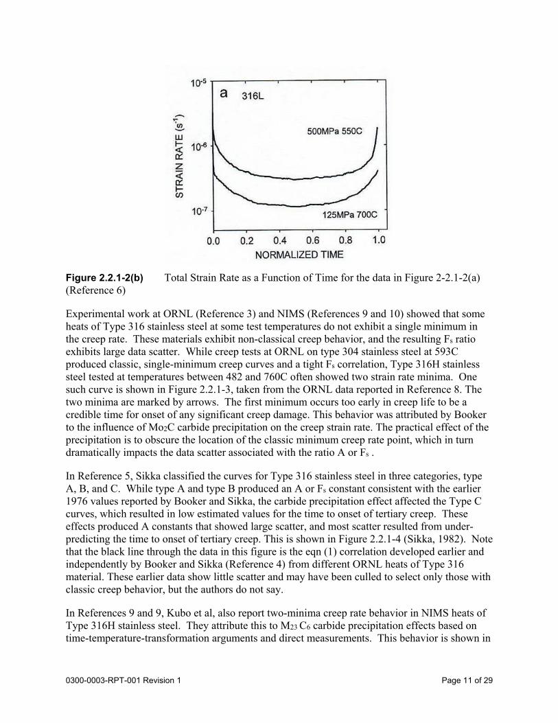
The correlation between time-to-tertiary creep and time-to-rupture proposed by Leyda and Rowe and Booker and Sikka is generally valid for materials that exhibit classical creep behavior like that shown schematically in Figure 2.2-1. The creep strain rapidly increases during primary creep, followed by an extended secondary creep range with a constant creep rate, which, in turn, is followed by tertiary creep and increasing creep rate. However, a close examination of creep curves for the austenitic stainless steels shows that the secondary creep regime is actually non-existent if one looks closely. Nowhere is the creep strain rate constant, but rather it slowly decreases to a minimum, then rises in the tertiary creep regime. High strain resolution creep data from Reference 6 shown in Figures 2.2.1-2(a) and -2(b) demonstrates this behavior.
The strain/time behavior suggests the secondary creep rate is actually a balance between competing strain hardening and strain softening effects. The behavior has been reported as typical of nickel-base alloys, Reference 7, and often appears in individual creep curves for the stainless steels (Reference 8). Because secondary (constant creep rate) behavior is often not present, it has become customary today to identify the minimum creep rate point as the reference for the onset of tertiary creep, rather than trying to identify the end of secondary creep. We note in passing that the creep rate minimum shown in Figure 2.2.1-2(b) occurs at about one-half the creep rupture life, consist with results reported by Booker and Sikka in Reference 3 for the onset of tertiary creep.
Figure 2.2.1-1(a). Time to Rupture vs. Time to Onset of Tertiary Creep for Type 304 Stainless Steel (Reference 3)
Page 10 of 290300-0003-RPT-001 Revision 1
Figure 2.2.1-1(b). Time to Rupture vs. Time to Onset of Tertiary Creep for Type 316 Stainless Steel (Reference 3)
Figure 2.2.1-2(a). High Resolution “Classic” Creep Data for Type 316L Stainless Steel (Reference 6)
Page 11 of 290300-0003-RPT-001 Revision 1
Figure 2.2.1-2(b) Total Strain Rate as a Function of Time for the data in Figure 2-2.1-2(a) (Reference 6)
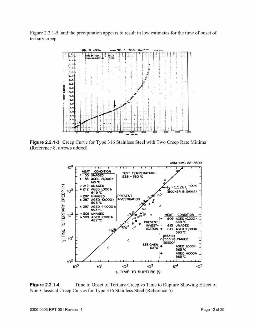
Experimental work at ORNL (Reference 3) and NIMS (References 9 and 10) showed that some heats of Type 316 stainless steel at some test temperatures do not exhibit a single minimum in the creep rate. These materials exhibit non-classical creep behavior, and the resulting Fs ratio exhibits large data scatter. While creep tests at ORNL on type 304 stainless steel at 593C produced classic, single-minimum creep curves and a tight Fs correlation, Type 316H stainless steel tested at temperatures between 482 and 760C often showed two strain rate minima. One such curve is shown in Figure 2.2.1-3, taken from the ORNL data reported in Reference 8. The two minima are marked by arrows. The first minimum occurs too early in creep life to be a credible time for onset of any significant creep damage. This behavior was attributed by Booker to the influence of Mo2C carbide precipitation on the creep strain rate. The practical effect of the precipitation is to obscure the location of the classic minimum creep rate point, which in turn dramatically impacts the data scatter associated with the ratio A or Fs .
In Reference 5, Sikka classified the curves for Type 316 stainless steel in three categories, type A, B, and C. While type A and type B produced an A or Fs constant consistent with the earlier 1976 values reported by Booker and Sikka, the carbide precipitation effect affected the Type C curves, which resulted in low estimated values for the time to onset of tertiary creep. These effects produced A constants that showed large scatter, and most scatter resulted from under-predicting the time to onset of tertiary creep. This is shown in Figure 2.2.1-4 (Sikka, 1982). Note that the black line through the data in this figure is the eqn (1) correlation developed earlier and independently by Booker and Sikka (Reference 4) from different ORNL heats of Type 316 material. These earlier data show little scatter and may have been culled to select only those with classic creep behavior, but the authors do not say.
In References 9 and 9, Kubo et al, also report two-minima creep rate behavior in NIMS heats of Type 316H stainless steel. They attribute this to M23 C6 carbide precipitation effects based on time-temperature-transformation arguments and direct measurements. This behavior is shown in
Page 12 of 290300-0003-RPT-001 Revision 1
Figure 2.2.1-5, and the precipitation appears to result in low estimates for the time of onset of tertiary creep.
Figure 2.2.1-3 Creep Curve for Type 316 Stainless Steel with Two Creep Rate Minima (Reference 8, arrows added)
Figure 2.2.1-4 Time to Onset of Tertiary Creep vs Time to Rupture Showing Effect of Non-Classical Creep Curves for Type 316 Stainless Steel (Reference 5)
Page 13 of 290300-0003-RPT-001 Revision 1
Figure 2.2.1-5 Creep Strain Rate Data for Type 316 Stainless Steel Affected by Carbide Precipitation (Reference 9)
2.3. ASME Efforts to Develop and Apply the Criterion
2.3.1. Basis for the Criterion
The tertiary creep criterion used for determining temperature- and time-dependent allowable stresses (St) was developed in the formative days of Code Case 1331-5 and appeared to be justified by the observation by Leyda and Rowe (Reference 2) that the onset of tertiary creep in stainless steels occurred fairly late in rupture life at low temperatures [566C (1050°F)] but earlier in life at high temperatures [816C (1500°F)]. This suggested that the onset of tertiary creep correlates with the onset of significant creep damage. However, there was never complete consensus regarding this postulate, which was refuted by others, including Marriott, who consider that significant damage accumulates only very late in creep life, (Reference 11). We note that Sections I and VIII of the ASME Boiler and Pressure Vessel Code have never included the criterion.
Historical information suggests that avoiding the onset of tertiary creep was included as a design criterion for two reasons:
1. Creep damage that accumulation in the tertiary creep regime under multi-axial stress conditions is difficult to predict, and operation in that regime could lead to through wall cracking in thin components, (Reference 12). This concern was based on experimental work by Rowe, Stewart and Burgess on pressurized thin-wall stainless steel tubes. The work suggested that failure (leakage) could occur at the onset of tertiary creep under bi-axial stress conditions, (Reference 13).
2. O’Donnell noted that operation in the tertiary creep regime means operation under conditions of increasing creep strain at constant stress. This operating condition results from strain softening and can lead to excessive strain concentration and creep damage in localized sections of the structure (Reference 14). Limiting primary stresses to 80% of
Page 14 of 290300-0003-RPT-001 Revision 1
the stress required to produce 0.2% tertiary strain (the offset) prevents operation deep into the tertiary creep regime.
Based on these arguments, the ASME Code Case Committee for code case N-1331 took actions to set primary stress limits to preclude operation in the third stage (tertiary) creep regime. Apparently the criterion never actually impacted the code allowable stresses for the stainless steels, because, as Swindeman recently reported (Reference 15), the original meeting minutes revealed that the tertiary creep criterion was not found to be limiting compared to the 1% strain and rupture criteria. We thus conclude that current Division 5 allowable stresses for Type 304H and 316H steels are determined by the 1% strain and rupture criteria alone, since no major revision to the Division 5 allowable stress tables for the stainless steels has been performed since the original compilation.
2.3.2. Recent Efforts to Apply the Criterion – Swindeman
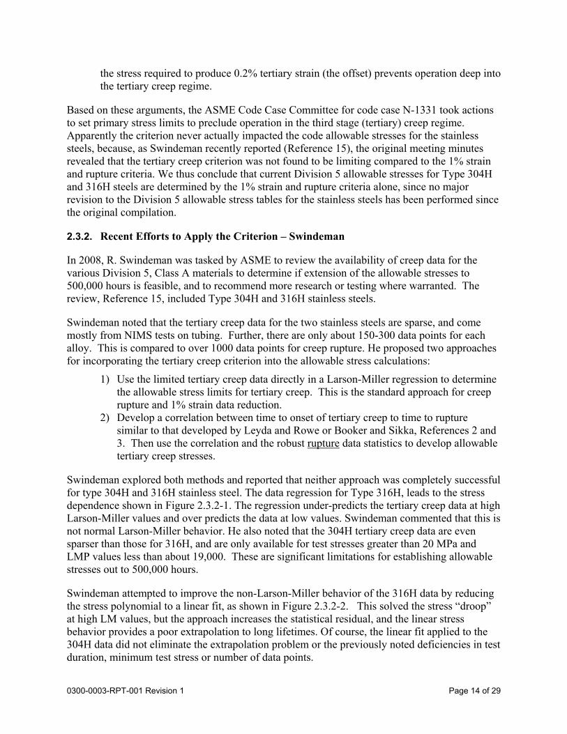
In 2008, R. Swindeman was tasked by ASME to review the availability of creep data for the various Division 5, Class A materials to determine if extension of the allowable stresses to 500,000 hours is feasible, and to recommend more research or testing where warranted. The review, Reference 15, included Type 304H and 316H stainless steels.
Swindeman noted that the tertiary creep data for the two stainless steels are sparse, and come mostly from NIMS tests on tubing. Further, there are only about 150-300 data points for each alloy. This is compared to over 1000 data points for creep rupture. He proposed two approaches for incorporating the tertiary creep criterion into the allowable stress calculations:
1) Use the limited tertiary creep data directly in a Larson-Miller regression to determine the allowable stress limits for tertiary creep. This is the standard approach for creep rupture and 1% strain data reduction.
2) Develop a correlation between time to onset of tertiary creep to time to rupture similar to that developed by Leyda and Rowe or Booker and Sikka, References 2 and 3. Then use the correlation and the robust rupture data statistics to develop allowable tertiary creep stresses.
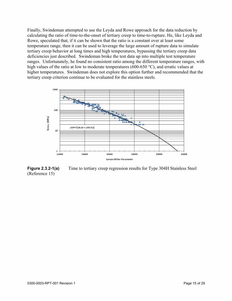
Swindeman explored both methods and reported that neither approach was completely successful for type 304H and 316H stainless steel. The data regression for Type 316H, leads to the stress dependence shown in Figure 2.3.2-1. The regression under-predicts the tertiary creep data at high Larson-Miller values and over predicts the data at low values. Swindeman commented that this is not normal Larson-Miller behavior. He also noted that the 304H tertiary creep data are even sparser than those for 316H, and are only available for test stresses greater than 20 MPa and LMP values less than about 19,000. These are significant limitations for establishing allowable stresses out to 500,000 hours.
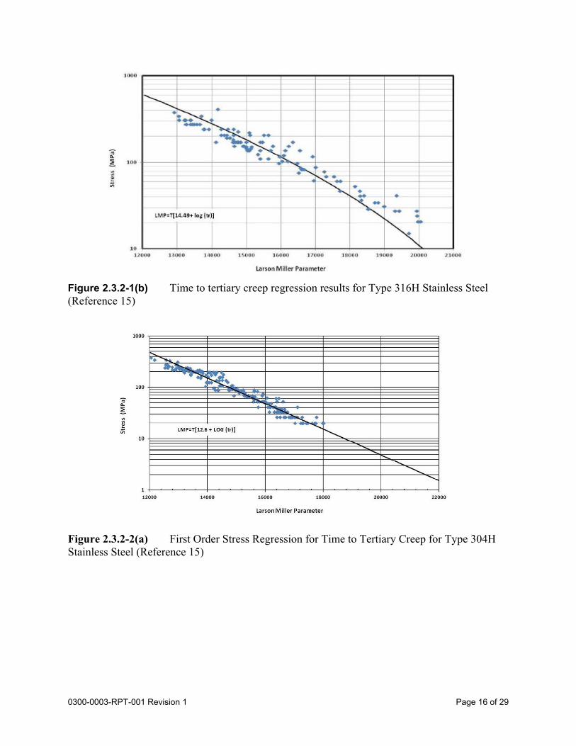
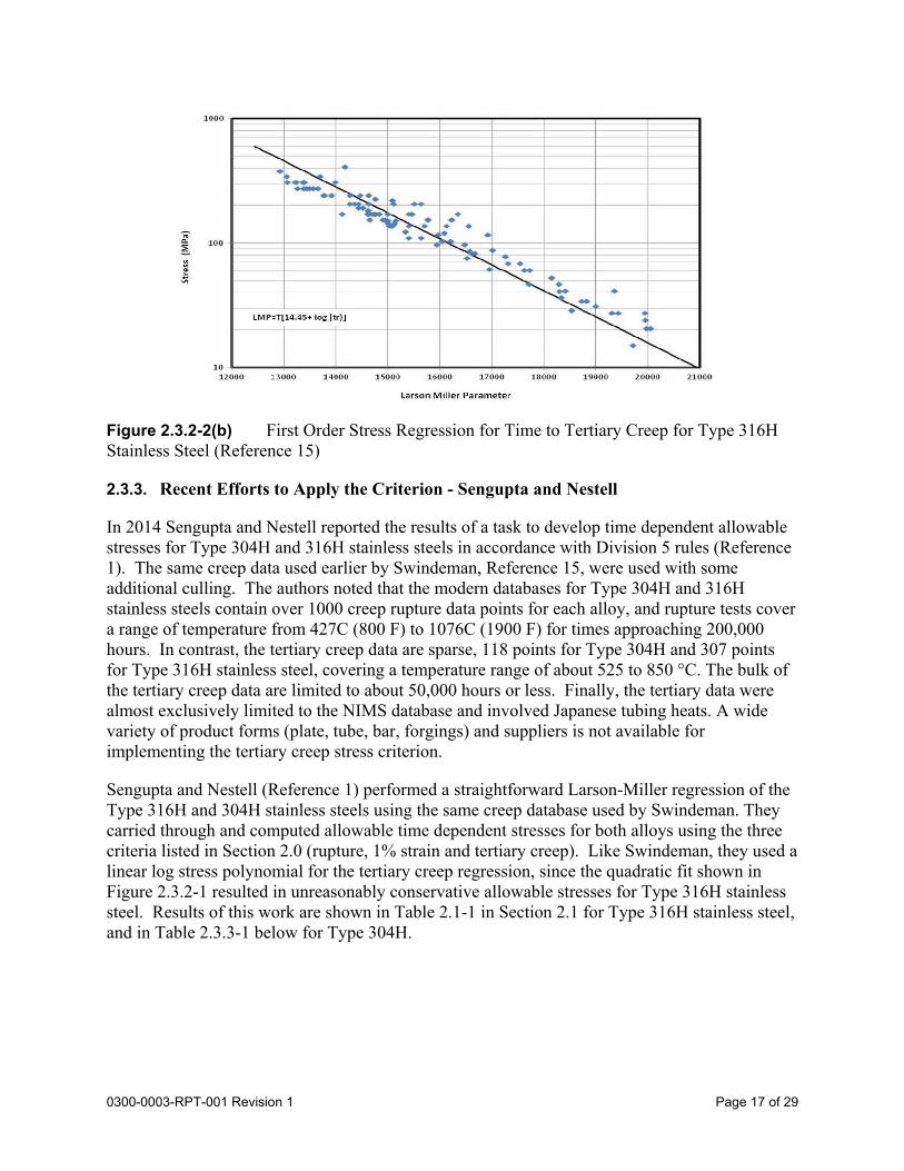
Swindeman attempted to improve the non-Larson-Miller behavior of the 316H data by reducing the stress polynomial to a linear fit, as shown in Figure 2.3.2-2. This solved the stress “droop” at high LM values, but the approach increases the statistical residual, and the linear stress behavior provides a poor extrapolation to long lifetimes. Of course, the linear fit applied to the 304H data did not eliminate the extrapolation problem or the previously noted deficiencies in test duration, minimum test stress or number of data points.
Page 15 of 290300-0003-RPT-001 Revision 1
Finally, Swindeman attempted to use the Leyda and Rowe approach for the data reduction by calculating the ratio of time-to-the-onset of tertiary creep to time-to-rupture. He, like Leyda and Rowe, speculated that, if it can be shown that the ratio is a constant over at least some temperature range, then it can be used to leverage the large amount of rupture data to simulate tertiary creep behavior at long times and high temperatures, bypassing the tertiary creep data deficiencies just described. Swindeman broke the test data up into multiple test temperature ranges. Unfortunately, he found no consistent ratio among the different temperature ranges, with high values of the ratio at low to moderate temperatures (600-650 °C), and erratic values at higher temperatures. Swindeman does not explore this option further and recommended that the tertiary creep criterion continue to be evaluated for the stainless steels.
Figure 2.3.2-1(a) Time to tertiary creep regression results for Type 304H Stainless Steel (Reference 15)
Page 16 of 290300-0003-RPT-001 Revision 1
Figure 2.3.2-1(b) Time to tertiary creep regression results for Type 316H Stainless Steel (Reference 15)
Figure 2.3.2-2(a) First Order Stress Regression for Time to Tertiary Creep for Type 304H Stainless Steel (Reference 15)
Page 17 of 290300-0003-RPT-001 Revision 1
Figure 2.3.2-2(b) First Order Stress Regression for Time to Tertiary Creep for Type 316H Stainless Steel (Reference 15)
2.3.3. Recent Efforts to Apply the Criterion - Sengupta and Nestell
In 2014 Sengupta and Nestell reported the results of a task to develop time dependent allowable stresses for Type 304H and 316H stainless steels in accordance with Division 5 rules (Reference 1). The same creep data used earlier by Swindeman, Reference 15, were used with some additional culling. The authors noted that the modern databases for Type 304H and 316H stainless steels contain over 1000 creep rupture data points for each alloy, and rupture tests cover a range of temperature from 427C (800 F) to 1076C (1900 F) for times approaching 200,000 hours. In contrast, the tertiary creep data are sparse, 118 points for Type 304H and 307 points for Type 316H stainless steel, covering a temperature range of about 525 to 850 °C. The bulk of the tertiary creep data are limited to about 50,000 hours or less. Finally, the tertiary data were almost exclusively limited to the NIMS database and involved Japanese tubing heats. A wide variety of product forms (plate, tube, bar, forgings) and suppliers is not available for implementing the tertiary creep stress criterion.
Sengupta and Nestell (Reference 1) performed a straightforward Larson-Miller regression of the Type 316H and 304H stainless steels using the same creep database used by Swindeman. They carried through and computed allowable time dependent stresses for both alloys using the three criteria listed in Section 2.0 (rupture, 1% strain and tertiary creep). Like Swindeman, they used a linear log stress polynomial for the tertiary creep regression, since the quadratic fit shown in Figure 2.3.2-1 resulted in unreasonably conservative allowable stresses for Type 316H stainless steel. Results of this work are shown in Table 2.1-1 in Section 2.1 for Type 316H stainless steel, and in Table 2.3.3-1 below for Type 304H.
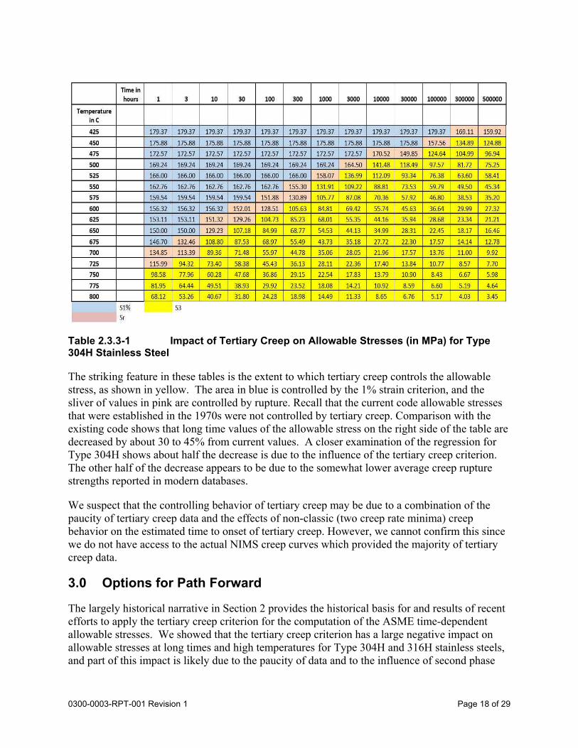
Page 18 of 290300-0003-RPT-001 Revision 1
Table 2.3.3-1 Impact of Tertiary Creep on Allowable Stresses (in MPa) for Type 304H Stainless Steel
The striking feature in these tables is the extent to which tertiary creep controls the allowable stress, as shown in yellow. The area in blue is controlled by the 1% strain criterion, and the sliver of values in pink are controlled by rupture. Recall that the current code allowable stresses that were established in the 1970s were not controlled by tertiary creep. Comparison with the existing code shows that long time values of the allowable stress on the right side of the table are decreased by about 30 to 45% from current values. A closer examination of the regression for Type 304H shows about half the decrease is due to the influence of the tertiary creep criterion. The other half of the decrease appears to be due to the somewhat lower average creep rupture strengths reported in modern databases.
We suspect that the controlling behavior of tertiary creep may be due to a combination of the paucity of tertiary creep data and the effects of non-classic (two creep rate minima) creep behavior on the estimated time to onset of tertiary creep. However, we cannot confirm this since we do not have access to the actual NIMS creep curves which provided the majority of tertiary creep data.
3.0 Options for Path Forward
The largely historical narrative in Section 2 provides the historical basis for and results of recent efforts to apply the tertiary creep criterion for the computation of the ASME time-dependent allowable stresses. We showed that the tertiary creep criterion has a large negative impact on allowable stresses at long times and high temperatures for Type 304H and 316H stainless steels, and part of this impact is likely due to the paucity of data and to the influence of second phase
Page 19 of 290300-0003-RPT-001 Revision 1
precipitation on apparent creep rates. We consider this situation warrants reconsideration of both the bases for the criterion and the methods of its application.
The path forward for the ASME, as we see it, has three branches:
1) Ballot and incorporate the time dependent St allowable stress values for the stainless steels computed by Sengupta and Nestell (Reference 1) into Division 5 (Note that the Working Group Analysis Methods and Working Group Allowable Stress Criteria previously agreed with this approach for Type 304H stainless steel);
2) Keep the tertiary creep criterion for the stainless steels, but evaluate a way to avoid the known tertiary creep data shortcomings that appear to reduce resultant allowable stresses to unnecessarily low values;
3) Re-evaluate the need for a tertiary creep criterion for the stainless steels based on comparing the original concerns described in Section 2.3.1 with the current understanding of stainless-steel creep behavior in the tertiary range.
Path 1) requires no further discussion. We will examine path 2). Path 3) will be discussed in subsequent work.
3.1. Option 2-Leveraged Data Regression
Leyda and Rowe originally argued that the observation that the onset of tertiary creep in many engineering alloys appears to occur at a fixed fraction of rupture life over a specific temperature range, Reference 2. They noted that the ratio of tertiary creep life to rupture life, Fs , once known, could be used to estimate tertiary creep life from rupture life data. This included Type 304 and 316 stainless steels. Booker and Sikka noted the same thing seven years later, Reference 3, but, unlike Leyda and Rowe, they found the ratio was largely temperature independent.
3.1.1. Ratio of Time-to-Onset-of-Tertiary-Creep to Time-to-Rupture
It is our intention to compute the ratio Fs (= t3/tr or A from eqn. 1 with β = 1) for Type 304H and 316H stainless steels using the current Swindeman database. We then intend to use the ratio with the full 1000+ rupture data points to simulate a large mass of tertiary creep data. The simulated tertiary creep data will then be used to generate tertiary creep allowable stresses.
The advantage with this approach is that, while the tertiary creep data may be very limited (Type 304H) or both limited and contaminated by second phase precipitation effects (Type 316H), the rupture data are plentiful and not affected by subtle creep curve slope effects like those observed in the tertiary creep data. Rupture is definite and not subject to interpretation.
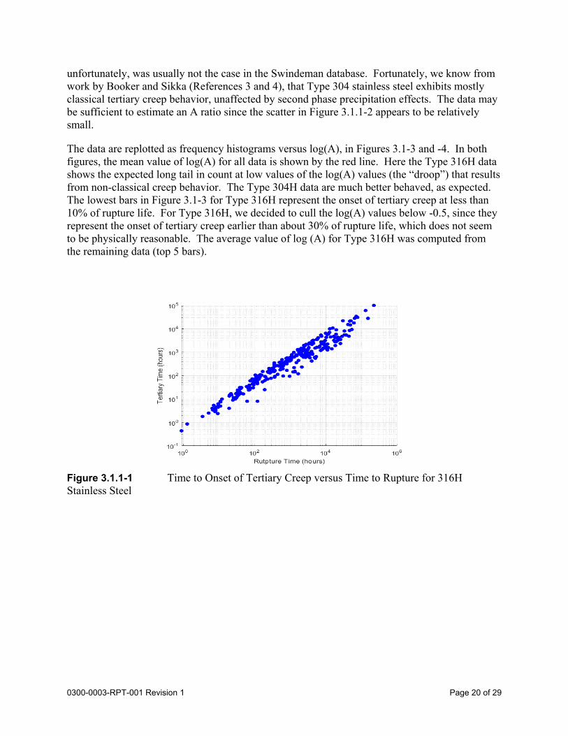
The A ratio is estimated from an evaluation of t3 and tr test results taken from the Swindeman database and shown in Figures 3.1.1-1 and 3.1.1-2, below. Note that the Type 316H stainless steel data in Figure 3.1.1-1 shows considerable scatter and “droop,” which is likely to be due to the effects of non-classical creep and second phase precipitation as described earlier. We note that similar “droop” behavior was observed in Sikka’s 316 data shown in Figure 2.2.1-4.
The 304H data shown in Figure 3.1.1-2 are extremely sparse since they could only be determined when the specimen ID number was recorded, tying tertiary and rupture results together. This,
Page 20 of 290300-0003-RPT-001 Revision 1
unfortunately, was usually not the case in the Swindeman database. Fortunately, we know from work by Booker and Sikka (References 3 and 4), that Type 304 stainless steel exhibits mostly classical tertiary creep behavior, unaffected by second phase precipitation effects. The data may be sufficient to estimate an A ratio since the scatter in Figure 3.1.1-2 appears to be relatively small.
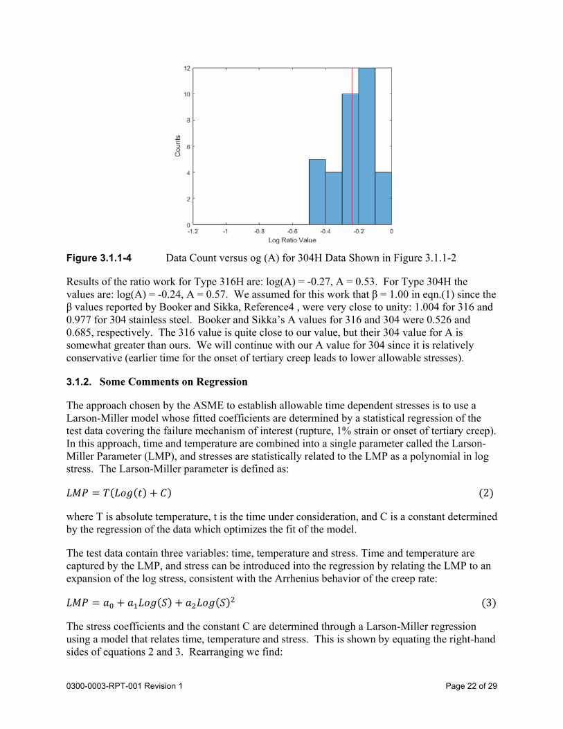
The data are replotted as frequency histograms versus log(A), in Figures 3.1-3 and -4. In both figures, the mean value of log(A) for all data is shown by the red line. Here the Type 316H data shows the expected long tail in count at low values of the log(A) values (the “droop”) that results from non-classical creep behavior. The Type 304H data are much better behaved, as expected. The lowest bars in Figure 3.1-3 for Type 316H represent the onset of tertiary creep at less than 10% of rupture life. For Type 316H, we decided to cull the log(A) values below -0.5, since they represent the onset of tertiary creep earlier than about 30% of rupture life, which does not seem to be physically reasonable. The average value of log (A) for Type 316H was computed from the remaining data (top 5 bars).
Figure 3.1.1-1 Time to Onset of Tertiary Creep versus Time to Rupture for 316H Stainless Steel
Page 21 of 290300-0003-RPT-001 Revision 1
Figure 3.1.1-2 Time to Onset of Tertiary Creep versus Time to Rupture for 304H Stainless Steel
Figure 3.1.1-3 Data Count versus log (A) for 316H Data Shown in Figure 3.1-1
Page 22 of 290300-0003-RPT-001 Revision 1
Figure 3.1.1-4 Data Count versus og (A) for 304H Data Shown in Figure 3.1.1-2
Results of the ratio work for Type 316H are: log(A) = -0.27, A = 0.53. For Type 304H the values are: log(A) = -0.24, A = 0.57. We assumed for this work that β = 1.00 in eqn.(1) since the β values reported by Booker and Sikka, Reference4 , were very close to unity: 1.004 for 316 and 0.977 for 304 stainless steel. Booker and Sikka’s A values for 316 and 304 were 0.526 and 0.685, respectively. The 316 value is quite close to our value, but their 304 value for A is somewhat greater than ours. We will continue with our A value for 304 since it is relatively conservative (earlier time for the onset of tertiary creep leads to lower allowable stresses).
3.1.2. Some Comments on Regression
The approach chosen by the ASME to establish allowable time dependent stresses is to use a Larson-Miller model whose fitted coefficients are determined by a statistical regression of the test data covering the failure mechanism of interest (rupture, 1% strain or onset of tertiary creep). In this approach, time and temperature are combined into a single parameter called the Larson-Miller Parameter (LMP), and stresses are statistically related to the LMP as a polynomial in log stress. The Larson-Miller parameter is defined as:
𝐿𝑀𝑃 𝑇 𝐿𝑜𝑔 𝑡 𝐶 2
where T is absolute temperature, t is the time under consideration, and C is a constant determined by the regression of the data which optimizes the fit of the model.
The test data contain three variables: time, temperature and stress. Time and temperature are captured by the LMP, and stress can be introduced into the regression by relating the LMP to an expansion of the log stress, consistent with the Arrhenius behavior of the creep rate:
𝐿𝑀𝑃 𝑎 𝑎 𝐿𝑜𝑔 𝑆 𝑎 𝐿𝑜𝑔 𝑆 3
The stress coefficients and the constant C are determined through a Larson-Miller regression using a model that relates time, temperature and stress. This is shown by equating the right-hand sides of equations 2 and 3. Rearranging we find:
Page 23 of 290300-0003-RPT-001 Revision 1
log 𝑡𝑎 𝑎 𝐿𝑜𝑔 𝑆 𝑎 𝐿𝑜𝑔 𝑆
𝑇𝐶 4
The regression is performed with log time treated as the dependent variable, in accordance with eqn (4). The standard approach is to use a least squares fit of equation (4) to the time, temperature and stress experimental data. The least squares fit produces stress coefficients, an , and the Larson-Miller C value that minimize the residual error between the measured and calculated log time variable. The a’s and C are the only free parameters, and once these parameters are fitted, there is no further use for the data. The statistical measure of the accuracy of the fit is the square root of the variance or the standard estimate of error, SEE, which has units of log time.
Since we will need the results of the creep rupture regression later, we show the Sengupta and Nestell regression in Figures 3.1.1-5 and -6 for Type 316H and 304H stainless steels, Reference 1. Data were taken from the Swindeman database.
Figure 3.1.1-5 Time-to-Rupture Regression for Type 316H Stainless Steel (Reference 1)
Page 24 of 290300-0003-RPT-001 Revision 1
Figure 3.1.1-6 Time-to-Rupture for Type 304H Stainless Steel (Reference 1)
Both figures demonstrate normal Larson-Miller behavior. The fitted stress coefficients, Larson-Miller constant and SEE for the creep rupture regression for the two alloys are shown in Table 3.1.1-1 below.
304SS 316SS
a0 25496.03 26377.99
a1 -2250.02 -1982.62
a2 -864.43 -866.40
C 15.27 16.282
SEE 0.54 0.35
Table 3-1.1-1 Time to rupture metric (hours, Kelvin, MPa) regression coefficients for 304H and 316H Stainless Steel (Reference 1)
Page 25 of 290300-0003-RPT-001 Revision 1
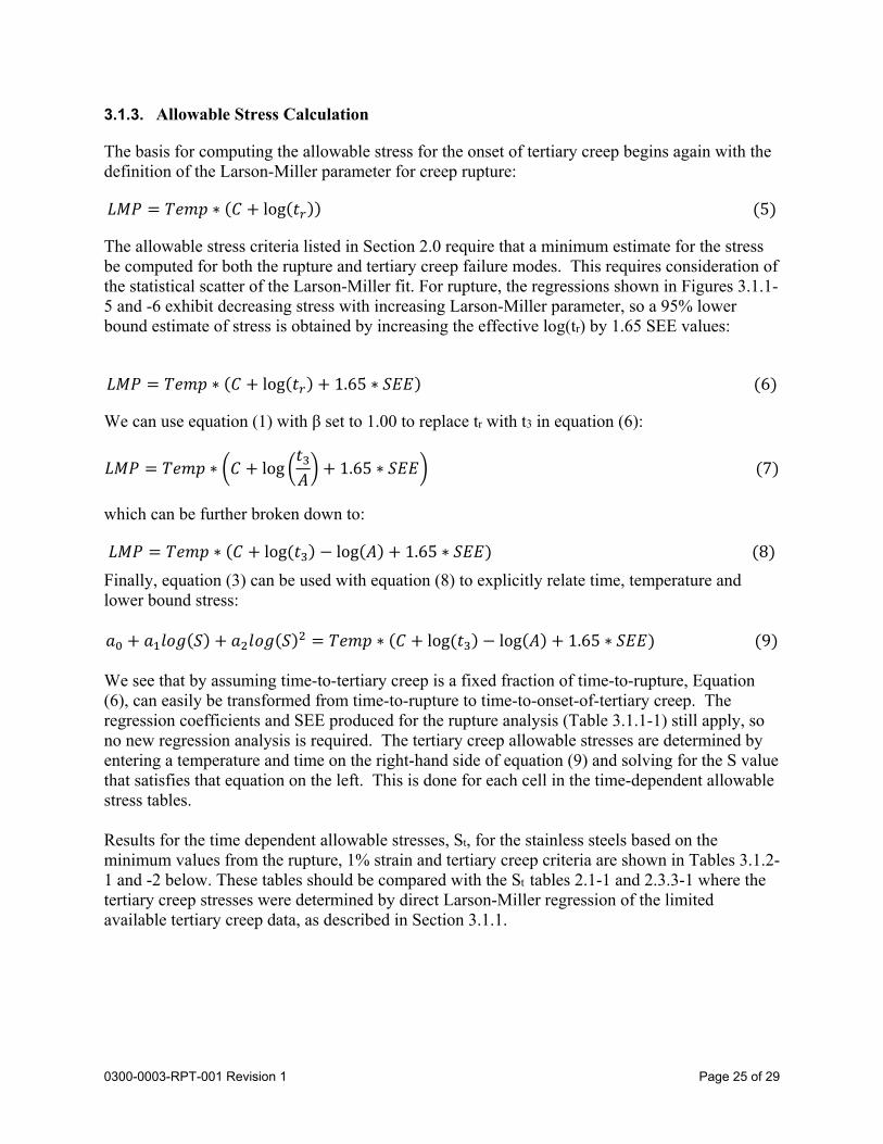
3.1.3. Allowable Stress Calculation
The basis for computing the allowable stress for the onset of tertiary creep begins again with the definition of the Larson-Miller parameter for creep rupture:
𝐿𝑀𝑃 𝑇𝑒𝑚𝑝 ∗ 𝐶 log 𝑡 5
The allowable stress criteria listed in Section 2.0 require that a minimum estimate for the stress be computed for both the rupture and tertiary creep failure modes. This requires consideration of the statistical scatter of the Larson-Miller fit. For rupture, the regressions shown in Figures 3.1.1-5 and -6 exhibit decreasing stress with increasing Larson-Miller parameter, so a 95% lower bound estimate of stress is obtained by increasing the effective log(tr) by 1.65 SEE values:
𝐿𝑀𝑃 𝑇𝑒𝑚𝑝 ∗ 𝐶 log 𝑡 1.65 ∗ 𝑆𝐸𝐸 6
We can use equation (1) with β set to 1.00 to replace tr with t3 in equation (6):
𝐿𝑀𝑃 𝑇𝑒𝑚𝑝 ∗ 𝐶 log𝑡𝐴
1.65 ∗ 𝑆𝐸𝐸 7
which can be further broken down to:
𝐿𝑀𝑃 𝑇𝑒𝑚𝑝 ∗ 𝐶 log 𝑡 log 𝐴 1.65 ∗ 𝑆𝐸𝐸 8
Finally, equation (3) can be used with equation (8) to explicitly relate time, temperature and lower bound stress: 𝑎 𝑎 𝑙𝑜𝑔 𝑆 𝑎 𝑙𝑜𝑔 𝑆 𝑇𝑒𝑚𝑝 ∗ 𝐶 log 𝑡 log 𝐴 1.65 ∗ 𝑆𝐸𝐸 9 We see that by assuming time-to-tertiary creep is a fixed fraction of time-to-rupture, Equation (6), can easily be transformed from time-to-rupture to time-to-onset-of-tertiary creep. The regression coefficients and SEE produced for the rupture analysis (Table 3.1.1-1) still apply, so no new regression analysis is required. The tertiary creep allowable stresses are determined by entering a temperature and time on the right-hand side of equation (9) and solving for the S value that satisfies that equation on the left. This is done for each cell in the time-dependent allowable stress tables. Results for the time dependent allowable stresses, St, for the stainless steels based on the minimum values from the rupture, 1% strain and tertiary creep criteria are shown in Tables 3.1.2-1 and -2 below. These tables should be compared with the St tables 2.1-1 and 2.3.3-1 where the tertiary creep stresses were determined by direct Larson-Miller regression of the limited available tertiary creep data, as described in Section 3.1.1.
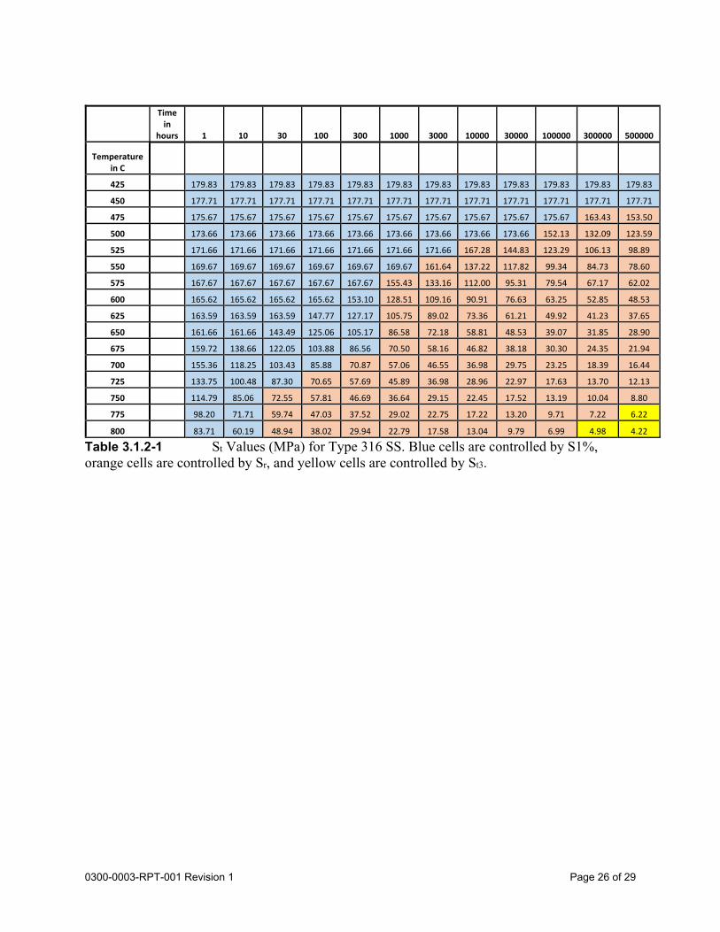
Page 26 of 290300-0003-RPT-001 Revision 1
Table 3.1.2-1 St Values (MPa) for Type 316 SS. Blue cells are controlled by S1%, orange cells are controlled by Sr, and yellow cells are controlled by St3.
Time in
hours 1 10 30 100 300 1000 3000 10000 30000 100000 300000 500000
Temperature in C
425 179.83 179.83 179.83 179.83 179.83 179.83 179.83 179.83 179.83 179.83 179.83 179.83
450 177.71 177.71 177.71 177.71 177.71 177.71 177.71 177.71 177.71 177.71 177.71 177.71
475 175.67 175.67 175.67 175.67 175.67 175.67 175.67 175.67 175.67 175.67 163.43 153.50
500 173.66 173.66 173.66 173.66 173.66 173.66 173.66 173.66 173.66 152.13 132.09 123.59
525 171.66 171.66 171.66 171.66 171.66 171.66 171.66 167.28 144.83 123.29 106.13 98.89
550 169.67 169.67 169.67 169.67 169.67 169.67 161.64 137.22 117.82 99.34 84.73 78.60
575 167.67 167.67 167.67 167.67 167.67 155.43 133.16 112.00 95.31 79.54 67.17 62.02
600 165.62 165.62 165.62 165.62 153.10 128.51 109.16 90.91 76.63 63.25 52.85 48.53
625 163.59 163.59 163.59 147.77 127.17 105.75 89.02 73.36 61.21 49.92 41.23 37.65
650 161.66 161.66 143.49 125.06 105.17 86.58 72.18 58.81 48.53 39.07 31.85 28.90
675 159.72 138.66 122.05 103.88 86.56 70.50 58.16 46.82 38.18 30.30 24.35 21.94
700 155.36 118.25 103.43 85.88 70.87 57.06 46.55 36.98 29.75 23.25 18.39 16.44
725 133.75 100.48 87.30 70.65 57.69 45.89 36.98 28.96 22.97 17.63 13.70 12.13
750 114.79 85.06 72.55 57.81 46.69 36.64 29.15 22.45 17.52 13.19 10.04 8.80
775 98.20 71.71 59.74 47.03 37.52 29.02 22.75 17.22 13.20 9.71 7.22 6.22
800 83.71 60.19 48.94 38.02 29.94 22.79 17.58 13.04 9.79 6.99 4.98 4.22
Page 27 of 290300-0003-RPT-001 Revision 1
Time in
hours 1 10 30 100 300 1000 3000 10000 30000 100000 300000 500000
Temperature in C
425 179.37 179.37 179.37 179.37 179.37 179.37 179.37 179.37 179.37 179.37 169.11 159.92
450 175.88 175.88 175.88 175.88 175.88 175.88 175.88 175.88 175.88 157.56 138.90 130.91
475 172.57 172.57 172.57 172.57 172.57 172.57 172.57 170.52 149.85 129.77 113.54 106.63
500 169.24 169.24 169.24 169.24 169.24 169.24 164.50 141.99 123.88 106.38 92.34 86.39
525 166.00 166.00 166.00 166.00 166.00 158.07 137.53 117.76 101.94 86.77 74.68 69.59
550 162.76 162.76 162.76 162.76 155.30 132.63 114.54 97.23 83.48 70.39 60.04 55.70
575 159.54 159.54 159.54 151.88 130.89 110.86 94.99 79.90 68.01 56.77 47.95 44.27
600 156.32 156.32 152.01 128.51 109.92 92.30 78.42 65.33 55.09 45.49 38.02 34.93
625 153.11 151.32 129.26 108.37 91.96 76.51 64.43 53.12 44.35 36.20 29.92 27.33
650 150.00 129.23 109.55 91.05 76.61 63.12 52.66 42.95 35.47 28.58 23.33 21.18
675 146.70 110.03 92.53 76.20 63.55 51.81 42.79 34.48 28.15 22.38 18.02 16.25
700 134.85 93.37 77.87 63.50 52.46 42.30 34.56 27.50 22.16 17.35 13.76 12.31
725 115.99 78.96 65.27 52.68 43.09 34.33 27.72 21.75 17.29 13.31 10.37 9.21
750 99.49 66.53 54.48 43.50 35.19 27.68 22.07 17.06 13.35 10.08 7.71 6.77
775 85.08 55.84 45.28 35.72 28.57 22.16 17.43 13.24 10.19 7.53 5.63 4.89
800 72.53 46.66 37.44 29.17 23.04 17.61 13.63 10.16 7.67 5.53 4.03 3.45
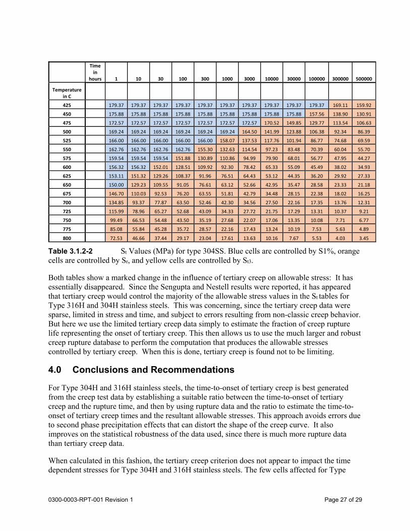
Table 3.1.2-2 St Values (MPa) for type 304SS. Blue cells are controlled by S1%, orange cells are controlled by Sr, and yellow cells are controlled by St3.
Both tables show a marked change in the influence of tertiary creep on allowable stress: It has essentially disappeared. Since the Sengupta and Nestell results were reported, it has appeared that tertiary creep would control the majority of the allowable stress values in the St tables for Type 316H and 304H stainless steels. This was concerning, since the tertiary creep data were sparse, limited in stress and time, and subject to errors resulting from non-classic creep behavior. But here we use the limited tertiary creep data simply to estimate the fraction of creep rupture life representing the onset of tertiary creep. This then allows us to use the much larger and robust creep rupture database to perform the computation that produces the allowable stresses controlled by tertiary creep. When this is done, tertiary creep is found not to be limiting.
4.0 Conclusions and Recommendations
For Type 304H and 316H stainless steels, the time-to-onset of tertiary creep is best generated from the creep test data by establishing a suitable ratio between the time-to-onset of tertiary creep and the rupture time, and then by using rupture data and the ratio to estimate the time-to-onset of tertiary creep times and the resultant allowable stresses. This approach avoids errors due to second phase precipitation effects that can distort the shape of the creep curve. It also improves on the statistical robustness of the data used, since there is much more rupture data than tertiary creep data.
When calculated in this fashion, the tertiary creep criterion does not appear to impact the time dependent stresses for Type 304H and 316H stainless steels. The few cells affected for Type

Page 28 of 290300-0003-RPT-001 Revision 1
316H at the highest temperatures and longest times are cells that will not be populated in the final table due to diffusion creep limits.
We recommend that the ASME proceed with this approach by continuing the work of ASME ST LLC Task 14a using this approach to establish the time-dependent allowable stresses for the stainless steels.
Page 29 of 290300-0003-RPT-001 Revision 1
5.0 References
1. M. Sengupta and J. Nestell. “The Effect of Tertiary Creep on Allowable Stress Values for Type 304 and 316 Stainless Steel for elevated temperature Nuclear Component Design”. ASME 2015 Pressure Vessels & Piping Conference. July 19-23, 2015.
2. W. E. Leyda and J. P. Rowe, “A Study of the Time for Departure from Secondary Creep of Eighteen Steels,” Technical Report P 9-6.1, American Society for Metals, 1969.
3. M. K. Booker and V. K. Sikka (1976), “Interrelationships between Creep Life Criteria for Four Nuclear Structural Materials,” Nuclear Technology, 30:1, 52-64, DOI: 10.13182/NT76-A31623
4. M.K. Booker and V. K. Sikka. “A Study of Tertiary Creep Instability in Several Elevated-Temperature Structural Materials”. Oak Ridge National Laboratory. 1978
5. V. Sikka. “Effects of Thermal Aging on the Mechanical Properties of Type 316 Stainless Steel-Elevated Temperature Properties,” ORNL/TM-8371, Oak Ridge National Laboratory. October, 1982
6. B. Wilshire and H. Burt, "Damage Evolution of Creep of Steels," International Journal of Pressure Vessels and Piping, 85 (2008) 47-54.
7. B. Dyson. “Continuous Cavity Nucleation and Creep Fracture”. Scripta Metallurgica. Vol 17. 1983.
8. V. K. Sikka, B. L. P. Booker, M. K. Booker, and J. W. McEnerney, "Tensile and Creep Data on Type 316 Stainless Steel," ORNL/TM-7110, Oak Ridge National Laboratory, 1980
9. K. Kubo, T. Ohba, K. Kimura, F. Abe and H. Irie (1996), "Effect of Microstructural Evolution on Complex Creep Deformation Behavior of SUS 316 Steel at 823K and 923K," CAMP=ISIJ, 9, 1435
10. K. Kubo, T. Ohba, K. Kimura, F. Abe and K. Yagi (1994), "Effect of Changes in Microstructure on Complex Creep Deformation Behaviour of SUS 316," CAMP-ISIJ, 7, 1791.
11. Email from Douglas Mariott to Robert Swindeman, Subject – RE: Task Squad of the Tertiary Creep Criterion, dated December 3, 2014.
12. Jetter, R. “ Effect of Multiaxial Stress State on Code Allowable Stresses”, CA 1977 13. G Rowe, J. Stewart, and K Burgess. “Capped End, Thin-Wall Tube Creep-Rupture
Behavior for Type 316SS”. Journal of Fluids Engineering. March 1963 14. W. O’Donnell. Letter to Paul Langford. “Tertiary Creep Criterion in Elevated
Temperature Structural Design”. April 28, 2976. 15. R. Swindeman. “A Review of Current Operating Conditions Allowable Stresses in
ASME Section III Subsection NH and Overview of the Availability of the Original and Augmented Databases Needed to Establish S0, St, and Sr”. ASME/DOE Gen-IV Materials Project Task 6. December 14, 2009.