Embed Size (px)
Citation preview
Optical Multiplexer MPM-2000
Installation and Operation Manual
For Products: MPM-2000 Document: 000-10000-120-02-201601

AMERICAS & WORLD HEADQUARTERS
Phone: +1 727-733-2447 Fax: +1 727-733-3962 Sales: [email protected] Orders: [email protected] Support: [email protected]
EUROPE, MIDDLE EAST & AFRICA
Phone: +31 26-319-0500 Fax: +31 26-319-0505 Email: [email protected] Germany : +49 711-341696-0
UK : +44 1865-811118 France : +33 442-386-588
ASIA
Phone: +86 21-6295-6600 Fax: +86 21-6295-6708 Email: [email protected]
Japan & Korea: +82 10-8514-3797
www.oceanoptics.com
Copyright © 2009 Ocean Optics, Inc. All rights reserved. No part of this publication may be reproduced, stored in a retrieval system, or transmitted, by any means, electronic, mechanical, photocopying, recording, or otherwise, without written permission from Ocean Optics, Inc.
Trademarks All products and services herein are the trademarks, service marks, registered trademarks or registered service marks of their respective owners.
Limit of Liability Every effort has been made to make this manual as complete and as accurate as possible, but no warranty or fitness is implied. The information provided is on an “as is” basis. Ocean Optics, Inc. shall have neither liability nor responsibility to any person or entity with respect to any loss or damages arising from the information contained in this manual.
Ocean Optics, Inc. 830 Douglas Ave. Dunedin, FL 34698 USA Manufacturing & Logistics 4301 Metric Dr. Winter Park, FL 32792 USA
Ocean Optics Asia 666 Gubei Road Kirin Tower Suite 601B Changning District Shanghai PRC, 200336
Sales & Support Geograaf 24 6921 EW Duiven The Netherlands Manufacturing & Logistics Maybachstrasse 11 73760 Ostfildern Germany
000-10000-120-02-201601 A
Important Safety Notices
1. Read all safety notices and operating instructions before operating this unit.
2. Inspect the item for transport damage before using the 24VDC power supply for the first time.
3. Adhere to all warning stickers on the unit and all warnings contained in this manual.
Warranty Our 3-Year Warranty covers Ocean Optics miniature fiber-optic spectrometers, spectral sensors, light
sources and sampling accessories – regardless of the application – from manufacturing defects. It also
covers fibers and probes for a full 12 months: http://oceanoptics.com/services/exclusive-3-year-warranty/.
This comprehensive warranty ensures you of the highest level of craftsmanship and reliability for years to
come. No other manufacturer offers such a solid guarantee of quality and reliability.
The Ocean Optics 3-Year Warranty applies to Ocean Optics equipment (excluding OEM configurations)
purchased on or after July 1, 2010. The warranty covers parts and labor needed to repair manufacturing
defects that occur during the warranty period. We also will cover the costs of shipping warranty-related
repairs from our customers to Ocean Optics and from us to our customers.
Warranty Handling
► Procedure
Follow the procedure below to process a warranty claim:
1. Determine the problem or fault with your local distributor.
2. If a problem is evident, obtain an RMA number from your local distributor.
3. Send the equipment to the local distributor for repair. If the item is under warranty, shipping will
be free-of-charge both ways.
4. Contact your distributor for repair and delivery time. If the item is out of warranty, your
distributor will provide a repair cost to you. In this situation, the distributor will not proceed with
the repair until you order it.
Your system will be shipped back to you free of charge with insurance (if under warranty).
ISO Certification Ocean Optics, the industry leader in miniature photonics, has been certified for ISO 9001:2008
certification applicable to the design and manufacture of electro-optical equipment since 2009.

000-10000-120-02-201601 i
Table of Contents
About This Manual ......................................................................................................... iii
Document Purpose and Intended Audience ................................................................... iii
What’s New in this Document ........................................................................................ iii Document Summary .................................................................................................................. iii Product-Related Documentation ............................................................................................... iii
Upgrades ....................................................................................................................... iii
Chapter 1: Setup ................................................................................ 1
Overview ....................................................................................................................... 1
Unpacking the MPM-2000 ............................................................................................. 2
Contents ........................................................................................................................ 2
Typical System Configuration ........................................................................................ 3
Chapter 2: MPM-2000 Specifications ................................................ 5
Operating Environment .................................................................................................. 5
MPM-2000 Components ................................................................................................ 6 Front Panel ................................................................................................................................ 6 Rear Panel ................................................................................................................................. 7
Chapter 3: Operating Instructions .................................................... 9
Operating Software ........................................................................................................ 9 Channel Mode ........................................................................................................................... 10 Program Mode ........................................................................................................................... 11 Small Mode ................................................................................................................................ 12 Main Toolbar .............................................................................................................................. 13 Menu Options ............................................................................................................................ 13 Options Dialog Box .................................................................................................................... 14
MPM-2000.drv ............................................................................................................... 15
Appendix A: RS232 ASCII Commands ............................................. 17
Program File .................................................................................................................. 17 New Data Format ...................................................................................................................... 19
Syntax ........................................................................................................................... 20
Operating/Interfacing with the Optical Multiplexer .......................................................... 21

Table of Contents
ii 000-10000-120-02-201601
Calibrating the MPM-2000 ............................................................................................. 22
Index ................................................................................................... 23
000-10000-120-02-201601 iii
About This Manual
Document Purpose and Intended Audience
This document provides you with an installation section to get your system up and running.
What’s New in this Document
This version of the Optical Multiplexer MPM-2000 Installation and Operation Manual updates the
product photo and manufacturer information..
Document Summary
Chapter Description
Chapter 1: Setup Contains a list of package contents and unpacking instructions.
Chapter 2: MPM-2000 Specifications Contains operating environment specifications, as well as other physical details of the product.
Chapter 3: Operating Instructions Provides instructions for operating Windows-based software that comes with the MPM-2000.
Appendix A: RS232 ASCII Commands Provides the RS232 ASCII command information for the multiplexer.
Product-Related Documentation
You can access documentation for Ocean Optics products by visiting our website at
http://www.oceanoptics.com. Select Support → Technical Documents, then choose the appropriate
document form the available drop-down lists.
Ocean Optics offers a Glossary of spectroscopy terms to help you further understand your state-of-the-art
products and how they function, located at: http://oceanoptics.com/glossary/.
Upgrades Occasionally, you may find that you need Ocean Optics to make a change or an upgrade to your system.
To facilitate these changes, you must first contact Customer Support and obtain a Return Merchandise
Authorization (RMA) number. Please contact an Ocean Optics Application Scientist for specific
instructions when returning a product.

About This Manual
iv 000-10000-120-02-201601
000-10000-120-02-201601 1
Chapter 1
Setup
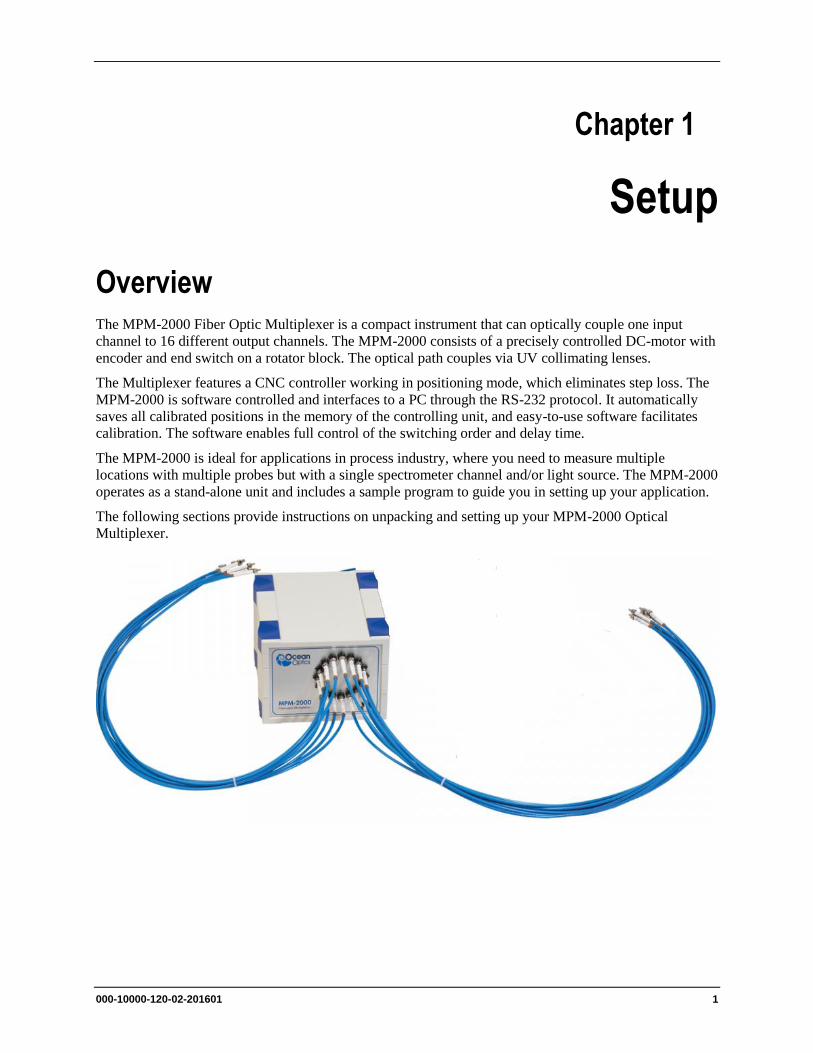
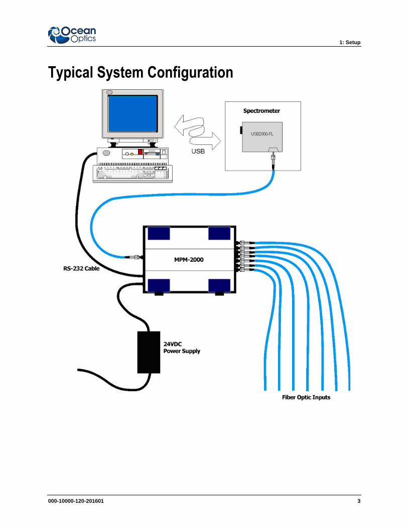
Overview The MPM-2000 Fiber Optic Multiplexer is a compact instrument that can optically couple one input
channel to 16 different output channels. The MPM-2000 consists of a precisely controlled DC-motor with
encoder and end switch on a rotator block. The optical path couples via UV collimating lenses.
The Multiplexer features a CNC controller working in positioning mode, which eliminates step loss. The
MPM-2000 is software controlled and interfaces to a PC through the RS-232 protocol. It automatically
saves all calibrated positions in the memory of the controlling unit, and easy-to-use software facilitates
calibration. The software enables full control of the switching order and delay time.
The MPM-2000 is ideal for applications in process industry, where you need to measure multiple
locations with multiple probes but with a single spectrometer channel and/or light source. The MPM-2000
operates as a stand-alone unit and includes a sample program to guide you in setting up your application.
The following sections provide instructions on unpacking and setting up your MPM-2000 Optical
Multiplexer.
1: Setup
2 000-10000-120-02-201601
Unpacking the MPM-2000 ► Procedure
1. Unpack the Optical Multiplexer carefully. Dropping this instrument can cause permanent
damage.
2. Inspect the outside of the instrument and make sure that there is no damage. Do not use the
instrument if damage is present. Contact your dealer for repair or replacement information, if
necessary.
3. Use this instrument in a clean laboratory environment.
4. Submit the Registration Card to for warranty and support purposes.
Contents Your MPM-2000 Optical Multiplexer package should contain the following:
MPM-2000 Main System
MPM-2000 24VDC Power Supply
Caution
Before using the power supply of the MPM-2000 for the first time, inspect the item for
transport damage. Be sure to adhere to all warnings on the unit and in this operational
manual.
Software CD (contains MPM-2000 software and Calibration software)
PC-MPM-2000 Serial Cable
1: Setup
000-10000-120-201601 3
Typical System Configuration

1: Setup
4 000-10000-120-02-201601
000-10000-120-02-201601 5
Chapter 2
MPM-2000 Specifications
This section provides information on the operating environment and physical controls of the MPM-2000.
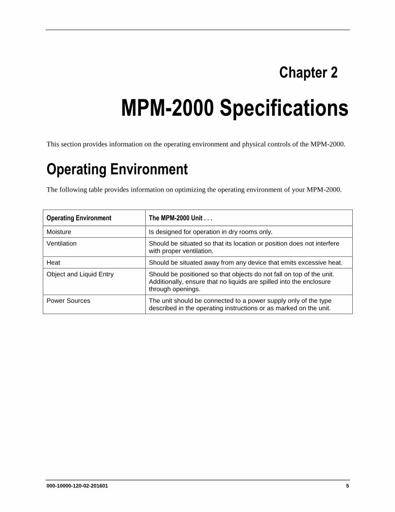
Operating Environment The following table provides information on optimizing the operating environment of your MPM-2000.
Operating Environment The MPM-2000 Unit . . .
Moisture Is designed for operation in dry rooms only.
Ventilation Should be situated so that its location or position does not interfere with proper ventilation.
Heat Should be situated away from any device that emits excessive heat.
Object and Liquid Entry Should be positioned so that objects do not fall on top of the unit. Additionally, ensure that no liquids are spilled into the enclosure through openings.
Power Sources The unit should be connected to a power supply only of the type described in the operating instructions or as marked on the unit.
2: MPM-2000 Specifications
6 000-10000-120-02-201601
MPM-2000 Components The following sections describe the components located on the front and rear of the MPM-2000 unit.
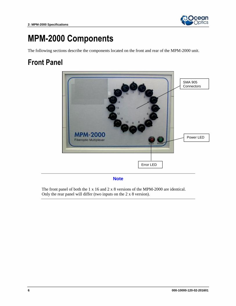
Front Panel
Note
The front panel of both the 1 x 16 and 2 x 8 versions of the MPM-2000 are identical.
Only the rear panel will differ (two inputs on the 2 x 8 version).
Error LED
Power LED
SMA 905 Connectors
2: MPM-2000 Specifications
000-10000-120-201601 7
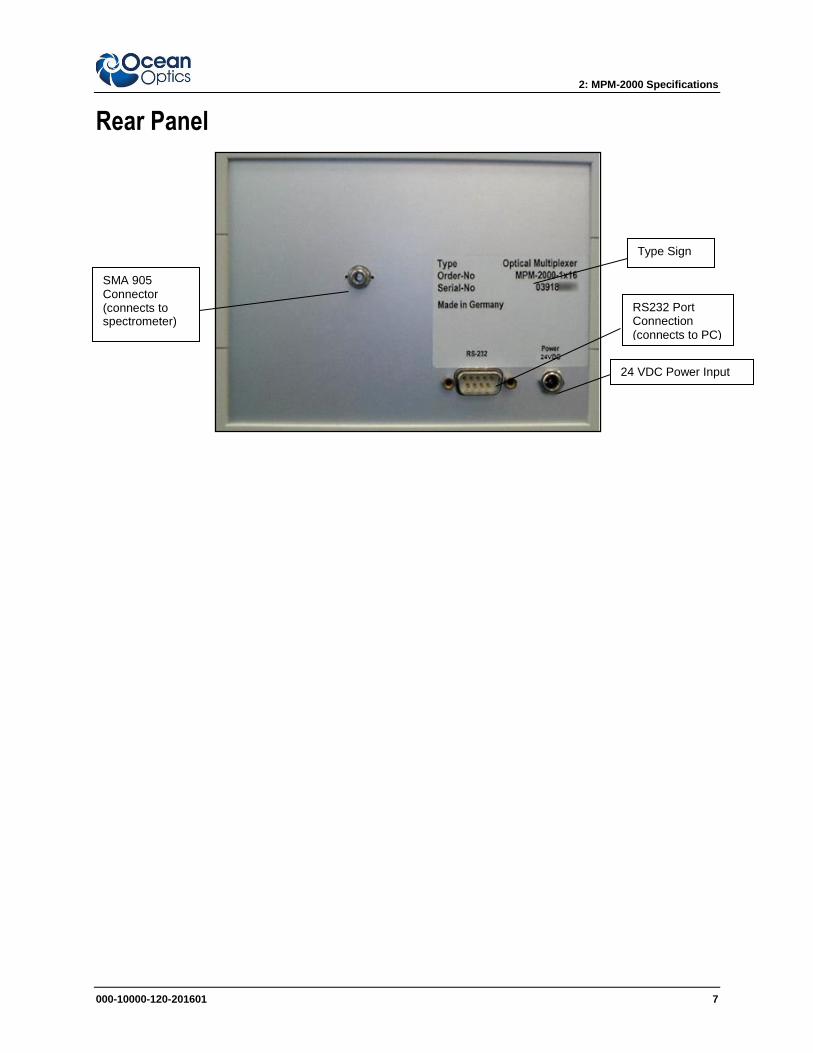
Rear Panel
24 VDC Power Input
RS232 Port Connection (connects to PC)
SMA 905 Connector (connects to spectrometer)
Type Sign

2: MPM-2000 Specifications
8 000-10000-120-02-201601
000-10000-120-02-201601 9
Chapter 3
Operating Instructions
Operating Software The MPM-2000 comes with easy-to-use Windows-based software that allows you to control the MPM-
2000 Optical Multiplexer manually or create sequence programs (scripts) with preconfigured channel
settings and delay times. The graphical software interface allows you to choose from three modes of
operation:
Channel Mode
Program Mode
Small Mode
3: Operating Instructions
10 000-10000-120-02-201601
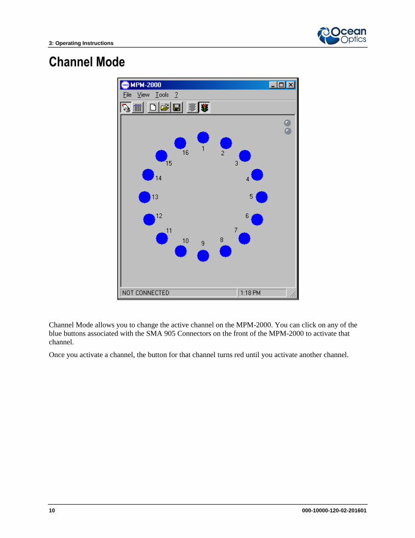
Channel Mode
Channel Mode allows you to change the active channel on the MPM-2000. You can click on any of the
blue buttons associated with the SMA 905 Connectors on the front of the MPM-2000 to activate that
channel.
Once you activate a channel, the button for that channel turns red until you activate another channel.
3: Operating Instructions
000-10000-120-201601 11
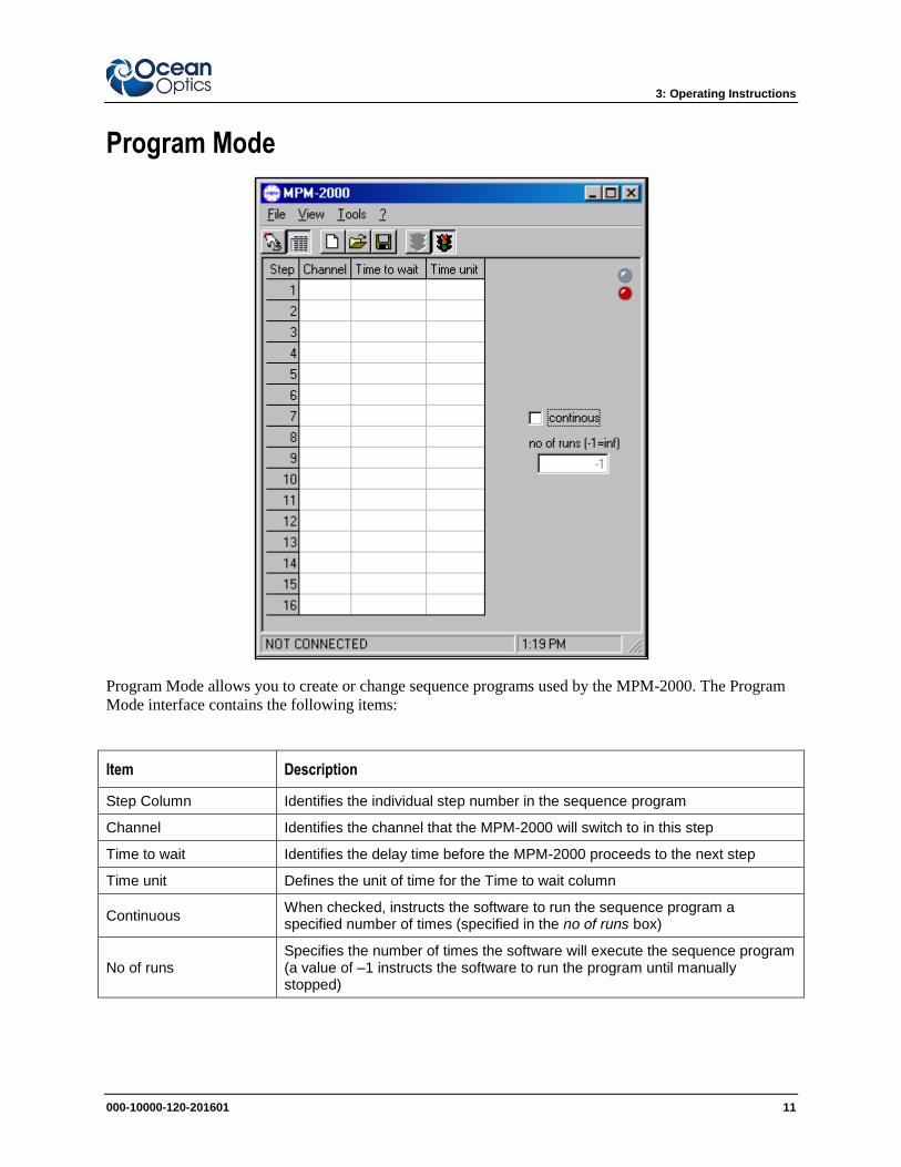
Program Mode
Program Mode allows you to create or change sequence programs used by the MPM-2000. The Program
Mode interface contains the following items:
Item Description
Step Column Identifies the individual step number in the sequence program
Channel Identifies the channel that the MPM-2000 will switch to in this step
Time to wait Identifies the delay time before the MPM-2000 proceeds to the next step
Time unit Defines the unit of time for the Time to wait column
Continuous When checked, instructs the software to run the sequence program a specified number of times (specified in the no of runs box)
No of runs Specifies the number of times the software will execute the sequence program (a value of –1 instructs the software to run the program until manually stopped)
3: Operating Instructions
12 000-10000-120-02-201601
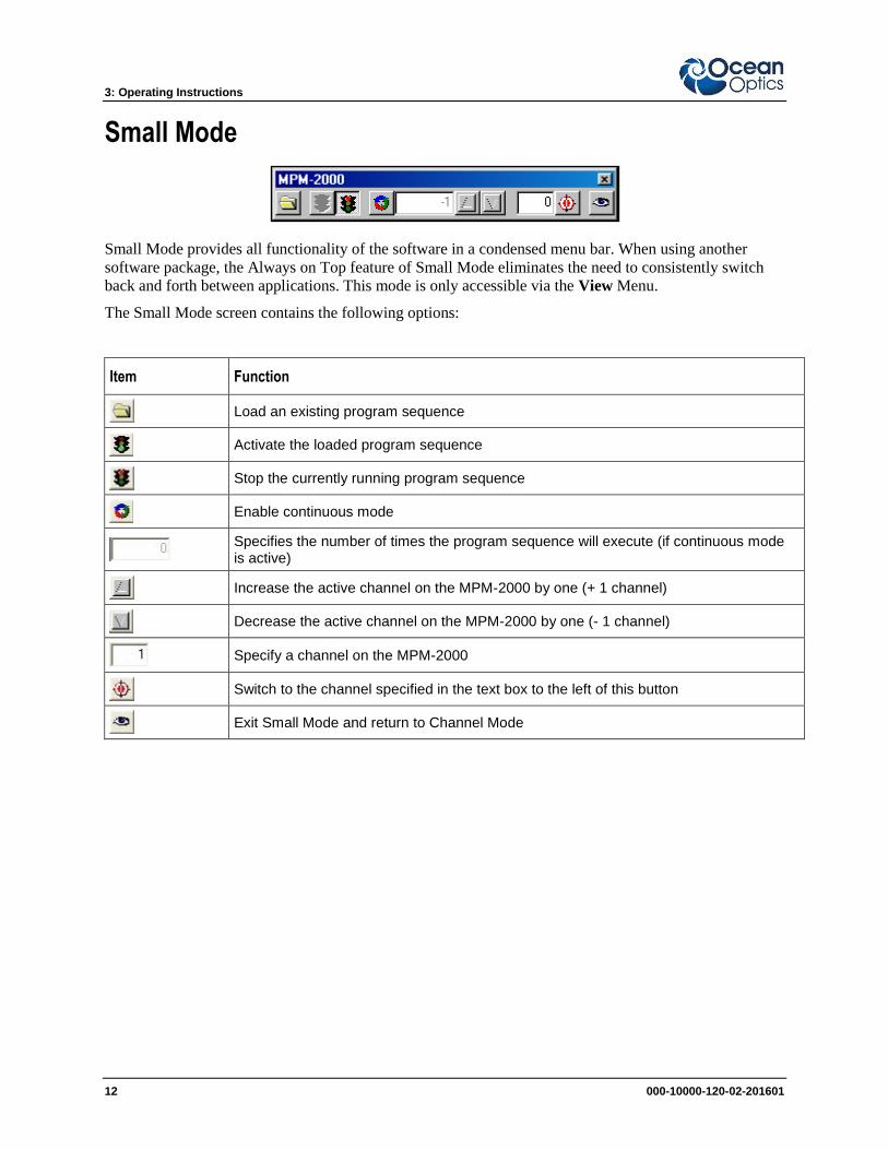
Small Mode
Small Mode provides all functionality of the software in a condensed menu bar. When using another
software package, the Always on Top feature of Small Mode eliminates the need to consistently switch
back and forth between applications. This mode is only accessible via the View Menu.
The Small Mode screen contains the following options:
Item Function
Load an existing program sequence
Activate the loaded program sequence
Stop the currently running program sequence
Enable continuous mode
Specifies the number of times the program sequence will execute (if continuous mode is active)
Increase the active channel on the MPM-2000 by one (+ 1 channel)
Decrease the active channel on the MPM-2000 by one (- 1 channel)
Specify a channel on the MPM-2000
Switch to the channel specified in the text box to the left of this button
Exit Small Mode and return to Channel Mode
3: Operating Instructions
000-10000-120-201601 13
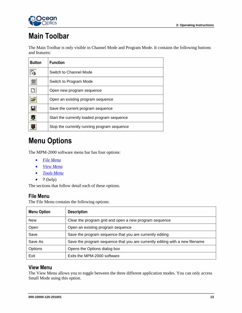
Main Toolbar
The Main Toolbar is only visible in Channel Mode and Program Mode. It contains the following buttons
and features:
Button Function
Switch to Channel Mode
Switch to Program Mode
Open new program sequence
Open an existing program sequence
Save the current program sequence
Start the currently loaded program sequence
Stop the currently running program sequence
Menu Options
The MPM-2000 software menu bar has four options:
File Menu
View Menu
Tools Menu
? (help)
The sections that follow detail each of these options.
File Menu The File Menu contains the following options:
Menu Option Description
New Clear the program grid and open a new program sequence
Open Open an existing program sequence
Save Save the program sequence that you are currently editing
Save As Save the program sequence that you are currently editing with a new filename
Options Opens the Options dialog box
Exit Exits the MPM-2000 software
View Menu The View Menu allows you to toggle between the three different application modes. You can only access
Small Mode using this option.
3: Operating Instructions
14 000-10000-120-02-201601
Tools Menu The Tools Menu contains the following options:
Menu Option Description
Connect Connects to the MPM-2000
Disconnect Disconnects from the MPM-2000
Options Opens the Options dialog box
Options Dialog Box
The Options dialog box is accessible from the File Menu or Tools Menu. It contains the following two
tabs:
Comport Tab
Settings Tab
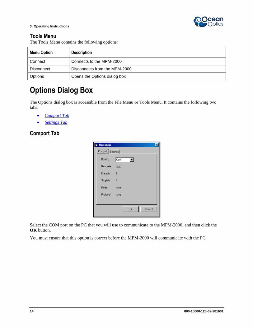
Comport Tab
Select the COM port on the PC that you will use to communicate to the MPM-2000, and then click the
OK button.
You must ensure that this option is correct before the MPM-2000 will communicate with the PC.
3: Operating Instructions
000-10000-120-201601 15
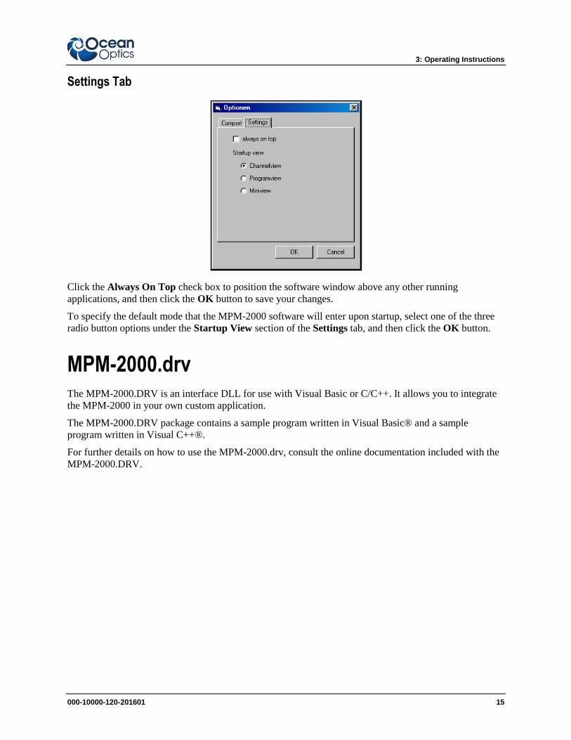
Settings Tab
Click the Always On Top check box to position the software window above any other running
applications, and then click the OK button to save your changes.
To specify the default mode that the MPM-2000 software will enter upon startup, select one of the three
radio button options under the Startup View section of the Settings tab, and then click the OK button.
MPM-2000.drv The MPM-2000.DRV is an interface DLL for use with Visual Basic or C/C++. It allows you to integrate
the MPM-2000 in your own custom application.
The MPM-2000.DRV package contains a sample program written in Visual Basic® and a sample
program written in Visual C++®.
For further details on how to use the MPM-2000.drv, consult the online documentation included with the
MPM-2000.DRV.

3: Operating Instructions
16 000-10000-120-02-201601
000-10000-120-02-201601 17
Appendix A
RS232 ASCII Commands
Program File The MPM-2000 Optical Multiplexer is interfaced via the RS232 protocol.
The settings for the serial communications are:
Baudrate: 9600
Databits: 8
Parity: None
Stop bits: 1
Handshaking: None
A program file stored in the MPM-2000’s EEPROM contains all necessary data:
Serial Number
Software Version Number (only for the windows software)
Calibration data (positions of all 16 channels)
Startup / Reference-sequence
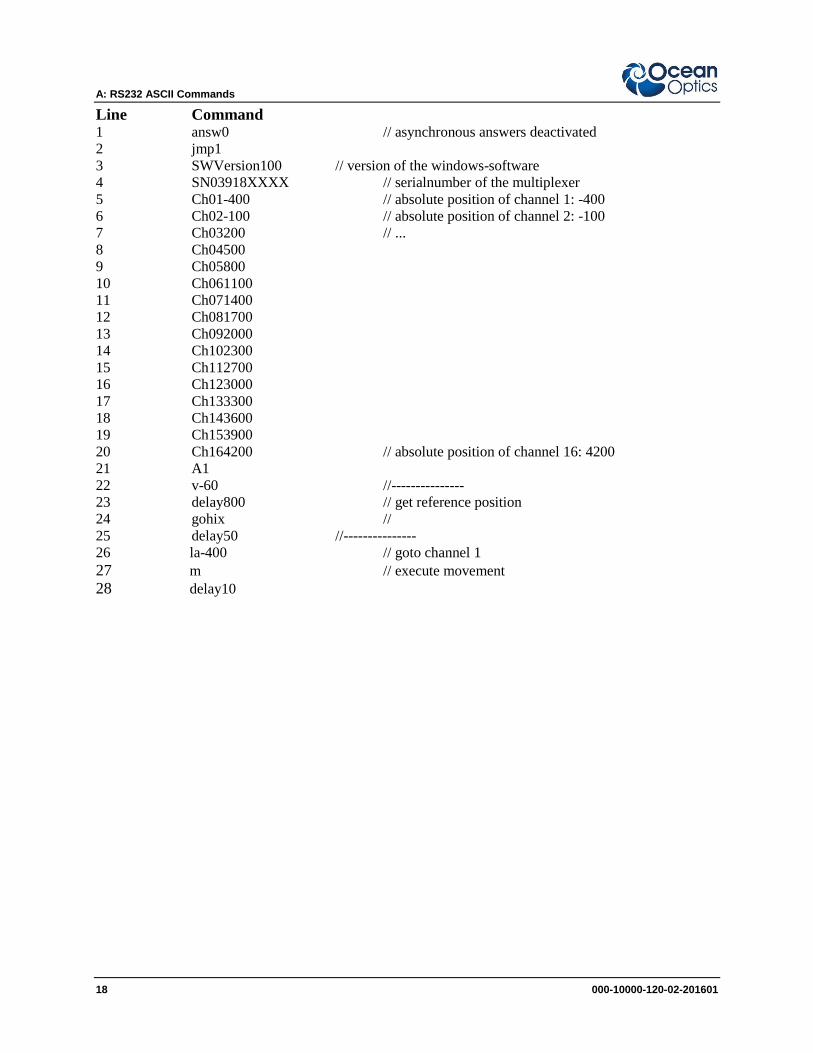
The program file looks like the following sample code except for the position data.
Note
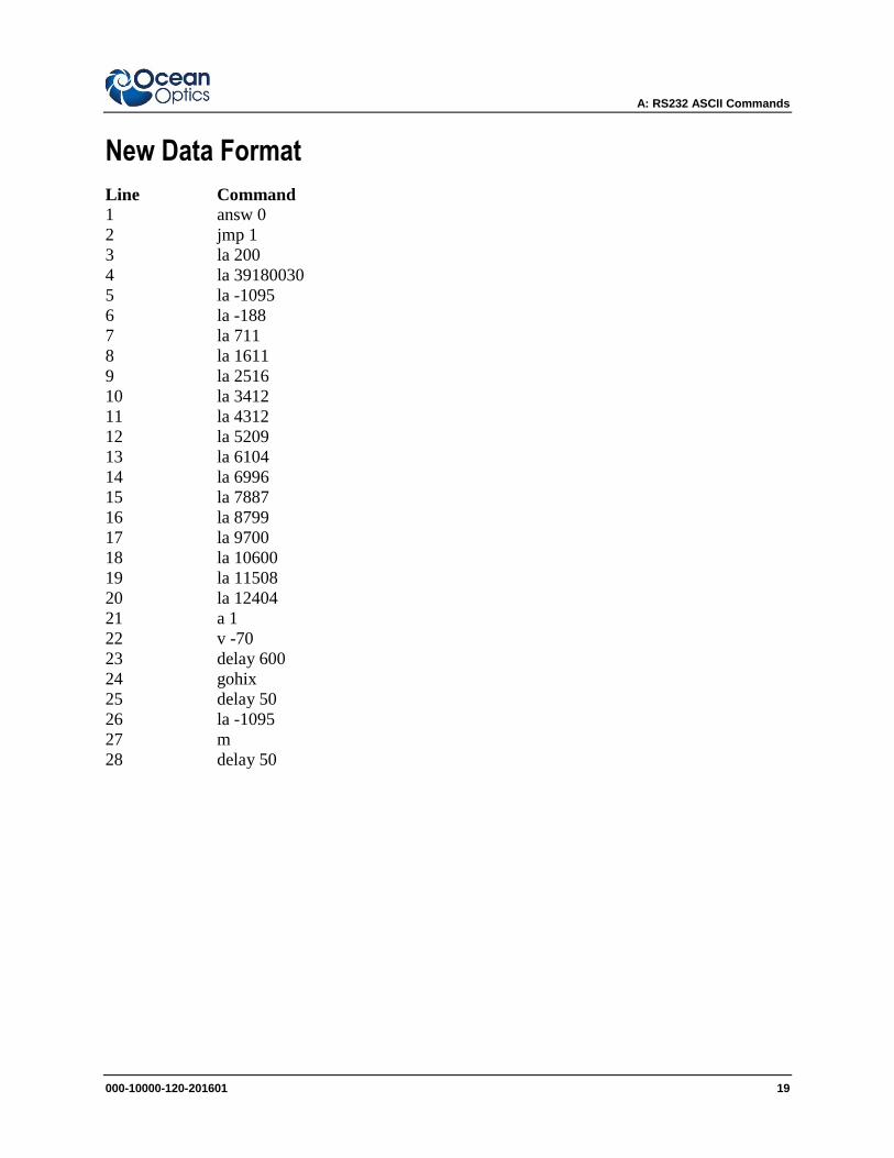
For new devices with serial numbers of 039180029 and above or 050460021 and above,
see New Data Format.
A: RS232 ASCII Commands
18 000-10000-120-02-201601
Line Command 1 answ0 // asynchronous answers deactivated
2 jmp1
3 SWVersion100 // version of the windows-software
4 SN03918XXXX // serialnumber of the multiplexer
5 Ch01-400 // absolute position of channel 1: -400
6 Ch02-100 // absolute position of channel 2: -100
7 Ch03200 // ...
8 Ch04500
9 Ch05800
10 Ch061100
11 Ch071400
12 Ch081700
13 Ch092000
14 Ch102300
15 Ch112700
16 Ch123000
17 Ch133300
18 Ch143600
19 Ch153900
20 Ch164200 // absolute position of channel 16: 4200
21 A1
22 v-60 //---------------
23 delay800 // get reference position
24 gohix //
25 delay50 //---------------
26 la-400 // goto channel 1
27 m // execute movement 28 delay10
A: RS232 ASCII Commands
000-10000-120-201601 19
New Data Format
Line Command
1 answ 0
2 jmp 1
3 la 200
4 la 39180030
5 la -1095
6 la -188
7 la 711
8 la 1611
9 la 2516
10 la 3412
11 la 4312
12 la 5209
13 la 6104
14 la 6996
15 la 7887
16 la 8799
17 la 9700
18 la 10600
19 la 11508
20 la 12404
21 a 1
22 v -70
23 delay 600
24 gohix
25 delay 50
26 la -1095
27 m
28 delay 50
A: RS232 ASCII Commands
20 000-10000-120-02-201601
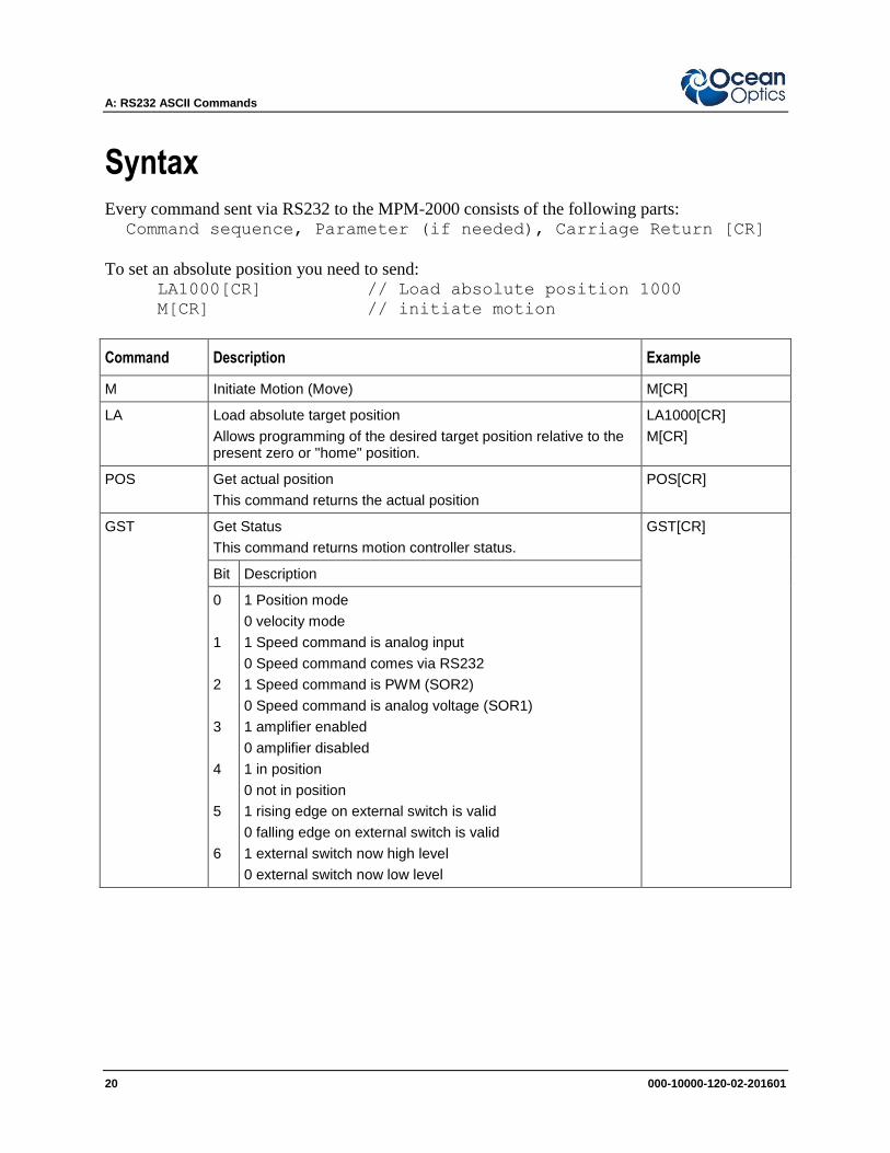
Syntax Every command sent via RS232 to the MPM-2000 consists of the following parts: Command sequence, Parameter (if needed), Carriage Return [CR]
To set an absolute position you need to send: LA1000[CR] // Load absolute position 1000
M[CR] // initiate motion
Command Description Example
M Initiate Motion (Move) M[CR]
LA Load absolute target position
Allows programming of the desired target position relative to the present zero or "home" position.
LA1000[CR]
M[CR]
POS Get actual position
This command returns the actual position
POS[CR]
GST Get Status
This command returns motion controller status.
GST[CR]
Bit Description
0
1
2
3
4
5
6
1 Position mode
0 velocity mode
1 Speed command is analog input
0 Speed command comes via RS232
1 Speed command is PWM (SOR2)
0 Speed command is analog voltage (SOR1)
1 amplifier enabled
0 amplifier disabled
1 in position
0 not in position
1 rising edge on external switch is valid
0 falling edge on external switch is valid
1 external switch now high level
0 external switch now low level
A: RS232 ASCII Commands
000-10000-120-201601 21
Command Description Example
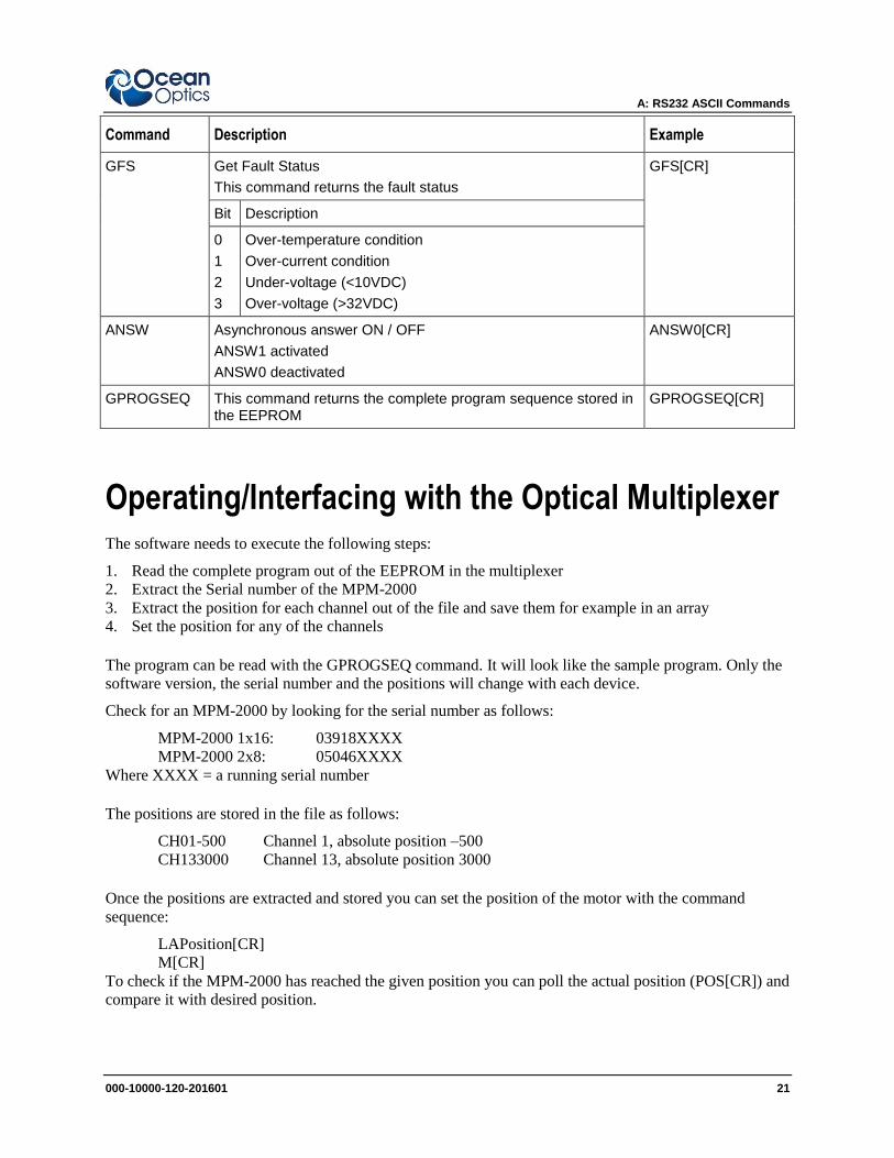
GFS Get Fault Status
This command returns the fault status
GFS[CR]
Bit Description
0
1
2
3
Over-temperature condition
Over-current condition
Under-voltage (<10VDC)
Over-voltage (>32VDC)
ANSW Asynchronous answer ON / OFF
ANSW1 activated
ANSW0 deactivated
ANSW0[CR]
GPROGSEQ This command returns the complete program sequence stored in the EEPROM
GPROGSEQ[CR]
Operating/Interfacing with the Optical Multiplexer The software needs to execute the following steps:
1. Read the complete program out of the EEPROM in the multiplexer
2. Extract the Serial number of the MPM-2000
3. Extract the position for each channel out of the file and save them for example in an array
4. Set the position for any of the channels
The program can be read with the GPROGSEQ command. It will look like the sample program. Only the
software version, the serial number and the positions will change with each device.
Check for an MPM-2000 by looking for the serial number as follows:
MPM-2000 1x16: 03918XXXX
MPM-2000 2x8: 05046XXXX
Where XXXX = a running serial number
The positions are stored in the file as follows:
CH01-500 Channel 1, absolute position –500
CH133000 Channel 13, absolute position 3000
Once the positions are extracted and stored you can set the position of the motor with the command
sequence:
LAPosition[CR]
M[CR]
To check if the MPM-2000 has reached the given position you can poll the actual position (POS[CR]) and
compare it with desired position.
A: RS232 ASCII Commands
22 000-10000-120-02-201601
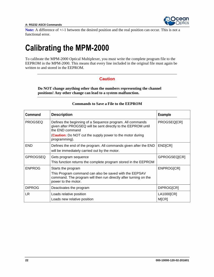
Note: A difference of +/-1 between the desired position and the real position can occur. This is not a
functional error.
Calibrating the MPM-2000 To calibrate the MPM-2000 Optical Multiplexer, you must write the complete program file to the
EEPROM in the MPM-2000. This means that every line included in the original file must again be
written to and stored in the EEPROM.
Caution
Do NOT change anything other than the numbers representing the channel
positions! Any other change can lead to a system malfunction.
Commands to Save a File to the EEPROM
Command Description Example
PROGSEQ Defines the beginning of a Sequence program. All commands given after PROGSEQ will be sent directly to the EEPROM until the END command
(Caution: Do NOT cut the supply power to the motor during programming).
PROGSEQ[CR]
END Defines the end of the program. All commands given after the END
will be immediately carried out by the motor.
END[CR]
GPROGSEQ Gets program sequence
This function returns the complete program stored in the EEPROM
GPROGSEQ[CR]
ENPROG Starts the program
This Program command can also be saved with the EEPSAV command. The program will then run directly after turning on the power to the motor.
ENPROG[CR]
DIPROG Deactivates the program DIPROG[CR]
LR Loads relative position
Loads new relative position
LA1000[CR]
M[CR]
000-10000-120-02-201601 23
Index
A ASCII commands, 17
C calibrating, 22
Channel Mode, 10
components, 6
front panel, 6
rear panel, 7
Comport Tab, 14
configuration
typical system, 3
D document
audience, iii
purpose, iii
summary, iii
F File Menu, 13
I interfacing
with multiplexer, 21
ISO certification, A
M Main Toolbar, 13
menu
File, 13
Tools, 14
View, 13
Menu Options, 13
mode
Channel, 10
Program, 11
Small, 12
MPM-2000.drv, 15
O operating environment, 5
operating instructions, 9
Options Dialog Box, 14
P package contents, 2
product-related documentation, iii
program file, 17
syntax, 20
Program Mode, 11
R RS232, 17
S Settings Tab, 15
setup, 1
Small Mode, 12
software, 9
specifications, 5
T tab
Comport, 14
Settings, 15
Tools Menu, 14
U unpacking procedure, 2
upgrades, iii
Index
24 000-10000-120-02-201601
V View Menu, 13
W warranty, A
what's new, iii