Embed Size (px)
DESCRIPTION
Technical
Citation preview

1
Slides from “MPLS Architectural Considerations for a Transport Profile” RFC 5317 JWT Report
and from references
Other references:
RFC 5654 Requirements of an MPLS Transport Profile
Draft-ietf-mpls-tp-oam-analysis-02
Draft-ietf-mpls-tp-oam-framework-09
Draft-ietf-mpls-tp-oam-fault-02
Cisco whitepaper “Understanding MPLS-TP and it’s benefits”

2
Table of Contents
• Executive Overview– Recommendation
• Introduction and Background Material• High Level Architecture• OAM Requirements• OAM Mechanisms and Baseline Use Cases• Associated Channel Level (ACH)• Forwarding and OAM
– LSP/PW OAM– Use Case Scenario and Label Stack Diagrams– Use of TTL for MIP OAM alert
• Control Plane• Survivability• Network Management• Summary

3
Executive Summary

4
Recommendation Consensus on recommendation of Option 1
– Jointly agree to work together and bring transport requirements into the IETF and extend IETF MPLS forwarding, OAM, survivability, network management and control plane protocols to meet those requirements through the IETF Standards Process
– The Joint Working Team believes this would fulfill the mutual goal of improving the functionality of the transport networks and the internet and guaranteeing complete interoperability and architectural soundness
– Refer to the technology as the Transport Profile for MPLS (MPLS-TP)
– Therefore, we recommend that future work should focus on:
• In the IETF: Definition of the MPLS “Transport Profile” (MPLS-TP)
• In the ITU-T:
– Integration of MPLS-TP into the transport network
– Alignment of the current T-MPLS Recommendations with MPLS-TP and,
– Terminate the work on current T-MPLS
The technical feasibility analysis demonstrated there were no “show stopper” issues in the recommendation of Option 1 and that the IETF MPLS and Pseudowire architecture could be extended to support transport functional requirements
– Therefore the team believed that there was no need for the analysis of any other option

5
Development of ITU-T Recommendations on MPLS-TP
The normative definition of the MPLS-TP that supports the ITU-T transport network requirements will be captured in IETF RFCs
The ITU-T will:– Develop Recommendations to allow MPLS-TP to be integrated with current
transport equipment and networks
• Including in agreement with the IETF, the definition of any ITU-T specific functionality within the MPLS-TP architecture
– Via the MPLS change process (RFC 4929)
• Revise existing Recommendations to align with MPLS-TP
– It is anticipated that following areas will be in scope. The actual Recommendations will be identified by the questions responsible for the topic areas.
• Architecture (e.g. G.8110.1)
• Equipment (e.g. G.8121)
• Protection (e.g. G.8131, G.8132)
• OAM (e.g. G.8113, G.8114)
• Network management (e.g. G.7710, G.7712, G.8151, …)
• Control plane (e.g. G.7713, G.7715, …)
– ITU-T Recommendations will make normative references to the appropriate RFCs

6
Introduction andBackground Material

7
What am I reading?
This presentation is a collection of assumptions, discussion points and decisions that the combined group has had during the months of March and April, 2008
This represents the agreed upon starting point for the technical analysis of the T-MPLS requirements from the ITU-T and the MPLS architecture to meet those requirements
The output of this technical analysis is the recommendation given to SG 15 on how to reply to the IETF’s liaison of July 2007
– IETF requested decision on whether the SDOs work together and extend MPLS aka “option 1: or
– ITU-T choose another ethertype and rename T-MPLS to not include the MPLS moniker aka “option 2”
The starting point of the analysis is to attempt to satisfy option 1 by showing the high level architecture, any showstoppers and the design points that would need to be addressed after the decision has been made to work together.
Option 1 was stated as preferred by the IETF and if it can be met; Option 2 will not be explored
8
Some contributors to this architecture
BT Verizon ATT NTT Comcast Acreo AB Alcatel-Lucent Cisco Ericsson Huawei Juniper Nortel Old Dog Consulting

9
How is the effort organized?
1. In ITU-T
TMPLS ad hoc group
2. In IETF
MPLS interoperability design team
3. DMZ between the SDOs: Joint Working Team
Segmented into groups looking at
1. Forwarding
2. OAM
3. Protection
4. Control Plane
5. Network Management
Goal: Produce a technical analysis showing that MPLS architecture can perform functionality required by a transport profile.
Compare w/ ITU-T requirements and identify showstoppers
Find any obvious design points in MPLS architecture that may need extensions
10
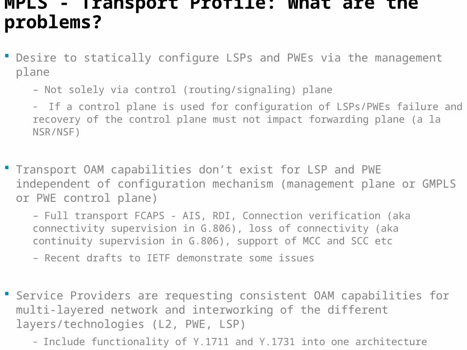
MPLS - Transport Profile: What are the problems?
Desire to statically configure LSPs and PWEs via the management plane
– Not solely via control (routing/signaling) plane
– If a control plane is used for configuration of LSPs/PWEs failure and recovery of the control plane must not impact forwarding plane (a la NSR/NSF)
Transport OAM capabilities don’t exist for LSP and PWE independent of configuration mechanism (management plane or GMPLS or PWE control plane)
– Full transport FCAPS - AIS, RDI, Connection verification (aka connectivity supervision in G.806), loss of connectivity (aka continuity supervision in G.806), support of MCC and SCC etc
– Recent drafts to IETF demonstrate some issues
Service Providers are requesting consistent OAM capabilities for multi-layered network and interworking of the different layers/technologies (L2, PWE, LSP)
– Include functionality of Y.1711 and Y.1731 into one architecture
11
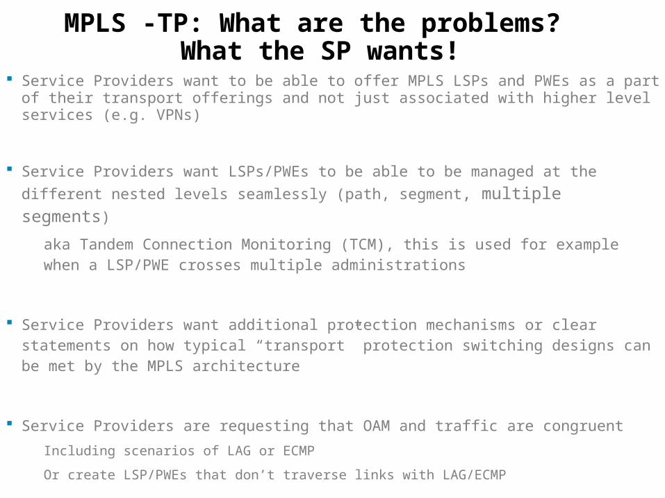
MPLS -TP: What are the problems? What the SP wants!
Service Providers want to be able to offer MPLS LSPs and PWEs as a part of their transport offerings and not just associated with higher level services (e.g. VPNs)
Service Providers want LSPs/PWEs to be able to be managed at the different nested
levels seamlessly (path, segment, multiple segments)
aka Tandem Connection Monitoring (TCM), this is used for example when a LSP/PWE crosses multiple administrations
Service Providers want additional protection mechanisms or clear statements on how typical “transport” protection switching designs can be met by the MPLS architecture
Service Providers are requesting that OAM and traffic are congruent
Including scenarios of LAG or ECMP
Or create LSP/PWEs that don’t traverse links with LAG/ECMP

12
MPLS - TP Requirements Overview
Meet functional requirements stated earlier by service providers
No modification to MPLS forwarding architecture
Solution Based on existing Pseudo-wire and LSP constructs
Bi-directional congruent p2p LSPs
No LSP merging (e.g. no use of LDP mp2p signaling in order to avoid losing
LSP head-end information)
Multicast is point to multipoint not MP2MP

13
MPLS - TP Requirements Overview .2
OAM function responsible for monitoring the LSP/PWE
Initiates path recovery actions
IP forwarding is not required to support of OAM or data packets
OOB management network running IP is outside scope of feasibility study
Can be used with static provisioning systems or with control plane
With static provisioning, no dependency on routing or signaling (e.g. GMPLS or, IGP, RSVP, BGP, LDP)
Mechanisms and capabilities must be able to interoperate with existing MPLS and PWE control and forwarding planes
14
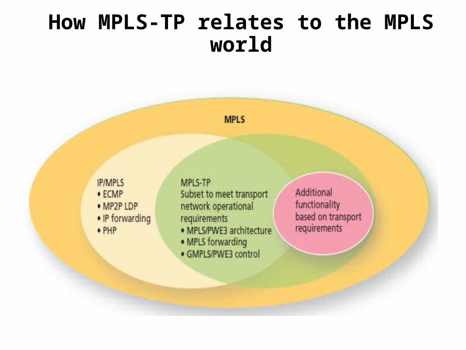
How MPLS-TP relates to the MPLS world

15
MPLS-TP Major Solution Constructs NOTE: These two constructs were used as the basis for the Technical Feasibility study performed
by the ad hoc team, JWT and IETF MPLS Interoperability Design Team
1. Definition of MPLS-TP alert label (TAL) and a Generic Associated Channel (GE ACH)
Allows OAM packets to be directed to an intermediated node on a LSP/PWE
Via label stacking or proper TTL setting
Define a new reserved label (13 is suggested):
It is believed that Label 14 cannot be reused at this point
2. Generic Associated Channel (GE ACH) functionality supports the FCAPS functions by carrying OAM, APS, ECC etc. packets across the network
Use of PWE-3 Associated Channel to carry OAM packets
GE ACH are codepoints from PWE ACH space but, not necessarily, for PWE purposes
GE ACH would be present for OAM of all LSPs

16
Generic Associated Channel
1.The OAM msgs are transported through the same data paths to support FCAPS
• Fault, Configuration, Accounting, Performance and Security functions
• It implies that OAM monitors PW and LSPs
2.The G-ACH is used in both PWs and LSPs, while the GAL is used to flag the G-ACH in MPLS-TP LSPs.

17
Associated Channel Level ACH: Overview
Generalised mechanism for carrying management / OAM information OAM capabilities : Connectivity Checks (CC) and “Connectivity Verification” (CV)Management information: Embedded Control Channel (ECC)
To support the Data Communications Network (DCN) and the Signalling Communication Network (SCN) – see G.7712
APS information Associated Channel Capabilities
Multiple channels can exist between end pointsChannel Type Indicates what protocol that is carriedTo service an MPLS-TP network new channel types will need to be defined
Management and Control Plane Information (DCN and SCN connectivity)Via ECC where IP is not configured
Generic ACH contains a “channel Type” fieldNeed for a registry of protocolsThis needs to be blocked for different functions(IP-Free BFD is currently 7)
We may want to define a vendor specific and experimental range
No Showstoppers found

18
MPLS-TP Major Solution Observations
1. Bringing ACH functionality into LSPs begins to blur the architectural line between an MPLS LSP and an MPLS Pseudowire
The functional differences between an MPLS LSP and MPLS PW must be retained in the architecture
2. The same OAM mechanism (e.g. ACH) can be unified for LSPs and PWE
Enabling the same functionality for both and ease of implementation
Avoid breaking anything (e.g. ECMP)
There may be specific differences that are discovered in design phase
ACH functionality for LSPs should be limited to only OAM, APS & ECC management channel data
3. A great deal of IETF protocol, design and architectural reuse can be employed to solve the requirements
No fundamental change to the IETF MPLS architecture was found to be necessary

19
Main differences from MPLS

20
MPLS-TP can be regarded as a subset of MPLS. The TP encompasses the maintenance operation (service and operation) of existing transport networks.
1- MPLS does not satisfy the requirements of maintenance operation level in the transport network, despite the fault detection tools (Virtual Circuit Connectivity Verification, Bidirectional Forwarding Detection and LSP-Ping)
2- PHP, LAG and ECMP are turned-off as they introduce the lack the tracebility which makes difficult the management of a connection-oriented path.
3- In MPLS the paths are controlled by the control plane in a soft state which implies that a fault in the control plane will have negative impact on user traffic even if there is no problem in the transport plane. In MPLS-TP the management plane is responsible for the path management and operators can manually manage the paths.

21
MPLS-TP is :
1- Strictly connection-oriented
2- Client-agnostic (Can carry L1, L2, L3 services)
3- Physical layer agnostic
4- Provides strong OAM functions as those provided in
transport/carrier networks. These OAM functions are integral
part of the MPLS-TP data plane and independent of the control
plane.
MPLS-TP Main Characteristics (1)

22
5- It provides several protection schemes at the data plane
similar to those available in traditional optical transport network.
6- Allows network provisioning via a centralized NMS and/or a
distributed control plane.
7- The GMPLS control plane is also applicable to the MPLS-TP
client or server layers allowing a common approach for
management and control of multi-layer transport networks.
8- The control plane does not make NMS obsolete. The NMS
needs to configure the control plane and interact with it for
connection management.
MPLS-TP Main Characteristics (2)

23
High Level Architecture

24
MPLS+TP Static Provisioning
Forwarding Tables
Forwarding Tables
Forwarding Tables
Edge Edge
Network Management SystemControl Plane for PT2PT services
Static provisioning and dynamic control planeRequirements state that the solution must include static only provisioning
Any dynamic Control plane will be based on IETF solutions (GMPLS, IP/MPLS)
Control Plane responsible for:End to End, Segment LSPs and PWE-3 application labels (programming the LFIB)
Determining and defining primary and backup paths
Configuring the OAM function along the path
Others : Defining the UNI etc
OAM responsible for monitoring and driving switches between primary and backup paths for the end to end path and path segments
OAM OAM OAM

25
MPLS Transport Profile - Terminology
Definition of an MPLS Transport Profile (TP) within IETF MPLS standardsBased on PWE3 and LSP forwarding architecture IETF MPLS architecture concepts
The major construct of the transport profile for MPLS are LSPsPW are a client layer
Multi-node PSN cloud
Pseudo-wire
PW1
Emulated Service
AttachmentCircuit
PE1 PE2CE1 CE2
AttachmentCircuit
26
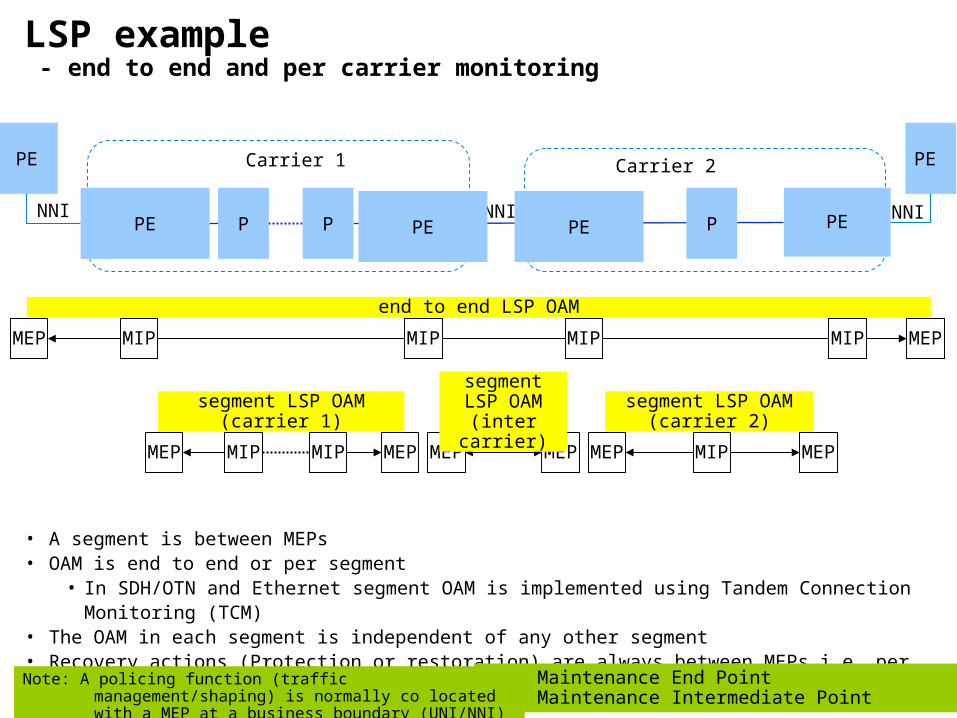
LSP example - end to end and per carrier monitoring
P P
MEP MIP MIP MEP
MEP MEPMEP MEP MEP MEP MIPMIP
• A segment is between MEPs• OAM is end to end or per segment
• In SDH/OTN and Ethernet segment OAM is implemented using Tandem Connection Monitoring (TCM)
• The OAM in each segment is independent of any other segment• Recovery actions (Protection or restoration) are always between MEPs i.e. per segment or end to end
Carrier 1 Carrier 2
NNI
MEP: Maintenance End PointMIP: Maintenance Intermediate Point
end to end LSP OAM
segment LSP OAM
(inter carrier)
Note: A policing function (traffic management/shaping) is normally co located with a MEP at a business boundary (UNI/NNI)
PE PE
segment LSP OAM(carrier 2)
segment LSP OAM(carrier 1)
PE P
MIP
NNI NNI PE PE PE
MIPMIP

27
Bidirectional Paths
External Static ProvisioningNMS responsible for configuration and ensuring bi-direction congruency
If Dynamic Control PlaneGMPLS bidirectional RSVP for LSP path establishment

28
OAM requirements

29
OAM Requirements
Must be able to monitor LSP, PWE3– Inter layer fault correlation– Failure indication propagation across multiple segments– Monitoring of Physical layer, layer 1, layer 2 is out of scope
Packet loss rather than bit error based measurements/metrics for L2, LSP, PWE3
Per segment (aka tandem connection) and end to end– Fault detection/isolation – Recovery - protection switch or restoration
A security architecture

30
What is segment recovery?
End to End recovery:
– Fault detection and recovery of the end to end pseudo-wire
– Fault detection and recovery of the end to end LSP Segment recovery:
Fault detection and recovery of a segment
– The recovery mechanism used in a segment is independent of other segments
Segment constructs
– Hierarchical nested LSP: Existing construct
– MS-PW segment: Currently defined construct in PWE3
– Stacked TCM label (mapped 1:1 with corresponding LSP/PW)
BA DC FE
End to End Protection
Segment Protection

31
Node identification
Will need to work through identification requirementsWhat about algorithmically derived label from the IP identifierWhat IP identifier if we do not need IP to support forwarding or OAM?Need to be able to rearrange the DCC without disturbing the forwarding/OAM?
A node has multiple identifiers including the following: Management identifier – normally user friendly, based on the location MEP/MIP identifier DCC address - how do management messages reach this node Control plane identifiers - how are the various control components identified Forwarding plane identifier - end points and intermediate points - e.g. NNIs
These are design issues, no “show stoppers” found

32
OAM mechanisms

33
MPLS-TP OAM tool set
Taken from “MPLS-TP – The New Technology for Packet Transport Networks¨’ Dieter Beller, Rolf Sperber
«The fundamental idea is that dedicated OAM packets are interspersed into the associated user traffic flows».

34
Overview: OAM hierarchy and mechanisms
L0/L1 : Loss of Light; G.709, SONET/SDH LoS, LoF, ES, SES (NOT DISCUSSED)
Non MPLS L2 connectivity : Native L2 solution 802.1ag (Not Discussed) , Non IP BFDFailure propagation across layers is supported by this architecture
General LSPs : Generic Exception Label and Generic Associated ChannelIncludes End to End and segment LSPs Used to carry a variety of OAM, Mgmt, signalling protocols.
Pseudo-wires : PWE3 Associated Channel
BA DC FE
L1/L2 L1/L2 L1/L2 L1/L2L1/L2
Segment LSP
End to End LSP
Pseudo-wire
Midpoint

35
LSP monitoring example - monitoring within carrier 1
PE PE PE P P
MEP
MEPMEP
MEP
MEP MEP
PE PE PE
Region 1 Region 2
NNINNI INNI
Carrier 1
MEP MEPMIP
MIP MIP
MIP MIPMEP
end to end LSP OAM
Carrier 1 LSP OAM segment
carrier 1 region 2LSP OAM segment
3 LSP OAM levels + PW OAM• end to end LSP + 2 nested segment LSP levels (Carrier 1 + regions 1/2)• Nested segments are supported by Tandem Connection Monitoring (TCM) in SDH/OTN and Y.1731
carrier 1 region 1LSP OAM segment
segment LSP OAM
(inter carrier)
MIP
MIP

36
Carrier 1 example MEPs/MIPs relationships
MEP
MIP
Trail
MIP[1] verifies MEPx_So connectivity to MEPy_SkMIP[2] verifies MEPx_So connectivity to MEPz_So
MEL x: Carrier 1
MIP [1] MIP [2]
So Sk
Pushing a new label at the MEP So starts a server layer trail that is terminated when the label is removed at the MEP Sk
Carrier 1 LSP segment OAM
region 1 OAM region 2 OAM
MEL y: Carrier 1, Region 1 MEL z: Carrier 1,Region 2
SkSo SkSo
A MIP must support monitoring on the ingress port (logically before the label swap)An implementation may optionally support a second MIP to monitor the egress port
How will this MIP be addressed
A MIP must support monitoring on the ingress port (logically before the label swap)An implementation may optionally support a second MIP to monitor the egress port
How will this MIP be addressed

37
PW over LSP monitoring example
P P
MEP MIP MIP MEP
MEP MEPMEP MEP MEP MEP MIPMIP
• end to end LSP OAM is used since PW OAM cannot create MIPs at the inter carrier boundary without a PW switching function
Carrier 1 Carrier 2
NNI
MEP: Maintenance End PointMIP: Maintenance Intermediate Point
end to end LSP OAM
segment LSP OAM
(inter carrier)
Note: A policing function (traffic management/shaping) is normally co located with a MEP at a business boundary (UNI/NNI)
CE CE Attachment circuit
segment LSP OAM(carrier 2)
segment LSP OAM(carrier 1)
Attachment circuit
PE
MEP MEP
PW OAM (end to end no switching)
P
MIP
UNI UNI PE PE PE
38
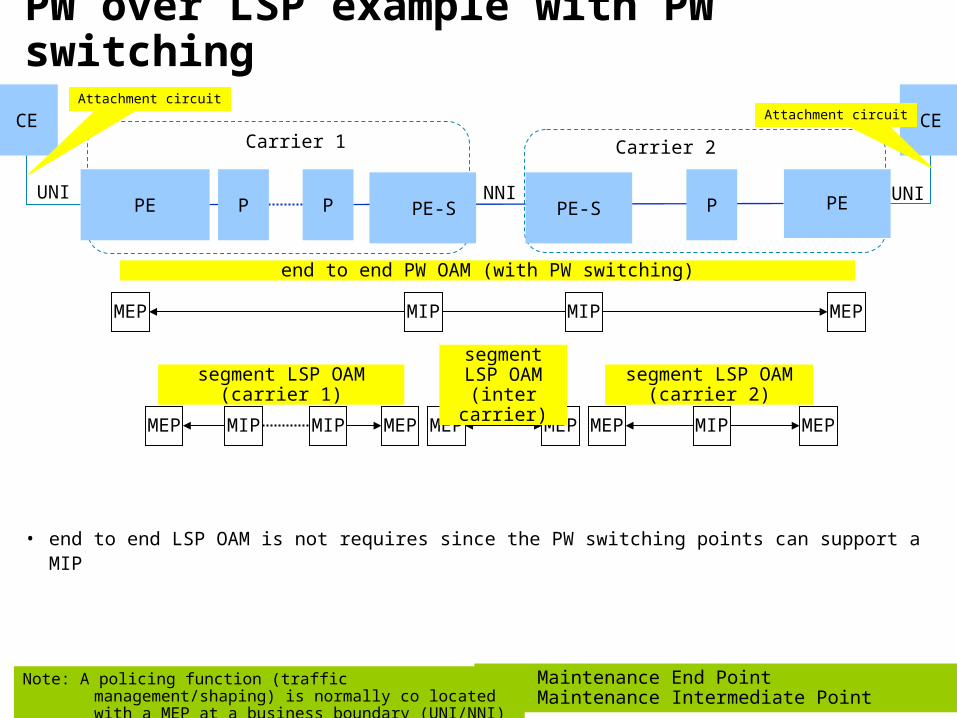
PW over LSP example with PW switching
P P
MEP MIP MIP MEP
MEP MEPMEP MEP MEP MEP MIPMIP
• end to end LSP OAM is not requires since the PW switching points can support a MIP
Carrier 1 Carrier 2
NNI
MEP: Maintenance End PointMIP: Maintenance Intermediate Point
segment LSP OAM
(inter carrier)
Note: A policing function (traffic management/shaping) is normally co located with a MEP at a business boundary (UNI/NNI)
CE CE Attachment circuit
segment LSP OAM(carrier 2)
segment LSP OAM(carrier 1)
Attachment circuit
PE
end to end PW OAM (with PW switching)
P
MIP
UNI UNI PE PE-S PE-S

39
LSP monitoring and alarming Generic Exception Label and Generic Associated Channel Proposal
Assign a Transport Alert Label as a Label For yoU (LFU) from reserved label space:Label 13 has been proposed because, Label 14 has been allocated to Y.1711
Y.1711 arch fits within “ACH” architecture Bottom of Stack is always set on LFU in the transport profile
Define a Generic Associated Channel function Similar to the PWE-3 Associated Channel but doesn’t have to be associated with a PWImportant the first nibble tells system not to load balance (so not 06 or 04)
Generic Associated Channel is always under a Generic Exception Label if endpoint (MEP) Generalised Associated Channel defines what packet function using “channel type” field
Examples : What OAM function is carried, DCC, etc
MAC Header Channel payloadL1 L2 LFU/BoS Generic ACH
0001 | Ver | Resv | Channel Type
40
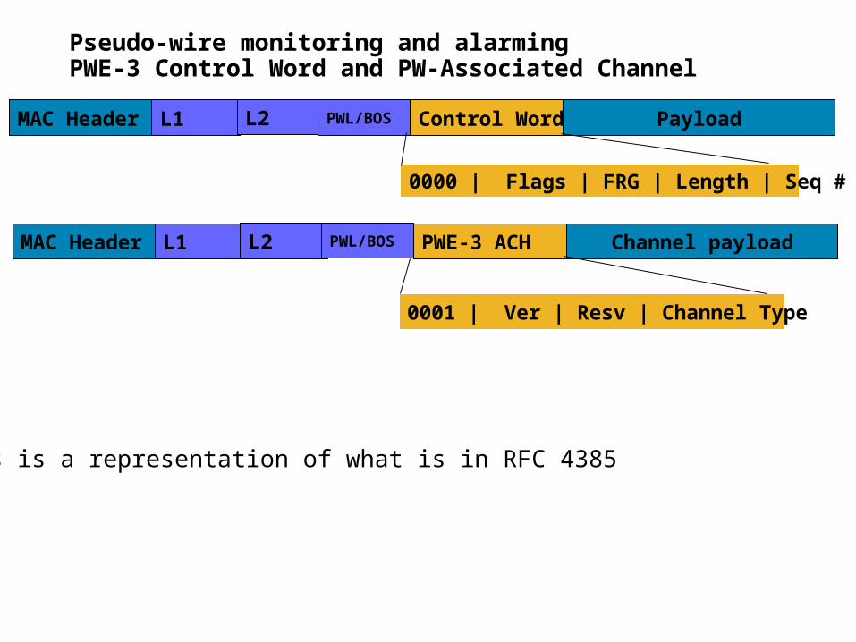
Pseudo-wire monitoring and alarmingPWE-3 Control Word and PW-Associated Channel
MAC Header Channel payloadL1 L2 PWL/BOS PWE-3 ACH
MAC Header PayloadL1 L2 PWL/BOS Control Word
0000 | Flags | FRG | Length | Seq #
0001 | Ver | Resv | Channel Type
This is a representation of what is in RFC 4385

41
Required Functionality demarked by Associated Channel CV : Connectivity Verification (detection of configuration errors) PM: Performance of the path AIS: Alarm suppression CC : Continuity Check : Is the path present (may reuse vanilla BFD here)
Light weightRole is as a CC protocol, it is not a CV protocol Not a connectivity verification protocolVCCV-BFD provides capabilities over pseudo-wire
ECCOSS and control plane communication
APSProtection switching coordination
Accounting/Billing information Security exchange Extra codepoint space to define new or use existing protocols for other
functions
42
Associated Channel Functionality Observations Existing MPLS LSP OAM uses an IP based control channel and
could be used for some OAM functions in transport networks– e.g. CC/CV
– The new Alert label based control channel should be able to co-exist with the existing MPLS LSP OAM functions and protocols
OAM message formats and protocol details carried in the OAM channel will be discussed in the design phase
– We must figure out what the OAM messages/protocols should be used for the new requirements
– Decide whether LSP-Ping or BFD can or should be tweaked or not

43
Forwarding and OAM:LSPs / PWOAM and Label Stacks

44
Scope of next slides
Slides cover on MEP to MEP and MEP to MIP monitoringDetailed OAM packet walkthrough not yet covered in this slide-set
For MIP monitoring traceroute or loopback is executed and TTL set accordingly
Introduce concept of LSP/PW TCM label:This is a label to indicate a tandem monitoring session context
Label is stacked above label of LSP or PW being monitored
1 for 1 mapping between an LSP / PW and its TCM session. i.e. no multiplexing
Need mechanism to bind TCM label to underlying LSP or PW being monitored
MEP to MIPMEP sets the TTL of the LSP, TCM or PW label so that it will expire when the target MIP is reached
PHP
No Showstoppers found

45
Notation and color conventions
• [Destination][(using label provided by)][optionalFEC]/[StackBit]
• Thus D(E)/0 means Destination is D, using label provided by (E) - i.e. c is the tunnel next hop and the Sbit is 0 - i.e. not bottom of stack.
• Thus E(E)p/1 means Destination is E, using label provided by (E) the FEC is a pseudowire and the Sbit is 1, i.e. bottom of stack
• Special Labels and termsLFU = Label For yoU - OAM alert label
Ach = Associated Channel Header
CW = Control Word
P = PW FECColor Conventions
LSP tandem OAM labelLSP labelPW tandem OAM labelPW labelPW control wordLabel For yoUACH

46
Procedural Ordering Overview
Step 1 : establish the segment LSPQuestion : can segment LSP and existing end-to-end LSP share bandwidth?
Step 2 : establish a new end-to-end LSP and which must be tunnelled in the segment LSP
Use MBB procedures (for sharing resources between existing and new end-to-end LSP).
Step 3 : Perform switchover after Resv is received in AITU-T mechanisms rely on the creation of a Protection Group between the old and new (tunnelled) end-to-end LSP, the forcing of protection switching via APS and the tearing down of the Protection Group
Step 4 : Tear down the old end-to-end LSP

47
LFU/1ACh
LFU/1ACh
LFU/1ACh
LFU/1ACh
Section OAM
TCM-LSP OAM D(C)/0 D(D)/0LFU/1ACh
LFU/1ACh
E2E (A to E)LSP OAM
D(C)/0E(B)/0 E(D)/0 E(E)/0LFU/1ACh
LFU/1ACh
LFU/1ACh
E(D)/0LFU/1ACh
E2E (A to E)PW OAM E(E)p/1
AChE(E)p/1
AChE(E)p/1
AChE(E)p/1
ACh
Non OAM Data Frames
CW CW CWCW
LFU – Label For You (label 13)ACh – Associated ChannelCW – Control Word
TCM-LSPs
E2E LSPSS-PW
A B C D E
D(D)/0
D(C)/0E(B)/0 E(D)/0 E(E)/0E(D)/0
D(D)/0
E(E)p/1 E(E)p/1 E(E)p/1E(E)p/1
D(C)/0E(B)/0 E(D)/0 E(E)/0E(D)/0
D(D)/0
SS-PW over intra-domain LSPLSP, TCM-LSP & PW OAM
TCM LSP label does not
represent a true LSP No LSP Mux (1:1
mapping)
PE PEPPP

48
Provider BProvider A
LFU/1ACh
LFU/1ACh
LFU/1ACh
LFU/1ACh
LFU/1ACh
Section OAM
TCM-LSP OAM C(B)0 C(C)/0 F(E)/0 F(F)/0LFU/1ACh
LFU/1ACh
LFU/1ACh
LFU/1ACh
E2E LSP OAM C(B)0 C(C)/0 F(E)/0 F(F)/0C(C)/0 C(C)/0 F(F)/0 F(F)/0LFU/1ACh
LFU/1ACh
LFU/1ACh
LFU/1ACh
D(D)/0LFU/1ACh
E2E PW OAM C(B)0 C(C)/0 F(E)/0 F(F)/0C(C)/0 C(C)/0 F(F)/0 F(F)/0F(F)p/1
AChF(F)p/1
AChF(F)p/1
AChF(F)p/1
ACh
D(D)/0F(F)p/1
ACh
Non OAM Data Frames C(B)0 C(C)/0 F(E)/0 F(F)/0C(C)/0 C(C)/0 F(F)/0 F(F)/0F(F)p/1
CWF(F)p/1
CWF(F)p/1
CWF(F)p/1
CW
D(D)/0F(F)p/1
CW
LFU – Label For You (label 13)ACh – Associated ChannelCW – Control Word
TCM-LSPs
E2E LSPSS-PW
A B C D E F
LSPs stitched in C and D
One hop TCM-LSP OAM and Section OAM would not usually run concurrently
SS-PW over inter-provider LSPLSP, TCM-LSP & PW OAM
PE PEPBP PB P
PB = Provider Border LSR
From DP perspective, LSP stitching is a normal label swap operation

49
MEP to MIP OAM:TTL Processing for PWs and LSPs
In order to maintain individual levels of OAM and path detectionUse pipe model per label level
TTL is not copied up the stack on a push
TTL is not copied down the stack on a pop
TTL is decremented on each swap and pop action
Traceroute for a level can be used to trap packets at each node that processes the label for that level in the label stack
Scenarios to be added:
a) LSP on FRR path (both facility and detour)
b) b) PW with ACH processing (no need for LFU, so processing steps are slightly different from LSP processing)

50
Short Pipe Model with Nested TTL and No PHP Processing
TTL=k-1
TTL=j
TTL=k-2
TTL=j
TTL=m
TTL=k-2
TTL=j
TTL=m-1
TTL=n
TTL=k-2
TTL=j
TTL=m-2
TTL=k-3
TTL=j
TTL=k-3
TTL=j
TTL=k-2
TTL=j
TTL=m-1
TTL=n-1
TTL=k
TTL=j
PWLSP1
LSP2LSP3
A B C D E F G H
Bottom of stack
Stack going into pipe Stack received at H
From the TTL perspective, the treatment for a Pipe Model LSP isidentical to the Short Pipe Model without PHP (RFC3443).

51
ECMP Considerations
OAM and Data MUST share fate.
PW OAM fate shares with PW through the first nibble mechanism (RFC4928) and hence is fate shared over any MPLS PSN.
Fate sharing is not assured for the MPLS Tunnel OAM/Data in the presence of ECMP.
The current MPLS Transport Profile ensures OAM/Data fate sharing for the MPLS tunnel by excluding the use of MPLS ECMP paths (for example by only using RSVP or GMPLS signaled MPLS tunnels)
There is a requirement to improve IETF MPLS OAM. This will require the problem of fate sharing in the presence of ECMP to be addressed.
If the OAM/DATA fate sharing problem is solved for MPLS ECMP, then the Transport Profile may be extended to take advantage MPLS paths that employ ECMP.

52
Segment LSP operations
Path diversity is not part of the OAM process. It is the responsibility of the Control or Management Plane
OAM function uses LFU with Generic Channel Association Pre-provisioned segment primary and backup paths LSP OAM running on segment primary and back-up paths (using a nested LSP) OAM failure on backup path Alert NMS OAM failure on primary path results in B and D updating LFIB to send traffic labelled for BD via
segment backup path End to End traffic labelled for BD now pushed onto segment backup path
Primary Path
LSP OAM
LFIB:AB-BC
LFIB:BC-CD
LFIB:CD-DE
PW-L, AB
DE, PW-L
LFIB:AW-WXLFIB:WX-XY
LFIB:XY-YZAE
Segment Backup Path
PW-L, AW
YZ, PW-L
Segment Primary PathB
D

53
End to End LSP operations
Path diversity is not part of the OAM process. It is the responsibility of the Control Plane
OAM function uses LFU with Generic Channel Association Pre-provisioned primary and backup paths LSP OAM running on primary and back-up paths OAM failure on backup path Alert NMS OAM failure on primary path A and E updating LFIB to send and receive PW-L
traffic over backup path
LSP OAM
LSP OAM
LFIB:AB-BC
LFIB:BC-CD
LFIB:CD-DE
PW-L, AB
DE, PW-L
LFIB:AW-WXLFIB:WX-XY
LFIB:XY-YZAEPrimary Path
Backup Path
PW-L, AW
YZ, PW-L

54
Control Plane

55
Conclusions/Recommendations
Control plane sub-team sees no show-stoppers
Existing IETF protocols can be used to provide required function
Transport network operation
DCN/SCN operation
IETF GMPLS protocols already applied to ASON architecture
Any protocol extensions needed will be easy to make
Configuration of MEPs/MIPs and activation of monitoring
Support of bridge and roll capability
Allows Tandem connection monitoring to be added to an existing LSP without disruption to the service

56
Discussion
Transport profile should meet the requirements of the ASON architectureUse IETF protocol suite given it is used for ASON
GMPLS RSVP-TE for LSP signaling
GMPLS OSPF-TE and ISIS-TE for LSP TE information distribution
LDP will be used for PW setup (as part of client set up process)
DCN/SCNIP-based DCN/SCN
ACH defines ECC
Can have as many channels and protocols as necessary and therefore could support the SCN
Must have policing for DCN/SCN
IS-IS or OSPF running in DCN to provide DCN topology information
Connectivity discovery and verificationCould use LMP if native mechanisms not adequate

57
Provider BProvider A
Data Frames C(B)/0 C(C)/0 F(E)/0 F(F)/0F(C)p/1
CWF(C)p/1
CWF(F)p/1
CWF(F)p/1
CW
D(D)/0F(D)p/1
CW
LSP tunnel
MS-PW
A B C D E F
Control Plane View ofInter-provider MS-PW
S-PES-PE T-PET-PE
CP CP CP CP CP CP
PW-Segment A
LSP-Tunnel A
PW-Segment B
LSP-Tunnel B
SCN GW
PW-Seg. AB
SCN-ASCN-A SCN-BSCN-B
RSVP-TE RSVP-TE
T-LDP
RSVP-TE
T-LDP
RSVP-TE
T-LDP
RSVP-TE
T-LDP
RSVP-TE
LSP-
Tunnel
AC E-NNI ACI-NNI I-NNI I-NNI I-NNI
AC – Attachment CircuitNNI – Network-Network InterfaceI-NNI – Internal NNIE-NNI – External NNISCN – Signaling Communication NetworkSCN-GW GatewayT-LDP – Targeted LDP
C1 C2
RSVP-TE

58
Provider BProvider A
A B C D E F
ASON Call/ConnectionModel
S-PES-PE T-PET-PE
CP CP CP CP CP CP
Connection Segment A
Call Segment A
SCN GW
Con.-Seg. AB
SCN-ASCN-A SCN-BSCN-B
CCA CCB
NCCA
CCC
NCCC
CCD
NCCB
CCF
NCCB
CCE
Call
Segmt.
UNI E-NNI UNII-NNI I-NNI I-NNI I-NNI
CCC1
CCCC1
CCC2
CCCC2
Con. Segmt.
Call
Segmt.
Connection Segment B
Call Segment BCon.
Segmt.
Call
Segmt.
Call Signaling
Connection Signaling
CCC – Client Call ControllerNCC – Network Call ControllerCC – Connection ControllerUNI – User-Network-InterfaceNNI – Network-Network InterfaceI-NNI – Internal NNIE-NNI – External NNI
C1 C2

59
Survivability

60
Advice
Survivability sub team has not found any issues that prevent the creation of an MPLS transport profile
No showstoppers found
Therefore option 1 can be selected
Summary of discussion– Three potential solutions have been identified
– Each solutions has different attributes and advantages
– Further work in the design phase should eliminate one or more of these options and/or provide an applicability statement

61
Discussion
Nested LSPs (potentially PWEs) provide levels of hierarchy to support per segment and path recovery
Must draw up PWE requirements
Most of the time intermediate nodes do not process the entire stack
Each segment can act independentlyMultiple potential solutions including
Native IETF mechanisms
Carry G.8131/G.8132 PDUs in an ACH

62
Discussion - 2
Native MPLS protection schemes, such as facility bypass and detours, can be used to provide ring protection in most, but not optimal in some scenarios
A single facility bypass LSP protects all LSPs over a specific link by wrapping traffic
A detour LSP can be used for optimal traffic delivery to the egress point (without wrapping)
A detour LSP is needed for every LSP to be protected.
Also can provide optimized exit preventing the 2x bandwidth in other wrapping repair technologies
Must add notion of DOWN and ADMINDOWN (e.g. standby bit)
ITU-T G.8132 TM-SPRing defines a ring protection that includes additional capabilities to the MPLS protection schemes, by supporting coordinated protection in case of multiple failures (using single protection mechanism for all cases
MPLS ring protection strategies provide necessary functionality and option 1 can be recommended but, there appears to be cases where G.8132 may provide additional functionality that may be incorporated and specified
We have found no showstoppers

63
Network Management

64
Advice
Network Management sub team has not found any issues that prevent the creation of an MPLS transport profile
Therefore option 1 can be selected
No Showstoppers found

65
ITU-T PM objectives
PM Requirements for a MPLS-TP LSP/PW
Same measurements and processing as Ethernet– Connectivity defects present in a 1-second period
– number of lost (circuit/packet) frames in a 1-second period
– near-end and far-end (severely) errored second
– 10 seconds being severely errored/not severely errored to enter/exit unavailable time (UAT)
– 15min and 24hr PM parameter reporting
To define how LM (loss measurement) and DM (delay measurement) information, as defined in Y.1731 & draft G.8114, is registered in 15min/24hr bins (G.7710)
Dependent on OAM providing the primitives to make these measurementsDependent on OAM providing the primitives to make these measurements

ITU-T Y.1731 Fault notification through Alarm Indication Signal Performance monitoring
Frame Loss Ratio Frame Delay Frame Delay Variation
IEEE 802.1ag and ITU-T Y.1731: Fault detection through Continuity Check Messages Fault verification through Loopback and reply messages Fault Isolation through Linktrace and reply messages

67
Summary

68
Summary
To date we have found no showstoppers and everyone is in agreement that we have a viable solution
Recommend Option 1
It is technically feasible that the existing MPLS architecture can be extended to meet the requirements of a Transport profile
The architecture allows for a single OAM technology for LSPs, PWE and a deeply nested network
From probing various SGs, WGs it appears that label 14 has had wide enough implementation and deployment that the solution may have to use a different reserved label (e.g. Label 13)
Extensions to Label 14 should cease
This architecture also appears to subsume Y.1711 since the requirements can be met by the mechanism proposed here


![1 TM8106 Optical Networking Multi-Protocol Label Switching-Transport Profile (MPLS-TP) By Ameen Chilwan Syllabus: [1] MPLS Transport Profile (MPLS-TP):](https://img.pdfslide.us/doc/110x75/56649c9d5503460f9495c9d2/1-tm8106-optical-networking-multi-protocol-label-switching-transport-profile.jpg)