Embed Size (px)
Citation preview

2013 Moxa Inc. All rights reserved.
P/N: 1802012800011
Moxa ICF-1280I Series Industrial PROFIBUS-to-Fiber
Converter Hardware Installation Guide
First Edition, November 2013

- 2 -
Introduction
The ICF-1280I series PROFIBUS-to-fiber converters are based on the PROFIBUS DP standard, and are compliant with EN 50170. The converters are mainly used to extend the transmission distance of PROFIBUS devices over optical fiber, and provide redundant transmission. More specifically the ICF-1280I series converts PROFIBUS signals between copper and fiber wires, and extends PROFIBUS transmission up to 4 km (for multi-mode models) or up to 45 km (for single-mode models). In addition, the ICF-1280I series converters have dual fiber ports that can be used to form a ring topology for redundant transmission, and avoid package lost when a fiber path is broken. The ICF-1280I converter also provides 2 kV isolation protection for the PROFIBUS system and dual power inputs to ensure uninterrupted operation.
The ICF-1280I series converters are uniquely designed with Remote Fiber Diagnosis that eliminates the need for a fiber optic sensor by using DIP switch adjustments instead. Remote Fiber Diagnosis can detect fiber connections for the overall topology from any individual converter, and determine which side (Tx or Rx) is causing the problem for the converter.
Why Convert PROFIBUS to Fiber?
Optical fiber communication not only extends the communication distance, but also provides the following advantages:
• Immunity to electrostatic interference: Fiber is immune to electromagnetic interference and radio frequency interference. It provides a clean communication path and is immune to cross-talk.
• Insulation: Optical fiber is an insulator interface; the glass fiber eliminates the need for using electric currents as the communication medium.
• Security: Fiber cannot be tapped by conventional electric means and is very difficult to tap into optically while radio and satellite communication signals can be captured easily for decoding.
• High reliability and low maintenance: Fiber wires are immune to adverse temperature and moisture conditions. As a result, they do not corrode or lose signals, and are not affected by short circuits, power surges, or static electricity.
Auto/Manual Baudrate Settings
The ICF-1280I series converters simply convert the signal back and forth between PROFIBUS and fiber at baudrates between 9.6 Kbps to 12 Mbps. Engineers do not need to know the baudrate of the connected PROFIBUS device; the ICF-1280I series converters can automatically detect the baudrate of the PROFIBUS device and apply this baudrate directly. This is an extremely convenient feature. If necessary, baudrates can be set to a fixed value via DIP switches to shorten the baudrate detection period when the system initializes.
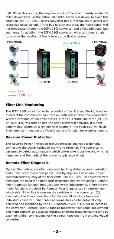
PROFIBUS Fail Safe
Electrical noise may be generated when a PROFIBUS device malfunctions or the serial interface fails, resulting in bus failure. Traditional media converters transmit noise signals through the fiber wire to the other converter. This not only disrupts data communication between the two buses, but will also bring communication across the entire system to a
- 3 -
halt. When this occurs, the engineers will not be able to easily locate the failed device because the entire PROFIBUS network is down. To avoid this situation, the ICF-1280I series converter has a mechanism to detect and recognize noise signals. If the bus fails on one side, the noise signal will not propagate through the ICF-1280I converter and affect additional bus segments. In addition, the ICF-1280I converter will also trigger an alarm to provide the location of the failure to the field engineer.
Fiber Link Monitoring
The ICF-1280I series converter provides a fiber link monitoring function to detect the communication errors on both sides of the fiber connection. When a communication error occurs, a red LED status indicator (P1, P2, or Fault LED) will turn on and the relay alarm will activate. If a fiber abnormality occurs on a remote fiber segment, the Fault LED will flash. Engineers can then use the Fiber Diagnosis function for troubleshooting.
Reverse Power Protection
The Reverse Power Protection feature protects against accidentally connecting the power cables to the wrong terminal. The converter is designed to detect automatically which power wire is positive and which is negative, and then adjust the power supply accordingly.
Remote Fiber Diagnosis
Optical fiber cables are often deployed for long distance communication and a fiber optic inspection pen is used by engineers to ensure proper communication quality of the fiber cable. The ICF-1280I series converters eliminate the need for a fiber optic inspection pen by providing a Remote Fiber Diagnosis function that uses DIP switch adjustments. There are two major functions provided by Remote Fiber Diagnosis: (1) determining which side (Tx or Rx) is causing the problem on the converter; (2) examining the fiber connections for the overall topology from any individual converter. Fiber cable abnormalities can be automatically detected and identified by the LED indicator even if it is not adjacent to the converter. Remote Fiber Diagnosis facilitates fiber cable deployment and management, and also significantly shortens troubleshooting time by examining fiber connections for the overall topology from any individual converter.

- 4 -
Using Remote Fiber Diagnosis:
Set DIP switch SW8 to the ON position on any ICF-1280I converter and see the Ready LED status. A flashing green Ready LED indicates that the Fiber Diagnosis has finished. The Fault LED indicates the location of the fiber connection abnormality. The P1 or P2 LED indicates which side (Tx or Rx) is causing the problem. The Fault LED will shine a steady red to indicate an adjacent fiber connection error, or flash red to indicate a non-adjacent fiber connection error. If there are no fiber connection errors in the entire topology, the related LEDs will shine green or remain OFF. If the fiber connection error is adjacent to the converter, the status will also be indicated by the P1 (Port 1) or P2 (Port 2) LEDs. A flashing red light on P1 (or P2) means that the Rx fiber cable connected to this port is broken. Similarly, a solid red light on P1 (or P2) means that the Tx fiber cable in this port is broken. If the fiber connection error is not adjacent to the converter (i.e., the fiber cables connected to this converter are working properly), the Fault LED will flash red. As a result, you should run Remote Fiber Diagnosis on every other (second) converter in the topology to recursively troubleshoot the problem. Further descriptions and troubleshooting can be found in the Troubleshooting table.
Redundant Ring
The ICF-1280I series converters can connect PROFIBUS devices in a redundant ring topology. Use the DIP switch to configure all the ICF- 1280I converters to Redundant Ring mode. When a PROFIBUS master transmits a signal from one converter to the PROFIBUS slave devices, this signal will travel to all the converters around the ring until it returns to the original converter and terminate.
How to form a redundant ring topology:
To form a redundant ring topology, connect the Tx Port (Port 1) on the first ICF-1280I converter to the Rx Port (Port 2) on the following converter. Then, connect the Tx Port (Port 2) on the first ICF-1280I converter to the Rx Port (Port 1) on the preceding converter. Similarly, connect the Rx Port (Port 1) on the first ICF-1280I converter to the Tx Port (Port 2) on the following converter. Then, connect the Rx Port (Port 2) on the first ICF-1280I converter to the Tx Port (Port 1) of the preceding converter.

- 5 -
Features
• Redundant Ring mode for fiber communication backup with zero recovery time
• Remote Fiber Diagnosis • Auto baudrate detection and data speeds up to 12 Mbps • PROFIBUS bus fail safe • Alarm by relay output • Provide 2 kV galvanic isolation • Power polarity protection • Extend PROFIBUS transmission distance:
Up to 45 km with single-mode (ICF-1280I-S models) Up to 4 km with multi-mode (ICF-1280I-M models)
• Point-to-point, linear (bus), star, and redundant ring topologies • Dual power input for redundancy • Wide operating temperature from -40 to 75°C (for “-T” models)
Package Checklist
Before installing the ICF-1280I converter, verify that the package contains the following items:
• ICF-1280I PROFIBUS-to-fiber converter • Hardware installation guide • Warranty card
NOTE: Please notify your sales representative if any of the above items are missing or damaged.
Mounting Dimensions (Unit: mm)
ICF-1280I

- 6 -
Top View
Front View
ATTENTION
Electrostatic Discharge Warning!
To protect the product from damage due to electrostatic discharge, we recommend wearing a grounding device when handling your ICF-1280I series converters.
Mounting
The aluminum DIN-rail attachment plate should be fixed onto the back panel of the ICF-1280I converter when you take it out of the box. If you need to reattach the DIN-rail attachment plate to the ICF-1280I converter, make sure the stiff metal spring is situated towards the top, as shown in the figures below. STEP 1: Insert the top of the DIN rail into the slot just below the stiff metal spring.
STEP 2: The DIN-rail attachment unit will snap into place as shown below.
To remove the ICF-1280I series converter from the DIN rail, simply reverse Steps 1 and 2 above.

- 7 -
Fiber Cable
ST-Port Pinouts ST-Port to ST-Port Cable Wiring
PROFIBUS Pin Assignment
PIN Signal Name 1 N.C. 2 N.C. 3 PROFIBUS D+ 4 RTS 5 Signal common 6 5 V 7 N.C. 8 PROFIBUS D- 9 N.C.
Federal Communications Commission Statement
This device complies with part 15 of the FCC Rules. Operation is subject to the following two conditions:
1. This device may not cause harmful interference, and 2. This device must accept any interference received, including
interference that may cause undesired operation.
Slot Time Settings
Although ICF-1280I series converters can be connected in different topologies with a large number of units, the total cable length and network topology can give rise to frame delays. A sufficient slot time is required to prevent the PROFIBUS master from timing out. Engineers are recommended to set the PROFIBUS master’s slot time according to the following formulas. For linear and star topologies:
Slot time = A + B × L + 13 × N
Transmission Speed (kbps) A B 12000 811 120 6000 461 60 3000 261 30 1500 161 15 500 111 5 187.5 71 1.875 93.75 71 0.9375 45.45 411 0.4545 19.2 71 0.192 9.6 71 0.096

- 8 -
For redundant ring topology:
Slot time = A + B × L + C × N
L: The length of the fiber optic in kilometer.
N: The number of converters in the system.
A, B, and C: Parameters set according to different baudrates.
*To avoid frame conflicts, it is recommended to set the PROFIBUS command retry limit ≥ 3, and the slot time < 262128.
DIP Switch Settings
There are 8 DIP switches on the top panel of the ICF-1280I series converter. All DIP switches except SW5 are set to the factory default OFF position.
Transmission Speed (kbps) A B C 12000 1651 240 28 6000 951 120 24 3000 551 60 24 1500 351 30 24 500 251 10 24 187.5 171 3.75 24 93.75 171 1.875 24 45.45 851 0.909 24 19.2 171 0.384 24 9.6 171 0.192 24
Transmission Speed (kbps) SW1 SW2 SW3 SW4 Auto (default) OFF OFF OFF OFF 12000 OFF OFF OFF ON 6000 OFF OFF ON OFF 3000 OFF OFF ON ON 1500 OFF ON OFF OFF 500 OFF ON OFF ON 187.5 OFF ON ON OFF 93.75 OFF ON ON ON 45.45 ON OFF OFF OFF 19.2 ON OFF OFF ON 9.6 ON OFF ON OFF
Setting ON OFF SW5 Fiber Link Monitor Disable SW8 Remote Fiber Diagnosis* Disable
Topology SW6 SW7 Linear, Star (P1/P2 enable) OFF OFF Linear, Star (P1 disable) OFF ON Linear, Star (P2 disable) ON OFF Redundant Ring ON ON In Redundant Ring mode, the Fiber Link Monitor function should also be enabled. Set SW5 to the ON position. For point-to-point topology with

- 9 -
LED Indicators
There are 7 LED indicators on the front panel of the ICF-1280I.
LED Color Description Relay Status
PWR1/PWR2
Solid green
Power is on Closed
Off Power is off, or power error condition exists
Open
Ready
Solid green
Baud rate is detected, converter is ready for communication
Closed
Flashing green*
Fiber diagnosis is finished Closed
Flashing red*
Detecting baudrate. Closed
Flashing red and green*
Slotting time setting error Closed
Off System power is off Closed
P1/P2 (Fiber)
Flashing/solid green
Fiber port is receiving data Closed
Solid red*
Fiber cable linking to Tx is abnormal
Open
Flashing red*
Fiber cable linking to Rx is abnormal
Open
Off Fiber in idle state Closed
P3 (PROFIBUS)
Flashing green
PROFIBUS port is communicating
Closed
Flashing red
Inner transceiver IC defective; PROFIBUS port data communication error; insufficient shielding of the bus cable; echo package timeout
Open
Solid red Echo package timeout, PROFIBUS UART character error
Open
Off PROFIBUS in idle state Closed
Fault
Solid green
Fiber connections are working normally in Fiber Diagnosis mode
Closed
Flashing red*
Fiber abnormality occurred in another segment
Closed
Solid red*
Fiber abnormality occurred on this converter
Closed
If both power inputs experience an outage, the relay will become an open circuit for alarm purposes. *Refer to the following table for troubleshooting.
redundant fiber cables, set both converters to Redundant Ring mode with the correct slot time setting. *Refer to the Remote Fiber Diagnosis section for instructions. If an ICF-1280I converter is deployed at the beginning or at the end of the topology in Linear mode or Star mode, the unused port should be disabled. In such cases, it is recommended to use an ICF-1180I series converter. Please use the ICF-1180I series with Rev. 1.3, or higher versions to connect with the ICF-1280I series.
- 10 -
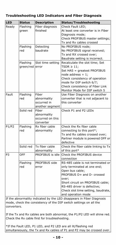
Troubleshooting LED Indicators and Fiber Diagnosis
LED Status Description Status/Troubleshooting Ready Flashing
green Fiber diagnosis finished
Check Fault LED; At least one converter is in Fiber Diagnosis mode; Check PROFIBUS master settings; Tx and Rx cables crossed
Flashing red
Detecting baudrate
No PROFIBUS node; No PROFIBUS signal received; Tx and RX crossed over; Baudrate setting is incorrect.
Flashing green/red
Slot time setting error
Recalculate the slot time; Set TSDR ≥ 11; Set HAS = greatest PROFIBUS node address + 1; Check consistency of operation mode for DIP switch 6/7; Check consistency of Fiber Link Monitor Mode for DIP switch 5
Fault Flashing red
Fiber abnormality occurred in another segment
Use Fiber Diagnosis on another converter that is not adjacent to this converter
Solid red Fiber abnormality occurred on this converter
Check P1 and P2 LEDs
P1/P2 Flashing red
Rx fiber cable abnormality
Check the Rx fiber cable connecting to this port*; Tx and Rx cables crossed over; Partner module is powered OFF or defective
Solid red Tx fiber cable abnormality
Check the fiber cable linking to Tx of this port*
P3 OFF PROFIBUS is idle Check the PROFIBUS device connection
Flashing red
PROFIBUS side error
RS-485 cable is not terminated or only terminated at one end; Open bus cable; PROFIBUS D+ and D- crossed over; Short circuit on PROFIBUS cable; RS-485 driver is defective; Check slot time setting, baudrate, and operation mode
If the abnormality indicated by the LED disappears in Fiber Diagnosis mode, check the consistency of the DIP switch settings on all the converters. If the Tx and Rx cables are both abnormal, the P1/P2 LED will shine red. Check the Rx cable first for troubleshooting. *If the Fault LED, P1 LED, and P2 LED are all lit/flashing red simultaneously, the Tx and Rx cables of P1 and P2 may be crossed over.

- 11 -
ATTENTION
This is a Class 1 laser/LED product. Do not stare into the laser beam.
Specifications
PROFIBUS Communication PROFIBUS Interface PROFIBUS DP Number of Ports 1 Connector DB9 female Isolation Protection 2 kV Baudrate 9.6, 19.2, 45.45, 93.75, 187.5, 500 Kbps,
1.5, 3, 6, 12 Mbps Auto Baudrate Yes Compliant with EN 50170 Fiber Communication Connector type ST Number of Ports 2 Distance Single-mode fiber for 45 km
Multi-mode fiber for 4 km Support Cable:
Single-mode Multi-mode
8.3/125, 8.7/125, 9/125 or 10/125 μm 50/125, 62.5/125, or 100/140 μm
Wavelength ICF-1280I-S: 1310 nm ICF-1280I-M: 820 nm
Tx Output
ICF-1280I-S: -7 dBm ICF-1280I-M: -14 dBm
Rx Sensitivity ICF-1280I-S: -29 dBm ICF-1280I-M: -28 dBm
Link Budget ICF-1280I-S: 21 dBm ICF-1280I-M: 14 dBm
Transmission Half duplex Signal delay time (any input/output)
6.5 tbit
Environmental Operating Temperature 0 to 60°C (32 to 140 °F)
-40 to 75°C (-40 to 167 °F) for T Models Storage Temperature -40 to 75°C (-40 to 167 °F), Ambient Relative Humidity 5 to 95% (non-condensing) Atmospheric pressure Up to 2000 m (795 hPa), higher altitudes
on demand

- 12 -
Power Input Power Voltage 12 to 48 VDC Connector Terminal block Power Line Protection IEC 6000-4-5 Level 3 (2 kV) Surge
Protection Power Polarity Protection Protects against V+/V- reversal Support over Currents Protection
1.1 A
Power Consumption Single mode: 165 mA @24 V Multi mode:140 mA @24 V
Relay Output Supports 1 digital output relay to alarm (Normal: close) Current carrying capacity: 2 A@30 VDC
Mechanical Dimensions (W × H × D) 39 × 115 × 70 mm Material Aluminum (1 mm) Gross Weight 225 g Regulatory Approvals Safety UL 508; EN 60950-1 EMC CE; FCC Part 15, sub part B, Class A EMI EN 55022, Class A; EN 55024 EMS EN 61000-4-2 (ESD), Level 2
EN 61000-4-3 (RS), Level 3 EN 61000-4-4 (EFT), Level 4 EN 61000-4-5 (Power Surge), Level 3 EN 61000-4-6 (CS), Level 3 EN 61000-4-8(PFMF), Level 1
Freefall IEC 60068-2-32 MTBF 792,085 hrs Green product RoHS, CRoHS, WEEE
Technical Support Contact Information www.moxa.com/support
Moxa Americas: Toll-free: 1-888-669-2872 Tel: 1-714-528-6777 Fax: 1-714-528-6778
Moxa China (Shanghai office): Toll-free: 800-820-5036 Tel: +86-21-5258-9955 Fax: +86-21-5258-5505
Moxa Europe: Tel: +49-89-3 70 03 99-0 Fax: +49-89-3 70 03 99-99
Moxa Asia-Pacific: Tel: +886-2-8919-1230 Fax: +886-2-8919-1231