Embed Size (px)
Citation preview
WORKING CHAIN –by J.Tillema This "how-to" is intended for people who know all basis principles of Inventor These tutorial have been made by means of Inventor 10. (Sorry for al bad language … I remain Dutch and I’m proud about that! :-p)
We start with a standard part, leave the first sketch and begin by making a workplane. Whit this workplane we can control the chain. For this example I have assumed a distance (off set of the workplane) 300 mm. Then we make a sketch like the one below. Pay attention especially to the workplane, these have been dragged in the model browser so that is now under the sketch, and as a result can the geometry be projected. Also we give the dimension of projective centerpoint to the projective workplane. This dimension is a so called “driven dimension”. Inventor indicates that his
selves when you creating it. Hereafter we leave the sketch and we make the origin yz plane visible. We will lay down a workpoint at the intersection of the yz plane and the lower sketch line (see picture below).
Hereafter I made a new user parameter with the name "start" and as Equation the reference parameter of 300 (in my case d5). This was the (reference) parameter from the sketch between the workplane and the centerpoint.
Next step is to copy our workpoint with a rectangular copy pattern. We select the workpoint as feature and as path the made sketch. The number remains 2 and the spacing become our parameter "start". Furthermore must clicked on “>>” , so that there its own start position can be chosen. In this case you need to select the workpoint as start point. If it is ok, you see a workpoint a preview @ our workplane appearing.
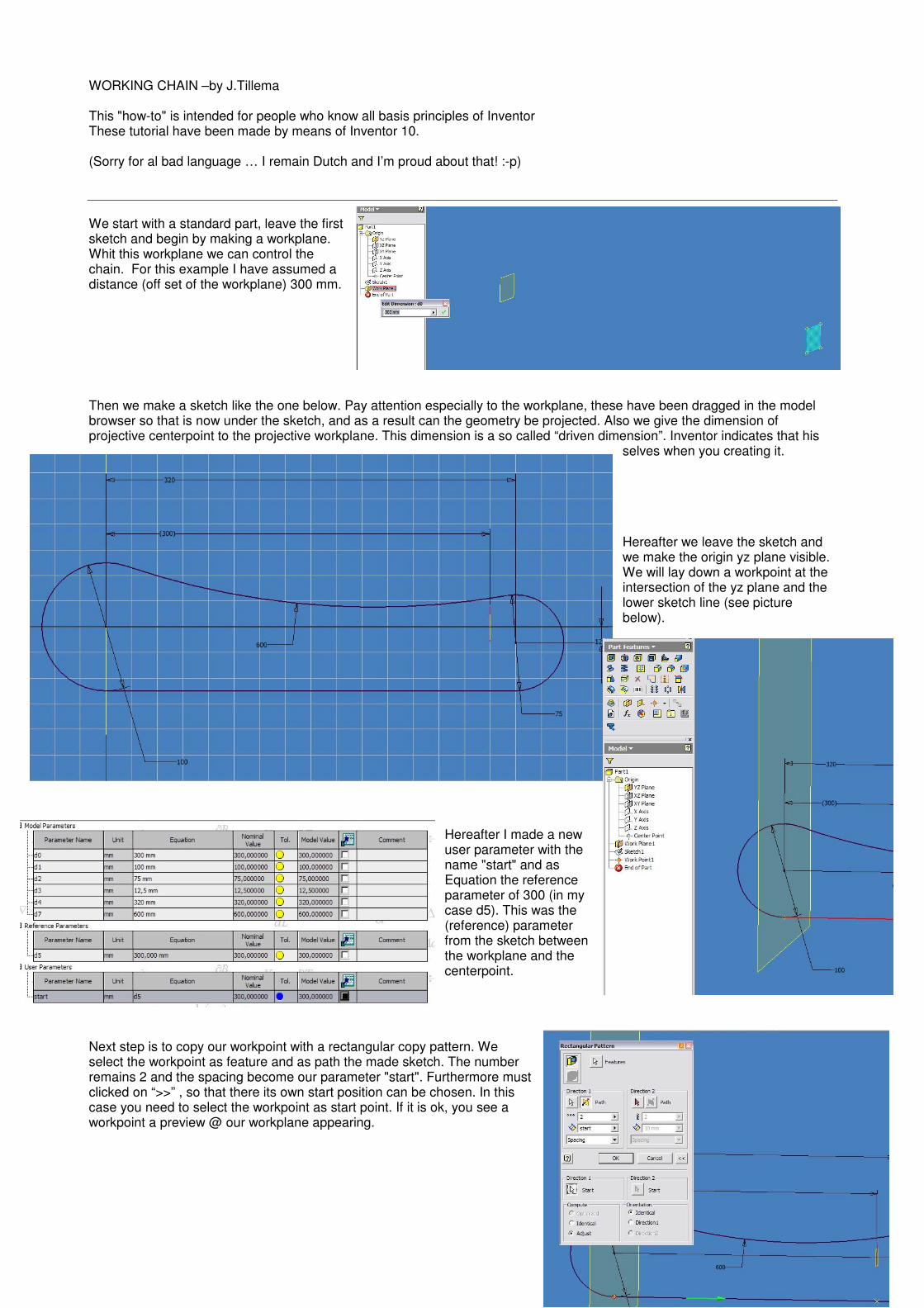
Hereafter we make our workplane adaptive. The big trick. We now make our 2nd rectangular pattern. This time we selects the 2nd workpoint (you have to obtain it from the 1st pattern) and catches we the sketch as path (again). Instead of spacing I choose for "curve length " what implies that inventor self divides the workpoints right. I have tried a couple of time’s . The number you choose is also the number of link’s you want. I choose 61 links because now the spacing distance was approach 15 mm. Further adjustments (under the
“>>” button!) Choose the earlier selected workpoint (nr 2) as start point AND also check the boxes Adjust and Direction1 (important!!). Measure now at last the distance on a right piece between 2 workpoints. In our case is that 15.07 mm. This means that our link must be about 15.07 (mm) long. This is,
because it is for presentation aims, not so precise. 15 mm must be just as good ;-) The last step for the assembly, is making the link. Because I want some rest, and I think you all can do this yourselves i don’t explain this part. I just got two things to say: you must pay attention to the length off the link (in our case 15 mm) and that there is a workpoint in the heart of the link.
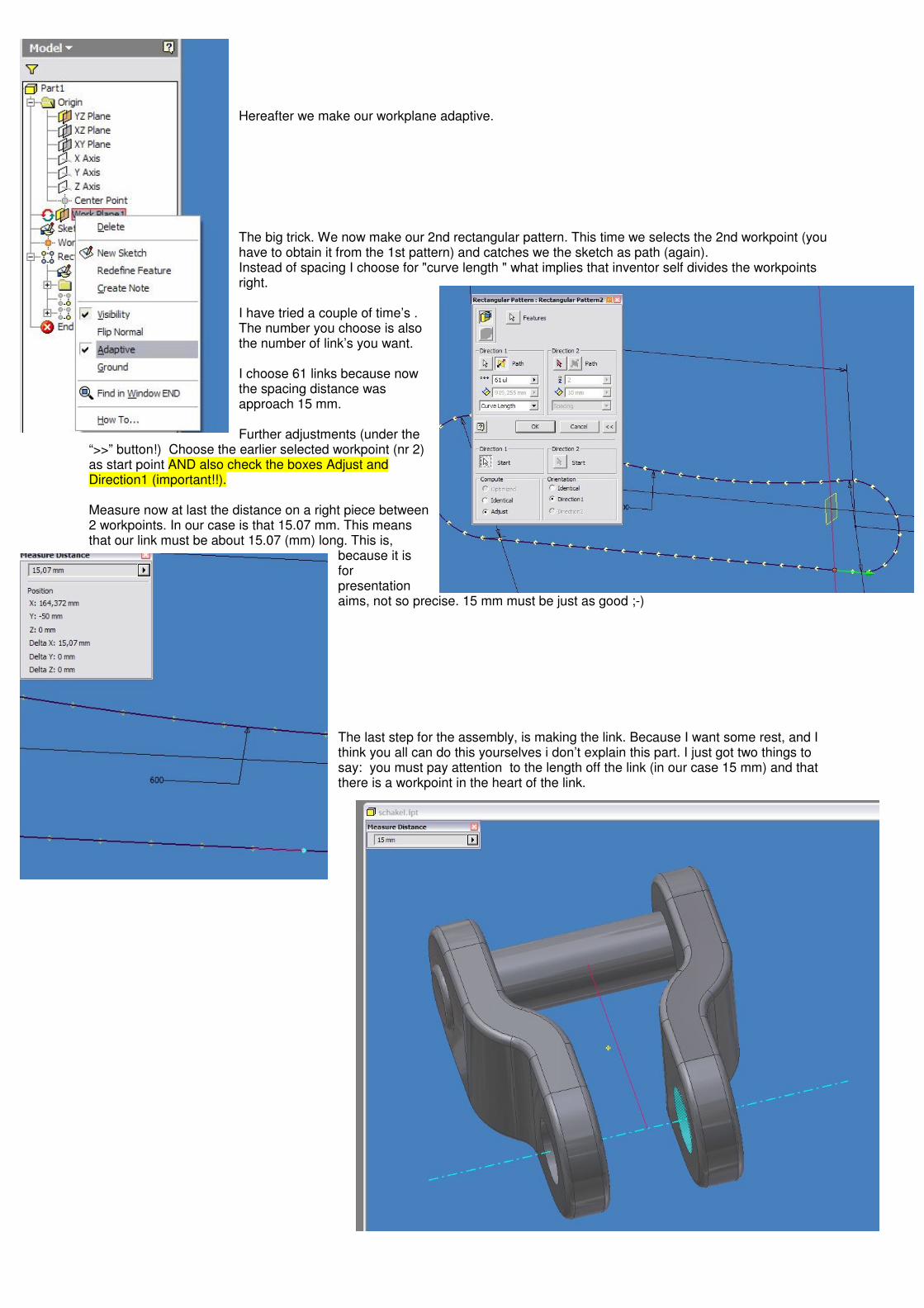
Time for the assembly. Insert as first your "master" sketch and immediately de-ground it , and while you’re at , make it also adaptive. After this the part must be constraint. Constraint all orgin assembly planes on all origin part planes. Easy one.. Hereafter make a mate constraint on workplane 1(the adaptive one) of our part and the yz plane of the assembly. Give as a offset a value of 300. Hereafter it is smart to just open your sketch of your masterpart and check if the driven dimension of 300 from the beginning is still there. If something has been incorrect constraind there now will be a value off -300. if that is remove and re-make the driven dimension Don’t forget afterwards to also adjust our parameter “start”
Hereafter we add 1 link and constrain it at whit his centerpoint on workpoint nr2 (the basis of pattern nr2). Fully constrain the link whit another 2 constrains. Change in the model browser the assembly view to modeling view. Almost there! Now click on "Pattern component" and select the link as a component, and choose for Feature pattern, from your model browser, the 2nd rectangular pattern. Taaaadaaa!! Beautiful isn’t? Hereafter you can put all sketches and workfeatures on visibility off.
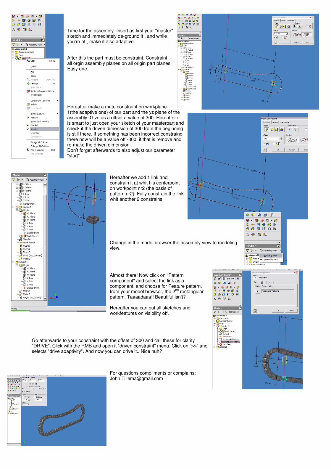
Go afterwards to your constraint with the offset of 300 and call these for clarity "DRIVE". Click with the RMB and open it "driven constraint" menu. Click on “>>” and selects "drive adaptivity". And now you can drive it.. Nice huh?
For questions compliments or complains: [email protected]