Embed Size (px)
Citation preview

Drive Technology \ Drive Automation \ System Integration \ Services
Operating Instructions
MOVI-SWITCH® 1EM
Edition 02/2012 19424426 / EN

SEW-EURODRIVE—Driving the world

Contents
Contents1 General Information ............................................................................................ 5
1.1 Use of this documentation .......................................................................... 51.2 Structure of the safety notes ....................................................................... 51.3 Rights to claim under limited warranty ........................................................ 61.4 Exclusion of liability..................................................................................... 61.5 Copyright..................................................................................................... 61.6 Product names and trademarks.................................................................. 6
2 Safety Notes ........................................................................................................ 72.1 Preliminary information ............................................................................... 72.2 General ....................................................................................................... 72.3 Target group ............................................................................................... 72.4 Designated use ........................................................................................... 72.5 Other applicable documentation ................................................................. 82.6 Transportation, storage............................................................................... 82.7 Installation................................................................................................... 82.8 Electrical connection ................................................................................... 92.9 Safe disconnection...................................................................................... 92.10 Operation .................................................................................................... 9
3 Unit Structure .................................................................................................... 103.1 MOVI-SWITCH® 1EM drive ...................................................................... 103.2 MOVI-SWITCH® 1EM with Binary Control................................................ 113.3 MOVI-SWITCH® 1EM with AS-Interface................................................... 123.4 Operating principle.................................................................................... 133.5 Type designation MOVI-SWITCH® 1EM drive.......................................... 143.6 Type designation MOVI-SWITCH® 1EM motor starter ............................. 15
4 Mechanical Installation..................................................................................... 164.1 General information .................................................................................. 164.2 Installation requirements........................................................................... 164.3 Mounting the MOVI-SWITCH® drive......................................................... 174.4 Installation in damp locations or in the open............................................. 174.5 Tightening torques .................................................................................... 18
5 Electrical Installation ........................................................................................ 195.1 Installation instructions.............................................................................. 195.2 Connecting MOVI-SWITCH® 1EM with binary control.............................. 245.3 Connecting MOVI-SWITCH® 1EM with AS-Interface ............................... 255.4 KND3 option (power plug connector) ........................................................ 28
6 Startup................................................................................................................ 296.1 Important notes on startup ........................................................................ 296.2 Requirements............................................................................................ 296.3 Startup MOVI-SWICH® 1EM with binary control....................................... 306.4 Starting up MOVI-SWICH® 1EM with AS-Interface .................................. 30
Operating Instructions – MOVI-SWITCH® 1EM
3
4
Contents
7 Operation ........................................................................................................... 337.1 Operating display of MOVI-SWITCH® 1EM with binary control ................ 337.2 Operating displayMOVI-SWITCH® 1EM with AS-Interface....................... 34
8 Service ............................................................................................................... 358.1 Diagnosing MOVI-SWITCH® 1EM with binary control .............................. 358.2 Diagnosing MOVI-SWITCH® 1EM with AS-Interface................................ 358.3 SEW Service............................................................................................. 368.4 Inspection/maintenance ............................................................................ 378.5 Shutdown .................................................................................................. 378.6 Storage ..................................................................................................... 378.7 Disposal .................................................................................................... 37
9 Technical Data................................................................................................... 389.1 CE marking and C-Tick............................................................................. 389.2 Technical data of MOVI-SWITCH® 1EM with binary control..................... 399.3 Technical data of MOVI-SWITCH® 1EM with AS-Interface ...................... 40
10 Declaration of Conformity ................................................................................ 41
11 Address List ...................................................................................................... 42
Index................................................................................................................... 53
Operating Instructions – MO
VI-SWITCH® 1EM
1Use of this documentationGeneral Information
MOVI-SWITCH® 1EM1 General Information1.1 Use of this documentation
The documentation is an integral part of the product and contains important informationon operation and service. The documentation is written for all employees who assemble,install, startup, and service this product.
The documentation must be accessible and legible. Make sure that persons responsiblefor the system and its operation, as well as persons who work independently on the unit,have read through the documentation carefully and understood it. If you are unclearabout any of the information in this documentation, or if you require further information,contact SEW-EURODRIVE.
1.2 Structure of the safety notes1.2.1 Meaning of the signal words
The following table shows the grading and meaning of the signal words for safety notes,notes on potential risks of damage to property, and other notes.
1.2.2 Structure of the section-related safety notesSection-related safety notes do not apply to a specific action, but to several actions per-taining to one subject. The used symbols indicate either a general or a specific hazard.
This is the formal structure of a section-related safety note:
1.2.3 Structure of the embedded safety notesEmbedded safety notes are directly integrated in the instructions just before the descrip-tion of the dangerous action.
This is the formal structure of an embedded safety note:
• SIGNAL WORD Nature and source of hazard.
Possible consequence(s) if disregarded.
– Measure(s) to prevent the danger.
Signal word Meaning Consequences if disregardedDANGER Imminent danger Severe or fatal injuries
WARNING Possible dangerous situation Severe or fatal injuries
CAUTION Possible dangerous situation Minor injuries
NOTICE Possible damage to property Damage to the drive system or its environment
INFORMATION Useful information or tip: Simpli-fies the handling of the drive system.
SIGNAL WORDType and source of danger.
Possible consequence(s) if disregarded.• Measure(s) to prevent the danger.
Operating Instructions – MOVI-SWITCH® 1EM
5
6
1 ights to claim under limited warrantyeneral Information
1.3 Rights to claim under limited warrantyA requirement of fault-free operation and fulfillment of any rights to claim under limitedwarranty is that you adhere to the information in the documentation. Read the documen-tation before you start working with the unit!
1.4 Exclusion of liabilityYou must comply with the information contained in these operating instructions toensure safe operation of the MOVI-SWITCH® drive and to achieve the specified productcharacteristics and performance requirements. SEW-EURODRIVE does not assumeliability for injury to persons or damage to equipment or property resulting from non-observance of these operating instructions. In such cases, any liability for defects isexcluded.
1.5 Copyright© 2012 – SEW-EURODRIVE. All rights reserved.
Unauthorized duplication, modification, distribution or any other use of the whole or anypart of this documentation is strictly prohibited.
1.6 Product names and trademarksAll brands and product names in this documentation are trademarks or registered trade-marks of their respective titleholders.
RG
Operating Instructions – MOVI-SWITCH® 1EM

2Preliminary informationSafety Notes
2 Safety NotesThe following basic safety notes are intended to prevent injury to persons and damageto property. The operator must ensure that the basic safety notes are read andobserved. Make sure that persons responsible for the system and its operation, as wellas persons who work independently on the unit, have read through the operating instruc-tions carefully and understood them. If you are unclear about any of the information inthis documentation, please contact SEW-EURODRIVE.
2.1 Preliminary informationThe following safety notes are primarily concerned with the use of MOVI-SWITCH®
drives. If you use other SEW components, also refer to the safety notes for the respec-tive components in the corresponding documentation.
Please also observe the supplementary safety notes in the individual chapters of thisdocumentation.
2.2 GeneralNever install or start up damaged products. Submit a complaint to the shipping companyimmediately in the event of damage.
During operation, MOVI-SWITCH® drives can have live, bare and movable or rotatingparts as well as hot surfaces, depending on their enclosure.
Removing covers without authorization, improper use as well as incorrect installation oroperation may result in severe injuries to persons or damage to property. Refer to thedocumentation for additional information.
2.3 Target groupOnly qualified personnel is authorized to install, startup or service the units or correctunit faults (observing IEC 60364 or CENELEC HD 384 or DIN VDE 0100 and IEC 60664or DIN VDE 0110 as well as national accident prevention guidelines).
Qualified personnel in the context of these basic safety notes are persons familiar withinstallation, assembly, startup and operation of the product who possess the necessaryqualifications.
Any activities regarding transportation, storage, operation, and disposal must be carriedout by persons who have been instructed appropriately.
2.4 Designated use• MOVI-SWITCH® drives are intended for industrial systems. They comply with the
applicable standards and regulations and meet the requirements of the Low VoltageDirective 2006/95/EC.
• Technical data and information on approved conditions on site can be found on thenameplate and in these operating instructions.
• You must comply with this information!
Operating Instructions – MOVI-SWITCH® 1EM
7
8
2 ther applicable documentationafety Notes
• Do not start up the unit (operate in the designated fashion) until you have establishedthat the machine complies with the EMC Directive 2004/108/EC and that the endproduct conforms to Machinery Directive 2006/42/EC (with reference to EN 60204).
2.4.1 Safety functionsThe MOVI-SWITCH® drives may not perform safety functions unless these functions aredescribed and expressly permitted.
2.4.2 Hoist applicationsMOVI-SWITCH® drives are suitable for hoist applications to a limited degree only.
MOVI-SWITCH® drives are not designed for use as safety devices in hoist applications.
2.5 Other applicable documentationNote also the following documentation:
• "DR/DV/DT/DTE/DVE AC Motors, CT/CV Asynchronous Servomotors" operatinginstructions
2.6 Transportation, storageYou must observe the notes on transportation, storage and proper handling. Complywith the requirements for climatic conditions stated in chapter "Technical Data". Tighteninstalled eyebolts securely. They are designed for the weight of the MOVI-SWITCH®
drive. Do not attach any additional loads. Use suitable, sufficiently rated handling equip-ment (e.g. rope guides) if required.
2.7 InstallationThe units must be installed and cooled according to the regulations and specificationsin the corresponding documentation.
Protect the MOVI-SWITCH® drives from excessive strain.
The following applications are prohibited unless explicitly permitted:
• Use in potentially explosive atmospheres.
• Use in areas exposed to harmful oils, acids, gases, vapors, dust, radiation, etc.
• Use in non-stationary applications with strong mechanical oscillation and impactloads; see chapter "Technical Data".
OS
Operating Instructions – MOVI-SWITCH® 1EM

2Electrical connectionSafety Notes
2.8 Electrical connectionObserve the applicable national accident prevention guidelines when working on liveMOVI-SWITCH® drives (e.g. BGV A3).
Perform electrical installation according to the pertinent regulations (e.g. cable crosssections, fusing, protective conductor connection). Additional information is contained inthe documentation.
The manufacturer of the system or machine is responsible for maintaining the limitsestablished by EMC legislation.
Protective measures and protection devices must comply with the regulations in force(e.g. EN 60204 or EN 61800-5-1).
2.9 Safe disconnectionMOVI-SWITCH® drives meet all requirements for safe disconnection of power and elec-tronic connections in accordance with EN 61800-5-1. All connected circuits must alsosatisfy the requirements for safe disconnection.
2.10 OperationSystems with integrated MOVI-SWITCH® drives must be equipped with additionalmonitoring and protection devices according to the applicable safety guidelines, such asthe law governing technical equipment, accident prevention regulations, etc. Additionalprotective measures may be necessary for applications with increased potential risk.
Before removing the MOVI-SWITCH® motor starter, disconnect the MOVI-SWITCH®
drive from the power supply.
The terminal box must remain closed during operation, i.e. MOVI-SWITCH® motorstarter must be installed.
Mechanical blocking or internal safety functions of the unit can cause a motor standstill.Eliminating the cause of the problem or performing a reset may result in the drive re-starting automatically. If, for safety reasons, this is not permitted for the driven machine,disconnect the unit from the supply system before correcting the error.
Caution: Danger of burns: The MOVI-SWITCH® surface temperature can exceed 60 °Cduring operation!
Operating Instructions – MOVI-SWITCH® 1EM
9
10
3 OVI-SWITCH® 1EM drivenit Structure
3 Unit Structure3.1 MOVI-SWITCH® 1EM drive
The following figure shows a MOVI-SWITCH® 1EM drive with helical gear unit:
MOVI-SWITCH® 1EM is a gearmotor with decentralized motor starter.
MOVI-SWITCH® 1EM is available with the following interfaces.
• Binary inputs/outputs (binary control)
• or AS-Interface
It is not permitted to install the MOVI-SWITCH® 1EM motor starter close to the motor!
3788694411
[1] MOVI-SWITCH® motor starter[2] Connection box[3] Motor[4] Helical gear unit
[3]
[4]
[1]
[2]
MU
Operating Instructions – MOVI-SWITCH® 1EM

3MOVI-SWITCH® 1EM with Binary ControUnit Structure
3.2 MOVI-SWITCH® 1EM with Binary Control
The following figure shows the connection box of the MOVI-SWITCH® 1EM motorstarter for binary control:
18014401289614219
[1] Screw plug M16 x 1.5[2] X01: M12 plug connector for binary inputs/outputs[3] Screw plug M20 x 1.5 (for power supply cable)[4] X101: Signal terminal strip[5] X105: Supply system terminal strip L1 – L3 in[6] Screw plug M16 x 1.5[7] X106: Supply system terminal strip L1 – L3 out[8] Screw plug M20 x 1.5 (for power supply cable)[9] Screw for PE connection[10] Screw plug M20 x 1.5 (for power supply cable)[11] X107: Brake connection (wired at the factory)
1 2 3 4 5 6 7 8 9 101112
U1 V1 W1 V2 U2 W2
X105
X107
X101
X106
[3] [4] [5] [6] [7] [8] [9] [10][2][1] [1] [11]
Operating Instructions – MOVI-SWITCH® 1EM
l
11

12
3 OVI-SWITCH® 1EM with AS-Interfacenit Structure
3.3 MOVI-SWITCH® 1EM with AS-InterfaceThe following figure shows the connection box of the MOVI-SWITCH® 1EM motorstarter with AS-Interface and 2 sensor inputs (option):
18014401290116619
[1] X02: M12 plug connector sensor input DI2 (option)[2] X01: M12 plug connector AS-Interface[3] X03: M12 plug connector sensor input DI3 (option)[4] Screw plug M20 x 1.5 (for power supply cable)[5] X101: Signal terminal strip [6] X105: Supply system terminal strip in[7] Screw plug M16 x 1.5[8] X106: Supply system terminal strip out[9] Screw plug M20 x 1.5 (for power supply cable)[10] Screw for PE connection[11] Screw plug M20 x 1.5 (for power supply cable)[12] X107: Brake connection (wired at the factory)
[4][3][2][1] [5] [6] [7] [8] [9] [10]
1 2 3 4 5 6 7 8 9 101112
U1 V1 W1 V2 U2 W2
X105
X107
X101
X106
[11] [12]
MU
Operating Instructions – MOVI-SWITCH® 1EM

3Operating principleUnit Structure
3.4 Operating principleMOVI-SWITCH® 1EM is a drive with an integrated electronic on/off switch for one direc-tion of rotation and full motor protection.
Switching the star point with power semiconductors causes the current flow in the motorto be switched on or off.
The following diagram illustrates how MOVI-SWITCH® 1EM operates:
• If the line voltage is connected permanently, you switch the motor on or off using aDC 24 V control signal.
• You can invert the direction of rotation by swapping two motor phases.
• In the event of overload, the MOVI-SWITCH® motor starter switches off the motorautomatically.
When the control signal is present, the motor starts up automatically following theoverload switch-off and subsequent cooling. This is why the higher-level control-ler has to evaluate the "OK" output signal and ensure restart lockout if required.
• With brakemotors, the MOVI-SWITCH® drive is equipped with a brake rectifier tocontrol the brake. The brake coil (phase voltage) is supplied with energy via themotor winding (terminals U1 and U2).
• As an option, you can select an additional SR current relay cut-off in the DC circuitof the brake coil. The BSR (GB + SR) control makes for fast brake application inde-pendent of the remanent voltage on the motor terminal board.
9007203043542155
[1] Motor[2] DC 24 V control signal
TF
BG
ϑ
ϑ
Run OK
U1 V1 W1
U2 V2 W2
&
1 2
12
3X10⁵ / X106
X107
L1
L1 L2 L3
L2 L3 (CW)L2 L1 L3 (CCW)
Operating Instructions – MOVI-SWITCH® 1EM
13
14
3 ype designation MOVI-SWITCH® 1EM drivenit Structure
3.5 Type designation MOVI-SWITCH® 1EM drive3.5.1 Nameplate
The following figure gives an example of a nameplate of a MOVI-SWITCH® 1EM drive:
3.5.2 Type designationThe following table shows the type designation of the MOVI-SWITCH® 1EM drive:
2749390859
W10DT56M4/BMG/TF/MSW/AZZK/KND3
0.09/S1400
1300/47 230 1.2
5.3 12BG1.2
M3B0.68
0,31 54
27,50
F
W 10 DT 56M4 / BMG / TF / MSW / AZZK / KND3
Plug connector option for power connection
Optional M12 connector for control signals
MOVI-SWITCH®
Thermistor (standard)
Mechanical brake option
Motor size1) and number of poles
1) Examples of motors: DT56, DR63
Motor series1)
Gear unit size
Gear unit series
TU
Operating Instructions – MOVI-SWITCH® 1EM
3Type designation MOVI-SWITCH® 1EM motor starterUnit Structure
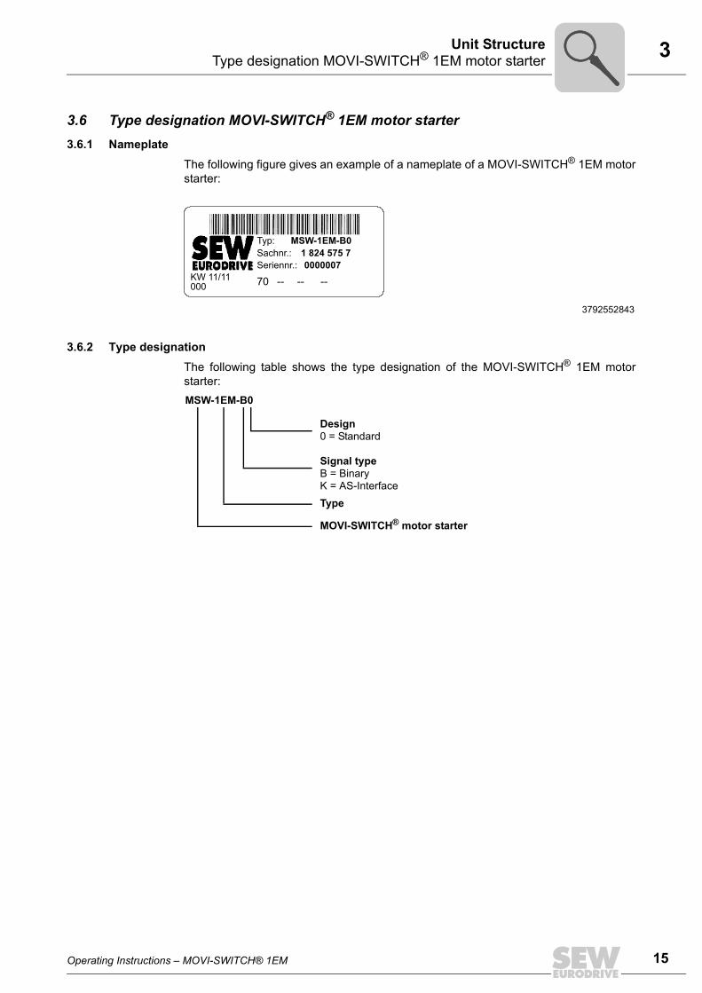
3.6 Type designation MOVI-SWITCH® 1EM motor starter3.6.1 Nameplate
The following figure gives an example of a nameplate of a MOVI-SWITCH® 1EM motorstarter:
3.6.2 Type designationThe following table shows the type designation of the MOVI-SWITCH® 1EM motorstarter:
3792552843
KW 11/11
Typ: MSW-1EM-B0Sachnr.: 1 824 575 7Seriennr.:
70 -- -- --0000007
000
MSW-1EM-B0
Design0 = Standard
Signal typeB = BinaryK = AS-InterfaceType
MOVI-SWITCH® motor starter
Operating Instructions – MOVI-SWITCH® 1EM
15
16
4 eneral informationechanical Installation
4 Mechanical Installation4.1 General information
• Observe the general safety notes.
• Strictly observe all instructions as to the technical data and the permissibleconditions regarding the place of installation.
• Only use the provided attachment options when mounting the MOVI-SWITCH®
drive.
• Only use mounting and locking elements that fit into the existing bores, threads andcountersinks.
4.2 Installation requirementsMake sure that the following requirements are met before you start installing the unit:
• The data on the nameplate of the drive matches the voltage supply system.
• The drive is undamaged (no damage caused by transportation or storage)
• The ambient temperature corresponds to the specifications in chapter "TechnicalData". Note that the temperature range of the gear unit may also be restricted (seegear unit operating instructions).
• The MOVI-SWITCH® drive must not be installed under the following harmful ambientconditions:
– Potentially explosive atmospheres
– Oils
– Acids
– Gases
– Vapors
– Radiation
– etc.
• When the drive is installed in abrasive ambient conditions, protect the output end oilseals against wear.
4.2.1 Installation tolerancesThe following table shows the permitted tolerances of the shaft ends and flanges of theMOVI-SWITCH® drive.
Shaft end FlangesDiameter tolerance according to EN 50347• ISO j6 with Ø ≤ 26 mm• ISO k6 with Ø ≤ 38 mm up to ≤ 48 mm • ISO m6 at Ø > 55 mm• Center bore in accordance with DIN 332,
shape DR..
Centering shoulder tolerance in accordance with EN 50347• ISO j6 with Ø ≤ 250 mm• ISO h6 with Ø > 300 mm
GM
Operating Instructions – MOVI-SWITCH® 1EM

4Mounting the MOVI-SWITCH® driveMechanical Installation
4.3 Mounting the MOVI-SWITCH® drive
Observe the following mounting instructions:
• Install the MOVI-SWITCH® drive only in the specified mounting position on a level,vibration-free, and torsionally rigid support structure.
• Adhere to the mounting position specified on the motor nameplate.
• Thoroughly remove any anti-corrosion agent from the shaft end. Use a commerciallyavailable solvent. Do not allow the solvent to penetrate the bearings and shaft seals– this could damage the material.
• Align the motor carefully to avoid placing any unacceptable strain on the motorshafts. Observe the permitted overhung and axial forces.
• Do not jolt or hammer the shaft end.
• Use an appropriate cover to prevent objects or fluids from entering motors in verticalmounting positions.
• Ensure sufficient clearance around the unit to allow for adequate cooling. Avoid thedrawing in of warm outlet air of other units.
• Balance components that were subsequently mounted to the shaft with a half key(output shafts are balanced with a half key).
• Existing condensation drain holes are sealed with plastic plugs. Only open them, ifnecessary.
• Open condensation drain holes are not permitted. If condensation drain holes areopen, higher degrees of protection are no longer possible.
4.4 Installation in damp locations or in the openObserve the following notes for mounting the MOVI-SWITCH® drive in damp areas orin the open:
• Use suitable cable glands for the cables. Use reducing adapters, if necessary.
• Coat the threads of the cable glands and filler plugs with sealing compound andtighten them properly. Then coat the cable glands again.
• Seal the cable entries properly.
• Before installing the MOVI-SWITCH® motor starter again, clean its sealing surfacesthoroughly.
• If the corrosion protection coating is damaged, restore the coating.
• Check whether the degree of protection specified on the nameplate is permitted inthe ambient conditions on site.
NOTICELoss of warranted degree of protection if the MOVI-SWITCH® motor starter is installedincorrectly or not at all.
Damage to the MOVI-SWITCH® motor starter.• When you remove the MOVI-SWITCH® motor starter from the connection box, you
must protect it from moisture and dust.
Operating Instructions – MOVI-SWITCH® 1EM
17
18
4 ightening torquesechanical Installation
4.5 Tightening torques4.5.1 MOVI-SWITCH® motor starter/connection box
Tighten the screws on the MOVI-SWITCH® motor starter using 3.0 Nm (26 lb.in) workingdiagonally across.
4.5.2 Blanking plug cable glandsTighten screw plugs with 2.5 Nm (22 lb.in).
9007202128496523
9007202128500363
TM
Operating Instructions – MOVI-SWITCH® 1EM

5Installation instructionsElectrical Installation
5 Electrical Installation5.1 Installation instructions5.1.1 Connecting supply system leads
• The rated voltage and frequency of the MOVI-SWITCH® 1EM drive must correspondto the data for the supply system (line).
• Install the fuses at the beginning of the supply system lead behind the supply busjunction. Use only D, D0, NH fuses or circuit breakers. Select the fuse size accordingto the cable cross section.
• Cable cross section: according to input current Iline for rated power (see chapter"Technical Data").
5.1.2 AS-Interface• Connect the required AS-Interface cables (+ sensor cables).
• Route the AS-Interface cables (and sensor cables) separately from power supplycables.
5.1.3 Binary control + DC 24 V• Connect the required control cables (DC 24 V, RUN, OK).
• Route the control cables separately from power supply cables.
5.1.4 Permitted cable cross section of terminalsPower terminals Adhere to the permitted cable cross sections for installation:
Control terminals Observe the permitted cable cross sections for installation:
Power terminals X105 / X106Cable cross section
Conductor without end sleeve 1.0 mm2 – 2.5 mm2 AWG17 – AWG14
Conductor with end sleeve 1.0 mm2 – 1.5 mm2 AWG17 – AWG15
Conductor end sleeves • Only connect single-wire conductors or flexible conductors with conductor end sleeve (DIN 46228, material E-CU) with or without insulating shrouds
• Permitted length of the conductor end sleeve: at least 8 mm
Control terminals X101Cable cross section
0.5 mm2 – 1.0 mm2
AWG20 – AWG17
• Single-wire conductor(bare wire)
• Flexible conductor (bare litz wire)
• Conductor with end sleeve Without insulating shrouds
• Conductor with end sleeve With insulating shrouds
0.5 mm2 – 0.75 mm2
AWG20 – AWG19
Conductor end sleeves • Connect only single-wire conductors or flexible wire conductors with or without conductor end sleeve (DIN 46228, material E-CU).
• Permitted length of the conductor end sleeve: at least 8 mm
Operating Instructions – MOVI-SWITCH® 1EM
19
20
5 stallation instructionslectrical Installation
5.1.5 Power terminals X105 – X106Observe the following information for connecting the power cable to the powerterminals:
Connecting the conductorwithout screwdriver1)
1) Single-wire conductors and flexible conductors with conductor end sleeves can be installed directly(without tool) up to two cross-section sizes below the rated cross-section.
Connecting the conductorwith screwdriver2)
2) You will need to firmly insert a screw driver into the activation opening to open the clamping spring andinstall untreated, flexible conductors or those with a small cross-section that cannot be installed directly.
3791636491 3791609099
2.
1.
InE
Operating Instructions – MOVI-SWITCH® 1EM

5Installation instructionsElectrical Installation
5.1.6 Control terminals X101
Observe the following information for connecting the cables to control terminals X101:21to X101:32:
Before removing the conductor, first press the actuation button on top.
Connecting the conductorwithout pressing the actuation button
Connecting the conductorafter pressing the actuation button
9007199919965835 9007200623153931
Single-wire conductors and flexibleconductors with conductor end sleevescan be installed directly (without tool) upto two cross section sizes below thenominal cross section.
You will need to press the actuationbutton on top to open the clamping springfor installing untreated, flexible conduc-tors or those with a small cross sectionthat cannot be installed directly.
Removing the conductor after pressing the actuation button
9007199735787147
1.
2.
1.2.
Operating Instructions – MOVI-SWITCH® 1EM
21
22
5 stallation instructionslectrical Installation
5.1.7 Notes on PE connection
WARNINGElectric shock due to incorrect connection of PE.
Severe or fatal injuries.• The permitted tightening torque for the screw is 2.0 – 2.4 Nm (18 – 21 lb.in).• Observe the following notes regarding PE connection.
Prohibited assembly Recommendation: Assembly with forked cable lugPermitted for all cross sections
Assembly with solid connecting wirePermitted for cross sections up to max. 2.5 mm2
323042443 323034251 323038347
[1] Forked cable lug suitable for M5 PE screws
[1]
M5
2.5 mm²
M5
InE
Operating Instructions – MOVI-SWITCH® 1EM

5Installation instructionsElectrical Installation
5.1.8 Installation above 1000 m asl
MOVI-SWITCH® 1EM drives with line voltages of 380 to 500 V can be used in altitudesof 1000 m and up to a maximum of 4000 m above sea level under the following condi-tions.1)
• The nominal continuous power is reduced due to the reduced cooling above 1000 m(see chapter "Technical Data").
• Above 2000 m asl, the air and creeping distances are only sufficient for overvoltageclass 2. If the installation calls for overvoltage class 3, you will have to install addi-tional external overvoltage protection to limit overvoltage peaks to 2.5 kV phase-to-phase and phase-to-ground.
• If safe electrical disconnection is required, it must be implemented outside the unitfor altitudes of 2000 m above sea level and higher (safe electrical disconnection inaccordance with EN 61800-5-1).
• At installation altitudes between 2000 m and 4000 m above sea level, the permittednominal line voltage is reduced by 6 V per 100 m.
5.1.9 Protection devicesMOVI-SWITCH®-1EM drives are equipped with integrated protection devices againstmotor overload. External motor protection devices are not necessary.
1) The maximum altitude is limited by creeping distances and flameproof components, such as capacitors.
Operating Instructions – MOVI-SWITCH® 1EM
23
24
5 onnecting MOVI-SWITCH® 1EM with binary controllectrical Installation
5.2 Connecting MOVI-SWITCH® 1EM with binary control5.2.1 Connection MOVI-SWITCH® MSW / AVS1
The following figure shows the connection in MSW / AVS1 design:
The AC 400 V input (L1 – L3) is available as plug connector as an option (page 28).
X01: Binary inputs/outputs
18014401275058571
CW Clockwise rotation CCW Counterclockwise rotation
12
43
X101
X01
OK RUN NC NC NC NC NC NC 24V 0V TF1 TF2
1 2 3 4 5 6 7 8 9 10 11 12
TF
MOVI-SWITCH MSW / AVS1®
WH BN
WH
BU
BN
BK
BU BK
1 2 3
PE
X105 X106
L1in
L1 L2 L3 L1 L2 L3
L2in
L3in
1 2 3
L1out
L2out
L3out
(CW)
(L2 L1 L3) (L2 L1 L3)(CCW)
FunctionBinary inputs/outputs
Connection typeM12, 4-pole, male, A-coded
Wiring diagram
2718233355
AssignmentNo. Name Function1 +24 V Power supply voltage DC 24 V
2 RUN Control signal DC 24 V0: Stop drive1: Start drive
3 0V24 Reference potential 0V24
4 OK Feedback ready, DC 24 V0: Overtemperature or no DC 24 V supply1: Ready
2 1
43
CE
Operating Instructions – MOVI-SWITCH® 1EM

5Connecting MOVI-SWITCH® 1EM with AS-InterfaceElectrical Installation
5.3 Connecting MOVI-SWITCH® 1EM with AS-Interface5.3.1 Connecting MOVI-SWITCH® MSW / AVSK
The following figure shows the connection in MSW / AVSK design:
The AC 400 V input (L1 – L3) is available as plug connector as an option (page 28).
X01: AS-Interface The following table informs about this connection:
18014401261959819
12
43
X101
X01
DI3 DI2 DO1 0V 0V 0V 24V 24V AS+ AS- TF1 TF2
1 2 3 4 5 6 7 8 9 10 11 12
TF
MOVI-SWITCH MSW / AVSK®
WH
WH
BK
BK
1 2 3
PE
X105 X106
L1in
L1 L2 L3 L1 L2 L3
L2in
L3in
1 2 3
L1out
L2out
L3out
(CW)
(L2 L1 L3) (L2 L1 L3)(CCW)
FunctionConnection of AS-Interface data cable
Connection typeM12, 4-pole, male, A-coded
Wiring diagram
2718233355
AssignmentNo. Name Function1 AS+ AS-Interface data cable (+)
2 n.c. Not connected
3 AS− AS-Interface data cable (−)
4 n.c. Not connected
2 1
43
Operating Instructions – MOVI-SWITCH® 1EM
25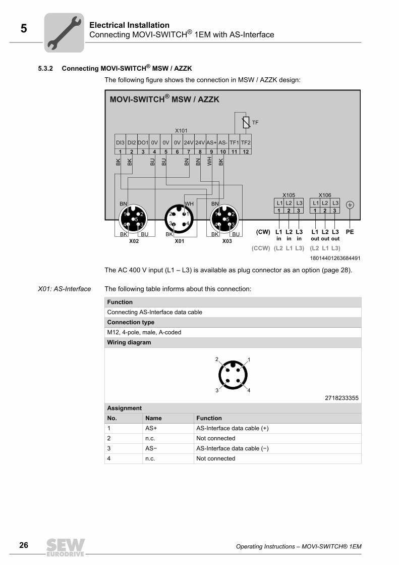
26
5 onnecting MOVI-SWITCH® 1EM with AS-Interfacelectrical Installation
5.3.2 Connecting MOVI-SWITCH® MSW / AZZKThe following figure shows the connection in MSW / AZZK design:
The AC 400 V input (L1 – L3) is available as plug connector as an option (page 28).
X01: AS-Interface The following table informs about this connection:
18014401263684491
1
4 3
25
1
4 3
25
12
43
X101
X01X02 X03
DI3 DI2 DO1 0V 0V 0V 24V 24V AS+ AS- TF1 TF2
1 2 3 4 5 6 7 8 9 10 11 12
TF
MOVI-SWITCH MSW / AZZK®
WH BNBNW
H
BN
BN
BU
BU
BK
BK
BK
BK BUBKBK BU
1 2 3
PE
X105 X106
L1in
L1 L2 L3 L1 L2 L3
L2in
L3in
1 2 3
L1out
L2out
L3out
(CW)
(L2 L1 L3) (L2 L1 L3)(CCW)
FunctionConnecting AS-Interface data cable
Connection typeM12, 4-pole, male, A-coded
Wiring diagram
2718233355
AssignmentNo. Name Function1 AS+ AS-Interface data cable (+)
2 n.c. Not connected
3 AS− AS-Interface data cable (−)
4 n.c. Not connected
2 1
43
CE
Operating Instructions – MOVI-SWITCH® 1EM

5Connecting MOVI-SWITCH® 1EM with AS-InterfaceElectrical Installation
X02: DI2 sensor input
The following table informs about this connection:
X03: DI3 sensor input
The following table informs about this connection:
FunctionDI2 sensor input
Connection typeM12, 5-pole, female, A-coded
Wiring diagram
2264816267
AssignmentNo. Name Function1 +24 V DC 24 V voltage supply for sensors
2 N.C. Not connected
3 0V24 0 V reference potential for sensors
4 DI2 DI2 sensor input
5 N.C. Not connected
1
4 3
2
5
FunctionDI3 sensor input
Connection typeM12, 5-pole, female, A-coded
Wiring diagram
2264816267
AssignmentNo. Name Function1 +24 V DC 24 V voltage supply for sensors
2 N.C. Not connected
3 0V24 0 V reference potential for sensors
4 DI3 DI3 sensor input
5 N.C. Not connected
1
4 3
2
5
Operating Instructions – MOVI-SWITCH® 1EM
27
28
5 ND3 option (power plug connector)lectrical Installation
5.4 KND3 option (power plug connector)
5.4.1 X00: AC 400 V inputThe following table informs about this connection:
The MSW / ... / KND3 option is equippedwith an X00 plug connector for connectingthe 400 V supply.
9007202434937483
1 2 3
X105 X106L1 L2 L3 L1 L2 L3
1 2 3
L1out
L2out
L3out8 2 6
123
4
5
678
X00
GNYE
MSW / ... / KND3
FunctionAC 400 V input
Connection typeQ 8/0, male
Wiring diagram
2780745355
AssignmentNo. Name Function1 n.c. Not connected
2 L2 Supply system phase 2
3 n.c. Not connected
4 n.c. Not connected
5 n.c. Not connected
6 L3 Supply system phase 3
7 n.c. Not connected
8 L1 Supply system phase 1
PE PE Equipotential bonding/protective earth conductor
1
PE
4
7
6
3
5
8
2
KE
Operating Instructions – MOVI-SWITCH® 1EM

6Important notes on startupStartup
6 Startup6.1 Important notes on startup
Before startup, make sure that:• The drive is undamaged and not blocked
• All connections have been established correctly
• The direction of rotation of the motor/gearmotor is correct
• All protective covers have been installed correctly
During startup, make sure that:• The motor is running properly (no speed fluctuations, no loud noises, etc.).
On brake motors with a self-reengaging manual brake release, the hand lever must beremoved after startup! A bracket is provided for storing the lever on the outside of themotor.
6.1.1 Monitoring• The MOVI-SWITCH®1EM motor starter monitors the power semiconductors of the
motor starter and the motor winding for overtermperature.
• In the event of overtemperature, the MOVI-SWITCH® 1EM drive switches offautomatically.
• The output signal / AS-Interface bit "OK" indicates the monitoring status.
The output signal / AS-Interface bit "OK" must be evaluated by a higher-levelcontroller.
CAUTION Risk of crushing due to unexpected start of the drive. If the drive wasswitched-off due to overtemperature, it will automatically start up once it has cooleddown.
Severe or fatal injuries.
– If automatic restarting could pose a risk to persons or components, you mustimplement an external restart lock.
• The MOVI-SWITCH® 1EM motor starter is protected against supply system over-voltage.
6.2 RequirementsThe following conditions apply to startup:• The MOVI-SWITCH® drive must be installed correctly both mechanically and electri-
cally.
• Appropriate safety measures prevent the drives from starting up unintentionally.
• Appropriate safety measures must be taken to prevent risk of injury or damage tomachine.
Operating Instructions – MOVI-SWITCH® 1EM
00
I
29

30
6 tartup MOVI-SWICH® 1EM with binary controltartup
6.3 Startup MOVI-SWICH® 1EM with binary control6.3.1 Starting the drive
1. Check the connection of the MOVI-SWITCH® 1EM drive.
See chapter "Electrical Installation".
2. Switch on the line voltage.
3. Switch on the MOVI-SWITCH® 1EM drive with the control signal "RUN" = "1".
6.4 Starting up MOVI-SWICH® 1EM with AS-Interface6.4.1 Starting the drive
1. Check the connection of the MOVI-SWITCH® 1EM drive.
See chapter "Electrical Installation".
2. Take the AS-Interface master into operation.
3. Set the AS-Interface address of MOVI-SWITCH® 1EM.
See chapter "Assigning the AS-Interface address" (page 31).
4. Switch on the line voltage.
5. Set the AS-Interface bit DO2 for supplying the module electronics to "1".
6. Switch on the MOVI-SWITCH® 1EM drive with the AS-Interface bit DO0 (RUN) = "1".
6.4.2 Data transmission AS-Interface master → MOVI-SWITCH® 1EMThe following table shows the 3 data bits that the AS-Interface master sends to MOVI-SWITCH® 1EM:
Bit Function
DO0RUN0: Drive stops.1: Drive starts.
DO1 Output DO1, external actuator
DO2Module electronics0: Module electronics is not supplied.1: Module electronics is supplied with DC 24 V by the AS-Interface cable.
SS
00
I
Operating Instructions – MOVI-SWITCH® 1EM

6Starting up MOVI-SWICH® 1EM with AS-InterfaceStartup
6.4.3 Data transmission MOVI-SWITCH® 1EM → AS-Interface master
The following table shows the 4 data bits that MOVI-SWITCH® 1EM sends back to theAS-Interface master via the AS-Interface:
6.4.4 Assigning the AS-Interface slave addressSEW-EURODRIVE supplies MOVI-SWITCH® 1EM with AS-Interface with address 0.
You have the following options for assigning the AS-Interface address of MOVI-SWITCH® 1EM (addresses 1A – 31A, 1B – 31B):
• Addresses are assigned automatically within a configured AS-Interface systemwhen replacing a MOVI-SWITCH® 1EM drive.
The following prerequisites must be fulfilled:
– The new MOVI-SWITCH® 1EM drive must have address 0.
– If you need to replace several MOVI-SWITCH® 1EM drives, you must exchangethem individually (one after another).
• Manual address assignment via the plant masterConnect the drives to the AS-Interface cable one after another. Doing so preventsseveral MOVI-SWITCH® 1EM drives from being assigned the same AS-Interfaceaddress.
• Manual address assignment using a hand-held AS-Interface programmingdevice.Observe the notes in the following chapter when connecting the MOVI-SWITCH®
1EM drive to the AS-Interface cable.
Bit Function
DI0OK (ready signal)0: MOVI-SWITCH® 1EM is not ready.1: MOVI-SWITCH® 1EM is ready.
DI1 No function
DI2Sensor input 10: The signal of sensor 1 = "0"1: The signal of sensor 1 = "1"
DI3Sensor input 20: The signal of sensor 2 = "0"1: The signal of sensor 2 = "1"
Operating Instructions – MOVI-SWITCH® 1EM
00
I
31

32
6 tarting up MOVI-SWICH® 1EM with AS-Interfacetartup
Assigning the slave address using a hand-held programming device
Hand-held AS-Interface programming devices offer the following functions:
• Reading out and changing an AS-Interface slave address
• Reading out the AS-Interface profile
• Reading out and changing data bits
• Function check and test run.
When using a hand-held programming device, you need a connection cable that fits ontothe AS-Interface plug connector X01 of MOVI-SWITCH®-1EM (see the following figure).
Example:
1. Disconnect the AS-Interface nodes from the AS-Interface network one at a time andassign addresses via the hand-held programming device (A).
2. Then reconnect the respective AS-Interface node to the AS-Interface network (B).
2384154763
1: AS-Interface +2. n. c.3: AS-Interface −4: n. c.
2873767051
[1] AS-Interface hand-held programming device
2 1
43
A B
[1]
SS
00
I
Operating Instructions – MOVI-SWITCH® 1EM

7Operating display of MOVI-SWITCH® 1EM with binary controOperation
7 Operation7.1 Operating display of MOVI-SWITCH® 1EM with binary control
The following figure shows the position of the status LED on the MOVI-SWITCH® 1EMmotor starter:
7.1.1 Meaning of the status LEDThe three-color status LED indicates the operating and error states of the MOVI-SWITCH® 1EM drive.
9007202128506123
[1] Status LED
[1] STATUSM
OVI
-SW
ITC
H®
Status LEDColor Status Operating state Description– Off Not ready No DC 24 V supply
Yellow Illumi-nated
Ready DC 24 V supply OK
Green Illumi-nated
Enable "RUN" signal is present
Red Illumi-nated
Overtemperature error
Temperature monitoring of the motor and/or the power semiconductor has tripped due to ove-rtemperature and has stopped the drive.The drive starts up automatically once it has cooled down, see chapter "Monitoring" (page 29).
Operating Instructions – MOVI-SWITCH® 1EM
l
33

34
7 perating display of MOVI-SWITCH® 1EM with AS-Interfaceperation
7.2 Operating display of MOVI-SWITCH® 1EM with AS-InterfaceThe following figure shows the position of the status LED on the MOVI-SWITCH® 1EMmotor starter:
7.2.1 Meaning of the status LEDThe three-color status LED indicates the operating and error states of the MOVI-SWITCH® 1EM drive.
3842369803
[1] Status LED
[1] STATUS
MO
VI-S
WIT
CH
®
Status LEDColor Status Operating state Description– Off Not ready No connection to AS-Interface
Green Illumi-nated
Ready for operation
Normal operation (communication established)
Red Illumi-nated
AS-Interface communication error
AS-Interface communication interrupted
Slave address set to 0
Slave address not configured in the AS-Interface master. Master in protected operating mode.
Red / green
Flashing Overtemperature error
Temperature monitoring of the motor and/or the power semiconductor has tripped due to over-temperature and has stopped the drive.The drive starts up automatically once it has cooled down, see chapter "Monitoring" (page 29).
OO
Operating Instructions – MOVI-SWITCH® 1EM

8Diagnosing MOVI-SWITCH® 1EM with binary controService
8 Service8.1 Diagnosing MOVI-SWITCH® 1EM with binary control
The following table helps you with troubleshooting:
8.2 Diagnosing MOVI-SWITCH® 1EM with AS-InterfaceThe following table helps you with troubleshooting:
Problem Possible cause SolutionDrive turns in the wrong direction
Incorrect phase sequence
• Swap 2 phases on the input power terminals X105 and X106
Motor does not run, no current con-sumption
Missing line voltage • Check incoming cable, correct• Check line protection fuse, replace
No DC 24 V supply • Check DC 24 V supply, connect.Missing "RUN" signal • Set "RUN" signal (pin X101:22 = 24 V).Overtemperature error • Motor or power semiconductor too hot, let it
cool down, reduce load• TF not connected, check connections,
correctMotor buzzes, high current consump-tion
Mechanical compo-nents blocking Defective winding
• Correct mechanical fault• Replace drive
2-phase operation • Check fuses and line cable connections• Provide 3 phases
Brake does not release • Carry out brake maintenance, see operating instructions of the motor
Brake rectifier is defect • Replace brake rectifier
Problem Possible cause SolutionDrive turns in the wrong direction
Incorrect phase sequence
• Swap 2 line phases on the motor terminals
Motor does not run, no current con-sumption
Missing line voltage • Check incoming cable, correct• Check line protection fuse, replace
Missing power supply for module electronics
• Set AS-Interface signal (bit DO2) = "1"
Missing "RUN" signal • Set "RUN" signal (bit DO0) = "1"Overtemperature error • Motor or power semiconductor too hot, let it
cool down, reduce load• TF not connected, check connections,
correctNo communication • Check AS-interface master programming
• Change address modeMotor buzzes, high current consump-tion
Mechanical compo-nents blocking Defective winding
• Correct mechanical fault• Replace drive
2-phase operation • Check fuses and line cable connections• Provide 3 phases
Brake does not release • Carry out brake maintenance, see operating instructions of the motor
Brake rectifier is defect • Replace brake rectifier
Operating Instructions – MOVI-SWITCH® 1EM
l
35

36
8 EW Serviceervice
8.3 SEW ServiceIf a fault cannot be remedied, please contact SEW Service (see "Address List").
Please have the following information at hand when you consult the SEW Service:
• Type designation on the electronics nameplate [1]
• Part number [2]
• Serial number [3]
• Service code [4]
• Type designation on the motor nameplate [5]
• Brief description of the application (application, binary control or AS-Interface)
• Nature of the fault
• Accompanying circumstances (e.g. initial startup)
• Your own assumptions
• Any unusual events preceding the problem, etc.
3792071691
KW 11/11
Typ: MSW-1EM-B0Sachnr.: 1 824 575 7Seriennr.:
70 -- -- --0000007
000
W10DT56M4/BMG/TF/MSW/AZZK/KND3
0.09/S1400
1300/47 230 1.2
5.3 12BG1.2
M3B0.68
0,31 54
27,50
F
[1][2][3][4]
[5]
SS
Operating Instructions – MOVI-SWITCH® 1EM

8Inspection/maintenanceService
8.4 Inspection/maintenance8.4.1 MOVI-SWITCH® 1EM motor starter
The MOVI-SWITCH® 1EM motor starter is maintenance free. SEW-EURODRIVE doesnot prescribe any inspection or maintenance work for the motor starter.
8.4.2 MotorThe motor requires regular inspection and maintenance work.
Observe the notes and instructions in chapter "Inspection/Maintenance" of the motoroperating instructions.
8.4.3 Gear unit (only for gearmotors)The gear unit requires regular inspection and maintenance work.
Observe the notes and instructions in chapter "Inspection/Maintenance" of the gear unitoperating instructions.
8.5 ShutdownTo shut down the MOVI-SWITCH® drive, de-energize it using appropriate measures.
8.6 StorageObserve the following instructions when shutting down or storing the MOVI-SWITCH®
drive:
• If you shut down and store the MOVI-SWITCH® drive for a longer period, you mustclose open cable entries and cover contacts with protective caps.
• Make sure that the unit is not subject to mechanical impact during storage.
Observe the notes on storage temperature in the "Technical Data" chapter.
8.7 DisposalThis product consists of:• Iron
• Aluminum
• Copper
• Plastic
• Electronic components
Dispose of all components in accordance with applicable regulations!
Operating Instructions – MOVI-SWITCH® 1EM
37
38
9 E marking and C-Tickechnical Data
9 Technical Data9.1 CE marking and C-Tick9.1.1 CE marking
• Low voltage directive:
MOVI-SWITCH® 1EM drives meet the requirements stipulated in the low voltagedirective 2006/95/EC.
• Electromagnetic compatibility (EMC):
The designated use of MOVI-SWITCH® 1EM drives is as components for installationin machinery and systems. Provided that you comply with the installation instruc-tions, the CE marking requirements for the entire machine/system in which they areinstalled are satisfied on the basis of the EMC directive 2004/108/EC. For detailedinformation on EMC compliant installation, refer to the publication "ElectromagneticCompatibility in Drive Engineering" from SEW-EURODRIVE.
The CE mark on the nameplate indicates conformity with the Low Voltage Directive2006/95/EC and the EMC Directive 2004/108/EC.
9.1.2 C-TickC-Tick approval for the MOVI-SWITCH®-1EM unit series is in preparation.
C-Tick certifies conformity with ACA (Australian Communications Authority) standards.
CT
Pi
fkVA
Hz
n
Operating Instructions – MOVI-SWITCH® 1EM

9Technical data of MOVI-SWITCH® 1EM with binary controTechnical Data
9.2 Technical data of MOVI-SWITCH® 1EM with binary control
MOVI-SWITCH® 1EM type ... MSW-1EM-B0 / AVS1
MSW module electronics MSW-1EM-B0
Part number of MSW module electronics
1 824 575 7
Line voltages(depending on the motor)
Vline AC 3 x 380 V / 400 V / 415 V / 460 V / 480 V / 500 V ± 10%
Line frequency(depending on the motor)
fline 50 – 60 Hz ± 10%
Rated operating current AC 1.0 A (at 400 V)AC 0.75 A (at 500 V)
Position of normal use Any
Motor protection TF
Maximum starting frequency
600 cycles/h
Cycle times Typical switch-on/switch-off time: 10 ms
Interference immunity Meets EN 61800-3
Interference emission Complies with EN 61800-3 and class A limit to EN 55011 and EN 55014
Ambient temperature ϑA -20 – +40 ˚C (PN reduction: 3% Irated per K up to max. 60 °C), no moisture condensation
Storage temperature ϑL -25 – +85 °C (EN 60721-3-3, class 3K3)
Climate class EN 60721-3-3, class 3K3
Pollution class 2 according to IEC 60664-1 (VDE 0110-1)
Degree of protection IP54, IP55, IP65 (optional, specify when ordering)
Duty type S1 (EN 60149-1-1 and 1-3), S3 max. cycle duration 10 minutes
Type of cooling (DIN 41 751)
Self-cooling
Installation altitude h ≤ 1000 m: no reduction of performanceh > 1000 m: Prated reduction by 1% per 100 mh > 2000 m: Vline reduction by AC 6 V per 100 m to max. 3 x 400 V at 4000 m aslhmax = 4000 m(see also chapter "Electrical Installation – Installation instructions")
Electronics power supply(M12 connector AVS1)
Pin 1 (24V)Pin 3 (0 V)
U = +24 V ± 25%, EN 61131-2, residual ripple max. 13%IE ≤ 50 mA (without IOK)
Binary inputs Isolated via optocoupler; PLC compatible (EN 61131-2)Ri ≈ 3.0 kΩ, IE ≈ 10 mA, sampling cycle ≤ 5 ms
Signal level DC 13 – 30 V = "1" = contact closedDC −3 – +5 V = "0" = contact open
Control functions (M12 connector AVS1)
Pin 2 RUN/stop
"OK" output(M12 connector AVS1)
Pin 4 Response time ≤ 10 ms
Signaling function(M12 connector AVS1)
Pin 4 Output for ready signal
Ready for operation checkback signal (high): VOK > V24 V -3 V- with voltage present (24 V + supply system)- in case no error was detected- at end of self-testing phase (when unit is turned on)
IOK Current for checkback max. 0.65 A, short-circuit proof
Operating Instructions – MOVI-SWITCH® 1EM
lP
if
kVA
Hz
n
39

40
9 echnical data of MOVI-SWITCH® 1EM with AS-Interfaceechnical Data
9.3 Technical data of MOVI-SWITCH® 1EM with AS-Interface
MOVI-SWITCH® 1EM type ... MSW-1EM-K0 / AVSK ... MSW-1EM-K0 / AZZK
MSW module electronics MSW-1EM-K0
Part number of MSW module electronics
1 270 312 5
Line voltages(depending on the motor)
Vline AC 3 x 380 V / 400 V / 415 V / 460 V / 480 V / 500 V ± 10%
Line frequency(depending on the motor)
fline 50 – 60 Hz ± 10%
Rated operating current AC 1.0 A (at 400 V)AC 0.75 A (at 500 V)
Position of normal use Any
Motor protection TF
Maximum starting frequency
600 cycles/h
Cycle times Typical switch-on/switch-off time: 10 ms
Interference immunity Meets EN 61800-3
Interference emission Complies with EN 61800-3 and class A limit to EN 55011 and EN 55014
Ambient temperature ϑA -20 – +40 ˚C (PN reduction: 3% Irated per K up to max. 60 °C), no moisture condensation
Storage temperature ϑL -25 – +85 °C (EN 60721-3-3, class 3K3)
Climate class EN 60721-3-3, class 3K3
Pollution class 2 according to IEC 60664-1 (VDE 0110-1)
Degree of protection IP54, IP55, IP65 (optional, specify when ordering)
Duty type S1 (EN 60149-1-1 and 1-3), S3 max. cycle duration 10 minutes
Type of cooling (DIN 41 751)
Self-cooling
Installation altitude h ≤ 1000 m: no reduction of performanceh > 1000 m: Prated reduction by 1% per 100 mh > 2000 m: Vline reduction by AC 6 V per 100 m to max. 3 x 400 V at 4000 m aslhmax = 4000 m (see also chapter "Electrical Installation - Installation instructions")
AS-Interface ASI+ASI-
Vin AS-Interface = +29.5 – +31.6 V (AS-Interface power supply unit according to EN 50295)I ≤ 100 mA including sensor supply(typically 25 mA at 30 V without sensor supply)
Protocol variant AS-Interface binary slave with S-7-A.E profile "4I/3O AB slave"
AS-Interface profile S-7.A.E
I/O configuration 7hex
ID code Ahex
ext. ID code 2 Ehex
ext. ID code1 7hex
Address 1A – 31A and 1B – 31B (AB slave, address factory set to 0)
Watchdog ≥ 40 ms (all outputs de-energized)
Sensor connections
Voltage supply + 24V0V
Vout sensor ≥ Uin AS-Interface - 7 VIout sensor max = 75 mA, short-circuit proof
Sensor inputs PLC-compatible in accordance with EN 61131-2Ri about 3.0 kΩ IE about 10 mA
Signal level +15 V – +30 V –3 V – +5 V
"1""0"
Maximum sensor cable length
15 m
TT
Pi
fkVA
Hz
n
Operating Instructions – MOVI-SWITCH® 1EM

10Declaration of Conformity
10 Declaration of Conformity
2780051467
EC Declaration of Conformity
BruchsalJohann Soder
Place Date Managing Director Technology a) b)
a) Authorized representative for issuing this declaration on behalf of the manufacturer b) Authorized representative for compiling the technical documents
900330110
01.09.10
SEW-EURODRIVE GmbH & Co KGErnst-Blickle-Straße 42, D-76646 Bruchsaldeclares under sole responsibility that the following products
electronic motor starters of the series MOVI-SWITCH®
possibly in connection with AC motor
are in conformity with
Low Voltage Directive 2006/95/EC
EMC Directive 2004/108/EC 4)
Applied harmonized standards EN 50178:1997EN 60034-1:2004EN 60664-1:2008EN 61800-3:2007
4) According to the EMC Directive, the listed products are not independently operable products. EMCassessment is only possible after these products have been integrated in an overall system. Theassessment was verified for a typical system constellation, but not for the individual product.
Operating Instructions – MOVI-SWITCH® 1EM
41
42
11 ddress List
11 Address List
Germany
HeadquartersProductionSales
Bruchsal SEW-EURODRIVE GmbH & Co KGErnst-Blickle-Straße 42 D-76646 BruchsalP.O. BoxPostfach 3023 • D-76642 Bruchsal
Tel. +49 7251 75-0Fax +49 7251 75-1970http://[email protected]
Production / Indus-trial Gears
Bruchsal SEW-EURODRIVE GmbH & Co KGChristian-Pähr-Str.10D-76646 Bruchsal
Tel. +49 7251 75-0Fax +49 7251 75-2970
Service Compe-tence Center
Central SEW-EURODRIVE GmbH & Co KGErnst-Blickle-Straße 1 D-76676 Graben-Neudorf
Tel. +49 7251 75-1710Fax +49 7251 [email protected]
North SEW-EURODRIVE GmbH & Co KGAlte Ricklinger Straße 40-42 D-30823 Garbsen (near Hannover)
Tel. +49 5137 8798-30Fax +49 5137 [email protected]
East SEW-EURODRIVE GmbH & Co KGDänkritzer Weg 1D-08393 Meerane (near Zwickau)
Tel. +49 3764 7606-0Fax +49 3764 [email protected]
South SEW-EURODRIVE GmbH & Co KGDomagkstraße 5D-85551 Kirchheim (near München)
Tel. +49 89 909552-10Fax +49 89 [email protected]
West SEW-EURODRIVE GmbH & Co KGSiemensstraße 1D-40764 Langenfeld (near Düsseldorf)
Tel. +49 2173 8507-30Fax +49 2173 [email protected]
Electronics SEW-EURODRIVE GmbH & Co KGErnst-Blickle-Straße 42 D-76646 Bruchsal
Tel. +49 7251 75-1780Fax +49 7251 [email protected]
Drive Service Hotline / 24 Hour Service +49 180 5 SEWHELP+49 180 5 739435714 euro cents/min on the German land-line network. Max 42 euro cents/min from a German mobile network. Prices for mobile and international calls may differ.
Additional addresses for service in Germany provided on request!
France
ProductionSalesService
Haguenau SEW-USOCOME 48-54 route de Soufflenheim B. P. 20185F-67506 Haguenau Cedex
Tel. +33 3 88 73 67 00 Fax +33 3 88 73 66 00http://[email protected]
Production Forbach SEW-USOCOME Zone industrielle Technopôle Forbach SudB. P. 30269F-57604 Forbach Cedex
Tel. +33 3 87 29 38 00
AssemblySalesService
Bordeaux SEW-USOCOME Parc d'activités de Magellan62 avenue de Magellan - B. P. 182F-33607 Pessac Cedex
Tel. +33 5 57 26 39 00Fax +33 5 57 26 39 09
Lyon SEW-USOCOME Parc d'affaires RooseveltRue Jacques TatiF-69120 Vaulx en Velin
Tel. +33 4 72 15 37 00Fax +33 4 72 15 37 15
A
Operating Instructions – MOVI-SWITCH® 1EM

11Address List
Nantes SEW-USOCOME Parc d’activités de la forêt4 rue des FontenellesF-44140 Le Bignon
Tel. +33 2 40 78 42 00Fax +33 2 40 78 42 20
Paris SEW-USOCOME Zone industrielle 2 rue Denis Papin F-77390 Verneuil I'Etang
Tel. +33 1 64 42 40 80Fax +33 1 64 42 40 88
Additional addresses for service in France provided on request!
Algeria
Sales Algiers REDUCOM Sarl 16, rue des Frères ZaghnouneBellevue16200 El Harrach Alger
Tel. +213 21 8214-91Fax +213 21 [email protected]://www.reducom-dz.com
Argentina
AssemblySales
Buenos Aires SEW EURODRIVE ARGENTINA S.A.Centro Industrial Garin, Lote 35Ruta Panamericana Km 37,51619 Garin
Tel. +54 3327 4572-84Fax +54 3327 [email protected]://www.sew-eurodrive.com.ar
Australia
AssemblySalesService
Melbourne SEW-EURODRIVE PTY. LTD.27 Beverage DriveTullamarine, Victoria 3043
Tel. +61 3 9933-1000Fax +61 3 9933-1003http://[email protected]
Sydney SEW-EURODRIVE PTY. LTD.9, Sleigh Place, Wetherill Park New South Wales, 2164
Tel. +61 2 9725-9900Fax +61 2 [email protected]
Austria
AssemblySalesService
Wien SEW-EURODRIVE Ges.m.b.H. Richard-Strauss-Strasse 24A-1230 Wien
Tel. +43 1 617 55 00-0Fax +43 1 617 55 00-30http://[email protected]
Belarus
Sales Minsk SEW-EURODRIVE BYRybalkoStr. 26BY-220033 Minsk
Tel.+375 17 298 47 56 / 298 47 58Fax +375 17 298 47 54http://[email protected]
Belgium
AssemblySalesService
Brussels SEW-EURODRIVE n.v./s.a.Researchpark Haasrode 1060Evenementenlaan 7BE-3001 Leuven
Tel. +32 16 386-311Fax +32 16 386-336http://[email protected]
Service Compe-tence Center
Industrial Gears SEW-EURODRIVE n.v./s.a.Rue de Parc Industriel, 31BE-6900 Marche-en-Famenne
Tel. +32 84 219-878Fax +32 84 219-879http://[email protected]
Brazil
ProductionSalesService
São Paulo SEW-EURODRIVE Brasil Ltda.Avenida Amâncio Gaiolli, 152 - Rodovia Presi-dente Dutra Km 208Guarulhos - 07251-250 - SPSAT - SEW ATENDE - 0800 7700496
Tel. +55 11 2489-9133Fax +55 11 2480-3328http://[email protected]
France
Operating Instructions – MOVI-SWITCH® 1EM
43
44
11 ddress List
Bulgaria
Sales Sofia BEVER-DRIVE GmbHBogdanovetz Str.1BG-1606 Sofia
Tel. +359 2 9151160Fax +359 2 [email protected]
Cameroon
Sales Douala Electro-ServicesRue Drouot AkwaB.P. 2024Douala
Tel. +237 33 431137Fax +237 33 [email protected]
Canada
AssemblySalesService
Toronto SEW-EURODRIVE CO. OF CANADA LTD. 210 Walker Drive Bramalea, ON L6T 3W1
Tel. +1 905 791-1553Fax +1 905 791-2999http://[email protected]
Vancouver SEW-EURODRIVE CO. OF CANADA LTD.Tilbury Industrial Park7188 Honeyman Street Delta, BC V4G 1G1
Tel. +1 604 946-5535Fax +1 604 [email protected]
Montreal SEW-EURODRIVE CO. OF CANADA LTD.2555 Rue Leger Lasalle, PQ H8N 2V9
Tel. +1 514 367-1124Fax +1 514 [email protected]
Additional addresses for service in Canada provided on request!
Chile
AssemblySalesService
Santiago SEW-EURODRIVE CHILE LTDA.Las Encinas 1295Parque Industrial Valle GrandeLAMPARCH-Santiago de ChileP.O. BoxCasilla 23 Correo Quilicura - Santiago - Chile
Tel. +56 2 75770-00Fax +56 2 75770-01http://[email protected]
China
ProductionAssemblySalesService
Tianjin SEW-EURODRIVE (Tianjin) Co., Ltd.No. 46, 7th Avenue, TEDATianjin 300457
Tel. +86 22 25322612Fax +86 22 [email protected]://www.sew-eurodrive.com.cn
AssemblySalesService
Suzhou SEW-EURODRIVE (Suzhou) Co., Ltd.333, Suhong Middle RoadSuzhou Industrial ParkJiangsu Province, 215021
Tel. +86 512 62581781Fax +86 512 [email protected]
Guangzhou SEW-EURODRIVE (Guangzhou) Co., Ltd.No. 9, JunDa RoadEast Section of GETDDGuangzhou 510530
Tel. +86 20 82267890Fax +86 20 [email protected]
Shenyang SEW-EURODRIVE (Shenyang) Co., Ltd.10A-2, 6th RoadShenyang Economic Technological Develop-ment AreaShenyang, 110141
Tel. +86 24 25382538Fax +86 24 [email protected]
Wuhan SEW-EURODRIVE (Wuhan) Co., Ltd.10A-2, 6th RoadNo. 59, the 4th Quanli Road, WEDA430056 Wuhan
Tel. +86 27 84478388Fax +86 27 [email protected]
A
Operating Instructions – MOVI-SWITCH® 1EM

11Address List
Xi'An SEW-EURODRIVE (Xi'An) Co., Ltd.No. 12 Jinye 2nd RoadXi'An High-Technology Industrial Development ZoneXi'An 710065
Tel. +86 29 68686262Fax +86 29 [email protected]
Additional addresses for service in China provided on request!
Colombia
AssemblySalesService
Bogotá SEW-EURODRIVE COLOMBIA LTDA. Calle 22 No. 132-60Bodega 6, Manzana BSantafé de Bogotá
Tel. +57 1 54750-50Fax +57 1 54750-44http://[email protected]
Croatia
SalesService
Zagreb KOMPEKS d. o. o.Zeleni dol 10HR 10 000 Zagreb
Tel. +385 1 4613-158Fax +385 1 [email protected]
Czech Republic
Sales Prague SEW-EURODRIVE CZ S.R.O.Lužná 591CZ-16000 Praha 6 - Vokovice
Tel. +420 255 709 601Fax +420 220 121 237http://[email protected]
Drive Service Hotline / 24 Hour Service
HOT-LINE +420 800 739 739 (800 SEW SEW) Servis:Tel. +420 255 709 632Fax +420 235 358 [email protected]
Denmark
AssemblySalesService
Copenhagen SEW-EURODRIVEA/SGeminivej 28-30DK-2670 Greve
Tel. +45 43 9585-00Fax +45 43 9585-09http://[email protected]
Egypt
SalesService
Cairo Copam Egypt for Engineering & Agencies33 EI Hegaz ST, Heliopolis, Cairo
Tel. +20 2 22566-299 +1 23143088Fax +20 2 22594-757http://www.copam-egypt.com/ [email protected]
Estonia
Sales Tallin ALAS-KUUL ASReti tee 4EE-75301 Peetri küla, Rae vald, Harjumaa
Tel. +372 6593230Fax +372 [email protected]
Finland
AssemblySalesService
Lahti SEW-EURODRIVE OYVesimäentie 4FIN-15860 Hollola 2
Tel. +358 201 589-300Fax +358 3 780-6211http://[email protected]
ProductionAssembly
Karkkila SEW Industrial Gears OyValurinkatu 6, PL 8FI-03600 Karkkila, 03601 Karkkila
Tel. +358 201 589-300Fax +358 201 [email protected]://www.sew-eurodrive.fi
China
Operating Instructions – MOVI-SWITCH® 1EM
45
46
11 ddress List
Gabon
Sales Libreville ESG Electro Services GabunFeu Rouge Lalala1889 LibrevilleGabun
Tel. +241 741059Fax +241 [email protected]
Great Britain
AssemblySalesService
Normanton SEW-EURODRIVE Ltd.Beckbridge Industrial Estate NormantonWest Yorkshire WF6 1QR
Tel. +44 1924 893-855Fax +44 1924 893-702http://[email protected]
Drive Service Hotline / 24 Hour Service Tel. 01924 896911
Greece
Sales Athens Christ. Boznos & Son S.A.12, K. Mavromichali StreetP.O. Box 80136GR-18545 Piraeus
Tel. +30 2 1042 251-34 Fax +30 2 1042 251-59http://[email protected]
Hong Kong
AssemblySalesService
Hong Kong SEW-EURODRIVE LTD.Unit No. 801-806, 8th FloorHong Leong Industrial ComplexNo. 4, Wang Kwong Road Kowloon, Hong Kong
Tel. +852 36902200Fax +852 [email protected]
Hungary
SalesService
Budapest SEW-EURODRIVE Kft.H-1037 BudapestKunigunda u. 18
Tel. +36 1 437 06-58Fax +36 1 437 06-50http://[email protected]
India
Registered OfficeAssemblySalesService
Vadodara SEW-EURODRIVE India Private LimitedPlot No. 4, GIDCPOR Ramangamdi • Vadodara - 391 243Gujarat
Tel. +91 265 3045200, +91 265 2831086Fax +91 265 3045300, +91 265 2831087http://[email protected]
AssemblySalesService
Chennai SEW-EURODRIVE India Private LimitedPlot No. K3/1, Sipcot Industrial Park Phase IIMambakkam VillageSriperumbudur - 602105Kancheepuram Dist, Tamil Nadu
Tel. +91 44 37188888Fax +91 44 [email protected]
Ireland
SalesService
Dublin Alperton Engineering Ltd. 48 Moyle RoadDublin Industrial EstateGlasnevin, Dublin 11
Tel. +353 1 830-6277Fax +353 1 [email protected]://www.alperton.ie
Israel
Sales Tel-Aviv Liraz Handasa Ltd. Ahofer Str 34B / 22858858 Holon
Tel. +972 3 5599511Fax +972 3 5599512http://[email protected]
A
Operating Instructions – MOVI-SWITCH® 1EM

11Address List
Italy
AssemblySalesService
Solaro SEW-EURODRIVE di R. Blickle & Co.s.a.s.Via Bernini,14 I-20020 Solaro (Milano)
Tel. +39 02 96 9801Fax +39 02 96 799781http://[email protected]
Ivory Coast
Sales Abidjan SICASociété industrielle & commerciale pour l'Afrique165, Boulevard de Marseille26 BP 1115 Abidjan 26
Tel. +225 21 25 79 44Fax +225 21 25 88 [email protected]
Japan
AssemblySalesService
Iwata SEW-EURODRIVE JAPAN CO., LTD 250-1, Shimoman-no,IwataShizuoka 438-0818
Tel. +81 538 373811Fax +81 538 373855http://[email protected]
Kazakhstan
Sales Almaty ТОО "СЕВ-ЕВРОДРАЙВ"пр.Райымбека, 348050061 г. АлматыРеспублика Казахстан
Тел. +7 (727) 334 1880Факс +7 (727) 334 1881http://[email protected]
Latvia
Sales Riga SIA Alas-KuulKatlakalna 11CLV-1073 Riga
Tel. +371 6 7139253Fax +371 6 7139386http://[email protected]
Lebanon
Sales Beirut Gabriel Acar & Fils sarlB. P. 80484Bourj Hammoud, Beirut
Tel. +961 1 510 532Fax +961 1 494 [email protected]
JordanKuwaitSaudi ArabiaSyria
Beirut Middle East Drives S.A.L. (offshore)Sin El Fil.B. P. 55-378Beirut
Tel. +961 1 494 786Fax +961 1 494 [email protected]://www.medrives.com
Lithuania
Sales Alytus UAB IrsevaStatybininku 106CLT-63431 Alytus
Tel. +370 315 79204Fax +370 315 [email protected]://www.sew-eurodrive.lt
Luxembourg
AssemblySalesService
Brussels SEW-EURODRIVE n.v./s.a.Researchpark Haasrode 1060Evenementenlaan 7BE-3001 Leuven
Tel. +32 16 386-311Fax +32 16 386-336http://[email protected]
Malaysia
AssemblySalesService
Johor SEW-EURODRIVE SDN BHD No. 95, Jalan Seroja 39, Taman Johor Jaya81000 Johor Bahru, JohorWest Malaysia
Tel. +60 7 3549409Fax +60 7 [email protected]
Operating Instructions – MOVI-SWITCH® 1EM
47
48
11 ddress List
Mexico
AssemblySalesService
Quéretaro SEW-EURODRIVE MEXICO SA DE CVSEM-981118-M93Tequisquiapan No. 102Parque Industrial QuéretaroC.P. 76220Quéretaro, México
Tel. +52 442 1030-300Fax +52 442 1030-301http://[email protected]
Morocco
SalesService
Mohammedia SEW EURODRIVE SARLZ.I. Sud Ouest - Lot 282ème étageMohammedia 28810
Tel. +212 523 32 27 80/81Fax +212 523 32 27 [email protected]://www.sew-eurodrive.ma
Netherlands
AssemblySalesService
Rotterdam SEW-EURODRIVE B.V.Industrieweg 175 NL-3044 AS RotterdamPostbus 10085NL-3004 AB Rotterdam
Tel. +31 10 4463-700Fax +31 10 4155-552Service: 0800-SEWHELPhttp://[email protected]
New Zealand
AssemblySalesService
Auckland SEW-EURODRIVE NEW ZEALAND LTD. P.O. Box 58-428 82 Greenmount driveEast Tamaki Auckland
Tel. +64 9 2745627Fax +64 9 2740165http://[email protected]
Christchurch SEW-EURODRIVE NEW ZEALAND LTD. 10 Settlers Crescent, FerrymeadChristchurch
Tel. +64 3 384-6251Fax +64 3 [email protected]
Norway
AssemblySalesService
Moss SEW-EURODRIVE A/SSolgaard skog 71N-1599 Moss
Tel. +47 69 24 10 20Fax +47 69 24 10 40http://[email protected]
Pakistan
Sales Karachi Industrial Power DrivesAl-Fatah Chamber A/3, 1st Floor Central Com-mercial Area,Sultan Ahmed Shah Road, Block 7/8, Karachi
Tel. +92 21 452 9369Fax +92-21-454 [email protected]
Peru
AssemblySalesService
Lima SEW DEL PERU MOTORES REDUCTORES S.A.C.Los Calderos, 120-124Urbanizacion Industrial Vulcano, ATE, Lima
Tel. +51 1 3495280Fax +51 1 3493002http://[email protected]
Poland
AssemblySalesService
Lodz SEW-EURODRIVE Polska Sp.z.o.o.ul. Techniczna 5 PL-92-518 Łódź
Tel. +48 42 676 53 00Fax +48 42 676 53 49http://[email protected]
Service Tel. +48 42 6765332 / 42 6765343Fax +48 42 6765346
Linia serwisowa Hotline 24HTel. +48 602 739 739
(+48 602 SEW SEW)[email protected]
A
Operating Instructions – MOVI-SWITCH® 1EM

11Address List
Portugal
AssemblySalesService
Coimbra SEW-EURODRIVE, LDA.Apartado 15 P-3050-901 Mealhada
Tel. +351 231 20 9670Fax +351 231 20 3685http://[email protected]
Romania
SalesService
Bucharest Sialco Trading SRL str. Madrid nr.4 011785 Bucuresti
Tel. +40 21 230-1328Fax +40 21 230-7170 [email protected]
Russia
AssemblySalesService
St. Petersburg ZAO SEW-EURODRIVE P.O. Box 36 195220 St. Petersburg Russia
Tel. +7 812 3332522 +7 812 5357142Fax +7 812 3332523http://[email protected]
Senegal
Sales Dakar SENEMECA Mécanique GénéraleKm 8, Route de Rufisque B.P. 3251, Dakar
Tel. +221 338 494 770Fax +221 338 494 [email protected]://www.senemeca.com
Serbia
Sales Beograd DIPAR d.o.o.Ustanicka 128aPC Košum, IV spratSRB-11000 Beograd
Tel. +381 11 347 3244 / +381 11 288 0393Fax +381 11 347 [email protected]
Singapore
AssemblySalesService
Singapore SEW-EURODRIVE PTE. LTD. No 9, Tuas Drive 2 Jurong Industrial Estate Singapore 638644
Tel. +65 68621701Fax +65 68612827http://[email protected]
Slovakia
Sales Bratislava SEW-Eurodrive SK s.r.o.Rybničná 40SK-831 06 Bratislava
Tel. +421 2 33595 202Fax +421 2 33595 [email protected]://www.sew-eurodrive.sk
Žilina SEW-Eurodrive SK s.r.o.Industry Park - PChZulica M.R.Štefánika 71SK-010 01 Žilina
Tel. +421 41 700 2513Fax +421 41 700 [email protected]
Banská Bystrica SEW-Eurodrive SK s.r.o.Rudlovská cesta 85SK-974 11 Banská Bystrica
Tel. +421 48 414 6564Fax +421 48 414 [email protected]
Košice SEW-Eurodrive SK s.r.o.Slovenská ulica 26SK-040 01 Košice
Tel. +421 55 671 2245Fax +421 55 671 [email protected]
Slovenia
SalesService
Celje Pakman - Pogonska Tehnika d.o.o.UI. XIV. divizije 14SLO - 3000 Celje
Tel. +386 3 490 83-20Fax +386 3 490 [email protected]
Operating Instructions – MOVI-SWITCH® 1EM
49
50
11 ddress List
South Africa
AssemblySalesService
Johannesburg SEW-EURODRIVE (PROPRIETARY) LIMITEDEurodrive House Cnr. Adcock Ingram and Aerodrome RoadsAeroton Ext. 2Johannesburg 2013P.O.Box 90004Bertsham 2013
Tel. +27 11 248-7000Fax +27 11 494-3104http://[email protected]
Cape Town SEW-EURODRIVE (PROPRIETARY) LIMITED Rainbow ParkCnr. Racecourse & Omuramba RoadMontague GardensCape TownP.O.Box 36556Chempet 7442 Cape Town
Tel. +27 21 552-9820Fax +27 21 552-9830Telex 576 [email protected]
Durban SEW-EURODRIVE (PROPRIETARY) LIMITED2 Monaco PlacePinetownDurbanP.O. Box 10433, Ashwood 3605
Tel. +27 31 700-3451Fax +27 31 [email protected]
Nelspruit SEW-EURODRIVE (PTY) LTD.7 Christie CrescentVintoniaP.O.Box 1942Nelspruit 1200
Tel. +27 13 752-8007Fax +27 13 [email protected]
South Korea
AssemblySalesService
Ansan SEW-EURODRIVE KOREA CO., LTD. B 601-4, Banweol Industrial Estate #1048-4, Shingil-Dong, Danwon-Gu,Ansan-City, Kyunggi-Do Zip 425-839
Tel. +82 31 492-8051Fax +82 31 492-8056http://[email protected]
Busan SEW-EURODRIVE KOREA Co., Ltd.No. 1720 - 11, Songjeong - dongGangseo-kuBusan 618-270
Tel. +82 51 832-0204Fax +82 51 [email protected]
Spain
AssemblySalesService
Bilbao SEW-EURODRIVE ESPAÑA, S.L. Parque Tecnológico, Edificio, 302E-48170 Zamudio (Vizcaya)
Tel. +34 94 43184-70Fax +34 94 43184-71http://[email protected]
Sweden
AssemblySalesService
Jönköping SEW-EURODRIVE ABGnejsvägen 6-8S-55303 JönköpingBox 3100 S-55003 Jönköping
Tel. +46 36 3442 00Fax +46 36 3442 80http://[email protected]
Switzerland
AssemblySalesService
Basel Alfred lmhof A.G.Jurastrasse 10 CH-4142 Münchenstein bei Basel
Tel. +41 61 417 1717Fax +41 61 417 1700http://[email protected]
Thailand
AssemblySalesService
Chonburi SEW-EURODRIVE (Thailand) Ltd.700/456, Moo.7, DonhuarohMuang Chonburi 20000
Tel. +66 38 454281Fax +66 38 [email protected]
A
Operating Instructions – MOVI-SWITCH® 1EM

11Address List
Tunisia
Sales Tunis T. M.S. Technic Marketing ServiceZone Industrielle Mghira 2Lot No. 392082 Fouchana
Tel. +216 79 40 88 77Fax +216 79 40 88 66http://[email protected]
Turkey
AssemblySalesService
Istanbul SEW-EURODRIVE Hareket Sistemleri Sanayi Ticaret Limited ŞirketiGebze Organize Sanayi Bölgesi 400.Sokak No:401TR-41480 Gebze KOCAELİ
Tel. +90-262-9991000-04Fax +90-262-9991009http://[email protected]
Ukraine
AssemblySalesService
Dnipropetrovsk SEW-EURODRIVEStr. Rabochaja 23-B, Office 40949008 Dnepropetrovsk
Tel. +380 56 370 3211Fax +380 56 372 2078http://[email protected]
United Arab Emirates
SalesService
Sharjah Copam Middle East (FZC)Sharjah Airport International Free ZoneP.O. Box 120709Sharjah
Tel. +971 6 5578-488Fax +971 6 [email protected]
USA
ProductionAssemblySalesService
Southeast Region
SEW-EURODRIVE INC. 1295 Old Spartanburg Highway P.O. Box 518Lyman, S.C. 29365
Tel. +1 864 439-7537Fax Sales +1 864 439-7830Fax Manufacturing +1 864 439-9948Fax Assembly +1 864 439-0566Fax Confidential/HR +1 864 949-5557http://[email protected]
AssemblySalesService
Northeast Region
SEW-EURODRIVE INC. Pureland Ind. Complex 2107 High Hill Road, P.O. Box 481Bridgeport, New Jersey 08014
Tel. +1 856 467-2277Fax +1 856 [email protected]
Midwest Region SEW-EURODRIVE INC.2001 West Main Street Troy, Ohio 45373
Tel. +1 937 335-0036Fax +1 937 [email protected]
Southwest Region
SEW-EURODRIVE INC.3950 Platinum Way Dallas, Texas 75237
Tel. +1 214 330-4824Fax +1 214 [email protected]
Western Region SEW-EURODRIVE INC. 30599 San Antonio St.Hayward, CA 94544
Tel. +1 510 487-3560Fax +1 510 [email protected]
Additional addresses for service in the USA provided on request!
Venezuela
AssemblySalesService
Valencia SEW-EURODRIVE Venezuela S.A.Av. Norte Sur No. 3, Galpon 84-319Zona Industrial Municipal NorteValencia, Estado Carabobo
Tel. +58 241 832-9804Fax +58 241 838-6275http://[email protected]@cantv.net
Operating Instructions – MOVI-SWITCH® 1EM
51
52
11 ddress List
Vietnam
Sales Ho Chi Minh City All sectors except for ports, mining and off-shore:Nam Trung Co., Ltd250 Binh Duong Avenue, Thu Dau Mot Town, Binh Duong ProvinceHCM office: 91 Tran Minh Quyen StreetDistrict 10, Ho Chi Minh City
Tel. +84 8 8301026Fax +84 8 [email protected]@[email protected]
Ports, mining and offshore:DUC VIET INT LTDIndustrial Trading and Engineering ServicesA75/6B/12 Bach Dang Street, Ward 02,Tan Binh District, 70000 Ho Chi Minh City
Tel. +84 8 62969 609Fax +84 8 62938 [email protected]
Hanoi Nam Trung Co., LtdR.205B Tung Duc Building22 Lang ha StreetDong Da District, Hanoi City
Tel. +84 4 37730342Fax +84 4 [email protected]
A
Operating Instructions – MOVI-SWITCH® 1EM

Index
Index
AAdditional documentation.........................................8Address, AS-Interface............................................31AS-Interface
Address, assignment .........................................31Connection...................................................25, 26Data transmission ..............................................30Hand-held programming device.........................32Starting up MOVI-SWITCH®-1EM .....................30
CCable cross section................................................19CE marking ............................................................38Connection
AC 400 V input...................................................28AS-Interface .................................................25, 26Binary inputs/outputs .........................................24DI2 sensor input.................................................27DI3 sensor input.................................................27MOVI-SWITCH® EM with AS-Interface..............25MOVI-SWITCH® 1EM MSW / AVSK..................25MOVI-SWITCH® 1EM MSW / AVS1..................24MOVI-SWITCH® 1EM MSW / AZZK..................26MOVI-SWITCH® 1EM with AS-Interface+ sensor .............................................................26MOVI-SWITCH® 1EM with binary control ..........24MOVI-SWITCH®-1EM MSW / ... / KND3 ...........28MOVI-SWITCH®-1EM with power plug connector ...........................................................28Safety notes .........................................................8
Control terminals ....................................................21Conventional control ..............................................19Copyright..................................................................6C-Tick.....................................................................38
DData transmission via AS-Interface........................30Derating ...........................................................39, 40Designated use ........................................................7Diagnostics
MOVI-SWITCH® 1EM with AS-Interface............35MOVI-SWITCH® 1EM with binary control ..........35
Disposal .................................................................37Documentation, additional .......................................8
EElectrical installation ..............................................19Embedded safety notes ...........................................5Exclusion of liability..................................................6
FFusing ....................................................................19
HHoist applications.....................................................8
IInspection ..............................................................37Installation................................................................8Installation altitude .....................................23, 39, 40Installation instructions ..........................................19
LLED
MOVI-SWITCH® 1EM with binary control..........33MOVI-SWITCH®-1EM with AS-Interface ...........34
LED status .......................................................33, 34
MMaintenance ..........................................................37Monitoring functions...............................................29Mounting ................................................................17
NNameplate .......................................................14, 15Notes
Designation in the documentation .......................5
OOperation
Safety notes.........................................................9Other applicable documentation ..............................8
PPE connection........................................................22Power supply, DC 24 V..........................................19Product names.........................................................6Protection devices .................................................23
Operating Instructions – MOVI-SWITCH® 1EM
53
54
Index
RRated voltage.........................................................19Requirements for startup........................................29Rights to claim under limited warranty .....................6
SSafe disconnection...................................................9Safety functions .......................................................8Safety notes .............................................................7
Designation in the documentation........................5Electrical connection ............................................8General ................................................................7Installation............................................................8Operation .............................................................9Storage ................................................................8Structure of the embedded safety notes ..............5Structure of the section-related safety notes .......5Transportation......................................................8
Section-related safety notes ....................................5SEW Service..........................................................36Shutdown ...............................................................37Signal words in the safety notes ..............................5Starting the drive....................................................30Startup
MOVI-SWITCH®-1EM with AS-Interface ...........30MOVI-SWITCH®-1EM with binary control..........30Requirements.....................................................29
Startup information ................................................29Status LED.......................................................33, 34Storage ..............................................................8, 37Supply system leads..............................................19
TTarget group ............................................................7Technical data
CE marking ........................................................38C-Tick ................................................................38MOVI-SWITCH® 1EM with AS-Interface ...........40MOVI-SWITCH® 1EM with binary control..........39
Terminals ...............................................................21Tightening torques
Blanking plug cable glands ................................18Motor starter/connection box .............................18
Tolerance, shaft end ..............................................16Trademarks..............................................................6Transportation..........................................................8Type designation .............................................14, 15
UUnit structure
MOVI-SWITCH® 1EM with AS-Interface ...........12MOVI-SWITCH® 1EM with binary control..........11
Operating Instructions – MO
VI-SWITCH® 1EM

SEW-EURODRIVE—Driving the world
SEW-EURODRIVEDriving the world
www.sew-eurodrive.com
SEW-EURODRIVE GmbH & Co KGP.O. Box 3023D-76642 Bruchsal/GermanyPhone +49 7251 75-0Fax +49 7251 [email protected]


![Kleene Algebra with Tests: A Tutorial - Part II [1em]](https://img.pdfslide.us/doc/110x75/613d7993736caf36b75dc3b6/kleene-algebra-with-tests-a-tutorial-part-ii-1em.jpg)
![Bedrock Linux (1.0beta2 Nyla) [1em] [scale=.3]bedrocklogothick.png](https://img.pdfslide.us/doc/110x75/586698021a28abaf408b8910/bedrock-linux-10beta2-nyla-1em-scale3bedrocklogothickpng-.jpg)


![[width=1.7cm]Figures/kthengrgb.jpg [1em]Optimizing](https://img.pdfslide.us/doc/110x75/618510271b2b851a323298fa/width17cmfigures-1emoptimizing-.jpg)


![Bayesian Theory and Computation [1em] Lecture 3: Monte](https://img.pdfslide.us/doc/110x75/6205ccc958d904173a4d1eca/bayesian-theory-and-computation-1em-lecture-3-monte-.jpg)

![Statistical Models & Computing Methods [1em] Lecture 4](https://img.pdfslide.us/doc/110x75/6260e730782b013d4f429da3/statistical-models-amp-computing-methods-1em-lecture-4-.jpg)