Embed Size (px)
Citation preview

Mounting & Wiring instructions
for Marley C Model Cove Heaters
General Safety Information:
These instructions are intended to supplement the installation instructionmanuals provided with your heater and thermostat. Please refer to these
manuals for additional instructions and safety warnings.
If you continue to have questions regarding the installation procedure you maycall our Technical Services Hotline at 1-800-642-HEAT for assistance.
Page 1

Model C Hardware Kit END CAPS
END WALL BRACKETS
CENTER WALL BRACKET
(TWO FOR 1500 TO 1800 WATT
HEATERS)
CENTER SUPPORT BRACKET
(MOUNTED ON HEATER,
TWO FOR 1500 TO 1800 WATT
HEATERS)
QTY 8 - #10-16 X 1-1/2”
HEX HEAD SCREWS
QTY 4 - #8-18 X 1” PAINTED SCREWS
TEMPLATE
Page 2

STEP 1Mounting of Cove Heater
“EXAMPLE HEATER MODEL C7512C”
• Using the mounting bracket template,select the correct mounting distance fromthe ceiling or chalk line for the endbrackets. (Note: heaters must maintain a6 feet clearance to the floor.)
• Mark first end bracket location.
Page 3

STEP 2Mounting of Cove Heater
“EXAMPLE HEATER MODEL C7512C” • To determine the center to center
distance of the end wall brackets,revert to Table 1 of the OwnersManual below.
• Use tape measure to determinethe distance to the second endbracket mounting position.
Page 4
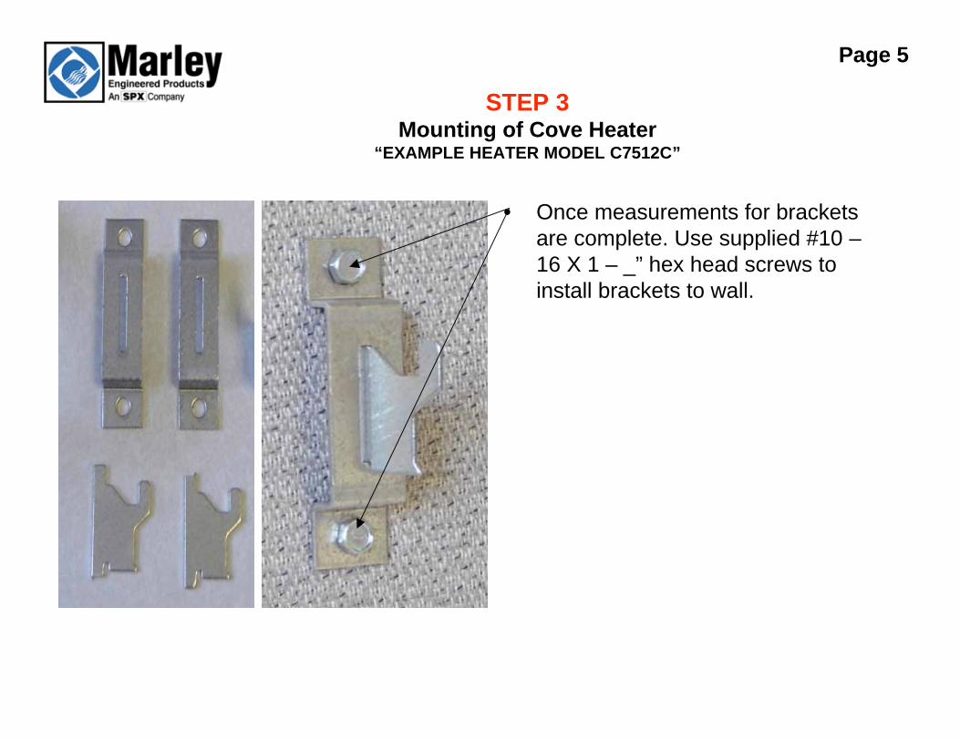
STEP 3Mounting of Cove Heater
“EXAMPLE HEATER MODEL C7512C”
• Once measurements for brackets
are complete. Use supplied #10 –
16 X 1 – _” hex head screws to
install brackets to wall.
Page 5

STEP 4Mounting of Cove Heater
“EXAMPLE HEATER MODEL C7512C”
• Locate a wall stud between the
two mounted end brackets.
• Use mounting bracket template for
marking of center bracket location.
(Use center bracket holes on
template)
Page 6
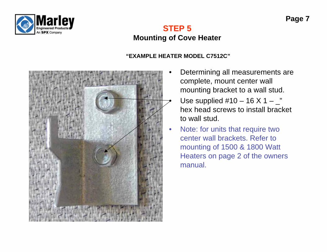
STEP 5Mounting of Cove Heater
“EXAMPLE HEATER MODEL C7512C” • Determining all measurements are
complete, mount center wall
mounting bracket to a wall stud.
• Use supplied #10 – 16 X 1 – _”
hex head screws to install bracket
to wall stud.
• Note: for units that require two
center wall brackets. Refer to
mounting of 1500 & 1800 Watt
Heaters on page 2 of the owners
manual.
Page 7

STEP 6Mounting of Cove Heater
“EXAMPLE HEATER MODEL C7512C”
• Use the most convenient of the
two knock outs available to feed
supply wires into the junction box
of the heater.
• Knock out should be removed
prior to hanging the heater on the
wall.
• Customers will need to provide
appropriate size wire connector.
Page 8
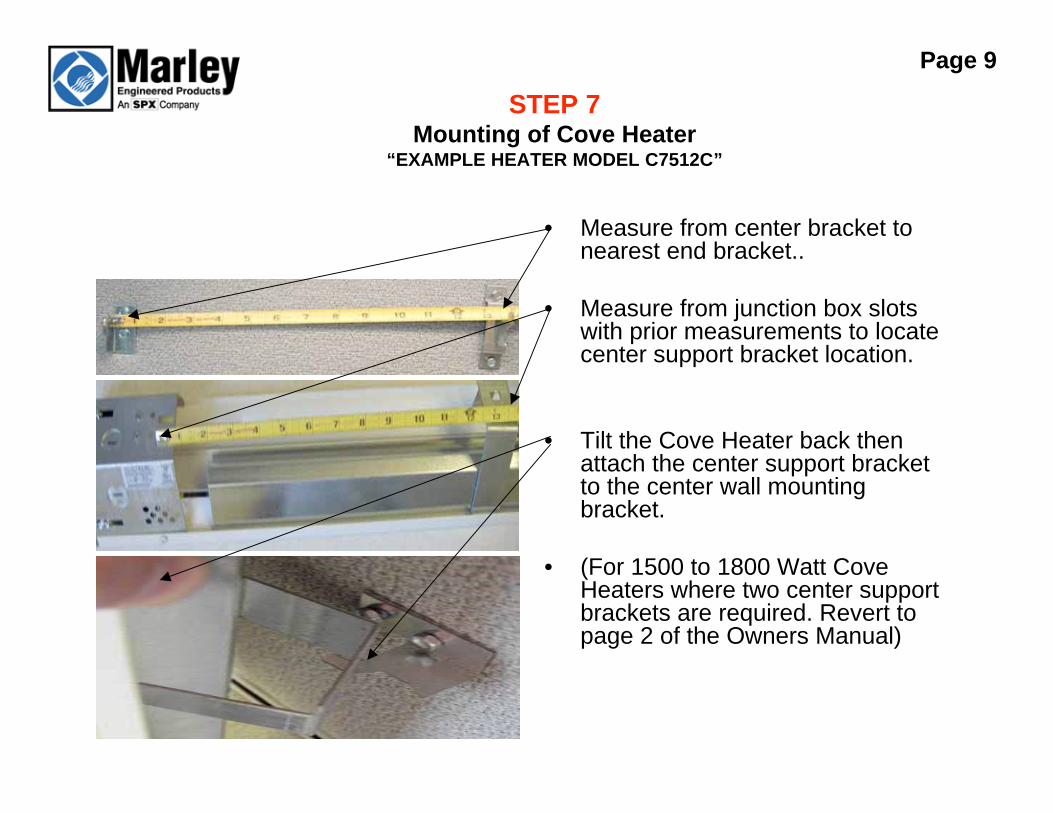
STEP 7Mounting of Cove Heater
“EXAMPLE HEATER MODEL C7512C”
• Measure from center bracket tonearest end bracket..
• Measure from junction box slotswith prior measurements to locatecenter support bracket location.
• Tilt the Cove Heater back thenattach the center support bracketto the center wall mountingbracket.
• (For 1500 to 1800 Watt CoveHeaters where two center supportbrackets are required. Revert topage 2 of the Owners Manual)
Page 9
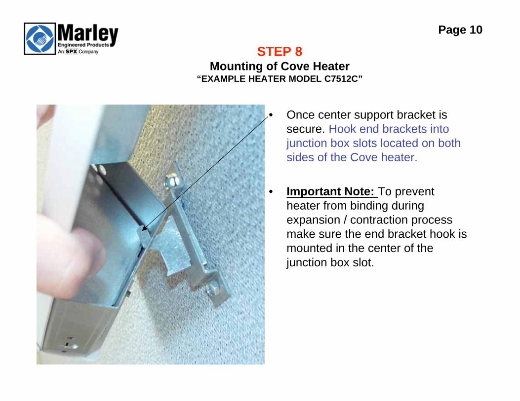
STEP 8Mounting of Cove Heater
“EXAMPLE HEATER MODEL C7512C”
• Once center support bracket is
secure. Hook end brackets into
junction box slots located on both
sides of the Cove heater.
• Important Note: To prevent
heater from binding during
expansion / contraction process
make sure the end bracket hook is
mounted in the center of the
junction box slot.
Page 10

STEP 1 Wiring of Cove Heater
“EXAMPLE HEATER MODEL C7512C”
• Cove Heaters can be wired on the
left or the right end of the heater.
• “Note example heater is 120 volts”
• Wiring diagrams below are for
single heaters, when wiring
multiple heaters refer to figure 5
on page 3 of owners manual.
Page 11

STEP 2Wiring of Cove Heater
“EXAMPLE HEATER MODEL C7512C”
• Wiring the side of the heater theSupply Power is NOT fed into.
• Green ground wire shall becapped off with wire nut.
• Yellow element wire shall be wiredto the white crossover wire.
• Red crossover wire shall becapped off with wire nut “Note redcrossover wire is for multipleheater wiring”
• Note for 240 volt heaters theelement wire is RED.
Page 12
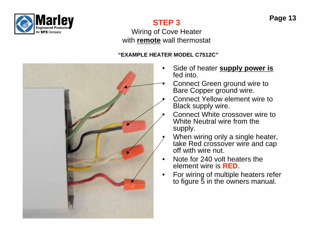
STEP 3Wiring of Cove Heater
with remote wall thermostat
“EXAMPLE HEATER MODEL C7512C”
• Side of heater supply power isfed into.
• Connect Green ground wire toBare Copper ground wire.
• Connect Yellow element wire toBlack supply wire.
• Connect White crossover wire toWhite Neutral wire from thesupply.
• When wiring only a single heater,take Red crossover wire and capoff with wire nut.
• Note for 240 volt heaters theelement wire is RED.
• For wiring of multiple heaters referto figure 5 in the owners manual.
Page 13

STEP 1Wiring of Cove Heater
with internal thermostat accessory “EXAMPLE HEATER MODEL C7512C”
• Remove the thermostat knock out,
at the bottom on the appropriate
end of the heater.
• Use the mounting hardware
provided with the thermostat to
install the thermostat to the cove
heater.
Page 14

STEP 2Wiring of Cove Heater
with internal thermostat accessory “EXAMPLE HEATER MODEL C7512C”
• Connect Green ground wire to BareCopper ground wire.
• Connect Yellow element wire to onethermostat Black wire.
• Connect Black supply wire toremaining Black thermostat wire.
• Connect White crossover wire toWhite Neutral wire from supply.
• Cap off the Red crossover wire “forwiring multiple heaters only”
• Note for 240 volt heaters theelement wire is RED.
Page 15

Finishing Up
• Using provided painted screws
secure end caps to the cove
heater. (Note: it is important to
carefully fold wiring back into
wiring compartment making sure
wires do not get between
fiberboard and front extrusion.)
• Place the thermostat knob on the
shaft of the thermostat.
Page 16