Embed Size (px)
Citation preview
REFRIGERATION ANDAIR CONDITIONING
M O U N T I N G I N S T R U C T I O N SF O R D A N F O S S C O M P R E S S O R S
1
C O N T E N T S
M O U N T I N G
I N S T R U C T I O N S
F O R 2 2 0 - 2 4 0 V
A N D 1 1 5 - 1 2 7 V
C O M P R E S S O R E S
1 . 0 G E N E R A L
2 . 0 C O M P R E S S O R
2.1 Denomination
2.2 Low and high starting torque
2.3 Motor protector
2.4 Rubber grommets
2.5 Minimum ambient temperature
3 . 0 F A U L T F I N D I N G
3.1 Winding protector cut out
3.2 PTC and protector interaction
3.3 Check of winding protector and resistance
4 . 0 O P E N I N G T H E R E F R I G E R A T I N G
S Y S T E M
4.1 Flammable refrigerants
5 . 0 M O U N T I N G
5.1 Connectors
5.2 Drifting out connectors
5.3 Tube adapters
5.4 Solders
5.5 Soldering
5.6 Lokring connections
5.7 Driers
5.8 Driers and refrigerants
5.9 Capillary tube in drier
6 . 0 E L E C T R I C A L E Q U I P M E N T
6.1 LST starting device
6.2 HST starting equipment
6.3 HST CSR starting equipment
6.4 Equipment for SC Twin compressors
6.5 Electronic unit for variable speed compressors
7 . 0 E V A C U A T I O N
7.1 Vacuum pumps
8 . 0 C H A R G I N G O F R E F R I G E R A N T
8.1 Maximum refrigerant charge
8.2 Closing the process tube
9 . 0 T E S T I N G
9.1 Testing of the appliance
D a n f o s s C o m p r e s s o r s
This leaflet is for service technicians installing compressors in hermetic
refrigerating systems using refrigerants R12, R134a, R290, R404A/R507,
R407C and R600a.
3D a n f o s s C o m p r e s s o r s
When a compressor has to be installed in new appliancesnormally sufficient time is available to choose the rightcompressor type from datasheets and make sufficienttesting.Contrary when a faulty compressor has to be replaced itcan in many cases be impossible to get the same com-pressor type as the original.In such cases it is necessary to compare relevantcompressor catalogue data.Long lifetime for a compressor can be expected if the
service work is done in the right way and cleannessand dryness of the components are taken into considera-tion.The service technician has to observe the following whenchoosing a compressor.Type of refrigerant, voltage and frequency, applicationrange, compressor displacement/capacity, starting con-ditions and cooling conditions.If possible use the same refrigerant type as in the faultysystem.
The programme of Danfoss compressors consists of thebasic types P, T, N, F, SC and SC Twin.
1 .G E N E R A L
2 .COMPRESSOR
102H
4635
TLES6KK.2220-240V~50HzLBP LST
8375
-9
DANFOSS COMPRESSORS
Application
Barcode onwhite background
Yellow background
Red stripe
Approvals
R600aSUCTIONCONNECTOR
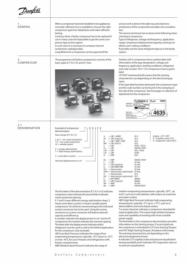
Danfoss 220 V compressors have a yellow label withinformation of the type designation, voltage andfrequency, application, starting conditions, refrigerantand code number. The 115 V compressors have a greenlabel.LST/HST mentioned both means that the startingcharacteristics are depending on the electrical equip-ment.If the type label has been destroyed, the compressor typeand the code number can be found in the stamping onthe side of the compressor. See first pages in collection ofdatasheets for the compressor.
Example of compressordenomination
The first letter of the denomination (P, T, N, F or S) indicatescompressor series whereas the second letter indicatesmotor protection placing.E, Y and X mean different energy optimization steps. Smeans semi direct suction. V means variable speedcompressors. On all these mentioned types the indicatedsuction connector has to be used. Using the wrongconnector as suction connector will lead to reducedcapacity and efficiency.A number indicates the displacement in cm3, but for PLcompressors the number indicates the nominal capacity.The letter after the displacement indicates whichrefrigerant must be used as well as the field of applicationfor the compressor. (See example)LBP (Low Back Pressure) indicates the range of lowevaporating temperatures, typically -10°C down to -35°Cor even -45°C,for use in freezers and refrigerators withfreezer compartments.MBP (Medium Back Pressure) indicates the range of
2 .1DENOMINATION
Basic design (P, T, N, F, S)
L, R, C = int. motor protectionT, F = ext. motor protectionLV = variable speed
E = energy optimizationY = High energy optimization
S = semi direct suction
Nominal displacement in cm3
A = LBP / (MBP) R12AT = LBP (tropical) R12B = LBP / MBP / HBP R12BM = LBP (240 V) R22C = LBP R502 / (R22)CL = LBP R404A/ R507CM = LBP R22 / R502CN = LBP R290D = HBP R22
DL = HBP R404A/ R507F = LBP R134aFT = LBP (tropical) R134aG = LBP/MBP/HBP R134aGH = Heat pumps R134aGHH = Heat pumps (optimized) R134aH = Heat pumps R12HH = Heat pumps (optimized) R12K = LBP/(MBP) R600aKT = LBP (tropical) R600aMF = MBP R134aML = MBP R404A/R507
empty = LST / HSTK = Capillary tube (LST)X = Expansion valve (HST)
T L E S 4 F K
medium evaporating temperatures, typically -20°C upto 0°C, such as in cold cabinets, milk coolers, ice machinesand water coolers.HBP (High Back Pressure) indicates high evaporatingtemperatures, typically -5°C up to +15°C, such as indehumidifiers and some liquid coolers.T as extra character indicates a compressor intended fortropical application. This means high ambient tempera-tures and capability of working with more unstablepower supply.The final letter in the compressor denomination providesinformation on the starting torque. If, as principal rule,the compressor is intended for LST (Low Starting Torque)and HST (High Starting Torque), the place is left empty.The starting characteristics are depending on theelectrical equipment chosen.K indicates LST (capillary tube and pressure equalizationduring standstill) and X indicates HST (expansion valve orno pressure equalization).
4D a n f o s s C o m p r e s s o r s
Description of the different electrical equipments showncan be found in the datasheets for the compressors. Seealso section 6.0.Low starting torque (LST) compressors must only be usedin refrigerating systems having capillary tube throttlingdevice where pressure equalization is obtained betweensuction and discharge sides during each standstill period.A PTC starting device (LST) requires that the standstilltime is at least 5 minutes, since this is the time necessaryfor cooling the PTC.The HST starting device, which gives the compressor a
2 .2LOW AND HIGHSTAR TING TORQUE
high starting torque, must always be used in refrige–ration systems with expansion valve, and for capillarytube systems without full pressure equalization beforeeach start.High stating torque (HST) compressors are normally usinga relay and starting capacitor as starting device.The starting capacitors are designed for short time cut-in.“1.7% ED”, which is stamped onto the starting capacitor,means for instance max. 10 cut-ins per hour each with aduration of 6 seconds.
Most of the Danfoss compressors are equipped with abuilt-in motor protector (winding protector) in the motorwindings. See also section 2.1.At peak load the winding temperature must not exceed
2.3MOTOR PROTEC TORAND WINDINGTEMPER ATURE
135°C and at stable conditions the winding temperaturemust not exceed 125°C. Specific information on somespecial types can be found in the collection of datasheets.
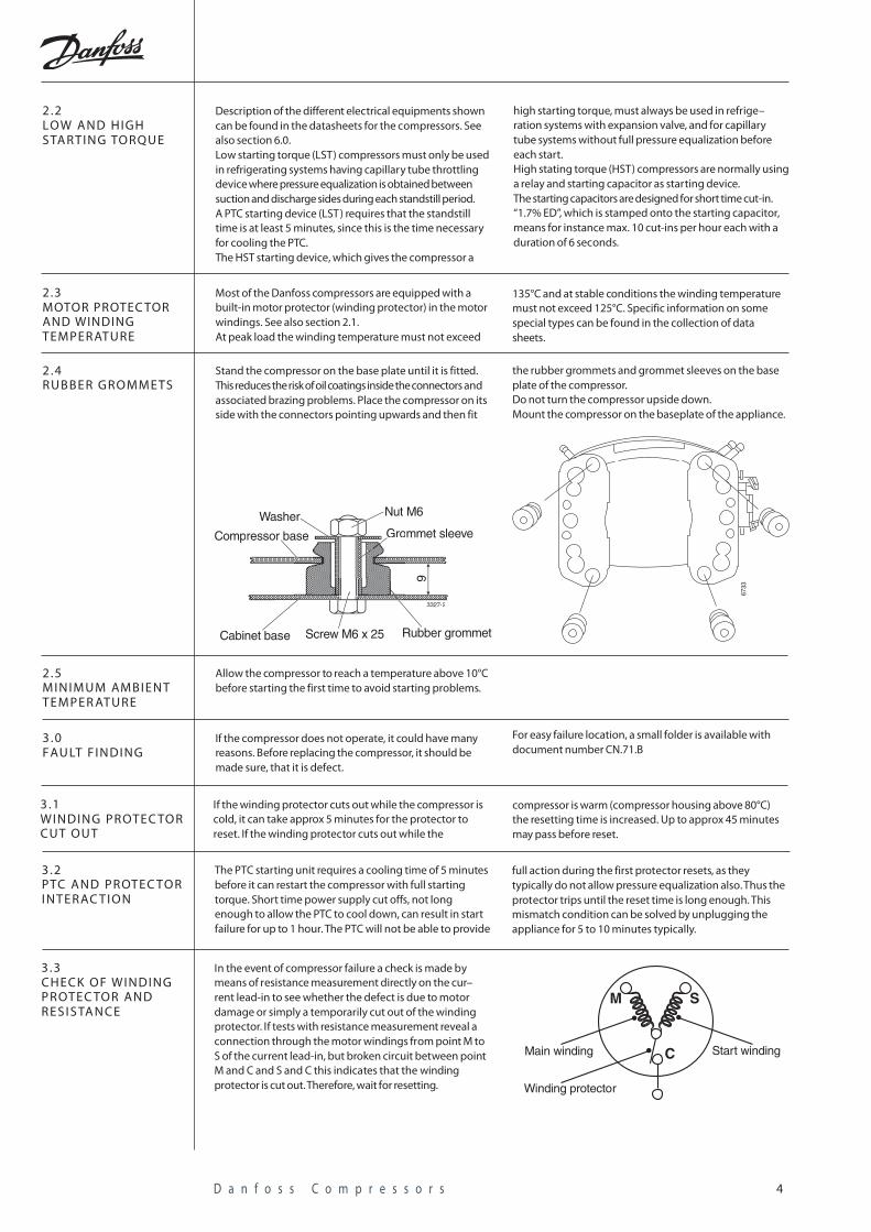
Stand the compressor on the base plate until it is fitted.This reduces the risk of oil coatings inside the connectors andassociated brazing problems. Place the compressor on itsside with the connectors pointing upwards and then fit
2 .4RUBBER GROMMETS
3327-2
9
Compressor base Grommet sleeveWasher Nut M6
Cabinet base Screw M6 x 25 Rubber grommet
6733
the rubber grommets and grommet sleeves on the baseplate of the compressor.Do not turn the compressor upside down.Mount the compressor on the baseplate of the appliance.
Allow the compressor to reach a temperature above 10°Cbefore starting the first time to avoid starting problems.
2 .5MINIMUM AMBIENTTEMPER ATURE
If the compressor does not operate, it could have manyreasons. Before replacing the compressor, it should bemade sure, that it is defect.
3 .0FAU LT FINDING
If the winding protector cuts out while the compressor iscold, it can take approx 5 minutes for the protector toreset. If the winding protector cuts out while the
3 .1WINDING PROTEC TO RCUT OUT
compressor is warm (compressor housing above 80°C)the resetting time is increased. Up to approx 45 minutesmay pass before reset.
The PTC starting unit requires a cooling time of 5 minutesbefore it can restart the compressor with full startingtorque. Short time power supply cut offs, not longenough to allow the PTC to cool down, can result in startfailure for up to 1 hour. The PTC will not be able to provide
3 .2PTC AND PROTEC TO RINTERAC TION
full action during the first protector resets, as theytypically do not allow pressure equalization also. Thus theprotector trips until the reset time is long enough. Thismismatch condition can be solved by unplugging theappliance for 5 to 10 minutes typically.
In the event of compressor failure a check is made bymeans of resistance measurement directly on the cur–rent lead-in to see whether the defect is due to motordamage or simply a temporarily cut out of the windingprotector. If tests with resistance measurement reveal aconnection through the motor windings from point M toS of the current lead-in, but broken circuit between pointM and C and S and C this indicates that the windingprotector is cut out. Therefore, wait for resetting.
3 .3CHECK OF WINDINGP R OTEC TOR ANDR E S I S TA N C E
M S
CMain winding Start winding
Winding protector
For easy failure location, a small folder is available withdocument number CN.71.B
5D a n f o s s C o m p r e s s o r s
Never open a refrigerating system before all componentsfor the repair are available. Compressor, drier and othersystem components must be sealed off until a continuousassembly can occur.Opening a defect system must be done in different waysdepending on the refrigerant used.
4 .0OPENING THE RE-FRIGER ATING SYSTEM
Fit a service valve to the system and collect the refrige-rant in the right way.If the refrigerant is flammable it can be released outsidein the open air through a hose if the amount is very limit-ed. Then flush the system with dry nitrogen.
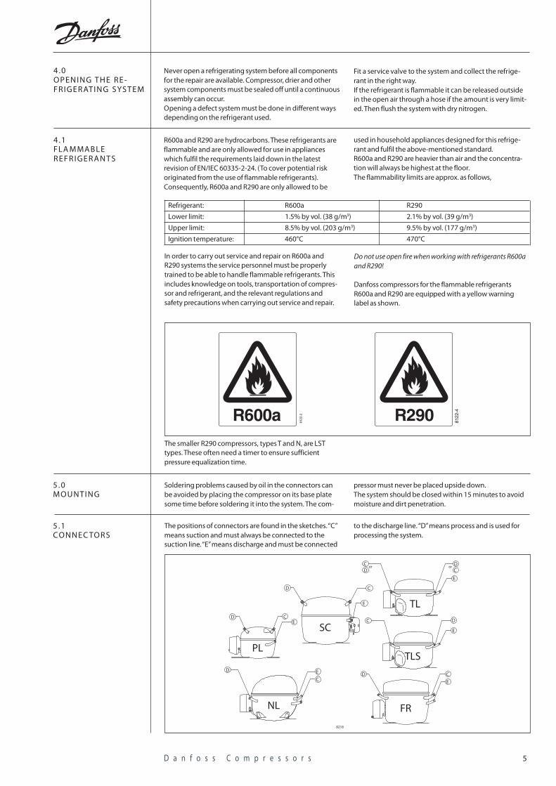
R600a and R290 are hydrocarbons. These refrigerants areflammable and are only allowed for use in applianceswhich fulfil the requirements laid down in the latestrevision of EN/IEC 60335-2-24. (To cover potential riskoriginated from the use of flammable refrigerants).Consequently, R600a and R290 are only allowed to be
4 .1FLA MMABLEREFRIGERANTS
Refrigerant: R600a R290
Lower limit: 1.5% by vol. (38 g/m3) 2.1% by vol. (39 g/m3)
Upper limit: 8.5% by vol. (203 g/m3) 9.5% by vol. (177 g/m3)
Ignition temperature: 460°C 470°C
In order to carry out service and repair on R600a andR290 systems the service personnel must be properlytrained to be able to handle flammable refrigerants. Thisincludes knowledge on tools, transportation of compres-sor and refrigerant, and the relevant regulations andsafety precautions when carrying out service and repair.
Do not use open fire when working with refrigerants R600aand R290!
Danfoss compressors for the flammable refrigerantsR600a and R290 are equipped with a yellow warninglabel as shown.
used in household appliances designed for this refrige-rant and fulfil the above-mentioned standard.R600a and R290 are heavier than air and the concentra-tion will always be highest at the floor.The flammability limits are approx. as follows,
8122
-2R600a 8122
-4R290
Soldering problems caused by oil in the connectors canbe avoided by placing the compressor on its base platesome time before soldering it into the system. The com-
5 .0MOUNTING
pressor must never be placed upside down.The system should be closed within 15 minutes to avoidmoisture and dirt penetration.
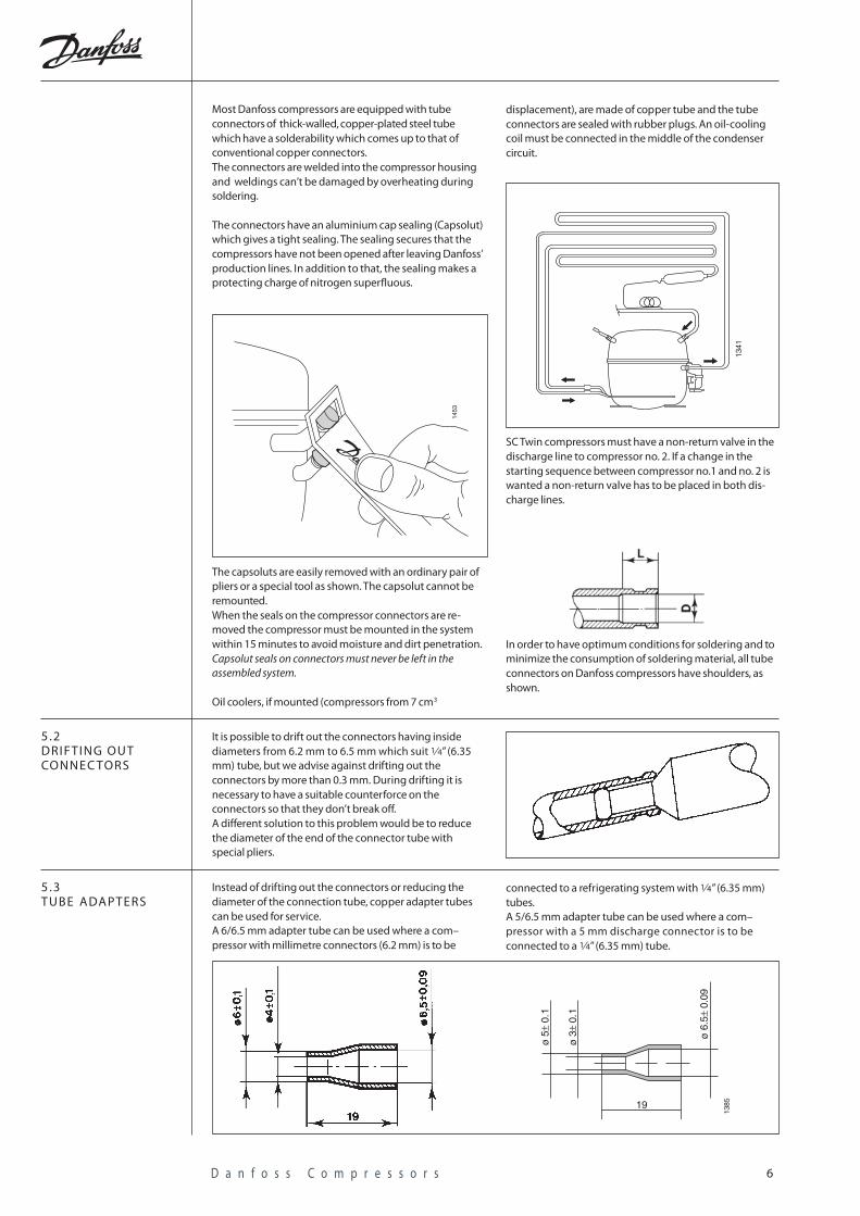
5 .1CONNEC TORS
The positions of connectors are found in the sketches. “C”means suction and must always be connected to thesuction line. “E” means discharge and must be connected
to the discharge line. “D” means process and is used forprocessing the system.
The smaller R290 compressors, types T and N, are LSTtypes. These often need a timer to ensure sufficientpressure equalization time.
8218
TL
E
Cor
DD
orC
PL
CE
D
NL
C
ED
FR
E
CD
SC
D C
E
C D
E
TLS
6D a n f o s s C o m p r e s s o r s
displacement), are made of copper tube and the tubeconnectors are sealed with rubber plugs. An oil-coolingcoil must be connected in the middle of the condensercircuit.
SC Twin compressors must have a non-return valve in thedischarge line to compressor no. 2. If a change in thestarting sequence between compressor no.1 and no. 2 iswanted a non-return valve has to be placed in both dis-charge lines.
In order to have optimum conditions for soldering and tominimize the consumption of soldering material, all tubeconnectors on Danfoss compressors have shoulders, asshown.
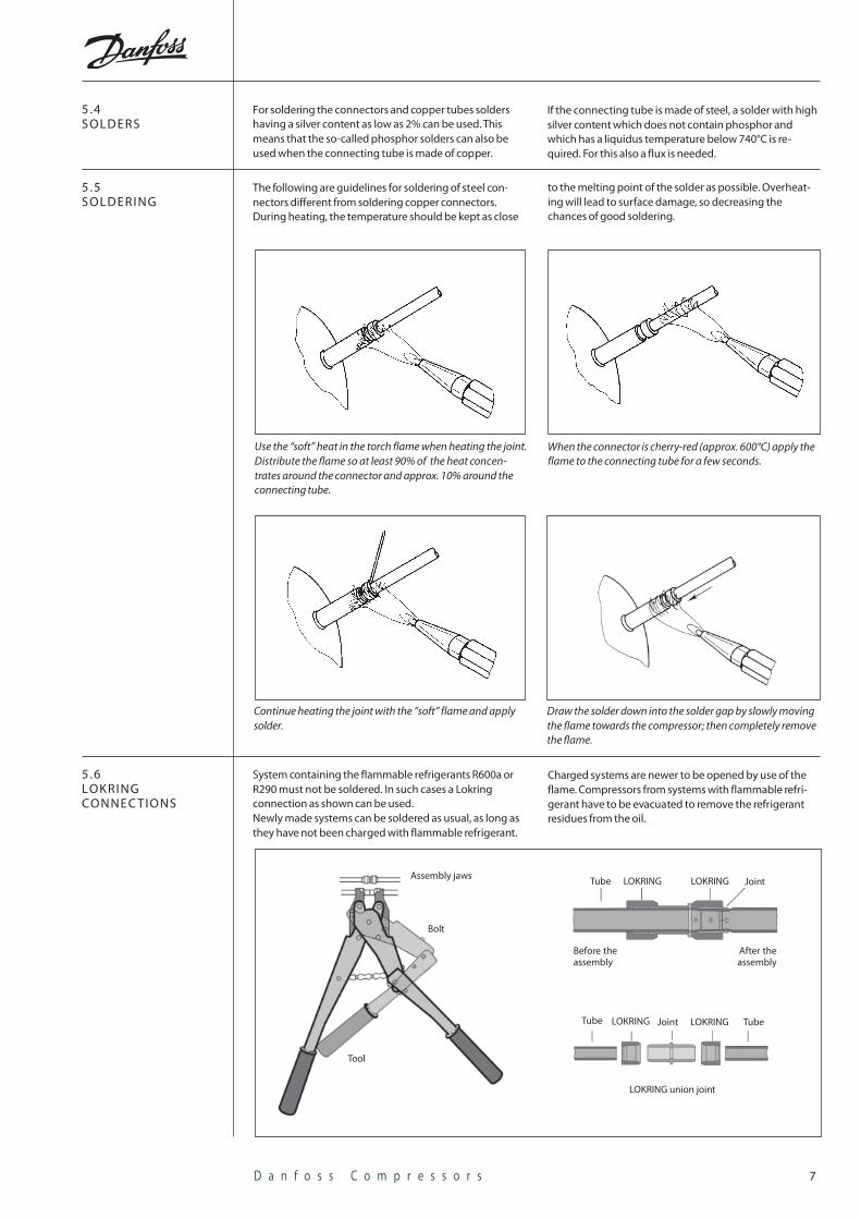
Most Danfoss compressors are equipped with tubeconnectors of thick-walled, copper-plated steel tubewhich have a solderability which comes up to that ofconventional copper connectors.The connectors are welded into the compressor housingand weldings can’t be damaged by overheating duringsoldering.
The connectors have an aluminium cap sealing (Capsolut)which gives a tight sealing. The sealing secures that thecompressors have not been opened after leaving Danfoss’production lines. In addition to that, the sealing makes aprotecting charge of nitrogen superfluous.
The capsoluts are easily removed with an ordinary pair ofpliers or a special tool as shown. The capsolut cannot beremounted.When the seals on the compressor connectors are re-moved the compressor must be mounted in the systemwithin 15 minutes to avoid moisture and dirt penetration.Capsolut seals on connectors must never be left in theassembled system.
Oil coolers, if mounted (compressors from 7 cm3
1453
1341
It is possible to drift out the connectors having insidediameters from 6.2 mm to 6.5 mm which suit 1⁄4” (6.35mm) tube, but we advise against drifting out theconnectors by more than 0.3 mm. During drifting it isnecessary to have a suitable counterforce on theconnectors so that they don’t break off.A different solution to this problem would be to reducethe diameter of the end of the connector tube withspecial pliers.
5 .2DRIFTING OUTCONNEC TORS
Instead of drifting out the connectors or reducing thediameter of the connection tube, copper adapter tubescan be used for service.A 6/6.5 mm adapter tube can be used where a com–pressor with millimetre connectors (6.2 mm) is to be
5 .3TUBE ADAPTERS
connected to a refrigerating system with 1⁄4” (6.35 mm)tubes.A 5/6.5 mm adapter tube can be used where a com–pressor with a 5 mm discharge connector is to beconnected to a 1⁄4” (6.35 mm) tube.
ø 5
± 0.
1
ø 3
± 0.
1
ø 6
.5±
0.09
19
1385
7D a n f o s s C o m p r e s s o r s
For soldering the connectors and copper tubes soldershaving a silver content as low as 2% can be used. Thismeans that the so-called phosphor solders can also beused when the connecting tube is made of copper.
5 .4SOLDERS
If the connecting tube is made of steel, a solder with highsilver content which does not contain phosphor andwhich has a liquidus temperature below 740°C is re-quired. For this also a flux is needed.
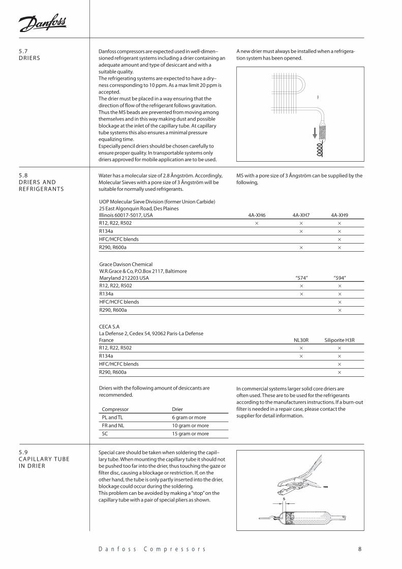
The following are guidelines for soldering of steel con-nectors different from soldering copper connectors.During heating, the temperature should be kept as close
5 .5SOLDERING
Use the “soft” heat in the torch flame when heating the joint.Distribute the flame so at least 90% of the heat concen-trates around the connector and approx. 10% around theconnecting tube.
When the connector is cherry-red (approx. 600°C) apply theflame to the connecting tube for a few seconds.
Continue heating the joint with the “soft” flame and applysolder.
Draw the solder down into the solder gap by slowly movingthe flame towards the compressor; then completely removethe flame.
to the melting point of the solder as possible. Overheat-ing will lead to surface damage, so decreasing thechances of good soldering.
System containing the flammable refrigerants R600a orR290 must not be soldered. In such cases a Lokringconnection as shown can be used.Newly made systems can be soldered as usual, as long asthey have not been charged with flammable refrigerant.
5 .6LOKRINGCONNEC TIONS
Charged systems are newer to be opened by use of theflame. Compressors from systems with flammable refri-gerant have to be evacuated to remove the refrigerantresidues from the oil.
Assembly jaws
Bolt
Tool
Tube LOKRING LOKRING Joint
After theassembly
Before theassembly
Tube LOKRING LOKRINGJoint Tube
LOKRING union joint
8D a n f o s s C o m p r e s s o r s
Danfoss compressors are expected used in well-dimen–sioned refrigerant systems including a drier containing anadequate amount and type of desiccant and with asuitable quality.The refrigerating systems are expected to have a dry–ness corresponding to 10 ppm. As a max limit 20 ppm isaccepted.The drier must be placed in a way ensuring that thedirection of flow of the refrigerant follows gravitation.Thus the MS beads are prevented from moving amongthemselves and in this way making dust and possibleblockage at the inlet of the capillary tube. At capillarytube systems this also ensures a minimal pressureequalizing time.Especially pencil driers should be chosen carefully toensure proper quality. In transportable systems onlydriers approved for mobile application are to be used.
5 .7DRIERS
7469
Water has a molecular size of 2.8 Ångström. Accordingly,Molecular Sieves with a pore size of 3 Ångström will besuitable for normally used refrigerants.
5 .8DRIERS ANDREFRIGERANTS
MS with a pore size of 3 Ångström can be supplied by thefollowing,
UOP Molecular Sieve Division (former Union Carbide)25 East Algonquin Road, Des PlainesIllinois 60017-5017, USA 4A-XH6 4A-XH7 4A-XH9
R12, R22, R502 × × ×R134a × ×HFC/HCFC blends ×R290, R600a × ×
Grace Davison ChemicalW.R.Grace & Co, P.O.Box 2117, BaltimoreMaryland 212203 USA “574” ”594”R12, R22, R502 × ×R134a × ×HFC/HCFC blends ×R290, R600a ×
CECA S.ALa Defense 2, Cedex 54, 92062 Paris-La DefenseFrance NL30R Siliporite H3RR12, R22, R502 × ×R134a × ×HFC/HCFC blends ×R290, R600a ×
Driers with the following amount of desiccants arerecommended.
Compressor Drier
PL and TL 6 gram or more
FR and NL 10 gram or more
SC 15 gram or more
In commercial systems larger solid core driers areoften used. These are to be used for the refrigerantsaccording to the manufacturers instructions. If a burn-outfilter is needed in a repair case, please contact thesupplier for detail information.
Special care should be taken when soldering the capil–lary tube. When mounting the capillary tube it should notbe pushed too far into the drier, thus touching the gaze orfilter disc, causing a blockage or restriction. If, on theother hand, the tube is only partly inserted into the drier,blockage could occur during the soldering.This problem can be avoided by making a “stop” on thecapillary tube with a pair of special pliers as shown.
5 .9CAPILLAR Y TUBEIN DRIER
A new drier must always be installed when a refrigera-tion system has been opened.
9D a n f o s s C o m p r e s s o r s
For information on the right starting devices, please seeDatasheets for the compressor.Never use a starting device of and old compressor,because this may cause a compressor failure.No attempt must be made to start the compressor
6 .0ELEC TRICAL EQUIP-M E N T
without the complete starting equipment. For safetyreasons the compressor must always be earthed orotherwise additionally protected. Keep away inflammablematerial from the electrical equipment.The compressor must not be started under vacuum.
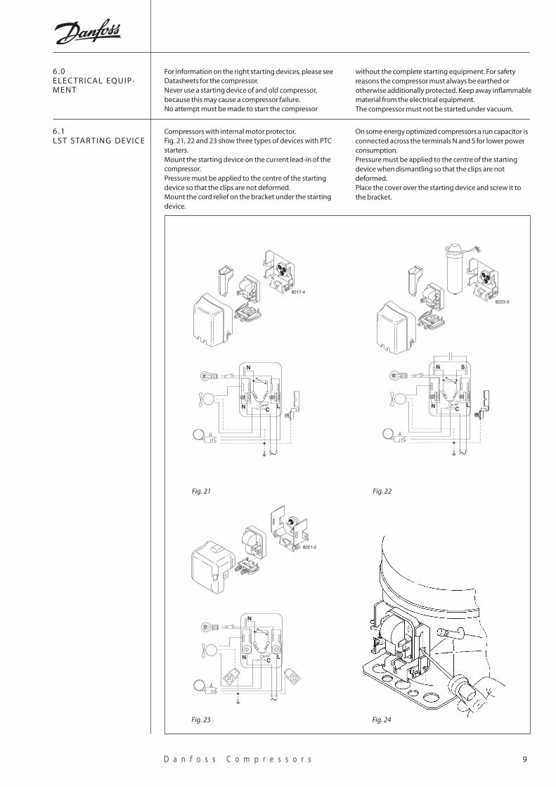
Compressors with internal motor protector.Fig. 21, 22 and 23 show three types of devices with PTCstarters.Mount the starting device on the current lead-in of thecompressor.Pressure must be applied to the centre of the startingdevice so that the clips are not deformed.Mount the cord relief on the bracket under the startingdevice.
6 .1LST STAR TING DE VICE
On some energy optimized compressors a run capacitor isconnected across the terminals N and S for lower powerconsumption.Pressure must be applied to the centre of the startingdevice when dismantling so that the clips are notdeformed.Place the cover over the starting device and screw it tothe bracket.
8217-4
N
N LC
8223-3
N
N LC
S
8221-2
N
N LC
Fig. 21 Fig. 22
Fig. 23 Fig. 24
1 0D a n f o s s C o m p r e s s o r s
8231-2
M
10
5
4
3
2
1
L
N
7
8
6
12
14
13
11
8230-2
M
1012
1113
14
Fig. 25 Fig. 25a
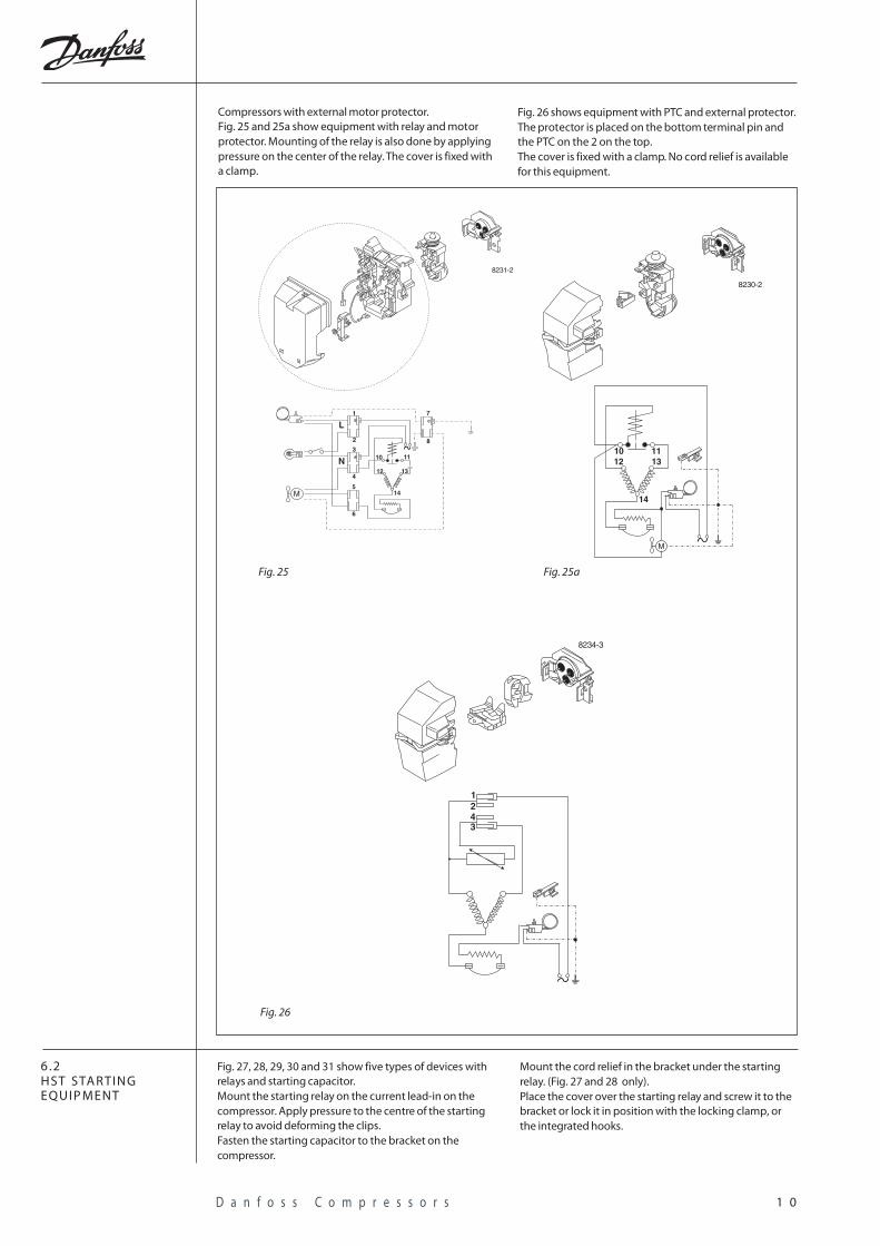
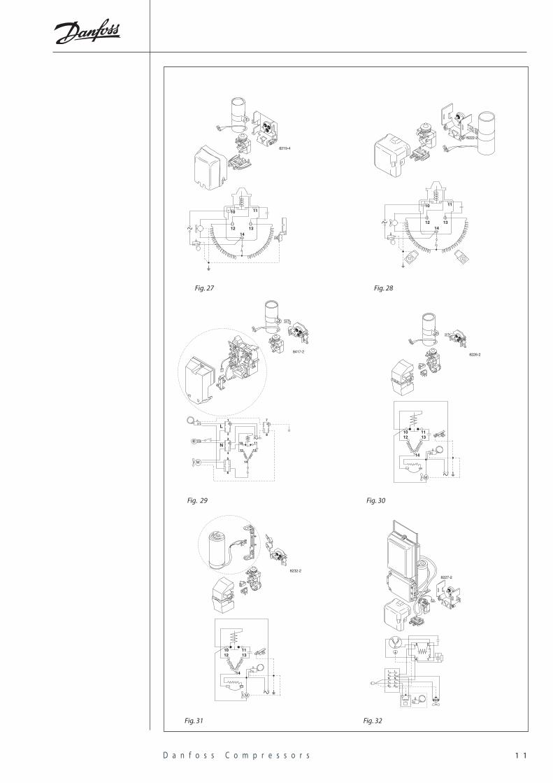
Fig. 27, 28, 29, 30 and 31 show five types of devices withrelays and starting capacitor.Mount the starting relay on the current lead-in on thecompressor. Apply pressure to the centre of the startingrelay to avoid deforming the clips.Fasten the starting capacitor to the bracket on thecompressor.
6 .2HST STAR TINGEQUIP MENT
Mount the cord relief in the bracket under the startingrelay. (Fig. 27 and 28 only).Place the cover over the starting relay and screw it to thebracket or lock it in position with the locking clamp, orthe integrated hooks.
Compressors with external motor protector.Fig. 25 and 25a show equipment with relay and motorprotector. Mounting of the relay is also done by applyingpressure on the center of the relay. The cover is fixed witha clamp.
Fig. 26 shows equipment with PTC and external protector.The protector is placed on the bottom terminal pin andthe PTC on the 2 on the top.The cover is fixed with a clamp. No cord relief is availablefor this equipment.
Fig. 26
8234-3
12
34
1 1D a n f o s s C o m p r e s s o r s
8417-2
M
10
5
4
3
2
1
L
N
7
8
6
12
14
13
11
8226-2
1012
1113
14
M
Fig. 27 Fig. 28
8219-4
10 11
131214
8222-2
10 11
131214
8232-2
1012
1113
14
M
Fig. 29 Fig. 30
Fig. 31
8227-2
M
1 1
2 2N NL L
5
4
2
1
Fig. 32
1 2D a n f o s s C o m p r e s s o r s
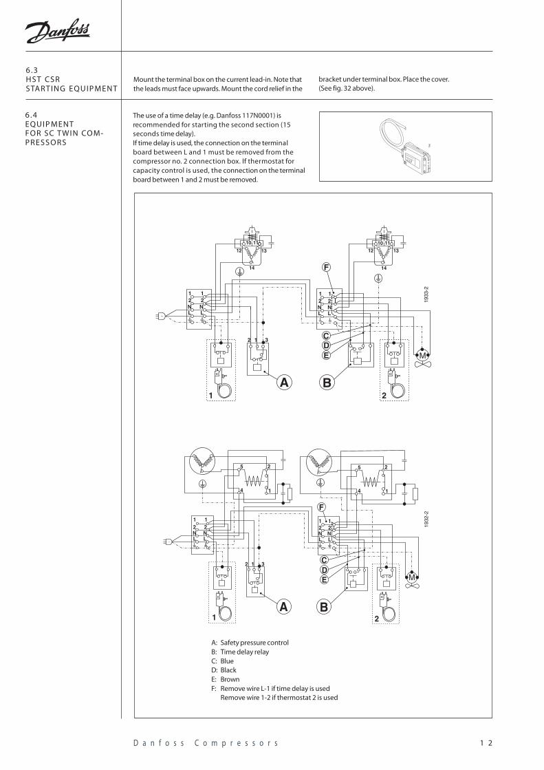
The use of a time delay (e.g. Danfoss 117N0001) isrecommended for starting the second section (15seconds time delay).If time delay is used, the connection on the terminalboard between L and 1 must be removed from thecompressor no. 2 connection box. If thermostat forcapacity control is used, the connection on the terminalboard between 1 and 2 must be removed.
6 .4EQUIP MENTFOR SC TWIN CO M-PRESSORS
7380
1933
-2
M
12
10 11
13
14
12
14
10 11
13
12NL
12NL
1 12 2N NL L
2 1 3
BA1 2
CDE
F
Mount the terminal box on the current lead-in. Note thatthe leads must face upwards. Mount the cord relief in the
6 .3HST CSRSTAR TING EQUIP MENT
bracket under terminal box. Place the cover.(See fig. 32 above).
5 2
14
5 2
14
1 12 2N NL L
1 12 2N NL L
1932
-2
M
B
2 1 3 CDE
2A
F
1
A: Safety pressure controlB: Time delay relayC: BlueD: BlackE: BrownF: Remove wire L-1 if time delay is used
Remove wire 1-2 if thermostat 2 is used
1 3D a n f o s s C o m p r e s s o r s
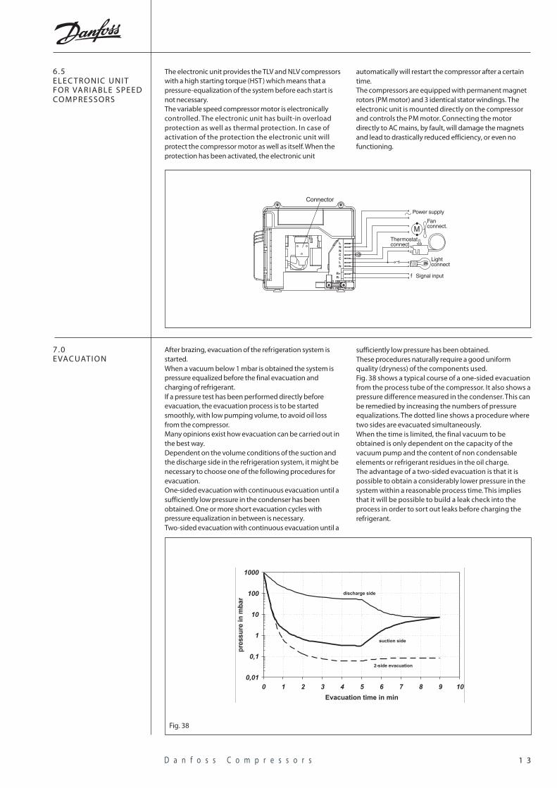
The electronic unit provides the TLV and NLV compressorswith a high starting torque (HST) which means that apressure-equalization of the system before each start isnot necessary.The variable speed compressor motor is electronicallycontrolled. The electronic unit has built-in overloadprotection as well as thermal protection. In case ofactivation of the protection the electronic unit willprotect the compressor motor as well as itself. When theprotection has been activated, the electronic unit
6 .5ELEC TRONIC UNITFOR VARIABLE SPEEDCOMPRESSORS
automatically will restart the compressor after a certaintime.The compressors are equipped with permanent magnetrotors (PM motor) and 3 identical stator windings. Theelectronic unit is mounted directly on the compressorand controls the PM motor. Connecting the motordirectly to AC mains, by fault, will damage the magnetsand lead to drastically reduced efficiency, or even nofunctioning.
Power supply
Fanconnect.
Thermostatconnect.
Lightconnect
Signal input
Connector
M
f
LNNCCLN
R+R-
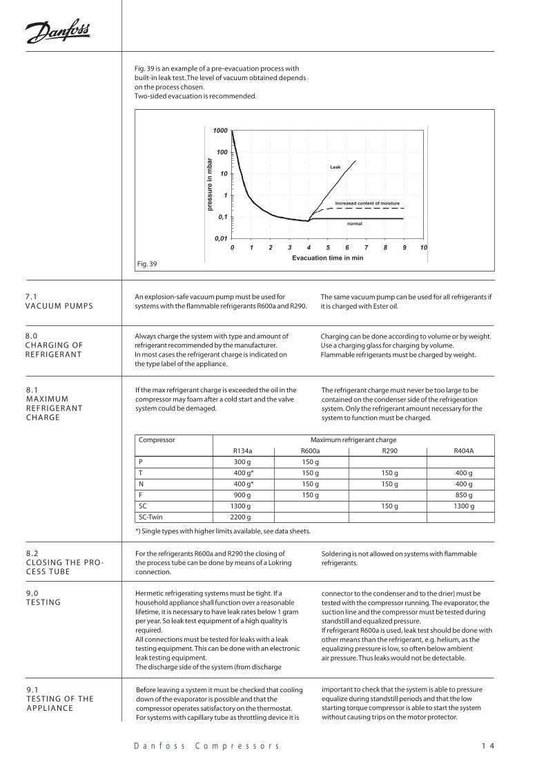
After brazing, evacuation of the refrigeration system isstarted.When a vacuum below 1 mbar is obtained the system ispressure equalized before the final evacuation andcharging of refrigerant.If a pressure test has been performed directly beforeevacuation, the evacuation process is to be startedsmoothly, with low pumping volume, to avoid oil lossfrom the compressor.Many opinions exist how evacuation can be carried out inthe best way.Dependent on the volume conditions of the suction andthe discharge side in the refrigeration system, it might benecessary to choose one of the following procedures forevacuation.One-sided evacuation with continuous evacuation until asufficiently low pressure in the condenser has beenobtained. One or more short evacuation cycles withpressure equalization in between is necessary.Two-sided evacuation with continuous evacuation until a
7 .0EVAC UATION
sufficiently low pressure has been obtained.These procedures naturally require a good uniformquality (dryness) of the components used.Fig. 38 shows a typical course of a one-sided evacuationfrom the process tube of the compressor. It also shows apressure difference measured in the condenser. This canbe remedied by increasing the numbers of pressureequalizations. The dotted line shows a procedure wheretwo sides are evacuated simultaneously.When the time is limited, the final vacuum to beobtained is only dependent on the capacity of thevacuum pump and the content of non condensableelements or refrigerant residues in the oil charge.The advantage of a two-sided evacuation is that it ispossible to obtain a considerably lower pressure in thesystem within a reasonable process time. This impliesthat it will be possible to build a leak check into theprocess in order to sort out leaks before charging therefrigerant.
Fig. 38
1 4D a n f o s s C o m p r e s s o r s
If the max refrigerant charge is exceeded the oil in thecompressor may foam after a cold start and the valvesystem could be demaged.
8 .1MAXIMUMREFRIGERANTCHARGE
The refrigerant charge must never be too large to becontained on the condenser side of the refrigerationsystem. Only the refrigerant amount necessary for thesystem to function must be charged.
Compressor Maximum refrigerant charge
R134a R600a R290 R404A
P 300 g 150 g
T 400 g* 150 g 150 g 400 g
N 400 g* 150 g 150 g 400 g
F 900 g 150 g 850 g
SC 1300 g 150 g 1300 g
SC-Twin 2200 g
For the refrigerants R600a and R290 the closing ofthe process tube can be done by means of a Lokringconnection.
8 .2CLOSING THE PRO -CESS TUBE
Soldering is not allowed on systems with flammablerefrigerants.
Hermetic refrigerating systems must be tight. If ahousehold appliance shall function over a reasonablelifetime, it is necessary to have leak rates below 1 gramper year. So leak test equipment of a high quality isrequired.All connections must be tested for leaks with a leaktesting equipment. This can be done with an electronicleak testing equipment.The discharge side of the system (from discharge
9 .0TESTING
connector to the condenser and to the drier) must betested with the compressor running. The evaporator, thesuction line and the compressor must be tested duringstandstill and equalized pressure.If refrigerant R600a is used, leak test should be done withother means than the refrigerant, e.g. helium, as theequalizing pressure is low, so often below ambientair pressure. Thus leaks would not be detectable.
Before leaving a system it must be checked that coolingdown of the evaporator is possible and that thecompressor operates satisfactory on the thermostat.For systems with capillary tube as throttling device it is
9 .1TESTING OF THEAPPLIANCE
important to check that the system is able to pressureequalize during standstill periods and that the lowstarting torque compressor is able to start the systemwithout causing trips on the motor protector.
*) Single types with higher limits available, see data sheets.
An explosion-safe vacuum pump must be used forsystems with the flammable refrigerants R600a and R290.
7 .1VA CUUM PUMPS
The same vacuum pump can be used for all refrigerants ifit is charged with Ester oil.
Always charge the system with type and amount ofrefrigerant recommended by the manufacturer.In most cases the refrigerant charge is indicated onthe type label of the appliance.
8 .0CHARGING OFREFRIGERANT
Charging can be done according to volume or by weight.Use a charging glass for charging by volume.Flammable refrigerants must be charged by weight.
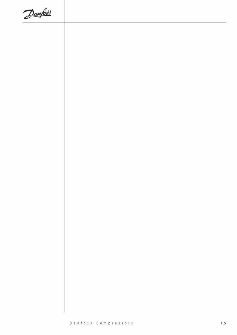
Fig. 39 is an example of a pre-evacuation process withbuilt-in leak test. The level of vacuum obtained dependson the process chosen.Two-sided evacuation is recommended.
Fig. 39
1 5D a n f o s s C o m p r e s s o r s
CF.60.A1.02 Producet by G1 advertising agency. 03.11.LN.LDS.RO
For further information please visit:www.danfoss.com/compressors
Danfoss Compressors GmbHMads-Clausen-Strasse 7
P.O.Box 1443, D-24939 Flensburg
Tel: +49 461 4941-0
Fax: +49 461 44715