Embed Size (px)
Citation preview
System 6000
Electropneumatic Converterfor direct current signalsi/p Converter Type 6116
Mounting andOperating Instructions
EB 6116 ENEdition September 2006
Fig. 1 · Type 6116
Contents Page
1 Description . . . . . . . . . . . . . . . . . . . . . . . . . . . . . . . 61.1 Application. . . . . . . . . . . . . . . . . . . . . . . . . . . . . . . 61.2 Versions . . . . . . . . . . . . . . . . . . . . . . . . . . . . . . . . 61.3 Technical data . . . . . . . . . . . . . . . . . . . . . . . . . . . . . 71.4 Principle of operation . . . . . . . . . . . . . . . . . . . . . . . . . . 9
2 Installation . . . . . . . . . . . . . . . . . . . . . . . . . . . . . . 102.1 Mounting position . . . . . . . . . . . . . . . . . . . . . . . . . . . 102.2 Mounting . . . . . . . . . . . . . . . . . . . . . . . . . . . . . . . 102.3 Electrical connection . . . . . . . . . . . . . . . . . . . . . . . . . . 112.4 Pneumatic connection . . . . . . . . . . . . . . . . . . . . . . . . . 12
3 Operation . . . . . . . . . . . . . . . . . . . . . . . . . . . . . . 123.1 Checking zero point and span . . . . . . . . . . . . . . . . . . . . . 12
4 Maintenance . . . . . . . . . . . . . . . . . . . . . . . . . . . . . 144.1 Cleaning the throttle . . . . . . . . . . . . . . . . . . . . . . . . . . 14
5 Servicing explosion-protected devices. . . . . . . . . . . . . . . . . . . 14
6 Positioner attachment . . . . . . . . . . . . . . . . . . . . . . . . . 156.1 Principle of operation . . . . . . . . . . . . . . . . . . . . . . . . . 156.2 Installation . . . . . . . . . . . . . . . . . . . . . . . . . . . . . . 166.2.1 Mounting position of the converter . . . . . . . . . . . . . . . . . . . 166.3 Electrical connection . . . . . . . . . . . . . . . . . . . . . . . . . . 166.4 Pneumatic connection . . . . . . . . . . . . . . . . . . . . . . . . . 166.5 Operation . . . . . . . . . . . . . . . . . . . . . . . . . . . . . . 17
7 Troubleshooting. . . . . . . . . . . . . . . . . . . . . . . . . . . . 21
Dimensional drawing . . . . . . . . . . . . . . . . . . . . . . . . . 22
Certificates . . . . . . . . . . . . . . . . . . . . . . . . . . . . . . 23
2 EB 6116 EN
Contents
EB 6116 EN 3
Safety instructions
� The devices may only be mounted, started up or serviced by fully trainedand qualified personnel, observing the accepted industry codes andpractices. Make sure employees or third persons are not exposed to anydanger.All safety instructions and warnings in these mounting and operatinginstructions, particularly those concerning assembly, start-up andmaintenance, must be observed.
� Explosion-protected versions of this converter may only be operated bypersonnel who have undergone special training or instructions or who areauthorized to work on explosion-protected devices in hazardous areas.Refer to section 5 on Servicing explosion-protected versions.
� Any hazards which could be caused in the device by the signal pressureare to be prevented by means of the appropriate measures.
� Proper shipping and appropriate storage of the device are assumed.
� Note!The device with the CE marking fulfills the requirements of the Directive94/9/EC and the Directive 89/336/EEC.The declaration of conformity is available on request.
4 EB 6116 EN
Article code
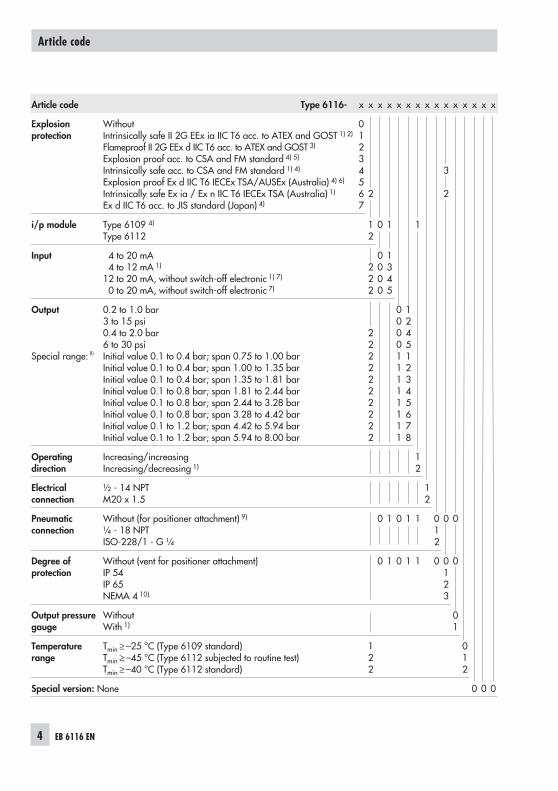
Article code Type 6116- x x x x x x x x x x x x x x x
Explosionprotection
WithoutIntrinsically safe II 2G EEx ia IIC T6 acc. to ATEX and GOST 1) 2)
Flameproof II 2G EEx d IIC T6 acc. to ATEX and GOST 3)
Explosion proof acc. to CSA and FM standard 4) 5)
Intrinsically safe acc. to CSA and FM standard 1) 4)
Explosion proof Ex d IIC T6 IECEx TSA/AUSEx (Australia) 4) 6)
Intrinsically safe Ex ia / Ex n IIC T6 IECEx TSA (Australia) 1)
Ex d IIC T6 acc. to JIS standard (Japan) 4)
01234567
2
3
2
i/p module Type 6109 4)
Type 611212
0 1 1
Input 4 to 20 mA4 to 12 mA 1)
12 to 20 mA, without switch-off electronic 1) 7)
0 to 20 mA, without switch-off electronic 7)
222
0000
1345
Output
Special range: 8)
0.2 to 1.0 bar3 to 15 psi0.4 to 2.0 bar6 to 30 psiInitial value 0.1 to 0.4 bar; span 0.75 to 1.00 barInitial value 0.1 to 0.4 bar; span 1.00 to 1.35 barInitial value 0.1 to 0.4 bar; span 1.35 to 1.81 barInitial value 0.1 to 0.8 bar; span 1.81 to 2.44 barInitial value 0.1 to 0.8 bar; span 2.44 to 3.28 barInitial value 0.1 to 0.8 bar; span 3.28 to 4.42 barInitial value 0.1 to 1.2 bar; span 4.42 to 5.94 barInitial value 0.1 to 1.2 bar; span 5.94 to 8.00 bar
2222222222
000011111111
124512345678
Operatingdirection
Increasing/increasingIncreasing/decreasing 1)
12
Electricalconnection
½ - 14 NPTM20 x 1.5
12
Pneumaticconnection
Without (for positioner attachment) 9)
¼ - 18 NPTISO-228/1 - G ¼
0 1 0 1 1 012
0 0
Degree ofprotection
Without (vent for positioner attachment)IP 54IP 65NEMA 4 10)
0 1 0 1 1 0 0123
0
Output pressuregauge
WithoutWith 1)
01
Temperaturerange
Tmin ≥ –25 °C (Type 6109 standard)Tmin ≥ –45 °C (Type 6112 subjected to routine test)Tmin ≥ –40 °C (Type 6112 standard)
122
012
Special version: None 0 0 0
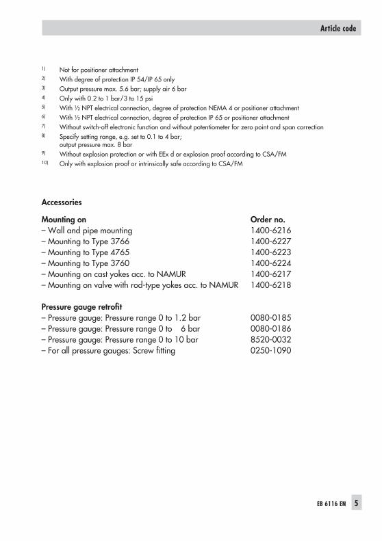
1) Not for positioner attachment2) With degree of protection IP 54/IP 65 only3) Output pressure max. 5.6 bar; supply air 6 bar4) Only with 0.2 to 1 bar/3 to 15 psi5) With ½ NPT electrical connection, degree of protection NEMA 4 or positioner attachment6) With ½ NPT electrical connection, degree of protection IP 65 or positioner attachment7) Without switch-off electronic function and without potentiometer for zero point and span correction8) Specify setting range, e.g. set to 0.1 to 4 bar;
output pressure max. 8 bar9) Without explosion protection or with EEx d or explosion proof according to CSA/FM10) Only with explosion proof or intrinsically safe according to CSA/FM
Accessories
Mounting on Order no.– Wall and pipe mounting 1400-6216– Mounting to Type 3766 1400-6227– Mounting to Type 4765 1400-6223– Mounting to Type 3760 1400-6224– Mounting on cast yokes acc. to NAMUR 1400-6217– Mounting on valve with rod-type yokes acc. to NAMUR 1400-6218
Pressure gauge retrofit– Pressure gauge: Pressure range 0 to 1.2 bar 0080-0185– Pressure gauge: Pressure range 0 to 6 bar 0080-0186– Pressure gauge: Pressure range 0 to 10 bar 8520-0032– For all pressure gauges: Screw fitting 0250-1090
EB 6116 EN 5
Article code
1 Description
1.1 Application
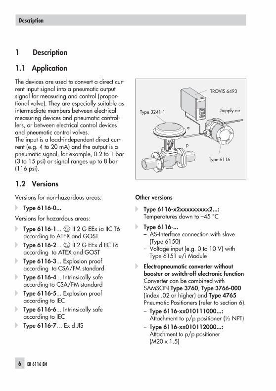
The devices are used to convert a direct cur-rent input signal into a pneumatic outputsignal for measuring and control (propor-tional valve). They are especially suitable asintermediate members between electricalmeasuring devices and pneumatic control-lers, or between electrical control devicesand pneumatic control valves.The input is a load-independent direct cur-rent (e.g. 4 to 20 mA) and the output is apneumatic signal, for example, 0.2 to 1 bar(3 to 15 psi) or signal ranges up to 8 bar(116 psi).
1.2 Versions
Versions for non-hazardous areas:
� Type 6116-0...
Versions for hazardous areas:
� Type 6116-1... II 2 G EEx ia IIC T6according to ATEX and GOST
� Type 6116-2... II 2 G EEx d IIC T6according to ATEX and GOST
� Type 6116-3... Explosion proofaccording to CSA/FM standard
� Type 6116-4... Intrinsically safeaccording to CSA/FM standard
� Type 6116-5... Explosion proofaccording to IEC
� Type 6116-6... Intrinsically safeaccording to IEC
� Type 6116-7… Ex d JIS
Other versions
� Type 6116-x2xxxxxxxxx2...:Temperatures down to –45 °C
� Type 6116-...– AS-Interface connection with slave
(Type 6150)– Voltage input (e.g. 0 to 10 V) with
Type 6151 u/i Module
� Electropneumatic converter withoutbooster or switch-off electronic functionConverter can be combined withSAMSON Type 3760, Type 3766-000(index .02 or higher) and Type 4765Pneumatic Positioners (refer to section 6).– Type 6116-xx010111000...:
Attachment to p/p positioner (½ NPT)– Type 6116-xx010112000...:
Attachment to p/p positioner(M20 x 1.5)
6 EB 6116 EN
Description
Type 3241-1
p
TROVIS 6493
e
Type 6116
Supply air
1.3 Technical data
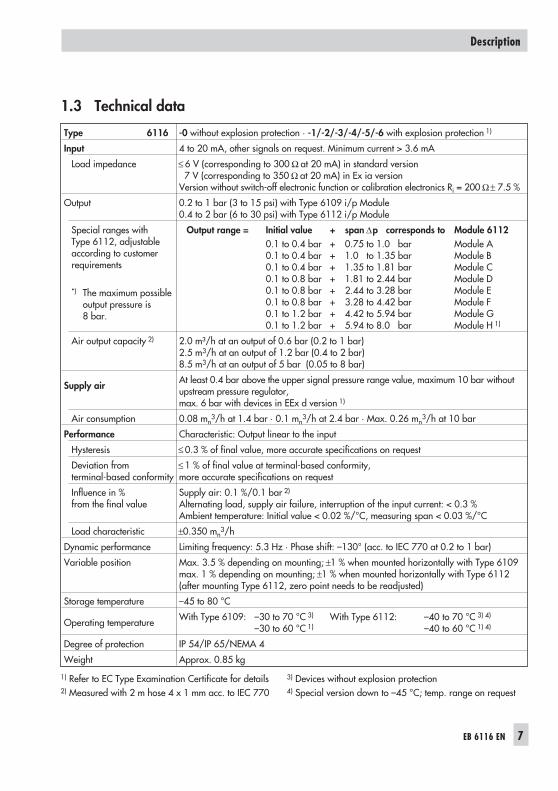
Type 6116 -0 without explosion protection · -1/-2/-3/-4/-5/-6 with explosion protection 1)
Input 4 to 20 mA, other signals on request. Minimum current > 3.6 mA
Load impedance ≤ 6 V (corresponding to 300 Ω at 20 mA) in standard version7 V (corresponding to 350 Ω at 20 mA) in Ex ia version
Version without switch-off electronic function or calibration electronics Ri = 200 Ω± 7.5 %
Output 0.2 to 1 bar (3 to 15 psi) with Type 6109 i/p Module0.4 to 2 bar (6 to 30 psi) with Type 6112 i/p Module
Special ranges withType 6112, adjustableaccording to customerrequirements
*) The maximum possibleoutput pressure is8 bar.
Output range = Initial value + span Δp corresponds to Module 61120.1 to 0.4 bar + 0.75 to 1.0 bar Module A0.1 to 0.4 bar + 1.0 to 1.35 bar Module B0.1 to 0.4 bar + 1.35 to 1.81 bar Module C0.1 to 0.8 bar + 1.81 to 2.44 bar Module D0.1 to 0.8 bar + 2.44 to 3.28 bar Module E0.1 to 0.8 bar + 3.28 to 4.42 bar Module F0.1 to 1.2 bar + 4.42 to 5.94 bar Module G0.1 to 1.2 bar + 5.94 to 8.0 bar Module H 1)
Air output capacity 2) 2.0 m³/h at an output of 0.6 bar (0.2 to 1 bar)2.5 m3/h at an output of 1.2 bar (0.4 to 2 bar)8.5 m3/h at an output of 5 bar (0.05 to 8 bar)
Supply air At least 0.4 bar above the upper signal pressure range value, maximum 10 bar withoutupstream pressure regulator,max. 6 bar with devices in EEx d version 1)
Air consumption 0.08 mn3/h at 1.4 bar · 0.1 mn
3/h at 2.4 bar · Max. 0.26 mn3/h at 10 bar
Performance Characteristic: Output linear to the input
Hysteresis ≤ 0.3 % of final value, more accurate specifications on request
Deviation fromterminal-based conformity
≤ 1 % of final value at terminal-based conformity,more accurate specifications on request
Influence in %from the final value
Supply air: 0.1 %/0.1 bar 2)
Alternating load, supply air failure, interruption of the input current: < 0.3 %Ambient temperature: Initial value < 0.02 %/°C, measuring span < 0.03 %/°C
Load characteristic ±0.350 mn3/h
Dynamic performance Limiting frequency: 5.3 Hz · Phase shift: –130° (acc. to IEC 770 at 0.2 to 1 bar)
Variable position Max. 3.5 % depending on mounting; ±1 % when mounted horizontally with Type 6109max. 1 % depending on mounting; ±1 % when mounted horizontally with Type 6112(after mounting Type 6112, zero point needs to be readjusted)
Storage temperature –45 to 80 °C
Operating temperature With Type 6109: –30 to 70 °C 3) With Type 6112: –40 to 70 °C 3) 4)
–30 to 60 °C 1) –40 to 60 °C 1) 4)
Degree of protection IP 54/IP 65/NEMA 4
Weight Approx. 0.85 kg
1) Refer to EC Type Examination Certificate for details 3) Devices without explosion protection2) Measured with 2 m hose 4 x 1 mm acc. to IEC 770 4) Special version down to –45 °C; temp. range on request
EB 6116 EN 7
Description
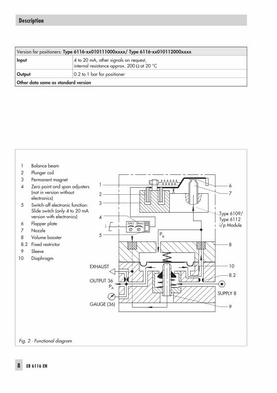
Version for positioners: Type 6116-xx010111000xxxx/ Type 6116-xx010112000xxxx
Input 4 to 20 mA, other signals on request,internal resistance approx. 200 Ω at 20 °C
Output 0.2 to 1 bar for positioner
Other data same as standard version
8 EB 6116 EN
Description
Type 6109/Type 6112i/p Module
1 Balance beam2 Plunger coil3 Permanent magnet4 Zero point and span adjusters
(not in version withoutelectronics)
5 Switch-off electronic function:Slide switch (only 4 to 20 mAversion with electronics)
6 Flapper plate7 Nozzle8 Volume booster8.2 Fixed restrictor9 Sleeve
10 Diaphragm
Fig. 2 · Functional diagram
1.4 Principle of operation
Fig. 2
The device consists of an i/p converter mod-ule and a connected volume booster.The supplied direct current i flows throughthe plunger coil (2) located in the field of apermanent magnet (3). At the balance beam(1), the force of the plunger coil, which isproportional to the current, is balancedagainst the force of the dynamic back-pres-sure. The back-pressure is produced on theflapper (6) by the air jet leaving the nozzle(7). The supply air (SUPPLY 8) flows into thelower diaphragm chamber of the booster(8); a certain amount of this air determinedby the diaphragm position flows past thesleeve (9) to the output (OUTPUT 36) of theconverter.When the input current and thus the force atthe plunger coil increases, the flapper plate(6) moves closer to the nozzle (7). Thiscauses the back pressure and the cascadepressure pK forming upstream of therestrictor (8.2) to increase. The cascadepressure increases until it is equal to the in-put current.When the cascade pressure increases, thediaphragm (10) and the sleeve (9) arepushed downwards causing the supply airto increase the output pressure pA until anew state of equilibrium is reached in the di-aphragm chambers.When the cascade pressure drops, the dia-phragm moves upwards and releases thesleeve. The output pressure pA can passthrough the sleeve to be vented (EXHAUSTport) until a new state of equilibrium isreached.
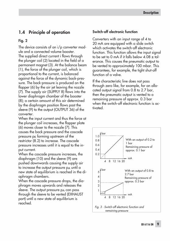
Switch-off electronic function
Converters with an input range of 4 to20 mA are equipped with a slide switchwhich activates the switch-off electronicfunction. This function allows the input signalto be set to 0 mA if it falls below 4.08 ± tol-erance. This causes the pneumatic output tobe vented to approximately 100 mbar. Thisguarantees, for example, the tight shut-offfunction of a valve.
If the characteristic line does not passthrough zero like, for example, for an allo-cated output signal from 0.8 to 2.7 bar,then the pneumatic output is vented to aremaining pressure of approx. 0.3 barwhen the switch-off electronic function is ac-tivated.
EB 6116 EN 9
Description
4 8 12 16 20mA
4 8 12 16 20mA
0.2
0.4
0.6
0.81.0
1
23
4
5
bar
bar
Fig. 3 · Switch-off electronic function andremaining pressure
With an output of 0.2 to1 barRemaining pressure ofapprox. 0.1 bar
With an output of 0.8 to2.7 barRemaining pressure ofapprox. 0.3 bar
2 Installation
2.1 Mounting position
The converter is to be mounted horizontallywith the pressure gauge (or stopper plug)facing upwards. If a different mounting po-sition is used, the zero point must be read-justed as described in section 3.1.For devices with a degree of protectionIP 54, it is essential to direct the EXHAUSTport for venting downwards to face thefloor.
2.2 Mounting
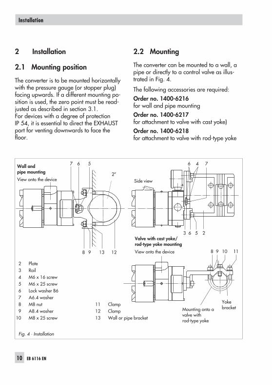
The converter can be mounted to a wall, apipe or directly to a control valve as illus-trated in Fig. 4.
The following accessories are required:Order no. 1400-6216for wall and pipe mountingOrder no. 1400-6217for attachment to valve with cast yoke)Order no. 1400-6218for attachment to valve with rod-type yoke
10 EB 6116 EN
Installation
Fig. 4 · Installation
2 Plate3 Rail4 M6 x 16 screw5 M6 x 25 screw6 Lock washer B67 A6.4 washer8 M8 nut9 A8.4 washer
10 M8 x 25 screw
11 Clamp12 Clamp13 Wall or pipe bracket
Wall andpipe mounting
View onto the device Side view
Valve with cast yoke/rod-type yoke mounting
View onto the device
Mounting onto avalve withrod-type yoke
Yokebracket
2”
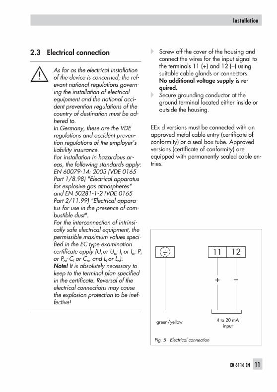
2.3 Electrical connection
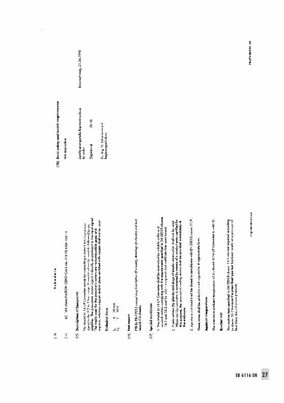
As far as the electrical installationof the device is concerned, the rel-evant national regulations govern-ing the installation of electricalequipment and the national acci-dent prevention regulations of thecountry of destination must be ad-hered to.In Germany, these are the VDEregulations and accident preven-tion regulations of the employer'sliability insurance.For installation in hazardous ar-eas, the following standards apply:EN 60079-14: 2003 (VDE 0165Part 1/8.98) "Electrical apparatusfor explosive gas atmospheres"and EN 50281-1-2 (VDE 0165Part 2/11.99) "Electrical appara-tus for use in the presence of com-bustible dust".For the interconnection of intrinsi-cally safe electrical equipment, thepermissible maximum values speci-fied in the EC type examinationcertificate apply (Ui or Uo; Ii or Io; Pior Po; Ci or Co, and Li or Lo).Note! It is absolutely necessary tokeep to the terminal plan specifiedin the certificate. Reversal of theelectrical connections may causethe explosion protection to be inef-fective!
� Screw off the cover of the housing andconnect the wires for the input signal tothe terminals 11 (+) and 12 (–) usingsuitable cable glands or connectors.No additional voltage supply is re-quired.
� Secure grounding conductor at theground terminal located either inside oroutside the housing.
EEx d versions must be connected with anapproved metal cable entry (certificate ofconformity) or a seal box tube. Approvedversions (certificate of conformity) areequipped with permanently sealed cable en-tries.
EB 6116 EN 11
Installation
Fig. 5 · Electrical connection
4 to 20 mAinput
green/yellow
2.4 Pneumatic connection
The connections for supply air (SUPPLY 8)and output air (OUTPUT 36) are designedas bore holes with either G ¼ or ¼-18 NPTthreaded connections (see page 20).Customary screw glands for metal pipes orplastic hoses can be used.
Supply air (see technical data on page 7)
� Min. + 0.4 bar above the upper signalpressure range value
� Max. 10 barMax. 6 bar for Type 6116-2 (seepage 26)
Note!The supply air must be dry and free of oiland dust. The maintenance regulations forconnected reducing stations must be ob-served. Blow out all air connections beforeattachment.
Note!When extending the exhaust by connectinga pipe either to the exhaust angle piece ordirectly to the G or NPT connection, makesure that no water can enter at the end ofthe pipe. The pipe must have a sufficientlylarge cross-sectional area of at least28 mm² = 6 mm inside diameter.
3 Operation
3.1 Checking zero point and span
The device converts the input signal propor-tionally into the output signal.The signal ranges are specified on thenameplate.
In case of a mounting position that is nothorizontal or when the pressure gauge/stopper plug does not face upwards, zeroand span can be corrected by approx. 10 %using the electronics. To do this, proceed asfollows:
1. Screw off the cover to access the ZEROand SPAN potentiometers on the circuitboard.
2. Connect a pressure gauge (minimumaccuracy class 1) to the converter output.
3. Set the supply air to 0.4 bar above theupper range value of the output signaland apply it to the device.
4. Deactivate the switch-off electronic func-tion at the slide switch (5).
Checking the zero point
5. Set the input signal to the lower rangevalue with a suitable current source (e.g.for range 4 to 20 mA = 0.2 to 1 bar, setto 4 mA).
The output signal of the pressure gaugeshould now indicate 0.2 bar. If this is notthe case, readjust the zero point accord-ingly with the ZERO potentiometer.
12 EB 6116 EN
Operation
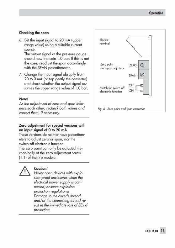
Checking the span
6. Set the input signal to 20 mA (upperrange value) using a suitable currentsource.The output signal at the pressure gaugeshould now indicate 1.0 bar. If this is notthe case, readjust the span accordinglywith the SPAN potentiometer.
7. Change the input signal abruptly from20 to 0 mA (or tap gently the converter)and check whether the output signal as-sumes the upper range value of 1.0 bar.
Note!As the adjustment of zero and span influ-ence each other, recheck both values andcorrect them, if necessary.
Zero adjustment for special versions withan input signal of 0 to 20 mA.These versions do neither have potentiom-eters to adjust zero or span, nor theswitch-off electronic function.The zero point can only be adjusted me-chanically at the zero adjustment screw(1.1) of the i/p module.
Caution!Never open devices with explo-sion-proof enclosures when theelectrical power supply is con-nected; observe explosionprotection regulations!Damage to the cover's threadand/or the connecting thread re-sult in the immediate loss of EEx dprotection.
EB 6116 EN 13
Operation
Electricterminal
Switch for switch-offelectronic function
Zero pointand span adjusters
Fig. 6 · Zero point and span correction
4 Maintenance
There are no specific maintenance measuresto be carried out.
To guarantee trouble-free operation of theconverter, make sure that the supply air isalways pure and clean.
Air filters and separators of the connectedpressure reducing station need to bechecked at regular intervals.
4.1 Cleaning the throttle
The throttle (see dimensional drawing onpage 22) is located inside the housing. Itcan be accessed from the back of the de-vice. It can be taken out after the screw plug(Ø10) has been removed.When the output signal is too small or whenthere is no output signal at all, the throttlemight be blocked. To remove all blockages,take the filter out of the throttle and clean orreplace it.
Filter Order no. 0550-0193Throttle with filter Order no. 1390-0186
In addition, the pneumatic connections havefilters with plastic rims (order no.0550-0213) which can be removed forcleaning.
5 Servicing explosion-protecteddevices
If a part of the device on which the explo-sion protection is based needs to be ser-viced, the device must not be put back intooperation until an expert has inspected it ac-cording to explosion protection require-ments, has issued a certificate stating this orgiven the device a mark of conformity.
Inspection by an expert is not required if themanufacturer performs a routine test on thedevice prior to putting it back into opera-tion. The passing of the routine test must bedocumented by attaching a mark of confor-mity to the device.
Explosion-protected components may onlybe replaced by original, checked compo-nents from the manufacturer.
Devices that have already been used outsideof hazardous areas and are intended foruse in hazardous areas in future must com-ply with the safety demands placed on re-paired devices. Prior to operation, they mustbe tested according to the specificationsstipulated for "Repairing explosion-pro-tected devices".
14 EB 6116 EN
Maintenance
6 Positioner attachment
Analog positioners with Ex d explosion pro-tection can be implemented by combiningp/p positioner with a Type 6116-2 (Ex d)Converter.In the Type 6116 Converter designed forpositioner attachment, the connection to thepositioner is used in place of the booster.
Another application involves upgrading p/ppositioners to Electro pneumatic positioners(current signal input instead of the pneu-matic signal).
Type 6116-xx010111000xxxxwith ½ NPT threaded connection and
Type 6116-xx101012000xxxxwith M20 x 1.5 threaded connection
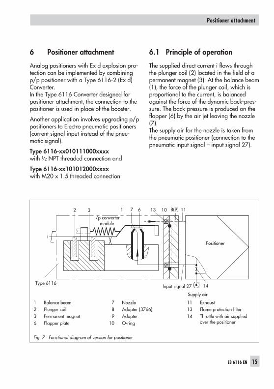
6.1 Principle of operation
The supplied direct current i flows throughthe plunger coil (2) located in the field of apermanent magnet (3). At the balance beam(1), the force of the plunger coil, which isproportional to the current, is balancedagainst the force of the dynamic back-pres-sure. The back-pressure is produced on theflapper (6) by the air jet leaving the nozzle(7).The supply air for the nozzle is taken fromthe pneumatic positioner (connection to thepneumatic input signal – input signal 27).
EB 6116 EN 15
Positioner attachment
Fig. 7 · Functional diagram of version for positioner
i/p convertermodule
1 Balance beam2 Plunger coil3 Permanent magnet6 Flapper plate
7 Nozzle8 Adapter (3766)9 Adapter
10 O-ring
11 Exhaust13 Flame protection filter14 Throttle with air supplied
over the positioner
Input signal 27
Supply air
Type 6116
Positioner
6.2 Installation
The following mounting accessories are re-quired for attachment to a positioner:
Type 3766-000 Positioner(model index .02 and higher)
Direct attachment to the positioner acc. toFig. 8 (for positioner with M20 x 1.5 electri-cal connection): Order no. 1400-6227, forolder positioner models with PG 13.5:Order no. 1400-6222
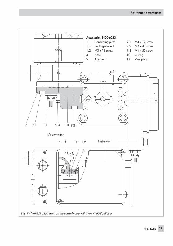
Type 4765 PositionerNAMUR attachment to the yoke of a controlvalve acc. to Fig. 9: Order no. 1400-6223
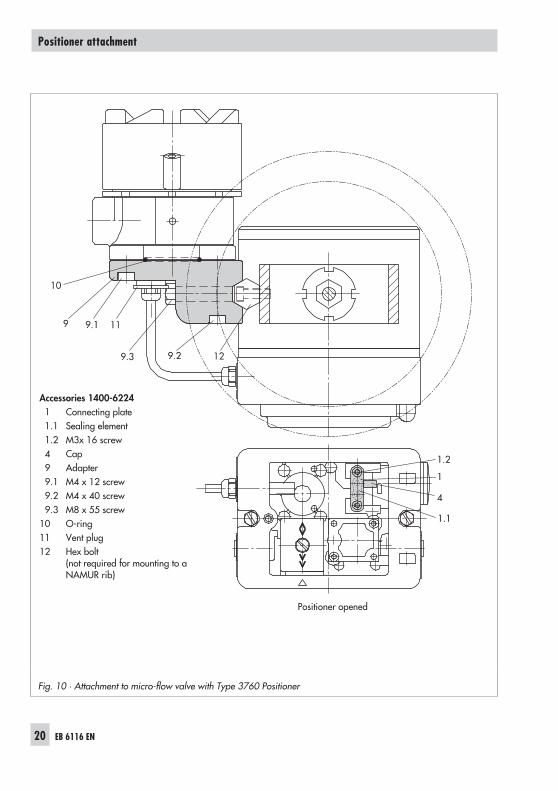
Type 3760 PositionerAttachment to the yoke of the Type 3510Micro-flow Valve according to Fig. 10 or tothe NAMUR rib: Order no. 1400-6224
6.2.1Mounting position of theconverter
The converter is to be mounted horizontallyusing the adapter with the cable entry fac-ing sideways away from the positioner orfacing away from the control valve.
Make sure the O-ring (10) to seal the con-verter housing is inserted correctly.
6.3 Electrical connection
Connect as described in section 2.3 andFig. 5.
6.4 Pneumatic connection
Note!Generally, the pneumatic connection of thei/p converter is established by connecting itto the pneumatic input of the positioner.
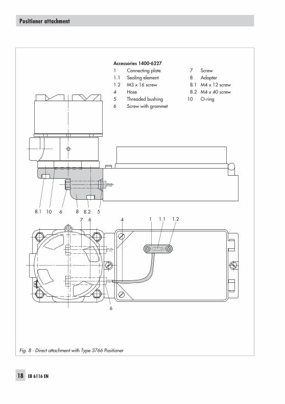
� If attached directly to the Type 3766-000Positioner (Fig. 8), the converter is con-nected via the bored screw with grommet(6) and the threaded bushing (5). Thesecond screw (7) is used to vent the con-verter over the positioner housing. Beforeattaching the adapter (8) to thepositioner, the M20 plug and the con-necting nipple (input signal) must be re-moved.
� For Types 4765 and 3760 Positioners(Fig. 9 and 10), the 1
8 NPT threaded con-nection of the adapter (9) needs to be fit-ted with an appropriate cable gland andmust be connected to the input connec-tion (input signal 27) of the positionerwith a pipe or hose. Try to keep the con-nection as short and small as possible,e.g. 6 x 1 cross section.The second bore (G ¼) serves as ventand needs to be equipped with the ventplug (11) included in the accessories.
� For all positioners, the connecting plate(1) must be removed from the bottom ofthe housing together with the sealing ele-ment (1.1) and replaced with the partsdelivered as accessories. Make sure thatthe sealing element is positioned cor-rectly. The filter must be located in frontof the throttle belong to the connectingplate.
16 EB 6116 EN
Positioner attachment
For Types 4765 and 3766, attach the sil-icone hose (4). For Type 3760, put onthe cap (4) included in the accessories.
� Refer to the mounting and operating in-structions of the corresponding positionerconcerning the connections for supply air(SUPPLY 8) and output (OUTPUT 36).
6.5 Operation
Any adjustments to assign the travel of thecontrol valve to the electric input signal mustbe made at the positioner separately fromthe converter module. The necessary stepsare described in the corresponding moun-ting and operating instructions.
EB 6116 EN 17
Positioner attachment
18 EB 6116 EN
Positioner attachment
Fig. 8 · Direct attachment with Type 3766 Positioner
Accessories 1400-62271 Connecting plate1.1 Sealing element1.2 M3 x 16 screw4 Hose5 Threaded bushing6 Screw with grommet
7 Screw8 Adapter8.1 M4 x 12 screw8.2 M4 x 40 screw
10 O-ring
EB 6116 EN 19
Positioner attachment
Fig. 9 · NAMUR attachment on the control valve with Type 4765 Positioner
Accessories 1400-62231 Connecting plate1.1 Sealing element1.2 M3 x 16 screw4 Hose9 Adapter
9.1 M4 x 12 screw9.2 M4 x 40 screw9.3 M4 x 55 screw10 O-ring11 Vent plug
Positioner
i/p converter
20 EB 6116 EN
Positioner attachment
Accessories 1400-62241 Connecting plate1.1 Sealing element1.2 M3x 16 screw4 Cap9 Adapter9.1 M4 x 12 screw9.2 M4 x 40 screw9.3 M8 x 55 screw
10 O-ring11 Vent plug12 Hex bolt
(not required for mounting to aNAMUR rib)
Fig. 10 · Attachment to micro-flow valve with Type 3760 Positioner
Positioner opened
7 Troubleshooting
Troubleshooting
EB 6116 EN 21
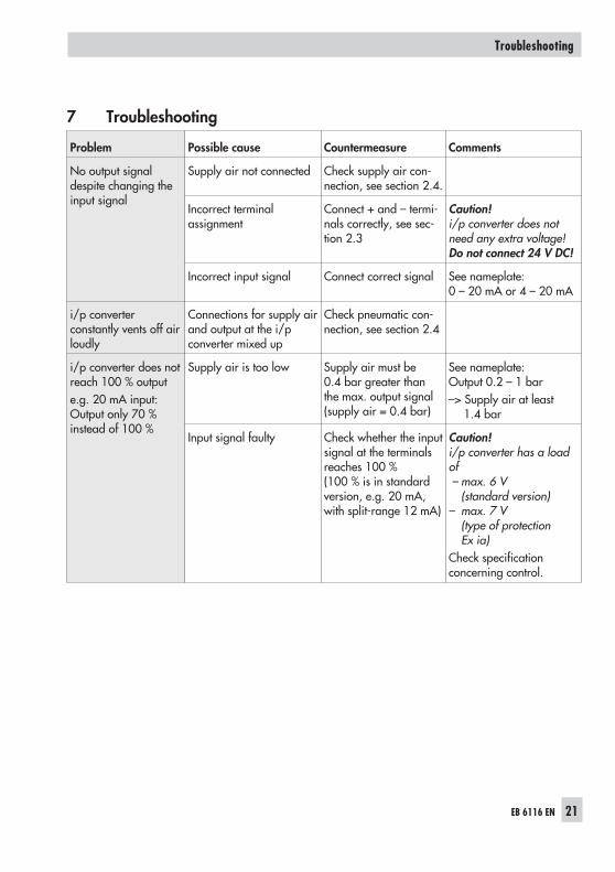
Problem Possible cause Countermeasure Comments
No output signaldespite changing theinput signal
Supply air not connected Check supply air con-nection, see section 2.4.
Incorrect terminalassignment
Connect + and – termi-nals correctly, see sec-tion 2.3
Caution!i/p converter does notneed any extra voltage!Do not connect 24 V DC!
Incorrect input signal Connect correct signal See nameplate:0 – 20 mA or 4 – 20 mA
i/p converterconstantly vents off airloudly
Connections for supply airand output at the i/pconverter mixed up
Check pneumatic con-nection, see section 2.4
i/p converter does notreach 100 % outpute.g. 20 mA input:Output only 70 %instead of 100 %
Supply air is too low Supply air must be0.4 bar greater thanthe max. output signal(supply air = 0.4 bar)
See nameplate:Output 0.2 – 1 bar–> Supply air at least
1.4 bar
Input signal faulty Check whether the inputsignal at the terminalsreaches 100 %(100 % is in standardversion, e.g. 20 mA,with split-range 12 mA)
Caution!i/p converter has a loadof– max. 6 V
(standard version)– max. 7 V
(type of protectionEx ia)
Check specificationconcerning control.
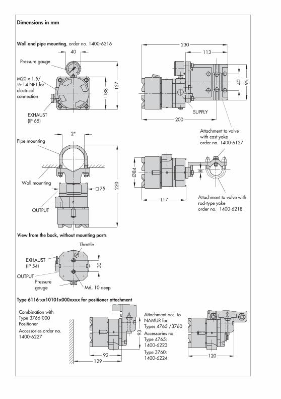
Dimensions in mm
Combination withType 3766-000PositionerAccessories order no.1400-6227
Attachment acc. toNAMUR forTypes 4765 /3760Accessories no.Type 4765:1400-6223Type 3760:1400-6224
Wall and pipe mounting, order no. 1400-6216
M20 x 1.5/½-14 NPT forelectricalconnection
EXHAUST(IP 65)
Pressure gauge
Pipe mounting
Wall mounting
Type 6116-xx10101x000xxxx for positioner attachment
View from the back, without mounting parts
EXHAUST(IP 54)
Pressuregauge M6, 10 deep
Throttle
Attachment to valvewith cast yokeorder no. 1400-6127
Attachment to valve withrod-type yokeorder no. 1400-6218OUTPUT
OUTPUT
SUPPLY
EB 6116 EN 23
24 EB 6116 EN
EB 6116 EN 25
26 EB 6116 EN
EB 6116 EN 27
28 EB 6116 EN
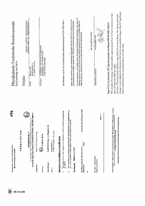
Type
6116
i/p
Conv
erte
r,EC
Type
Exam
inat
ion
Cert
ifica
tePT
B98
ATE
X10
24X
PTB
cons
ider
sth
ech
ange
inth
epe
rmis
sibl
esu
pply
pres
sure
from
2.5
bar
tom
axim
um6
bar
does
noth
ave
any
effe
cton
safe
ty.
How
ever
,PTB
reco
mm
ends
addi
nga
copy
ofth
isfa
xto
ever
yde
vice
.The
abov
em
entio
ned
chan
geis
tobe
adde
dw
ithre
fere
nce
toth
isfa
xfo
ran
ypo
ssib
lech
ange
toth
eEC
Type
Exam
i-na
tion
Cer
tific
ate
for
the
asso
ciat
edde
vice
ata
late
rda
te.
EB 6116 EN 29
��������������
�� �������������������������������
����������������������������
�
������������������� ���� ������ ������������� ��������� ��������������
���������������� ������������� ��������������������� ����������������������
���������
��������������������
�� !����
��� ��
���
"�� "����
��
#� �
��$����� ����
����
������
���
� ��
����
� �� !��
�
%
�� !����&��� ����%��� ��
��&"
��
%"
�� "���' ���
�
�
(�
����#
�� �(#
� �
�����)����*�� �������� �� �� ����� ������������������ ����
�������� ��
+����������� ��
,� ��
!��
-���
!��
-���
��� �����������
������
������
����
��
�����.������������������������������������� �������������������������
�������������������������������������
����� ��� ������
"� ������������������� ��� � ��$�
���
���
� �
�!"
�
#� �!"
�$$$��!"
�
�!"
�
� ��� ���������������������������������������������� � /��������������������
���*�� �������� ���� �������������
+�������0'������12���3
����4+������ �
������'5 �����1,1�16
�������'5 ����+1785'��������
9�����
���
��������������������������������������� �������������������
����������������� ����� �������������!����"����#������
�� !���$ ���� ��
��$"�� "����
$ ������%��
�
� ���#�������������������������
&��
��������������������������������������� �������������������
����������������� ����� ���������������� ���������
!�������������������������&�
'��
(�����������������������������������������������������)������
*��
+������������������������ ��,-����#����������������������
� �
��������������
�� �������������������������������
����������������������������
�
����������
�������
���� ����
��
�� ����
��
� � � � � � � � � � � � � � ���������������������� ������������
� ���������������������������������������������
����������� �!!����� �"� � ������!���������������!�������!������������!���#�������
����������� �!!����������������� ����!�����������������!���#�����$�
� ��������������$%�"���&���� ���������������������'�������(��'�)����%&%�*�%&+,�#��
����%&%�*�%&%�#�
�������������������� ���
�!��"���
������
"�����#���$%�&'�(��!)���'�*'� '���
��+)��,���"��!
���
"������#���$%�&'�(��!)��'��-
�('� "��������
�������������
���������
���
�� ����
��.��$%�&/�
�� ����
�
�������
��-��������� �"� � ������!�����������������!���#�����������$��
� $�-��������������������'��� ���������������������'�������(��'�
�)����%&%%&+,�#������%&%%&%�#�
�����������
�� �����������
����
����
������ ����
����
������
����
�����
������
�����
�������
�������������
������������������
�����������
�� �����������
����
����
������� �������
����
������
������
��� ��������
� �������
���������� ��
�� ��!������
30 EB 6116 EN
��������������
�� �������������������������������
����������������������������
�
���
��
����
�
���
�
����
���
������
���
���
���
���
���
���
���
�
��
���
��
���
����
���
����������
�������
���� ������
�� ������
� � � � � � � � � � � � � � ���������
��
����
��
���
� !"
���
��
�����
�� #�
���
�
����
��
���
��
���
����
$�
!�#%
���
��
���
�$�
���&
��
���
����
��
���
'��
��
���
����
����
�&���
���
��(�
��
����
�(��
(�����
���)
��
���
�$�
���&
��
���
����
��
���
����
��
���
����
����
���
�&��(
��(�
����
���)
��
��*
�� �
��
���
��
���
�*+
�'��
����
���
���
�(�
�
�����
((�
���
���
���
���
��
�,�
���
+�
+�-
�+�
./
�)��
���
�+
�+
�-�+
��
+�)
�
���������������� �!����"��#�$�%�����
#�����&����������'&�(��"����&�)&� &���
�����*+�
#����������������'&�(��"����,�(&� #��������
����������������������
���
�� ������-���.�'/�
�� �����
��%����
���
�$�
���&
���
�'�
��
���
��
���
����
�&��(
��(�
����
���)
��
���
��
��*
��*
���
��
��
��
����
�
���
����
�����
�(�
�
�����
((�
���
���
���
���
��
��
,�
���
+�
+�+
�.
/�)
��
���
+�
+�+
��
+�)
�.
���
)&���
���
����
��
&�
��
���
��((
���
�
(���
��&
��&
��,
����
�
�0�
(���
(���
��
��%
,# !
,$"%
�1+
�
�����������
�� �����������
����
����
�����
�� �����
����
������
����
�����
������
�����
������
�������������
������������������
�����������
�� �����������
����
����
������� �������
����
������
������
��� ��������
� �������
���������� ��
�� ��!������
��������������
�� �������������������������������
����������������������������
�
������������������� ���� ������� ��������� ��������� ����
����������
���������
���
����
����
����
�����
��
�����
����
��
�����
��� �
��������
�����
���
�����
����
�����
��������������������
�� �� �����
���
� ��
���
� �� ����
!�
"� �
#�$����� ����
����
������
���
��
����
� %������
��
� ���� �� �&�
��� �����
' ���
�
� ��
�� ��
�
&�� �� ��
���
�
�
� ���&
��� ����
�����(��)��� ������ �� �� ����� ������������������ ����
#������� ��
*����������� ��
+� ��
���
,��
���
���
,��
���
#�$����� ����
������
������
��������
����
��
���
�����-���
��������
����
���
�����
����
����
���
��� �������
��
���
��������
�����
��
�����
����
���������������������
�����
����� ��� ������
� �
������������������ ��� � ��$�
���
���
���
����
������������������
����
� ��� ��������������������������������������
�������� � .��������������������
�)��� ������ ���� �������������
!�����/0���1/2*�����!�3
%*245
!�����/��/���/6��������/7 ����2/+/!/6*/�879
%�����
���
����
�����
����
���������������������
����� �
�����
���
���
���
����
����
����
�
��������
�
����
!���
�����
��������
�"��
��
!���
���
#� ���$����
% �&�
�
��&�
��%'����'����
% �(���
�)��
�
� ��
�!������������
�����
�������
� *��
����
�����
����
���������������������
����� �
�����
���
���
���
����
����
����
�
��������
�����
!������
����
�����
��
�������
������������
������
��������*
�
+��
&������������������
�����
���
�������,
���������������
�(���-
,.&/,�'-0
1
��-
,.&/&.-2
'�
*�1
3�1
�

EB 6116 EN 31

SAMSON AG · MESS- UND REGELTECHNIKWeismüllerstraße 3 · 60314 Frankfurt am Main · GermanyPhone: +49 69 4009-0 · Fax: +49 69 4009-1507Internet: http://www.samson.de EB 6116 EN 20
07-1
0