Embed Size (px)
Citation preview
1 V1 08 March 2013 EMR
Motorsport South Africa
SOUTH AFRICAN KARTING COMMISSION
HOMOLOGATION SCHEDULE MAXTERINO MX-60
Version 3 2014-01-01
MSA Ref.
Manufacturer MAXTER S.R.L.
Distributor Ed Murray Racing cc
Model Maxterino
Period of homologation 1 December 2009 – 31 December 2015
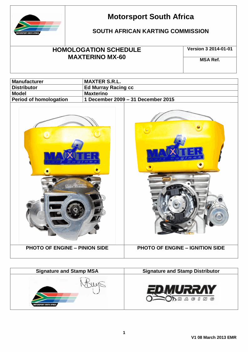
PHOTO OF ENGINE – PINION SIDE PHOTO OF ENGINE – IGNITION SIDE
Signature and Stamp MSA Signature and Stamp Distributor
2 V1 08 March 2013 EMR
TECHNICAL INFORMATION
A
DESCRIPTION
Tolerance
Maximum Capacity 60cc
Stroke 42,1mm Bore 43mm +/- 0,10 mm.
Induction Piston Port
Cooling Free Air Carburator Mini Kart Del’Orto PHBG18BS Diameter 18,00mm. No
modifications at all. Needle marked W23 only. Only adjustments permitted are: main jet size 68, 69, 70, 71, 72 and 73 needle clip position and idle air screw. Original floats: 4g, Idle jet: 50, Emulsion tube: 262AU and spring type needle, Starting jet: 60;
Number of Transfer Ports 2
Ignition and timing Original Seletra analogue ignition only set that the marks correspond at 0.70mm before TDC
Maximum
Width of Exhaust Port 28,00 mm. +/- 0,10 mm.
Width of Inlet Port 26,00 mm. +/- 0,10 mm.
Overall Piston Height 49 mm. +/- 0,8 mm
Mass of Piston Mass 61 g including ring. Only original Maxter spare parts with no modification. Material may be removed from the lower edge of the skirt only to achieve correct inlet duration. NB. Minimal corner break to remove sharp edge only as per original part.
(+/- 10% of the total)
Total weight of crankshaft including the conrod excluding the piston
1362 g. (+/- 3% of the total)
Shape of combustion chamber Hemisphere as per MSA gauge, no polishing. MSA gauge must fit with no clearance on sealing surface. Spark plug leg of gauge may not protrude above sealing face of spark plug.
Squish Clearance 0.6 mm. With 1.6 mm. resin core solder at smallest point
Minimum
Spark Plug NGK BR10EG Pinion Z11
Rear Sprocket 80 to 86 tooth all included
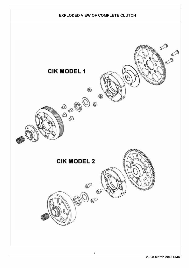
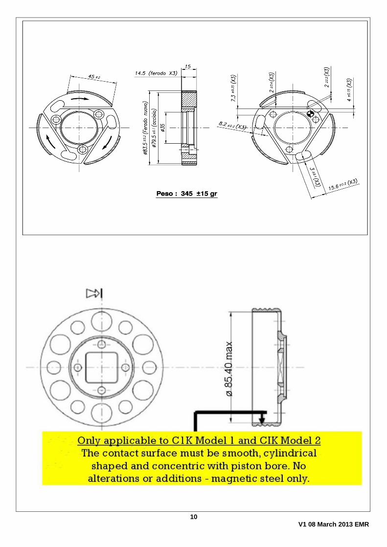
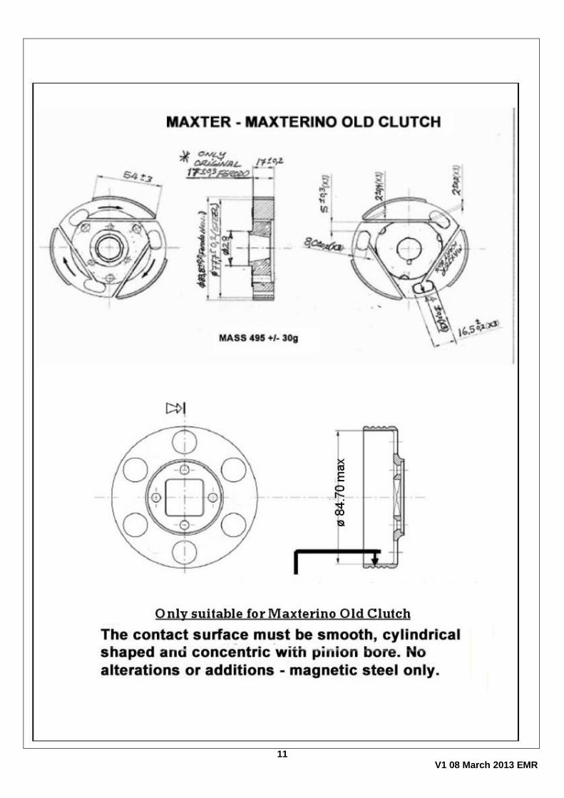
Clutch Original parts only, no modifications, as per drawing. In the interests of standardisation and to ensure spare parts availability, it was decided to allow the CIK KF clutch going forward. These CIK clutch complete assemblies weigh a minimum of 800g and the inner hub 345 +/- 15g. The drum inside diameter may not exceed 85.40mm on these clutches. The earlier model original Maxter clutch is also permitted until further notice NB maximum inside diameter of these drums is 84.70mm. All of the original clutches offer exactly the same performance.
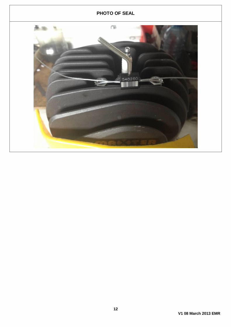
Seal Registered serial numbered seal, as per photo. Sealed through two cylinder nuts
3 V1 08 March 2013 EMR
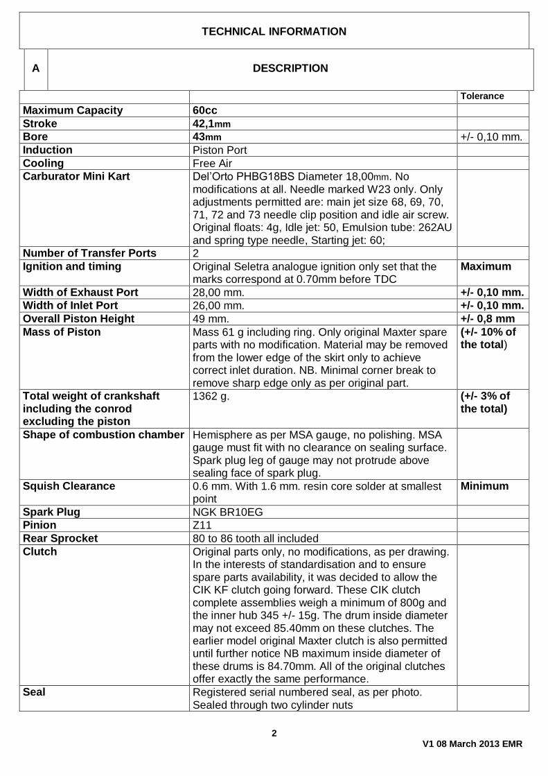
B
PORT TIMING
(measured with 0.20 mm. feeler gauge 10 mm. wide)
Tolleranze
Inlet 144° Maximum
Exhaust 156° Maximum
C
Material
Cylinder Alluminium casting with CNC machined cast iron liner No grinding or polishing allowed
DEVELOPMENT OF CYLINDER
Airbox and filter Only original type as supplied complete with functioning air filter is permitted. It is permitted to drill a single 8.0mm maximum diameter hole on the lower side near the front to drain water in the event of rain.
4 V1 08 March 2013 EMR
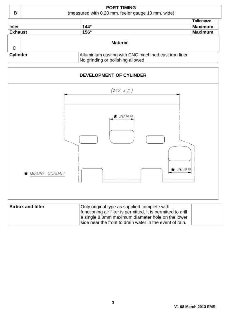
SECTION AND PLAN OF COMBUSTION CHAMBER
HEAD GAUGE MSA MX-60 MUST FIT WITH NO LIGHT ON SEALING FACE
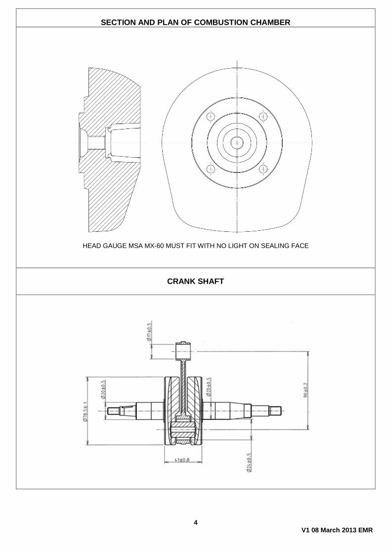
CRANK SHAFT
5 V1 08 March 2013 EMR
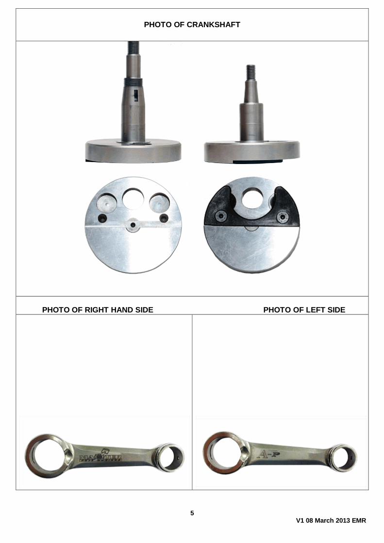
PHOTO OF CRANKSHAFT
PHOTO OF RIGHT HAND SIDE PHOTO OF LEFT SIDE
6 V1 08 March 2013 EMR
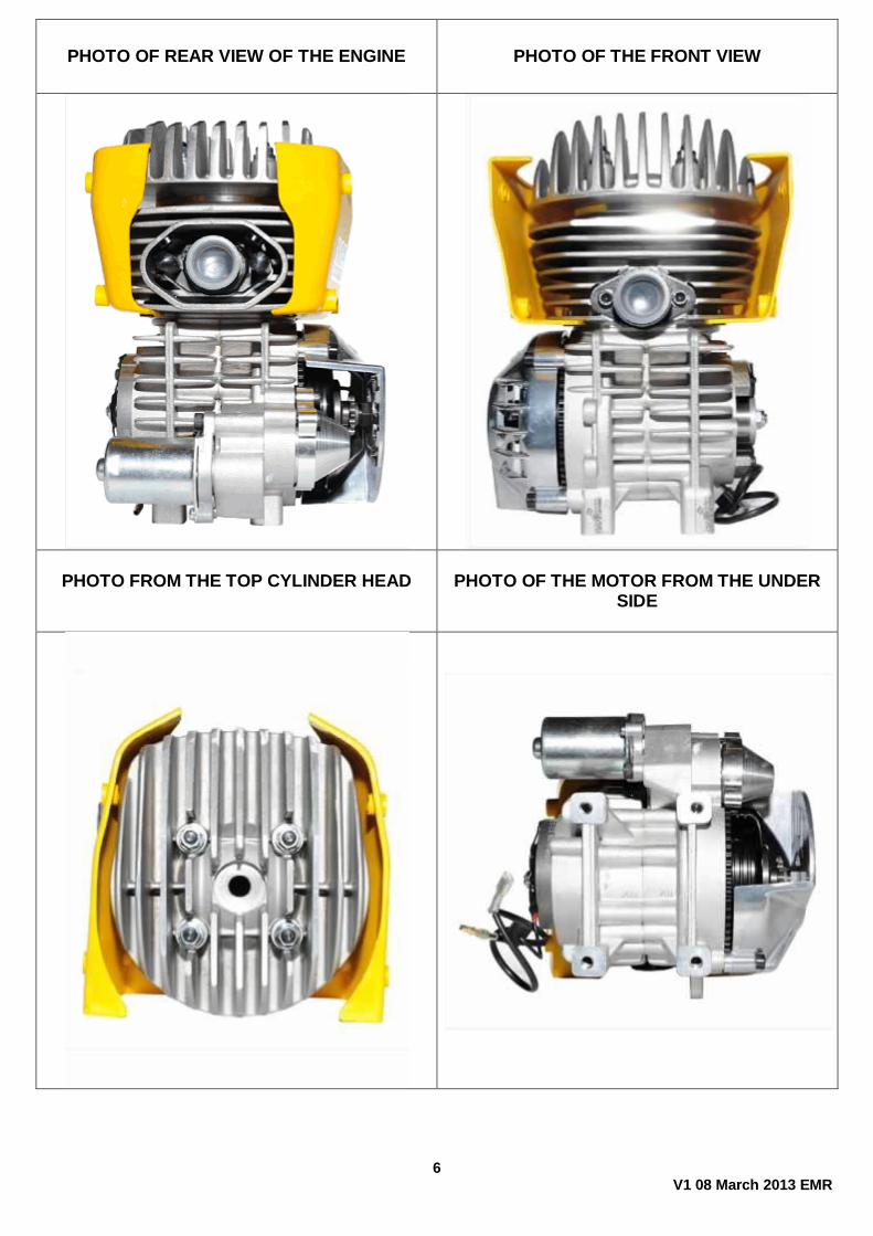
PHOTO OF REAR VIEW OF THE ENGINE PHOTO OF THE FRONT VIEW
PHOTO FROM THE TOP CYLINDER HEAD
PHOTO OF THE MOTOR FROM THE UNDER
SIDE
7 V1 08 March 2013 EMR
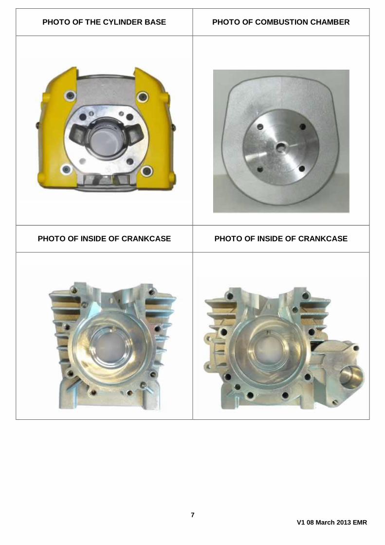
PHOTO OF THE CYLINDER BASE
PHOTO OF COMBUSTION CHAMBER
PHOTO OF INSIDE OF CRANKCASE
PHOTO OF INSIDE OF CRANKCASE
8 V1 08 March 2013 EMR
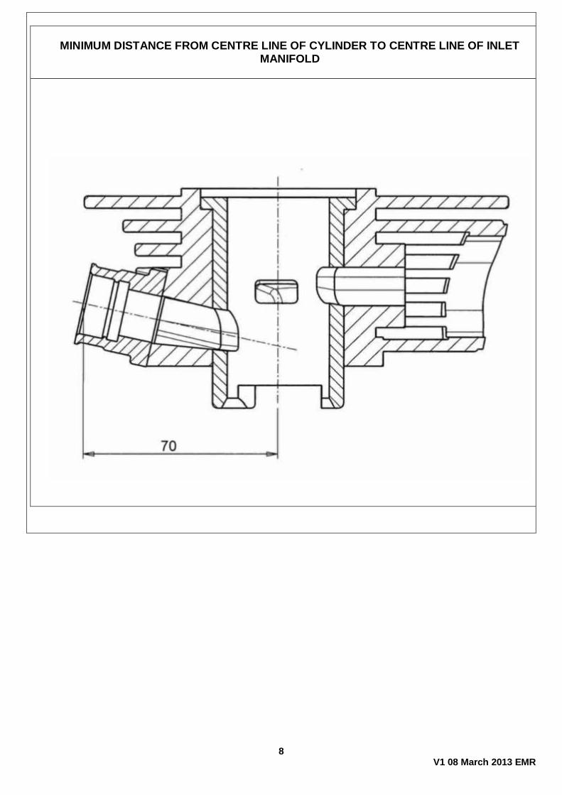
MINIMUM DISTANCE FROM CENTRE LINE OF CYLINDER TO CENTRE LINE OF INLET
MANIFOLD
9 V1 08 March 2013 EMR
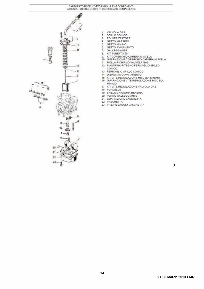
EXPLODED VIEW OF COMPLETE CLUTCH
10 V1 08 March 2013 EMR
11 V1 08 March 2013 EMR
12 V1 08 March 2013 EMR
PHOTO OF SEAL
13 V1 08 March 2013 EMR
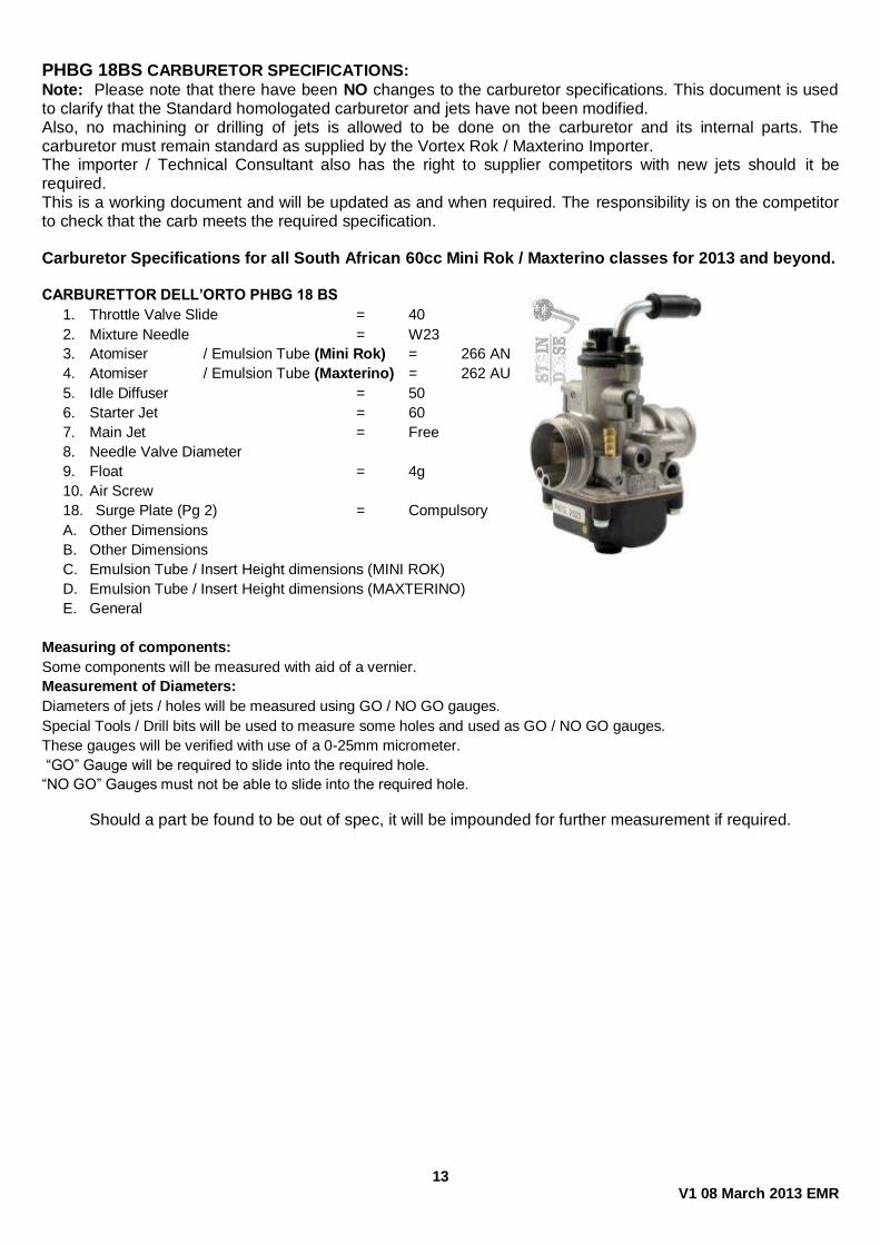
PHBG 18BS CARBURETOR SPECIFICATIONS:
Note: Please note that there have been NO changes to the carburetor specifications. This document is used to clarify that the Standard homologated carburetor and jets have not been modified. Also, no machining or drilling of jets is allowed to be done on the carburetor and its internal parts. The carburetor must remain standard as supplied by the Vortex Rok / Maxterino Importer. The importer / Technical Consultant also has the right to supplier competitors with new jets should it be required. This is a working document and will be updated as and when required. The responsibility is on the competitor to check that the carb meets the required specification. Carburetor Specifications for all South African 60cc Mini Rok / Maxterino classes for 2013 and beyond. CARBURETTOR DELL’ORTO PHBG 18 BS
1. Throttle Valve Slide = 40
2. Mixture Needle = W23
3. Atomiser / Emulsion Tube (Mini Rok) = 266 AN
4. Atomiser / Emulsion Tube (Maxterino) = 262 AU
5. Idle Diffuser = 50
6. Starter Jet = 60
7. Main Jet = Free
8. Needle Valve Diameter
9. Float = 4g
10. Air Screw
18. Surge Plate (Pg 2) = Compulsory
A. Other Dimensions
B. Other Dimensions
C. Emulsion Tube / Insert Height dimensions (MINI ROK)
D. Emulsion Tube / Insert Height dimensions (MAXTERINO)
E. General
Measuring of components:
Some components will be measured with aid of a vernier.
Measurement of Diameters:
Diameters of jets / holes will be measured using GO / NO GO gauges.
Special Tools / Drill bits will be used to measure some holes and used as GO / NO GO gauges.
These gauges will be verified with use of a 0-25mm micrometer.
“GO” Gauge will be required to slide into the required hole.
“NO GO” Gauges must not be able to slide into the required hole.
Should a part be found to be out of spec, it will be impounded for further measurement if required.
14 V1 08 March 2013 EMR
0
15 V1 08 March 2013 EMR
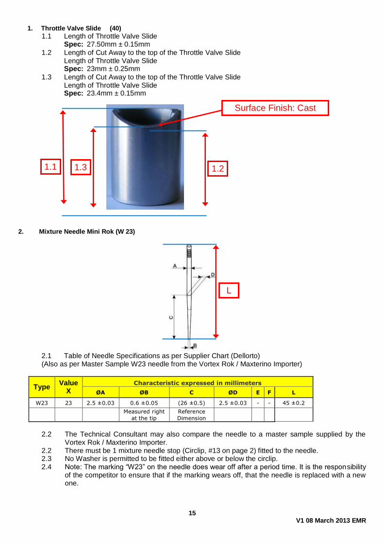
1. Throttle Valve Slide (40)
1.1 Length of Throttle Valve Slide Spec: 27.50mm ± 0.15mm
1.2 Length of Cut Away to the top of the Throttle Valve Slide Length of Throttle Valve Slide Spec: 23mm ± 0.25mm
1.3 Length of Cut Away to the top of the Throttle Valve Slide Length of Throttle Valve Slide Spec: 23.4mm ± 0.15mm
2. Mixture Needle Mini Rok (W 23)
2.1 Table of Needle Specifications as per Supplier Chart (Dellorto)
(Also as per Master Sample W23 needle from the Vortex Rok / Maxterino Importer)
Type Value
X Characteristic expressed in millimeters
ØA ØB C ØD E F L
W23 23 2.5 ±0.03 0.6 ±0.05 (26 ±0.5) 2.5 ±0.03 - - 45 ±0.2
Measured right
at the tip
Reference
Dimension
2.2 The Technical Consultant may also compare the needle to a master sample supplied by the
Vortex Rok / Maxterino Importer. 2.2 There must be 1 mixture needle stop (Circlip, #13 on page 2) fitted to the needle. 2.3 No Washer is permitted to be fitted either above or below the circlip. 2.4 Note: The marking “W23” on the needle does wear off after a period time. It is the responsibility
of the competitor to ensure that if the marking wears off, that the needle is replaced with a new one.
1.1 1.2
L
1.3
Surface Finish: Cast
16 V1 08 March 2013 EMR
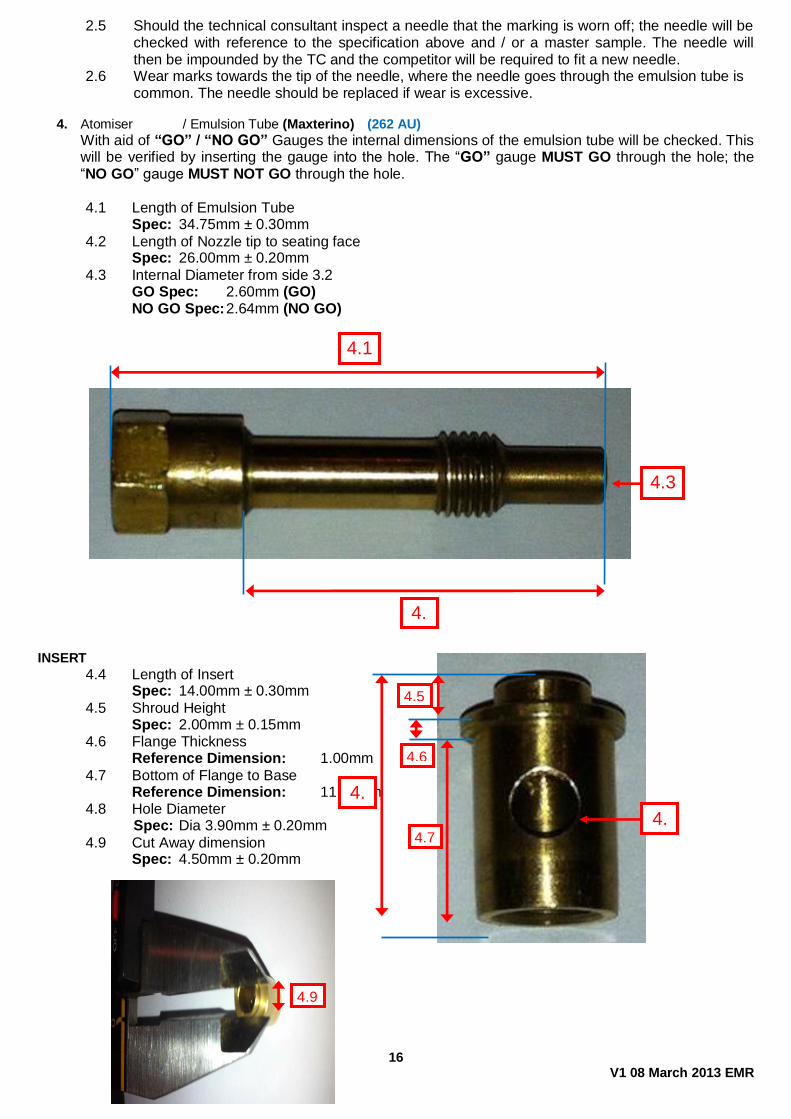
2.5 Should the technical consultant inspect a needle that the marking is worn off; the needle will be checked with reference to the specification above and / or a master sample. The needle will then be impounded by the TC and the competitor will be required to fit a new needle.
2.6 Wear marks towards the tip of the needle, where the needle goes through the emulsion tube is common. The needle should be replaced if wear is excessive.
4. Atomiser / Emulsion Tube (Maxterino) (262 AU)
With aid of “GO” / “NO GO” Gauges the internal dimensions of the emulsion tube will be checked. This will be verified by inserting the gauge into the hole. The “GO” gauge MUST GO through the hole; the “NO GO” gauge MUST NOT GO through the hole.
4.1 Length of Emulsion Tube Spec: 34.75mm ± 0.30mm
4.2 Length of Nozzle tip to seating face Spec: 26.00mm ± 0.20mm
4.3 Internal Diameter from side 3.2 GO Spec: 2.60mm (GO) NO GO Spec: 2.64mm (NO GO)
INSERT
4.4 Length of Insert Spec: 14.00mm ± 0.30mm
4.5 Shroud Height Spec: 2.00mm ± 0.15mm 4.6 Flange Thickness Reference Dimension: 1.00mm
4.7 Bottom of Flange to Base Reference Dimension: 11.00mm 4.8 Hole Diameter
Spec: Dia 3.90mm ± 0.20mm
4.9 Cut Away dimension Spec: 4.50mm ± 0.20mm
4.3
4.3
4.1
4.5
4.4
4.6
4.7
4.8
4.9

17 V1 08 March 2013 EMR
5. Idle Diffuser (50)
With aid of “GO” / “NO GO” Gauges the internal dimensions of the Idle Diffuser will be checked. This will be verified by inserting the gauge into the hole. The “GO” gauge MUST GO through the hole; the “NO GO” gauge MUST NOT GO through the hole.
5.1 Length of Idle Diffuser Spec: 9.50mm ± 0.20mm
5.2 Internal Diameter of Smallest hole inside the Idle Diffuser GO Spec: 0.5 mm (GO) NO GO Spec: 0.55 mm (NO GO)
6. Starter Jet (60)
With aid of “GO” / “NO GO” Gauges the internal dimensions of the Starter Jet will be checked. This will be verified by inserting the gauge into the hole. The “GO” gauge MUST GO through the hole; the “NO GO” gauge MUST NOT GO through the hole.
6.1 Length of Idle Jet Spec: 27.00mm ± 0.25mm 6.2 Internal Diameter of hole inside the Start Jet GO Spec: 0.60 mm (GO) NO GO Spec: 0.65 mm (NO GO)
6.3 4 holes, 90° apart GO Spec: 1.00 mm (GO)
NO GO Spec: 1.10 mm (NO GO)
5.2
5.1
6.2
6.1
6.3
18 V1 08 March 2013 EMR
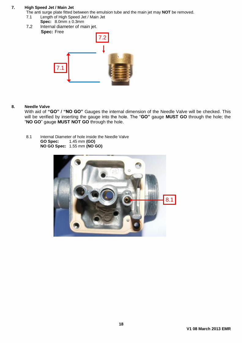
7. High Speed Jet / Main Jet The anti surge plate fitted between the emulsion tube and the main jet may NOT be removed. 7.1 Length of High Speed Jet / Main Jet Spec: 8.0mm ± 0.3mm
7.2 Internal diameter of main jet. Spec: Free
8. Needle Valve
With aid of “GO” / “NO GO” Gauges the internal dimension of the Needle Valve will be checked. This will be verified by inserting the gauge into the hole. The “GO” gauge MUST GO through the hole; the “NO GO” gauge MUST NOT GO through the hole.
8.1 Internal Diameter of hole inside the Needle Valve GO Spec: 1.45 mm (GO) NO GO Spec: 1.55 mm (NO GO)
8.1
7.1
7.2
19 V1 08 March 2013 EMR
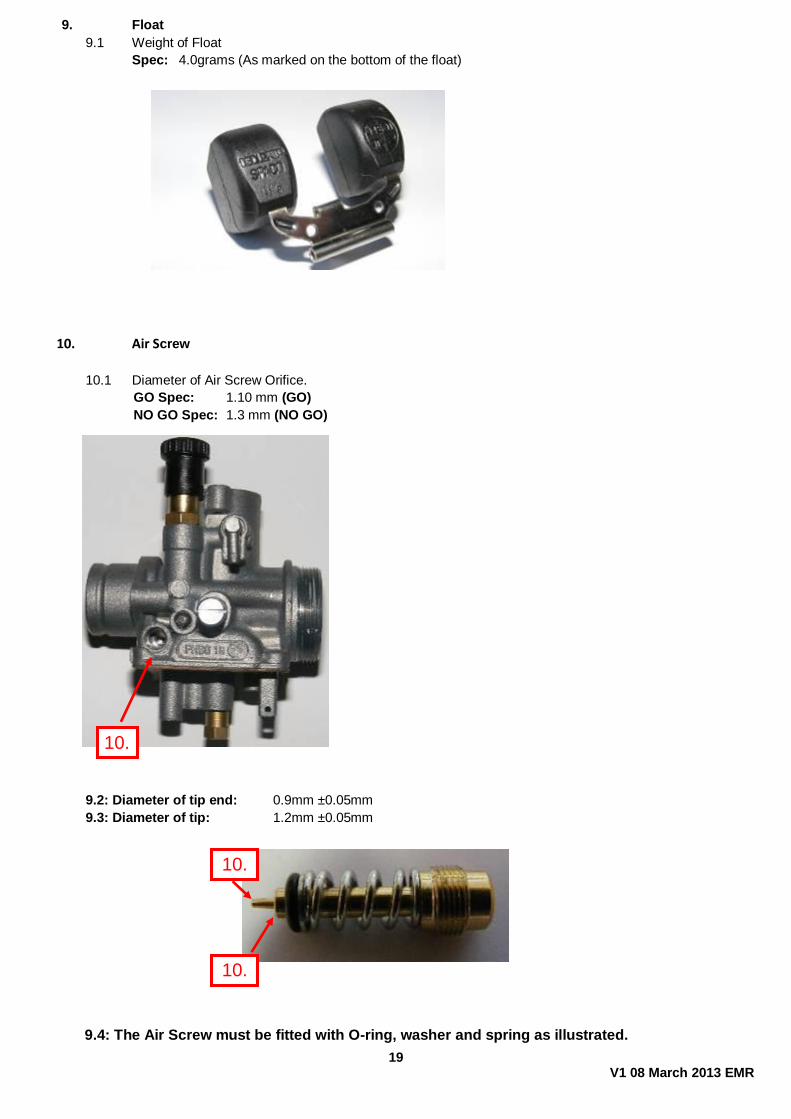
9. Float
9.1 Weight of Float
Spec: 4.0grams (As marked on the bottom of the float)
10. Air Screw
10.1 Diameter of Air Screw Orifice.
GO Spec: 1.10 mm (GO)
NO GO Spec: 1.3 mm (NO GO)
9.2: Diameter of tip end: 0.9mm ±0.05mm
9.3: Diameter of tip: 1.2mm ±0.05mm
9.4: The Air Screw must be fitted with O-ring, washer and spring as illustrated.
10.1
10.2
10.3
20 V1 08 March 2013 EMR
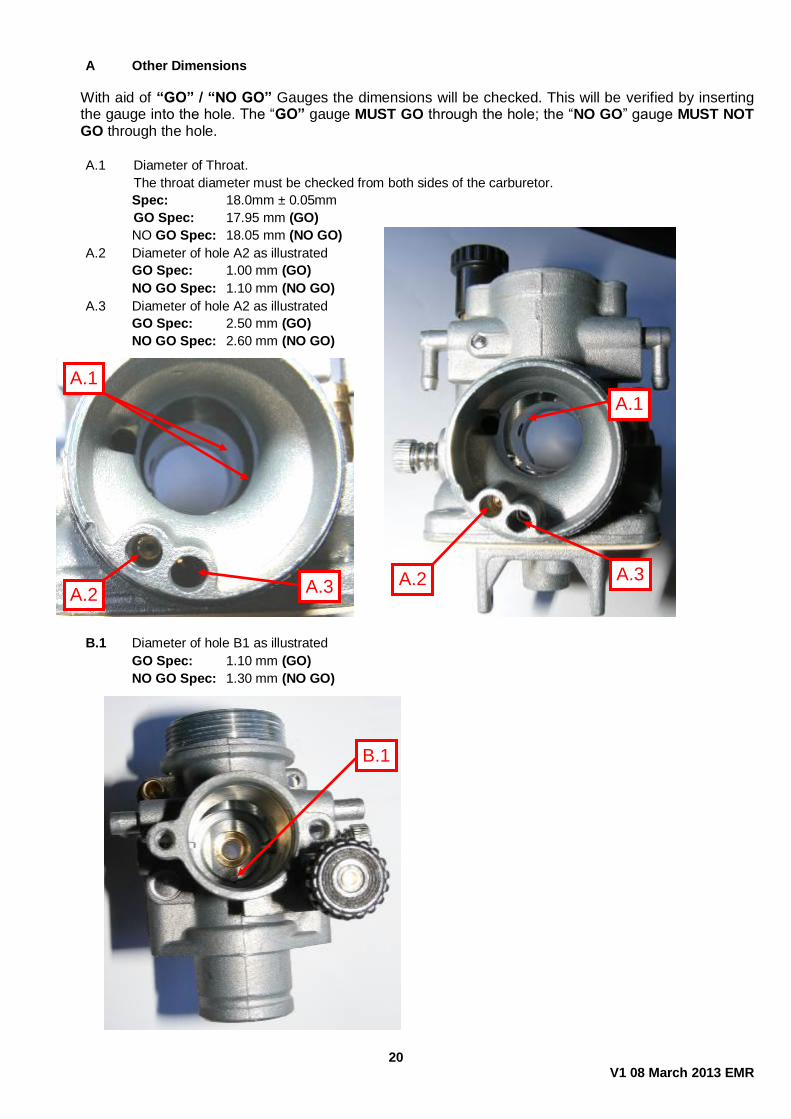
A Other Dimensions
With aid of “GO” / “NO GO” Gauges the dimensions will be checked. This will be verified by inserting the gauge into the hole. The “GO” gauge MUST GO through the hole; the “NO GO” gauge MUST NOT GO through the hole.
A.1 Diameter of Throat.
The throat diameter must be checked from both sides of the carburetor.
Spec: 18.0mm ± 0.05mm
GO Spec: 17.95 mm (GO)
NO GO Spec: 18.05 mm (NO GO)
A.2 Diameter of hole A2 as illustrated
GO Spec: 1.00 mm (GO)
NO GO Spec: 1.10 mm (NO GO)
A.3 Diameter of hole A2 as illustrated
GO Spec: 2.50 mm (GO)
NO GO Spec: 2.60 mm (NO GO)
B.1 Diameter of hole B1 as illustrated
GO Spec: 1.10 mm (GO)
NO GO Spec: 1.30 mm (NO GO)
A.2
A.1
A.3
A.1
A.2 A.3
B.1
21 V1 08 March 2013 EMR
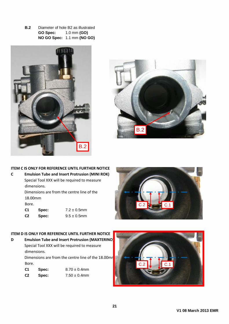
B.2 Diameter of hole B2 as illustrated
GO Spec: 1.0 mm (GO)
NO GO Spec: 1.1 mm (NO GO)
ITEM C IS ONLY FOR REFERENCE UNTIL FURTHER NOTICE
C Emulsion Tube and Insert Protrusion (MINI ROK)
Special Tool XXX will be required to measure
dimensions.
Dimensions are from the centre line of the
18.00mm
Bore.
C1 Spec: 7.2 ± 0.5mm
C2 Spec: 9.5 ± 0.5mm
ITEM D IS ONLY FOR REFERENCE UNTIL FURTHER NOTICE
D Emulsion Tube and Insert Protrusion (MAXTERINO)
Special Tool XXX will be required to measure
dimensions.
Dimensions are from the centre line of the 18.00mm
Bore.
C1 Spec: 8.70 ± 0.4mm
C2 Spec: 7.50 ± 0.4mm
B.2
B.2
C.1 C.2
C.1 C.2

22 V1 08 March 2013 EMR
E General
The over flow nipples may be turned in any direction
An overflow pipe may be fitted
Some carbs have a brass insert fitted inside the overflow tubes (Supplied from Dellorto) on the inside of the
carb. This is to prevent “Break through” of internal channels and is permitted.
23 V1 08 March 2013 EMR