Embed Size (px)
Citation preview

0Motorpact
MV distributionfactory built assembliesat your service
0installation instructions
FVNR, RVAT, RVSS, and INC cable cubicles
English

0

0contents
general information . . . . . . . . . . . . . . . . . . . . . . . . . . . . . . . . . . 5 recommendations . . . . . . . . . . . . . . . . . . . . . . . . . . . . . . . . . . 5standard tightening torques . . . . . . . . . . . . . . . . . . . . . . . . . . . 5list of accessories . . . . . . . . . . . . . . . . . . . . . . . . . . . . . . . . . . . 5
general description . . . . . . . . . . . . . . . . . . . . . . . . . . . . . . . . . . 7full voltage non-reversing controller (FVNR) cubicle . . . . . . . . 7reduced voltage soft start (RVSS) cubicle . . . . . . . . . . . . . . . . 8reduced voltage autotransformer (RVAT) cubicle . . . . . . . . . . 9incoming cable cubicle . . . . . . . . . . . . . . . . . . . . . . . . . . . . . 10
dimensions and weights . . . . . . . . . . . . . . . . . . . . . . . . . . . . . 12FVNR, RVSS, RVAT, and incoming cubicles . . . . . . . . . . . . . 12
instructions for receiving, handling, storing . . . . . . . . . . . . 15receiving . . . . . . . . . . . . . . . . . . . . . . . . . . . . . . . . . . . . . . . . 15identification . . . . . . . . . . . . . . . . . . . . . . . . . . . . . . . . . . . . . . 15handling . . . . . . . . . . . . . . . . . . . . . . . . . . . . . . . . . . . . . . . . . 15storage . . . . . . . . . . . . . . . . . . . . . . . . . . . . . . . . . . . . . . . . . . 17
installation and operation recommendation . . . . . . . . . . . . . 19 the switchboard’s resistance to aging depends on three main factors. . . . . . . . . . . . . . . . . . . . . . . . . . . . . . . . . . . . . . . . . . . 19operation . . . . . . . . . . . . . . . . . . . . . . . . . . . . . . . . . . . . . . . . 19
floor finishing and cubicle fastening . . . . . . . . . . . . . . . . . . 21surface condition . . . . . . . . . . . . . . . . . . . . . . . . . . . . . . . . . . 21floor quality . . . . . . . . . . . . . . . . . . . . . . . . . . . . . . . . . . . . . . 21description of irons and accessories . . . . . . . . . . . . . . . . . . . 21placing and adjusting on standard civil engineering works . . 21placing and adjusting on earthquake resistant civil engineering works . . . . . . . . . . . . . . . . . . . . . . . . . . . . . . . 23
installation instructions . . . . . . . . . . . . . . . . . . . . . . . . . . . . . 26placing cubicles in a switchboard lineup . . . . . . . . . . . . . . . . 26seismic certification of motorpact medium voltage (mv) motor controllers . . . . . . . . . . . . . . . . . . . . . . . . . . . . . . . . . . . . . . . . 29coupling of cubicles . . . . . . . . . . . . . . . . . . . . . . . . . . . . . . . . 30installing the main earth lead . . . . . . . . . . . . . . . . . . . . . . . . . 35installing busbars . . . . . . . . . . . . . . . . . . . . . . . . . . . . . . . . . . 36principal of assembling covers . . . . . . . . . . . . . . . . . . . . . . . 37placing MV cables in cubicle . . . . . . . . . . . . . . . . . . . . . . . . . 37FVNR load cable connections . . . . . . . . . . . . . . . . . . . . . . . . 38loadbox cable connection . . . . . . . . . . . . . . . . . . . . . . . . . . . . 39RVAT cable connection . . . . . . . . . . . . . . . . . . . . . . . . . . . . . 40Autotransformer Cable Connections . . . . . . . . . . . . . . . . . . . 41RVSS cable connections . . . . . . . . . . . . . . . . . . . . . . . . . . . . 41accessing the LV compartment . . . . . . . . . . . . . . . . . . . . . . . 42LV cable routing and connection . . . . . . . . . . . . . . . . . . . . . . 43placing the tunnel sheets . . . . . . . . . . . . . . . . . . . . . . . . . . . . 45
steps to be taken for tests and inspections . . . . . . . . . . . . . 49hi–pot (dielectric) test 1 min . . . . . . . . . . . . . . . . . . . . . . . . . . 49final inspection . . . . . . . . . . . . . . . . . . . . . . . . . . . . . . . . . . . . 51
46032-700-08B.fm/3Schneider Electric 05/2007

0
46032-700-08B.fm/4 Schneider Electric05/2007
0general information
Schneider Electric
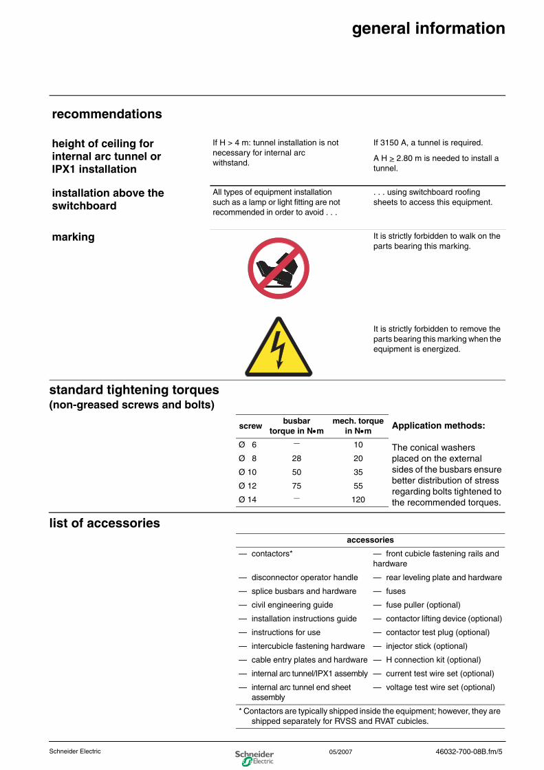
standard tightening torques(non-greased screws and bolts)
list of accessories
recommendations
height of ceiling for internal arc tunnel or IPX1 installation
If H > 4 m: tunnel installation is not necessary for internal arc withstand.
If 3150 A, a tunnel is required.
A H > 2.80 m is needed to install a tunnel.
installation above the switchboard
All types of equipment installation such as a lamp or light fitting are not recommended in order to avoid . . .
. . . using switchboard roofing sheets to access this equipment.
marking It is strictly forbidden to walk on the parts bearing this marking.
It is strictly forbidden to remove the parts bearing this marking when the equipment is energized.
screwbusbar
torque in N•mmech. torque
in N•m
Ø 6 — 10
Ø 8 28 20
Ø 10 50 35
Ø 12 75 55
Ø 14 — 120
accessories
— contactors* — front cubicle fastening rails and hardware
— disconnector operator handle — rear leveling plate and hardware
— splice busbars and hardware — fuses
— civil engineering guide — fuse puller (optional)
— installation instructions guide — contactor lifting device (optional)
— instructions for use — contactor test plug (optional)
— intercubicle fastening hardware — injector stick (optional)
— cable entry plates and hardware — H connection kit (optional)
— internal arc tunnel/IPX1 assembly — current test wire set (optional)
— internal arc tunnel end sheet assembly
— voltage test wire set (optional)
* Contactors are typically shipped inside the equipment; however, they are shipped separately for RVSS and RVAT cubicles.
Application methods:
The conical washers placed on the external sides of the busbars ensure better distribution of stress regarding bolts tightened to the recommended torques.
46032-700-08B.fm/505/2007

0
46032-700-08B.fm/6 Schneider Electric05/2007
0general description
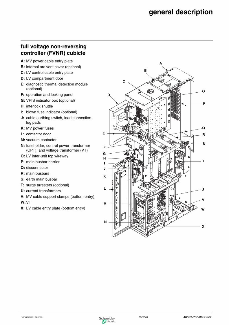
full voltage non-reversing controller (FVNR) cubicleA: MV power cable entry plate
B: internal arc vent cover (optional)
C: LV control cable entry plate
D: LV compartment door
E: diagnostic thermal detection module (optional)
F: operation and locking panel
G: VPIS indicator box (optional)
H. interlock shuttle
I: blown fuse indicator (optional)
J: cable earthing switch, load connection lug pads
K: MV power fuses
L: contactor door
M: vacuum contactor
N: fuseholder, control power transformer (CPT), and voltage transformer (VT)
O: LV inter-unit top wireway
P: main busbar barrier
Q: disconnector
R: main busbars
S: earth main busbar
T: surge arresters (optional)
U: current transformers
V: MV cable support clamps (bottom entry)
W:VT
X: LV cable entry plate (bottom entry)
B
C
D
E
F
G
J
K
L
M
O
P
R
T
S
U
A
V
W
NX
I
Q
H
46032-700-08B.fm/7Schneider Electric 05/2007
0
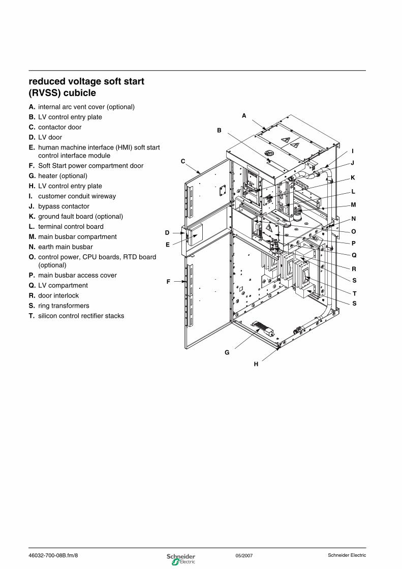
reduced voltage soft start (RVSS) cubicleA. internal arc vent cover (optional)
B. LV control entry plate
C. contactor door
D. LV door
E. human machine interface (HMI) soft start control interface module
F. Soft Start power compartment door
G. heater (optional)
H. LV control entry plate
I. customer conduit wireway
J. bypass contactor
K. ground fault board (optional)
L. terminal control board
M. main busbar compartment
N. earth main busbar
O. control power, CPU boards, RTD board (optional)
P. main busbar access cover
Q. LV compartment
R. door interlock
S. ring transformers
T. silicon control rectifier stacks
A
B
C
D
E
F
G
I
J
K
L
M
N
O
P
Q
R
S
T
S
H
46032-700-08B.fm/8 Schneider Electric05/2007
0
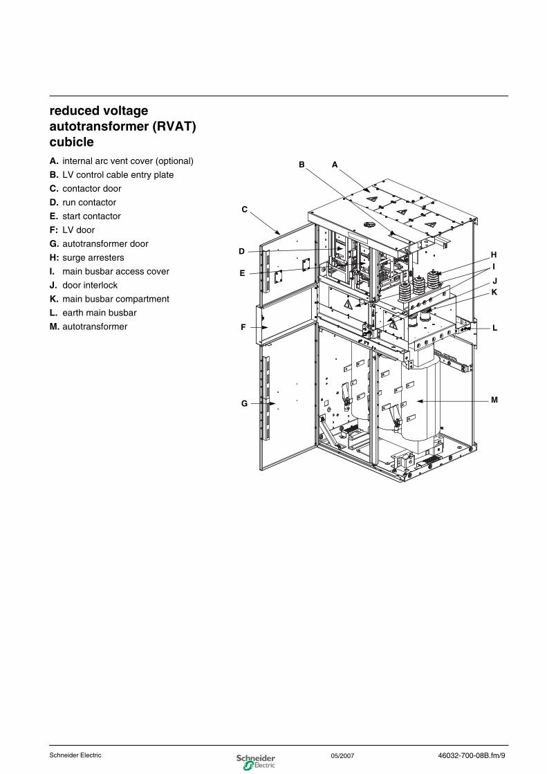
reduced voltage autotransformer (RVAT) cubicleA. internal arc vent cover (optional)
B. LV control cable entry plate
C. contactor door
D. run contactor
E. start contactor
F: LV door
G. autotransformer door
H: surge arresters
I. main busbar access cover
J. door interlock
K. main busbar compartment
L. earth main busbar
M. autotransformer
AB
C
D
E
F
G
J
I
K
L
M
H
46032-700-08B.fm/9Schneider Electric 05/2007
0
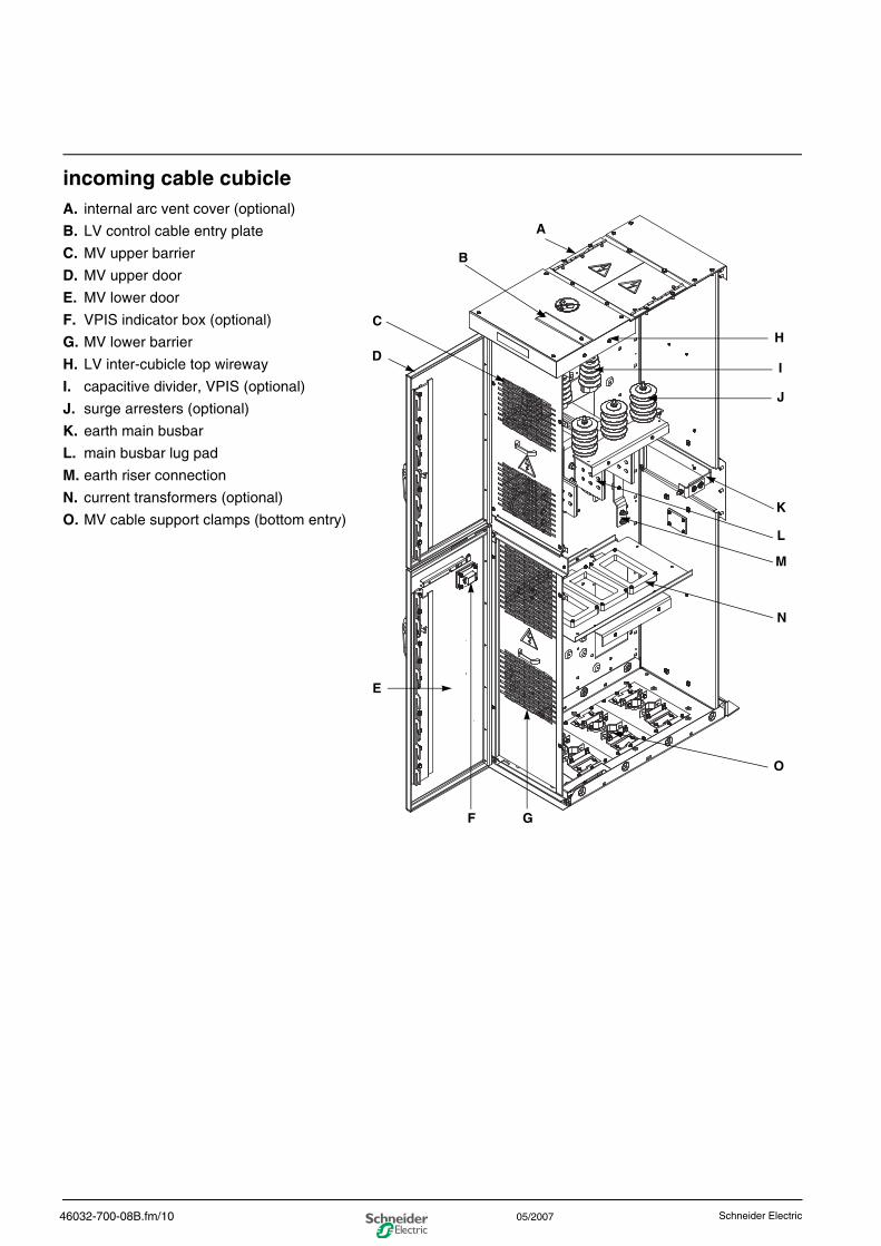
incoming cable cubicleA. internal arc vent cover (optional)
B. LV control cable entry plate
C. MV upper barrier
D. MV upper door
E. MV lower door
F. VPIS indicator box (optional)
G. MV lower barrier
H. LV inter-cubicle top wireway
I. capacitive divider, VPIS (optional)
J. surge arresters (optional)
K. earth main busbar
L. main busbar lug pad
M. earth riser connection
N. current transformers (optional)
O. MV cable support clamps (bottom entry)
A
B
C
D
E
O
H
I
J
K
L
M
N
F G
46032-700-08B.fm/10 Schneider Electric05/2007

0
46032-700-08B.fm/11Schneider Electric 05/2007
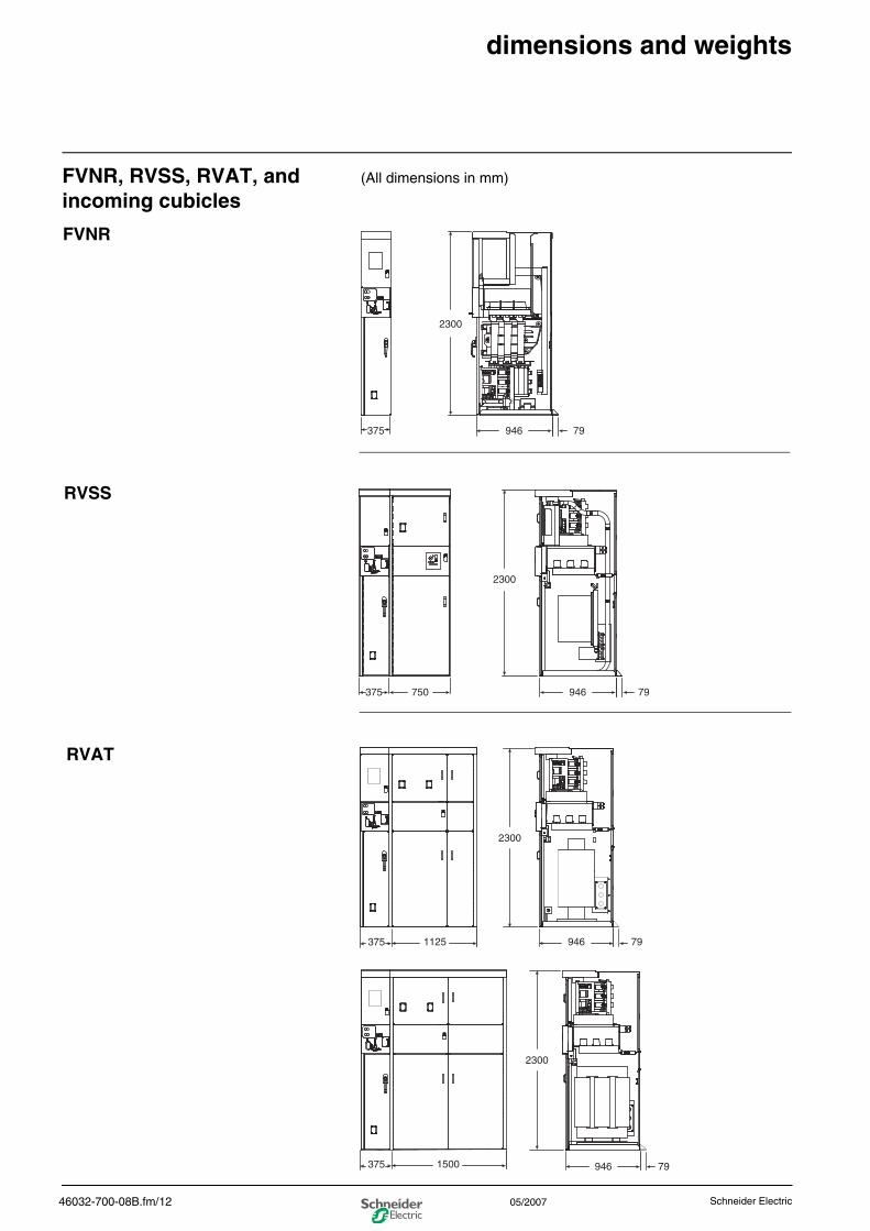
0dimensions and weights
FVNR, RVSS, RVAT, and incoming cubicles
(All dimensions in mm)
946375 79
2300
FVNR
946750375 79
2300
RVSS
946 79
2300
2300
1125
946 79
375
1500375
RVAT
46032-700-08B.fm/12 Schneider Electric05/2007
0
approximate weights
946 79
2300
508
946 79
2300
416
749
554
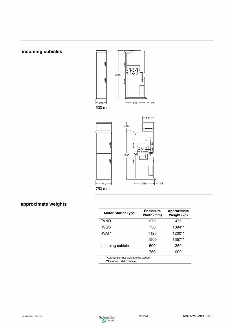
incoming cubicles
500 mm
750 mm
Motor Starter TypeEnclosure
Width (mm)Approximate Weight (kg)
FVNR 375 472
RVSS 750 1094**
RVAT* 1125 1200**
1500 1357**
incoming cubicle 500 350
750 900*Autotransformer weight to be added**Includes FVNR module
46032-700-08B.fm/13Schneider Electric 05/2007

0
46032-700-08B.fm/14 Schneider Electric05/2007
0instructions for receiving,handling, storing
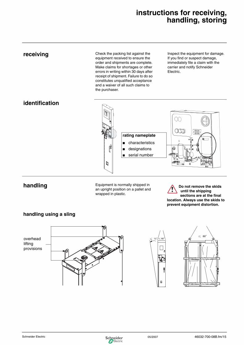
receiving Check the packing list against the equipment received to ensure the order and shipments are complete. Make claims for shortages or other errors in writing within 30 days after receipt of shipment. Failure to do so constitutes unqualified acceptance and a waiver of all such claims to the purchaser.
Inspect the equipment for damage. If you find or suspect damage, immediately file a claim with the carrier and notify Schneider Electric.
identification
rating nameplate
■ characteristics
■ designations
■ serial number
handling Equipment is normally shipped in an upright position on a pallet and wrapped in plastic.
handling using a sling
Do not remove the skids until the shipping sections are at the final
location. Always use the skids to prevent equipment distortion.
overhead lifting provisions
46032-700-08B.fm/15Schneider Electric 05/2007
0
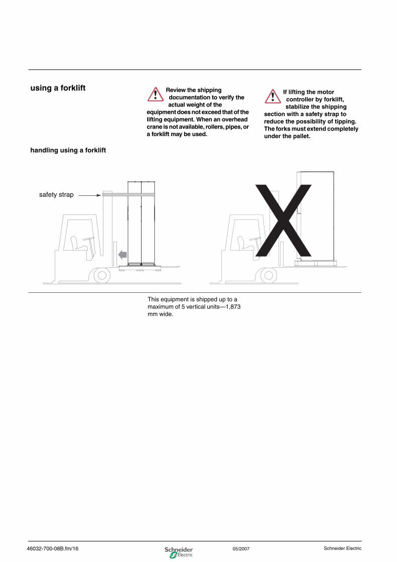
using a forklift
handling using a forklift
This equipment is shipped up to a maximum of 5 vertical units—1,873 mm wide.
Review the shipping documentation to verify the actual weight of the
equipment does not exceed that of the lifting equipment. When an overhead crane is not available, rollers, pipes, or a forklift may be used.
If lifting the motor controller by forklift, stabilize the shipping
section with a safety strap to reduce the possibility of tipping. The forks must extend completely under the pallet.
safety strap
46032-700-08B.fm/16 Schneider Electric05/2007
0
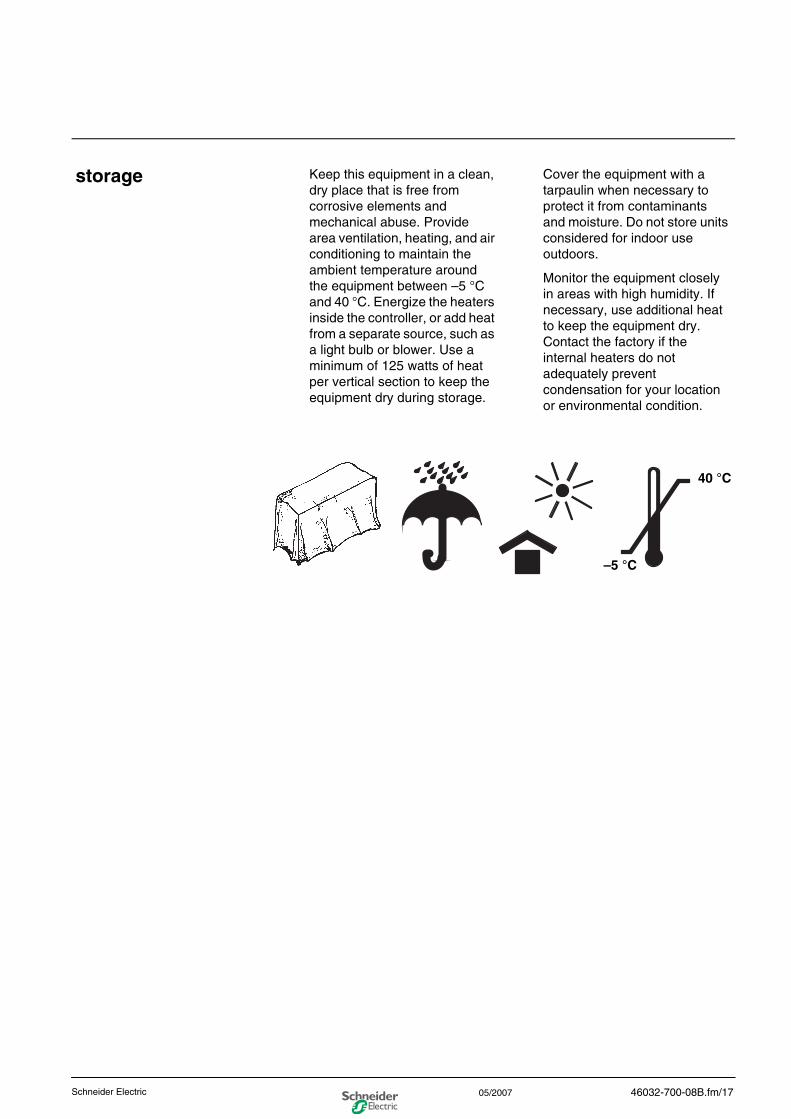
storage Keep this equipment in a clean, dry place that is free from corrosive elements and mechanical abuse. Provide area ventilation, heating, and air conditioning to maintain the ambient temperature around the equipment between –5 °C and 40 °C. Energize the heaters inside the controller, or add heat from a separate source, such as a light bulb or blower. Use a minimum of 125 watts of heat per vertical section to keep the equipment dry during storage.
Cover the equipment with a tarpaulin when necessary to protect it from contaminants and moisture. Do not store units considered for indoor use outdoors.
Monitor the equipment closely in areas with high humidity. If necessary, use additional heat to keep the equipment dry. Contact the factory if the internal heaters do not adequately prevent condensation for your location or environmental condition.
–5 °C
40 °C
46032-700-08B.fm/17Schneider Electric 05/2007

0
46032-700-08B.fm/18 Schneider Electric05/2007
0installation and operationrecommendation
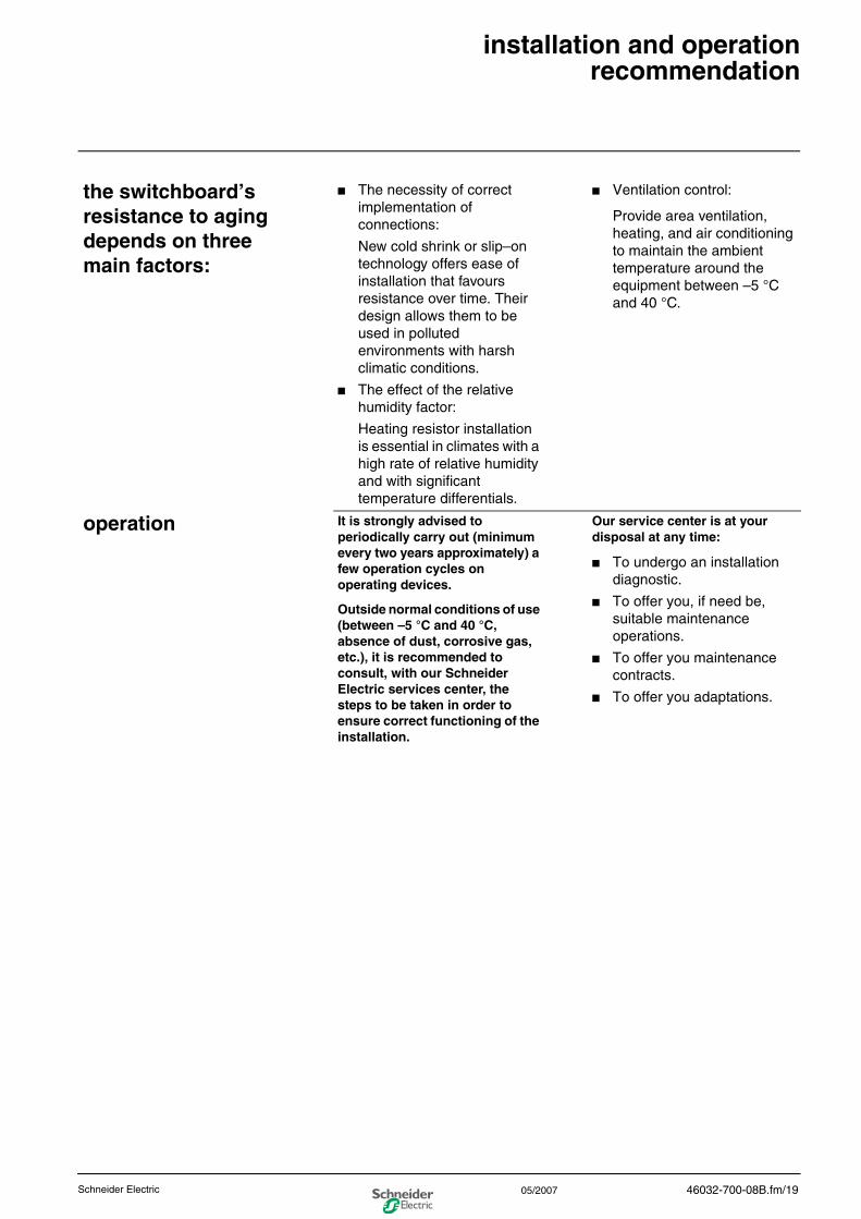
the switchboard’s resistance to aging depends on three main factors:
■ The necessity of correct implementation of connections:
New cold shrink or slip–on technology offers ease of installation that favours resistance over time. Their design allows them to be used in polluted environments with harsh climatic conditions.
■ The effect of the relative humidity factor:
Heating resistor installation is essential in climates with a high rate of relative humidity and with significant temperature differentials.
■ Ventilation control:
Provide area ventilation, heating, and air conditioning to maintain the ambient temperature around the equipment between –5 °C and 40 °C.
operation It is strongly advised to periodically carry out (minimum every two years approximately) a few operation cycles on operating devices.
Outside normal conditions of use (between –5 °C and 40 °C, absence of dust, corrosive gas, etc.), it is recommended to consult, with our Schneider Electric services center, the steps to be taken in order to ensure correct functioning of the installation.
Our service center is at your disposal at any time:
■ To undergo an installation diagnostic.
■ To offer you, if need be, suitable maintenance operations.
■ To offer you maintenance contracts.
■ To offer you adaptations.
46032-700-08B.fm/19Schneider Electric 05/2007

0
46032-700-08B.fm/20 Schneider Electric05/2007
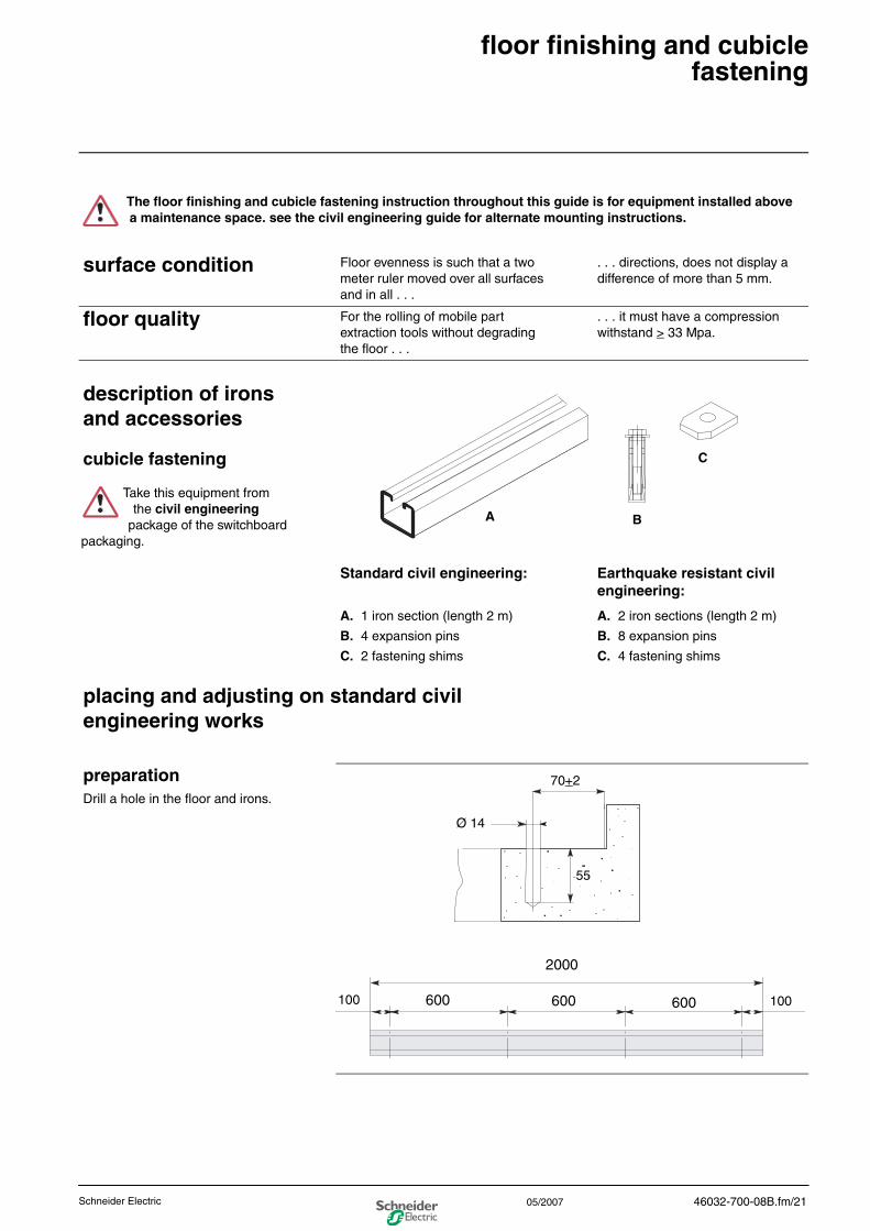
0floor finishing and cubiclefastening
surface condition Floor evenness is such that a two meter ruler moved over all surfaces and in all . . .
. . . directions, does not display a difference of more than 5 mm.
floor quality For the rolling of mobile part extraction tools without degrading the floor . . .
. . . it must have a compression withstand > 33 Mpa.
The floor finishing and cubicle fastening instruction throughout this guide is for equipment installed above a maintenance space. see the civil engineering guide for alternate mounting instructions.
description of irons and accessories
cubicle fastening
Standard civil engineering:
A. 1 iron section (length 2 m)
B. 4 expansion pins
C. 2 fastening shims
Earthquake resistant civil engineering:
A. 2 iron sections (length 2 m)
B. 8 expansion pins
C. 4 fastening shims
placing and adjusting on standard civil engineering works
preparationDrill a hole in the floor and irons.
Take this equipment from the civil engineering package of the switchboard
packaging.
A B
C
70+2
Ø 14
55
100100 600 600 600
2000
46032-700-08B.fm/21Schneider Electric 05/2007
0
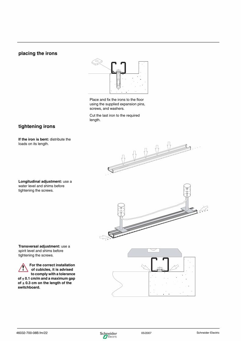
placing the irons
Place and fix the irons to the floor using the supplied expansion pins, screws, and washers.
Cut the last iron to the required length.
tightening irons
If the iron is bent: distribute the loads on its length.
Longitudinal adjustment: use a water level and shims before tightening the screws.
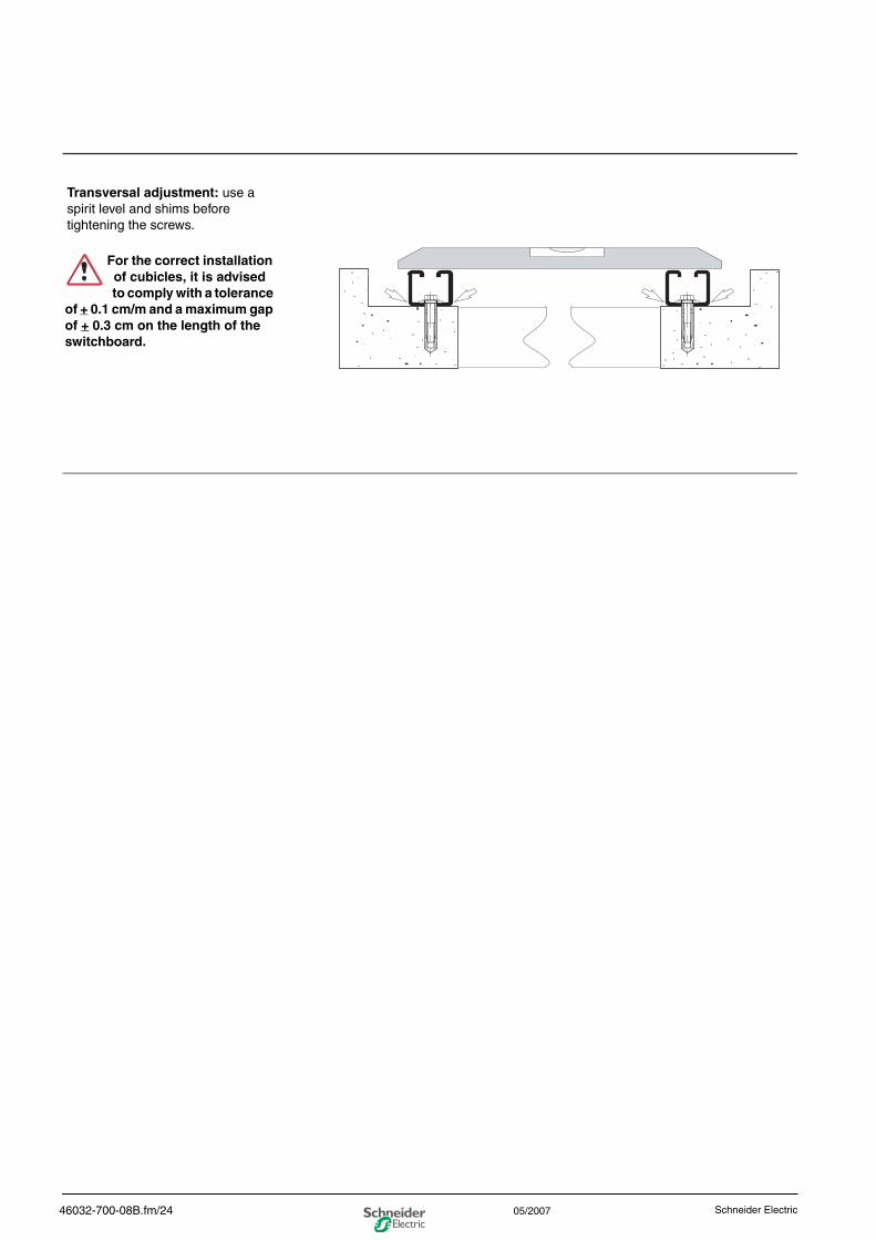
Transversal adjustment: use a spirit level and shims before tightening the screws.
For the correct installation of cubicles, it is advised to comply with a tolerance
of + 0.1 cm/m and a maximum gap of + 0.3 cm on the length of the switchboard.
46032-700-08B.fm/22 Schneider Electric05/2007
0
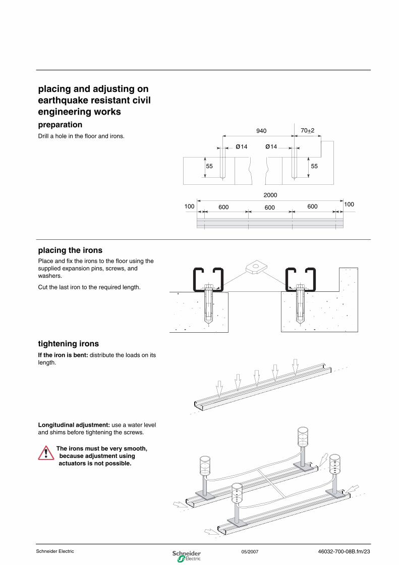
placing and adjusting on earthquake resistant civil engineering workspreparationDrill a hole in the floor and irons.
placing the ironsPlace and fix the irons to the floor using the supplied expansion pins, screws, and washers.
Cut the last iron to the required length.
tightening ironsIf the iron is bent: distribute the loads on its length.
Longitudinal adjustment: use a water level and shims before tightening the screws.
940
ø14 ø14
55
100 100
55
2000
600 600 600
70+2
The irons must be very smooth, because adjustment using actuators is not possible.
46032-700-08B.fm/23Schneider Electric 05/2007
0
Transversal adjustment: use a spirit level and shims before tightening the screws.
For the correct installation of cubicles, it is advised to comply with a tolerance
of + 0.1 cm/m and a maximum gap of + 0.3 cm on the length of the switchboard.
46032-700-08B.fm/24 Schneider Electric05/2007

0
46032-700-08B.fm/25Schneider Electric 05/2007

0installation instructions
placing cubicles in a switchboard lineupassembling, adjusting, and fastening
Place the switchboard cubicles according to front panel drawings and the single–line diagram.
Start by placing the cubicle located in the middle of the switchboard (except in the case of an extension of the existing switchboard) then position the cubicles on either side of it, according to the Civil Engineering Guide indications.
1 bag of standard civil engineering screws and bolts containing:
■ rear adjustment accessories–
A. 4 x HM12 nuts (lock nuts)
B. 2 quick cage nuts
C. 5 flat washers
D. 4 x HM12 x 70 screws (actuators)
E. 2 support irons
■ front fastening accessories–F. 2 hook head bolts
G. 2 fastening shims
1 bag of earthquake resistant civil engineering screws and bolts containing:
■ front fastening accessories–H. 2 hook head bolts
I. 2 fastening shims
■ rear fastening accessories–
H. 2 hook head bolts
J. 2 fastening shims
Check customer drawings to see if front-only accessibility and shielded
cables are required. The cables may need to be prepared before the equipment is placed in position.
Depending on the type of civil engineering, take the following from package 1 of
the cubicle packaging:
A
B
C
D
E
F
G
H
IJ
46032-700-08B.fm/26 Schneider Electric05/2007
0
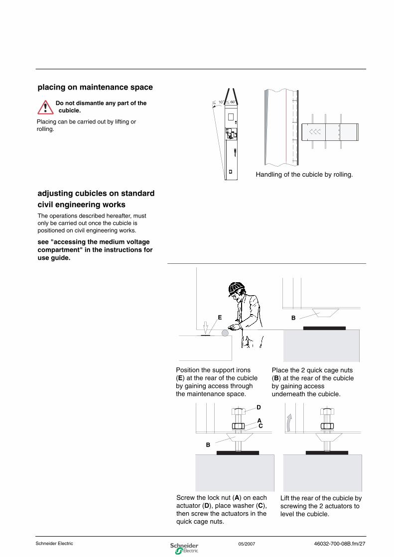
placing on maintenance space
adjusting cubicles on standard civil engineering worksThe operations described hereafter, must only be carried out once the cubicle is positioned on civil engineering works.
see "accessing the medium voltage compartment" in the instructions for use guide.
Handling of the cubicle by rolling.
Do not dismantle any part of the cubicle.
Placing can be carried out by lifting or rolling.
Position the support irons (E) at the rear of the cubicle by gaining access through the maintenance space.
Place the 2 quick cage nuts (B) at the rear of the cubicle by gaining access underneath the cubicle.
Screw the lock nut (A) on each actuator (D), place washer (C), then screw the actuators in the quick cage nuts.
Lift the rear of the cubicle by screwing the 2 actuators to level the cubicle.
B
C
E
B
A
D
46032-700-08B.fm/27Schneider Electric 05/2007
0
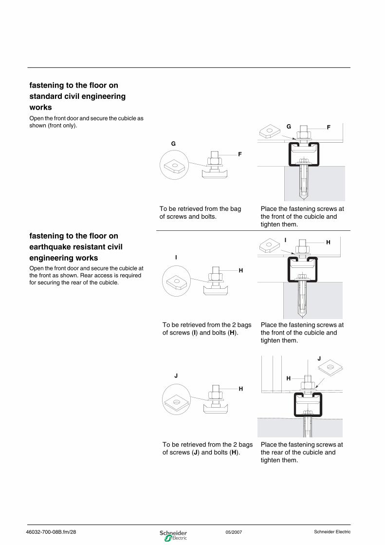
fastening to the floor on standard civil engineering worksOpen the front door and secure the cubicle as shown (front only).
fastening to the floor on earthquake resistant civil engineering worksOpen the front door and secure the cubicle at the front as shown. Rear access is required for securing the rear of the cubicle.
To be retrieved from the bag of screws and bolts.
Place the fastening screws at the front of the cubicle and tighten them.
G
F
G F
Place the fastening screws at the front of the cubicle and tighten them.
To be retrieved from the 2 bags of screws (I) and bolts (H).
Place the fastening screws at the rear of the cubicle and tighten them.
To be retrieved from the 2 bags of screws (J) and bolts (H).
I
H
I H
J
H
J
H
46032-700-08B.fm/28 Schneider Electric05/2007
0
seismic certification of motorpact medium voltage (mv) motor controllers
Motorpact MV motor controllers that are seismically certified have been qualified for the site-specific seismic requirements of the listed model building codes and standards. Optional construction features may be required, depending on the location of the installation and the particular code and standard of interest. Seismic certificates of compliance and equipment labels are provided with all seismically certified equipment. To maintain the validity of this certification, the installation instructions provided in this bulletin must be followed.
responsibility for mitigation of seismic damage
For the purposes of the model building codes, Motorpact MV motor controllers are considered nonstructural building components. Equipment capacity was determined from tri-axial seismic shake table test results as defined in the International Code Counsel Evaluation Service (ICC ES) Acceptance Criteria for Seismic Qualification Testing of Nonstructural Components (AC156). Unless otherwise indicated, an equipment importance factor of 1.5 (IP = 1.5) was used, indicating that equipment functionality was verified before and after shaker table seismic simulation testing. This importance factor is indicative of critical facilities where maximizing the probability of post event functionality is a priority. AC156 is published by the ICC ES and has been recognized by the Building Seismic Safety Council (BSSC) as an appropriate methodology in the 2003 National Earthquake Hazard Reduction Program (NEHRP) Commentary (FEMA 450 Part 2). The National Institute of Building Sciences established the BSSC in 1979 to develop and promote regulatory provisions for earthquake risk mitigation at the national level.
Incoming and outgoing cable and conduit must also be considered as related but independent systems. They must be designed and restrained to withstand the forces generated by the seismic event without increasing the load transferred to the equipment. For applications where seismic hazard exists, bottom entry and exit of cable and conduit is preferred. If the spectral acceleration value (Ss as defined by the International Building Code or NFPA 5000) is in excess of 2.67g (such as the New Madrid seismic area), then the equipment must also be braced at the top using a lateral restraint system. A lateral restraint system is required in situations where horizontal motion at the top of the equipment is not be desirable (such as applications where top entry and exit of conduit are used). This system must be capable of transferring the loads created to the load-bearing path of the building structural system.
maintaining seismic certification
Schneider Electric’s seismic qualification of nonstructural components is just one link in the chain of responsibility required to maximize the probability that the equipment will be intact and functional after a seismic event. During a seismic event, the equipment must be able to transfer the loads that are created through the mounting pad and anchorage to the loadbearing path of the building structural system.
The structural civil engineer or consulting engineer of record is responsible for detailing the equipment connection and anchorage requirements (including the lateral restraint system, if appropriate) for the given installation. The installer and manufacturers of the anchorage and lateral restraint system are responsible for assuring that the mounting requirements are met. Schneider Electric is not responsible for the specification and performance of these systems.
46032-700-08B.fm/29Schneider Electric 05/2007
0
Schneider Electric
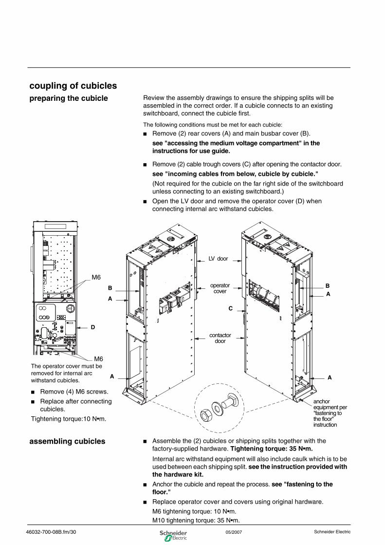
coupling of cubiclespreparing the cubicle Review the assembly drawings to ensure the shipping splits will be
assembled in the correct order. If a cubicle connects to an existing switchboard, connect the cubicle first.
The following conditions must be met for each cubicle:
■ Remove (2) rear covers (A) and main busbar cover (B).
see "accessing the medium voltage compartment" in the instructions for use guide.
■ Remove (2) cable trough covers (C) after opening the contactor door.
see "incoming cables from below, cubicle by cubicle."
(Not required for the cubicle on the far right side of the switchboard unless connecting to an existing switchboard.)
■ Open the LV door and remove the operator cover (D) when connecting internal arc withstand cubicles.
assembling cubicles ■ Assemble the (2) cubicles or shipping splits together with the factory-supplied hardware. Tightening torque: 35 N•m.
Internal arc withstand equipment will also include caulk which is to be used between each shipping split. see the instruction provided with the hardware kit.
■ Anchor the cubicle and repeat the process. see "fastening to the floor."
■ Replace operator cover and covers using original hardware.
M6 tightening torque: 10 N•m. M10 tightening torque: 35 N•m.
BA
B
A
A
C
A
The operator cover must be removed for internal arc withstand cubicles.
■ Remove (4) M6 screws.
■ Replace after connecting cubicles.
Tightening torque:10 N•m.
LV door
operator cover
contactor door
anchor equipment per "fastening to the floor" instruction
M6
M6
D
46032-700-08B.fm/30 05/2007
0
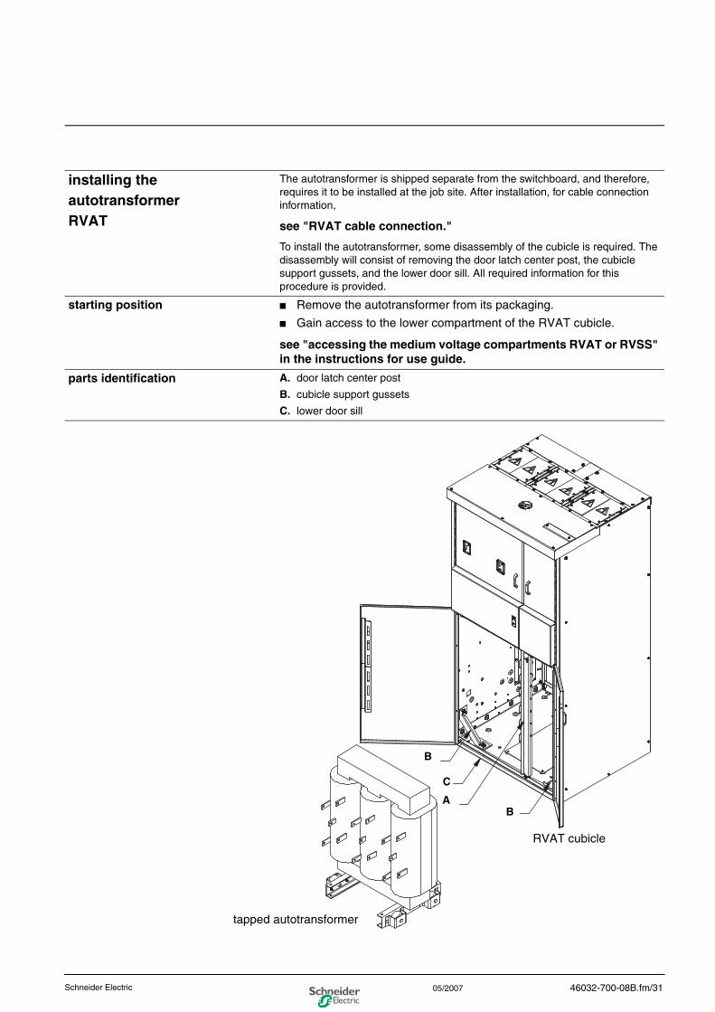
installing the autotransformerRVAT
The autotransformer is shipped separate from the switchboard, and therefore, requires it to be installed at the job site. After installation, for cable connection information,
see "RVAT cable connection."
To install the autotransformer, some disassembly of the cubicle is required. The disassembly will consist of removing the door latch center post, the cubicle support gussets, and the lower door sill. All required information for this procedure is provided.
starting position ■ Remove the autotransformer from its packaging.
■ Gain access to the lower compartment of the RVAT cubicle.
see "accessing the medium voltage compartments RVAT or RVSS" in the instructions for use guide.
parts identification A. door latch center post
B. cubicle support gussets
C. lower door sill
RVAT cubicle
tapped autotransformer
A
B
C
B
46032-700-08B.fm/31Schneider Electric 05/2007
0
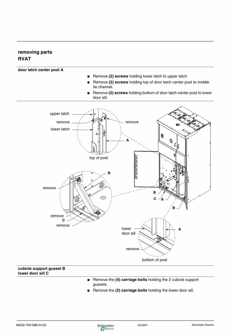
removing partsRVAT
door latch center post A
■ Remove (2) screws holding lower latch to upper latch.
■ Remove (2) screws holding top of door latch center post to middle tie channel.
■ Remove (2) screws holding bottom of door latch center post to lower door sill.
cubicle support gusset Blower door sill C
■ Remove the (4) carriage bolts holding the 2 cubicle support gussets.
■ Remove the (2) carriage bolts holding the lower door sill.
remove
removeremove
lower latch
top of post
A
B
B
C
remove
removeC
B
A
remove
bottom of post
lowerdoor sill
A
upper latch
46032-700-08B.fm/32 Schneider Electric05/2007
0
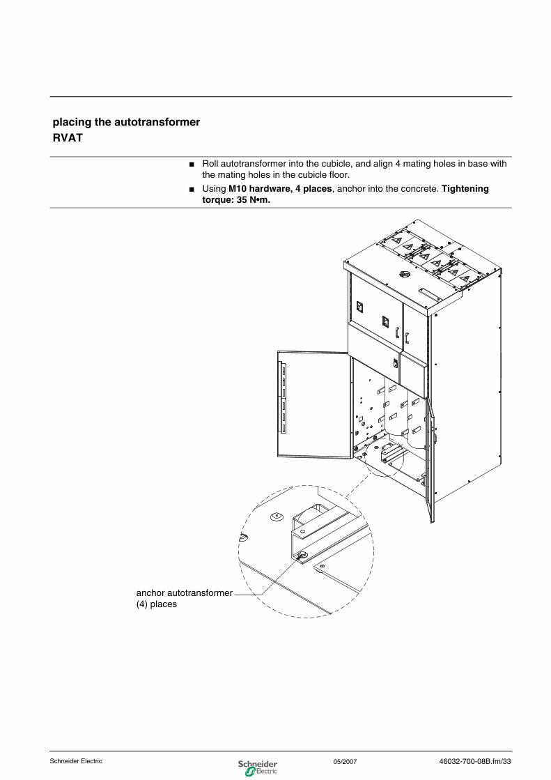
placing the autotransformerRVAT
■ Roll autotransformer into the cubicle, and align 4 mating holes in base with the mating holes in the cubicle floor.
■ Using M10 hardware, 4 places, anchor into the concrete. Tightening torque: 35 N•m.
anchor autotransformer (4) places
46032-700-08B.fm/33Schneider Electric 05/2007
0
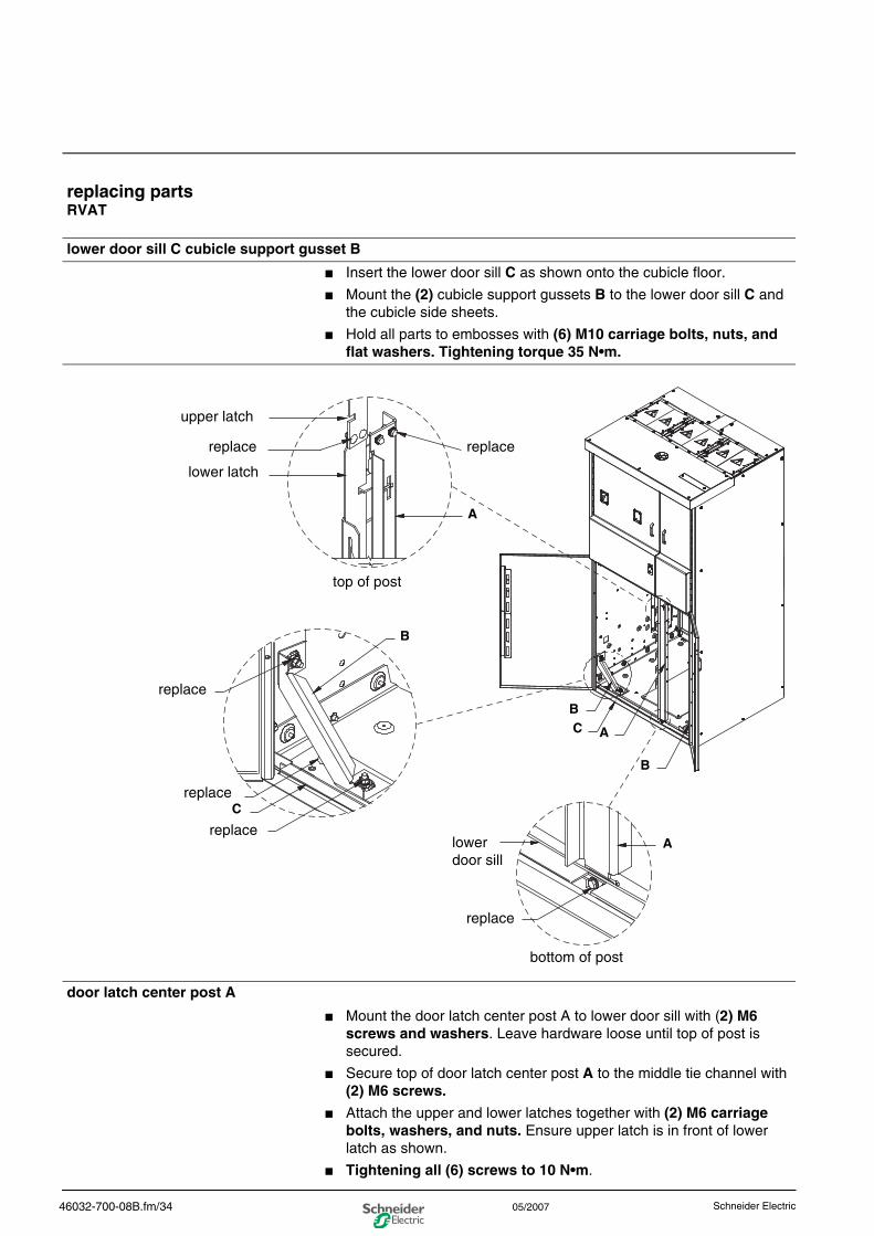
replacing partsRVAT
lower door sill C cubicle support gusset B
■ Insert the lower door sill C as shown onto the cubicle floor.
■ Mount the (2) cubicle support gussets B to the lower door sill C and the cubicle side sheets.
■ Hold all parts to embosses with (6) M10 carriage bolts, nuts, and flat washers. Tightening torque 35 N•m.
door latch center post A
■ Mount the door latch center post A to lower door sill with (2) M6 screws and washers. Leave hardware loose until top of post is secured.
■ Secure top of door latch center post A to the middle tie channel with (2) M6 screws.
■ Attach the upper and lower latches together with (2) M6 carriage bolts, washers, and nuts. Ensure upper latch is in front of lower latch as shown.
■ Tightening all (6) screws to 10 N•m.
replace
replacereplace
lower latch
top of post
A
B
B
C
replace
replace
C
B
A
replace
bottom of post
lowerdoor sill
A
upper latch
46032-700-08B.fm/34 Schneider Electric05/2007
0
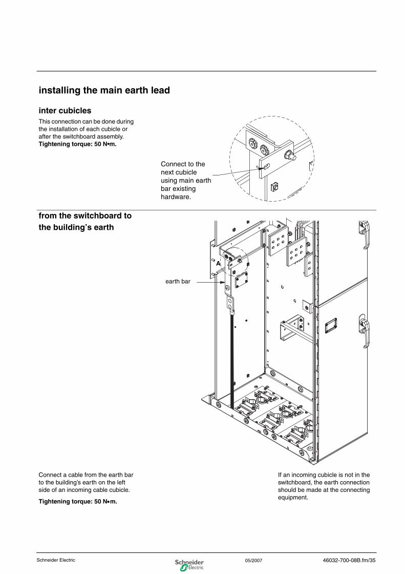
installing the main earth lead
inter cubiclesThis connection can be done during the installation of each cubicle or after the switchboard assembly.Tightening torque: 50 N•m.
from the switchboard to the building’s earth
Connect a cable from the earth bar to the building’s earth on the left side of an incoming cable cubicle.
Tightening torque: 50 N•m.
If an incoming cubicle is not in the switchboard, the earth connection should be made at the connecting equipment.
Connect to the next cubicle using main earth bar existing hardware.
A
earth bar
46032-700-08B.fm/35Schneider Electric 05/2007
0
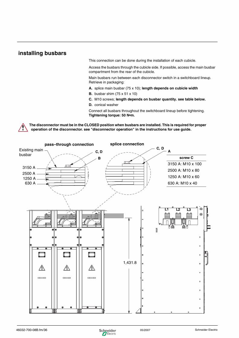
installing busbarsThis connection can be done during the installation of each cubicle.
Access the busbars through the cubicle side. If possible, access the main busbar compartment from the rear of the cubicle.
Main busbars run between each disconnector switch in a switchboard lineup. Retrieve in packaging:
A. splice main busbar (75 x 10); length depends on cubicle width
B. busbar shim (75 x 51 x 10)
C. M10 screws; length depends on busbar quantity. see table below.
D. conical washer
Connect all busbars throughout the switchboard lineup before tightening. Tightening torque: 50 N•m.
The disconnector must be in the CLOSED position when busbars are installed. This is required for proper operation of the disconnector. see "disconnector operation" in the instructions for use guide.
3150 A
Existing main busbar
C,
B
DC, D
A
2500 A1250 A630 A
L1 L2 L3
1,431.8
screw C
3150 A: M10 x 100
2500 A: M10 x 80
1250 A: M10 x 60
630 A: M10 x 40
pass–through connection splice connection
46032-700-08B.fm/36 Schneider Electric05/2007
0
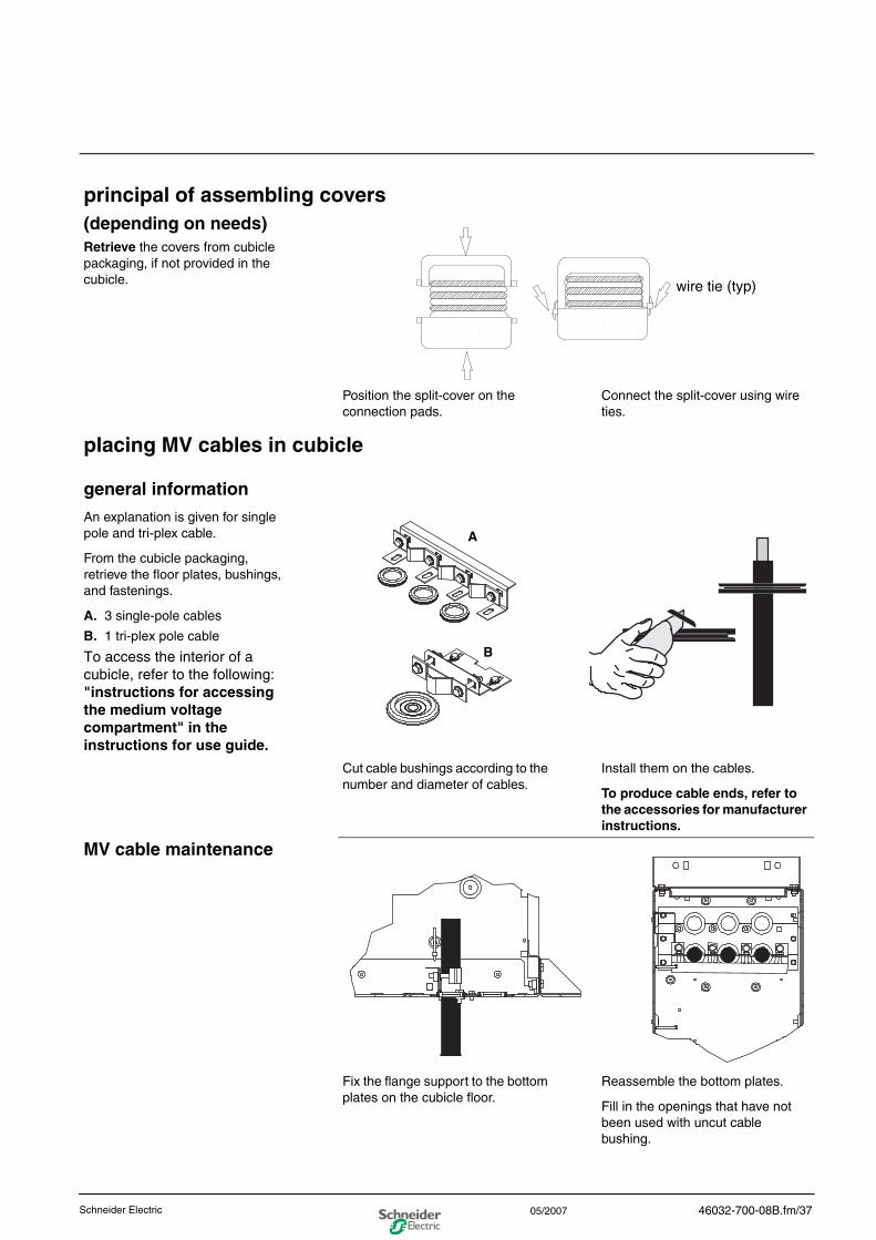
principal of assembling covers(depending on needs)Retrieve the covers from cubicle packaging, if not provided in the cubicle.
Position the split-cover on the connection pads.
Connect the split-cover using wire ties.
placing MV cables in cubicle
general information
An explanation is given for single pole and tri-plex cable.
From the cubicle packaging, retrieve the floor plates, bushings, and fastenings.
A. 3 single-pole cables
B. 1 tri-plex pole cable
To access the interior of a cubicle, refer to the following: "instructions for accessing the medium voltage compartment" in the instructions for use guide.
Cut cable bushings according to the number and diameter of cables.
Install them on the cables.
To produce cable ends, refer to the accessories for manufacturer instructions.
MV cable maintenance
Fix the flange support to the bottom plates on the cubicle floor.
Reassemble the bottom plates.
Fill in the openings that have not been used with uncut cable bushing.
wire tie (typ)
B
A
46032-700-08B.fm/37Schneider Electric 05/2007
0
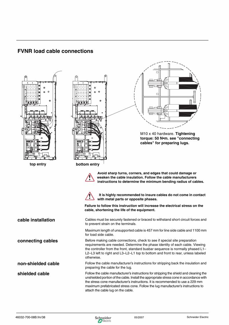
FVNR load cable connections
cable installation Cables must be securely fastened or braced to withstand short circuit forces and to prevent strain on the terminals.
Maximum length of unsupported cable is 457 mm for line side cable and 1100 mm for load side cable.
connecting cables Before making cable connections, check to see if special site preparation requirements are needed. Determine the phase identity of each cable. Viewing the controller from the front, standard busbar sequence is normally phased L1–L2–L3 left to right and L3–L2–L1 top to bottom and front to rear, unless labeled otherwise.
non-shielded cable Follow the cable manufacturer’s instructions for stripping back the insulation and preparing the cable for the lug.
shielded cable Follow the cable manufacturer’s instructions for stripping the shield and cleaning the unshielded portion of the cable. Install the appropriate stress cone in accordance with the stress cone manufacturer’s instructions. It is recommended to use a 229 mm maximum prefabricated stress cone. Follow the lug manufacturer’s instructions to attach the cable lug on the cable.
top entry bottom entry
M10 x 40 hardware. Tightening torque: 50 N•m. see "connecting cables" for preparing lugs.
Avoid sharp turns, corners, and edges that could damage or weaken the cable insulation. Follow the cable manufacturers instructions to determine the minimum bending radius of cables.
It is highly recommended to insure cables do not come in contact with metal parts or opposite phases.
Failure to follow this instruction will increase the electrical stress on the cable, shortening the life of the equipment.
46032-700-08B.fm/38 Schneider Electric05/2007
0
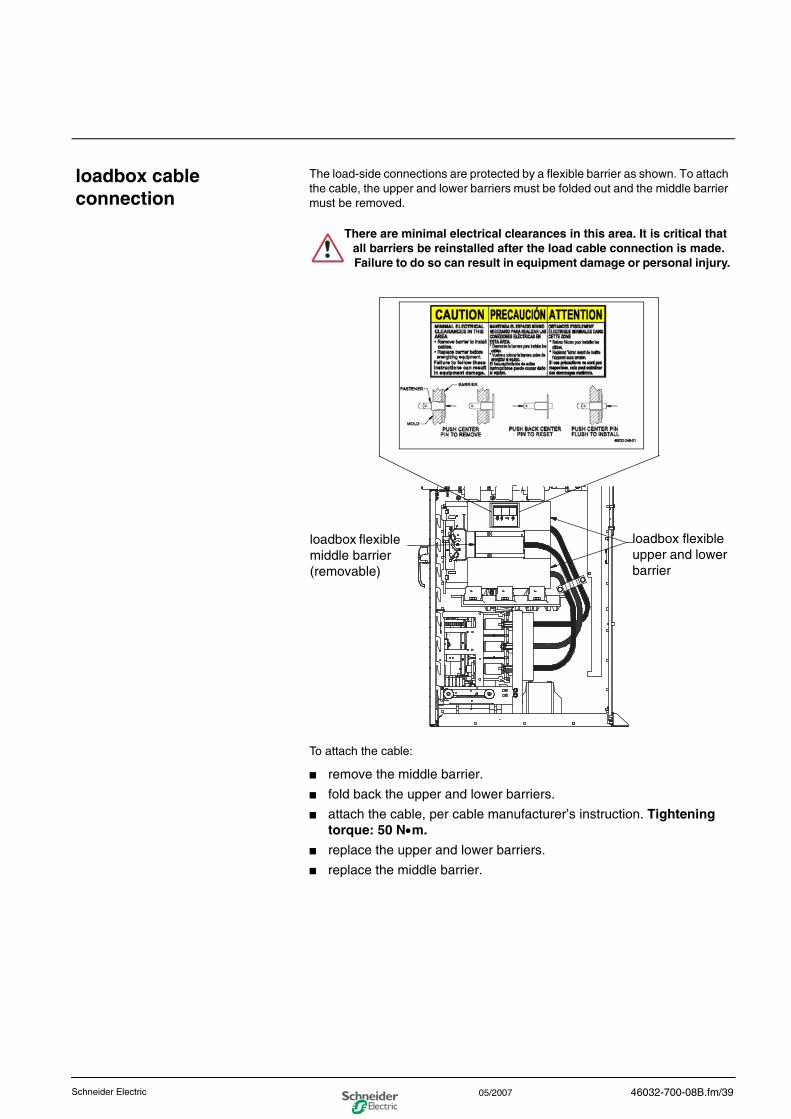
loadbox cable connection
The load-side connections are protected by a flexible barrier as shown. To attach the cable, the upper and lower barriers must be folded out and the middle barrier must be removed.
To attach the cable:
■ remove the middle barrier.
■ fold back the upper and lower barriers.
■ attach the cable, per cable manufacturer’s instruction. Tightening torque: 50 N•m.
■ replace the upper and lower barriers.
■ replace the middle barrier.
There are minimal electrical clearances in this area. It is critical that all barriers be reinstalled after the load cable connection is made. Failure to do so can result in equipment damage or personal injury.
loadbox flexible middle barrier (removable)
loadbox flexible upper and lower barrier
46032-700-08B.fm/39Schneider Electric 05/2007
0
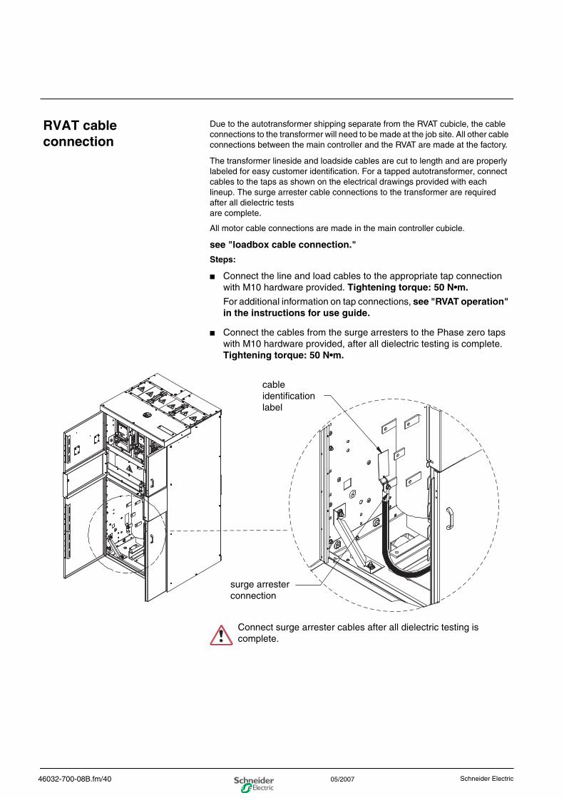
RVAT cable connection
Due to the autotransformer shipping separate from the RVAT cubicle, the cable connections to the transformer will need to be made at the job site. All other cable connections between the main controller and the RVAT are made at the factory.
The transformer lineside and loadside cables are cut to length and are properly labeled for easy customer identification. For a tapped autotransformer, connect cables to the taps as shown on the electrical drawings provided with each lineup. The surge arrester cable connections to the transformer are required after all dielectric tests are complete.
All motor cable connections are made in the main controller cubicle.
see "loadbox cable connection."
Steps:
■ Connect the line and load cables to the appropriate tap connection with M10 hardware provided. Tightening torque: 50 N•m.
For additional information on tap connections, see "RVAT operation" in the instructions for use guide.
■ Connect the cables from the surge arresters to the Phase zero taps with M10 hardware provided, after all dielectric testing is complete. Tightening torque: 50 N•m.
cable identification label
surge arrester connection
Connect surge arrester cables after all dielectric testing is complete.
46032-700-08B.fm/40 Schneider Electric05/2007
0
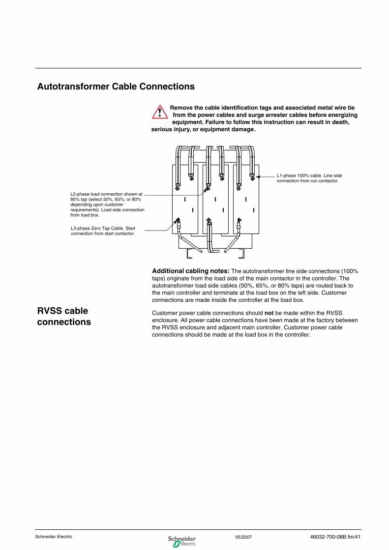
Autotransformer Cable Connections
Additional cabling notes: The autotransformer line side connections (100% taps) originate from the load side of the main contactor in the controller. The autotransformer load side cables (50%, 65%, or 80% taps) are routed back to the main controller and terminate at the load box on the left side. Customer connections are made inside the controller at the load box.
RVSS cable connections
Customer power cable connections should not be made within the RVSS enclosure. All power cable connections have been made at the factory between the RVSS enclosure and adjacent main controller. Customer power cable connections should be made at the load box in the controller.
Remove the cable identification tags and associated metal wire tie from the power cables and surge arrester cables before energizing equipment. Failure to follow this instruction can result in death,
serious injury, or equipment damage.
L1-phase 100% cable. Line side connection from run contactor.
L2-phase load connection shown at 80% tap (select 50%, 65%, or 80% depending upon customer requirements). Load side connection from load box.
L3-phase Zero Tap Cable. Start connection from start contactor.
46032-700-08B.fm/41Schneider Electric 05/2007
0
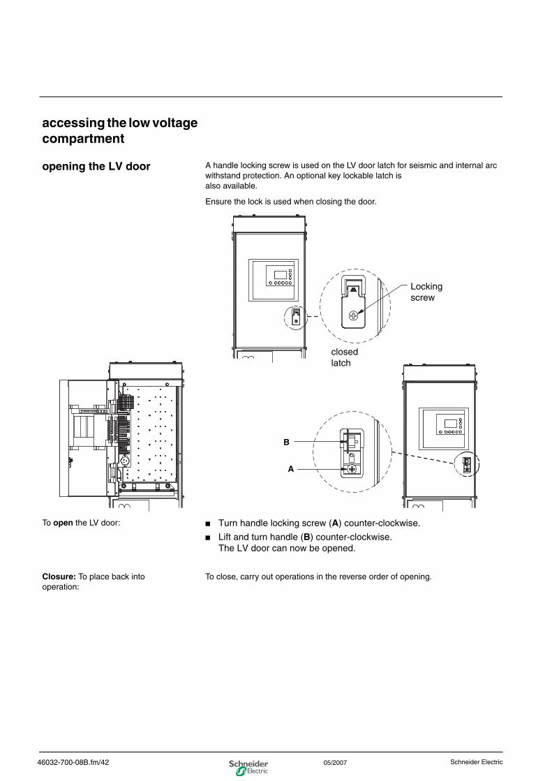
accessing the low voltage compartment
opening the LV door A handle locking screw is used on the LV door latch for seismic and internal arc withstand protection. An optional key lockable latch is also available.
Ensure the lock is used when closing the door.
To open the LV door: ■ Turn handle locking screw (A) counter-clockwise.
■ Lift and turn handle (B) counter-clockwise.The LV door can now be opened.
Closure: To place back into operation:
To close, carry out operations in the reverse order of opening.
Locking screw
A
B
closed latch
46032-700-08B.fm/42 Schneider Electric05/2007
0
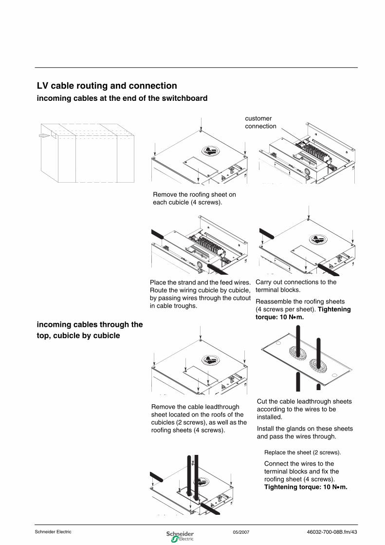
LV cable routing and connectionincoming cables at the end of the switchboard
incoming cables through the top, cubicle by cubicle
Replace the sheet (2 screws).
Connect the wires to the terminal blocks and fix the roofing sheet (4 screws). Tightening torque: 10 N•m.
Remove the roofing sheet on each cubicle (4 screws).
Place the strand and the feed wires. Route the wiring cubicle by cubicle, by passing wires through the cutout in cable troughs.
Carry out connections to the terminal blocks.
Reassemble the roofing sheets (4 screws per sheet). Tightening torque: 10 N•m.
Remove the cable leadthrough sheet located on the roofs of the cubicles (2 screws), as well as the roofing sheets (4 screws).
Cut the cable leadthrough sheets according to the wires to be installed.
Install the glands on these sheets and pass the wires through.
customer connection
46032-700-08B.fm/43Schneider Electric 05/2007
0
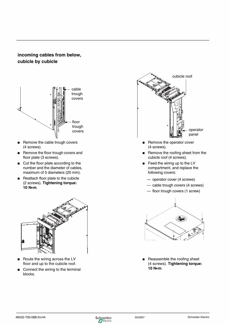
incoming cables from below, cubicle by cubicle
■ Remove the cable trough covers (4 screws).
■ Remove the floor trough covers and floor plate (3 screws).
■ Cut the floor plate according to the number and the diameter of cables, maximum of 5 diameters (20 mm).
■ Reattach floor plate to the cubicle (2 screws). Tightening torque: 10 N•m.
■ Remove the operator cover (4 screws).
■ Remove the roofing sheet from the cubicle roof (4 screws).
■ Feed the wiring up to the LV compartment, and replace the following covers:
— operator cover (4 screws)
— cable trough covers (4 screws)
— floor trough covers (1 screw)
■ Route the wiring across the LV floor and up to the cubicle roof.
■ Connect the wiring to the terminal blocks.
■ Reassemble the roofing sheet (4 screws). Tightening torque: 10 N•m.
cable trough covers
floor trough covers
cubicle roof
operator panel
46032-700-08B.fm/44 Schneider Electric05/2007
0
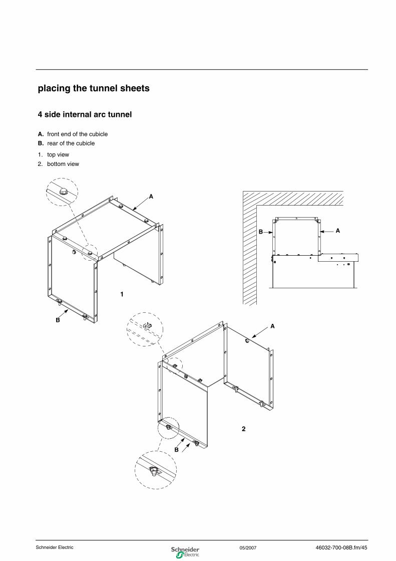
placing the tunnel sheets
4 side internal arc tunnel
A. front end of the cubicle
B. rear of the cubicle
1. top view
2. bottom view
A
A
AB
B
B
1
2
46032-700-08B.fm/45Schneider Electric 05/2007
0
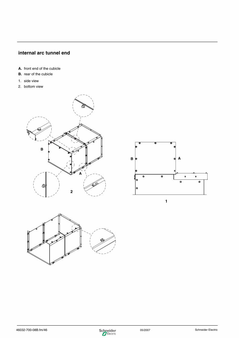
internal arc tunnel end
A. front end of the cubicle
B. rear of the cubicle
1. side view
2. bottom view
A
A
B
B
1
2
46032-700-08B.fm/46 Schneider Electric05/2007
0
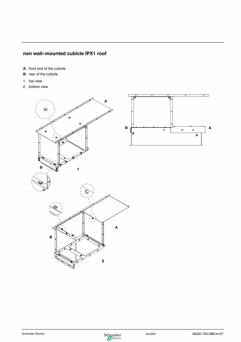
non wall–mounted cubicle IPX1 roof
A. front end of the cubicle
B. rear of the cubicle
1. top view
2. bottom view
A
A
B
B
1
2
B A
46032-700-08B.fm/47Schneider Electric 05/2007

0
46032-700-08B.fm/48 Schneider Electric05/2007
0steps to be taken for tests andinspections
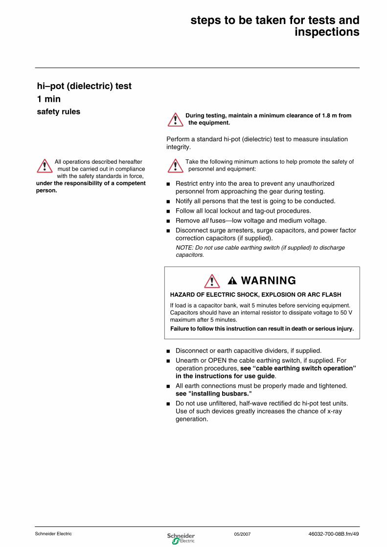
hi–pot (dielectric) test1 minsafety rules
Perform a standard hi-pot (dielectric) test to measure insulation integrity.
■ Restrict entry into the area to prevent any unauthorized personnel from approaching the gear during testing.
■ Notify all persons that the test is going to be conducted.
■ Follow all local lockout and tag-out procedures.
■ Remove all fuses—low voltage and medium voltage.
■ Disconnect surge arresters, surge capacitors, and power factor correction capacitors (if supplied).NOTE: Do not use cable earthing switch (if supplied) to discharge capacitors.
HAZARD OF ELECTRIC SHOCK, EXPLOSION OR ARC FLASH
If load is a capacitor bank, wait 5 minutes before servicing equipment. Capacitors should have an internal resistor to dissipate voltage to 50 V maximum after 5 minutes.
Failure to follow this instruction can result in death or serious injury.
■ Disconnect or earth capacitive dividers, if supplied.
■ Unearth or OPEN the cable earthing switch, if supplied. For operation procedures, see “cable earthing switch operation” in the instructions for use guide.
■ All earth connections must be properly made and tightened. see "installing busbars."
■ Do not use unfiltered, half-wave rectified dc hi-pot test units. Use of such devices greatly increases the chance of x-ray generation.
During testing, maintain a minimum clearance of 1.8 m from the equipment.
All operations described hereafter must be carried out in compliance with the safety standards in force,
under the responsibility of a competent person.
Take the following minimum actions to help promote the safety of personnel and equipment:
WARNING
46032-700-08B.fm/49Schneider Electric 05/2007
0
phase-to-phase hi-pot testing Follow these steps to perform a phase-to-phase hi-pot test:
■ Perform a phase-to-phase hi-pot test on the main busbar.
— Gradually increase the voltage to the test levels of the standards in force.
— Verify that the equipment sustains the required voltage without flashover for one minute.
■ Turn off the test equipment. Discharge to earth the phase busbar before removing the test cables.
phase-to-ground hi-pot testing Follow these steps to perform a phase-to-ground hi-pot test:
■ Perform a phase-to-earth hi-pot test on the main busbar.
— Gradually increase the voltage to the levels shown in the test levels of the standards in force.
— Verify that the equipment sustains the required voltage without flashover for one minute.
■ Turn off the test equipment. Discharge to earth the phase busbar before removing the test cables.
If the test is unsuccessful, inspect the insulators for leakage paths. If necessary, clean the surface of the insulator(s) with denatured alcohol and re-test. If problems persist, DO NOT ENERGIZE THE EQUIPMENT. Contact your local field sales office or your distributor.
If the equipment has been stored for several months or has been exposed to high humidity during the storage time period, PERFORM A STANDARD HI–POT (DIELECTRIC) TEST. First energize the heater circuits for a minimum of 24 hours. Follow other equipment testing procedures as required by customer in-house standards.
After completing hi–pot testing, temporarily earth the busbars to remove any residual charges.
Failure to follow this instruction can result in injury.
46032-700-08B.fm/50 Schneider Electric05/2007
0
final inspection
After installing the equipment and making all interconnections, follow the steps below to test the equipment and perform a final inspection before placing it in service.
Verify that a hi-pot test has been performed recently.
Check all control wiring with the wiring diagrams. Verify that all connections are properly made and tightened, all secondary fuses are installed, current transformer circuits are complete, all fault detection devices have been properly connected and set, and that loose connections are tightened to the proper tightening torque.
Verify that all protective relays have been configured with proper settings per the outcome of customer’s coordination study.
Verify that all insulating surfaces, including the primary support insulators and isolation barriers, are clean and dry.
Verify that all primary fuses are installed and orientated properly and do not exceed the nameplate rating for their cubicles. see "installing fuses" in the instructions for use guide.
Verify all surge arresters, surge capacitors, and power factor correction capacitors are connected. see "standard tightening torques."
Before energizing any source of electric power, make a final check of the equipment. Inspect every compartment for loose parts, tools, litter, and miscellaneous construction items.
Review key interlock schemes carefully (if used). Insert only the proper keys in the locks. Remove all extra keys and store them where only authorized personnel can access them.
Verify that all barriers, covers, and doors are secured using the original mounting hardware.
ALWAYS assume that all circuits are live until they have been completely de-energized, tested, earthed, and tagged.
Follow all lock-out/tag-out procedures. If disconnect switches cannot be opened, disconnect the line leads.
The following operations must only be carried out after dielectric tests and before the equipment is energized.
46032-700-08B.fm/51Schneider Electric 05/2007
Mot
orpa
ct ©
200
4—20
07 -
Sch
neid
er E
lect
ric -
All
right
s re
serv
ed.
Schneider Electric Industries SASAddress:330 Weakley RoadSmyrna, TN 37167, USA1888-778-2377
http:/www.schneiderelectric.com
46032-700-08B 05/2007
The Schneider group service centers are at your service for:
engineering and technical assistancecommissioningtrainingpreventive and corrective maintenanceadaptationspare parts.
Contact your sales representative who will put youin touch with your nearest Schneider group service center or call us on 33 (0)4 76 57 60 60 (Grenoble, France).
As standards, specifications and designs change from time to time, please ask for confirmation of the information given in this publication.
This document has been printed on ecological paper.
Design: Schneider Electric Technical Publications Department, Nashville, TN, USA