Embed Size (px)
Citation preview

Level 1 and 2 Service Manual6809495A75-O
L6Digital Wireless Telephone
GSM 850/1800/1900 or 900/1800/1900 MHz GPRS

6809495A75-O October 14, 2005 3
Level 1 and 2 Service Manual Contents
ContentsContents . . . . . . . . . . . . . . . . . . . . . . . . . . . . . . . . . . . . . . . . . . . . . . . . . . . . . . . . . . . . . . . . . . . . . . . . . . . . . . . . . . . . 3Introduction . . . . . . . . . . . . . . . . . . . . . . . . . . . . . . . . . . . . . . . . . . . . . . . . . . . . . . . . . . . . . . . . . . . . . . . . . . . . . . . . . 4
Product Identification . . . . . . . . . . . . . . . . . . . . . . . . . . . . . . . . . . . . . . . . . . . . . . . . . . . . . . . . . . . . . . . . . . . 4Product Names . . . . . . . . . . . . . . . . . . . . . . . . . . . . . . . . . . . . . . . . . . . . . . . . . . . . . . . . . . . . . . . . . . . . . . . . 4Regulatory Agency Compliance . . . . . . . . . . . . . . . . . . . . . . . . . . . . . . . . . . . . . . . . . . . . . . . . . . . . . . . . . . . 4Computer Program Copyrights . . . . . . . . . . . . . . . . . . . . . . . . . . . . . . . . . . . . . . . . . . . . . . . . . . . . . . . . . . . 5About this Service Manual . . . . . . . . . . . . . . . . . . . . . . . . . . . . . . . . . . . . . . . . . . . . . . . . . . . . . . . . . . . . . . . 5Warranty Service Policy . . . . . . . . . . . . . . . . . . . . . . . . . . . . . . . . . . . . . . . . . . . . . . . . . . . . . . . . . . . . . . . . . 6Parts Replacement . . . . . . . . . . . . . . . . . . . . . . . . . . . . . . . . . . . . . . . . . . . . . . . . . . . . . . . . . . . . . . . . . . . . . 7
Specifications . . . . . . . . . . . . . . . . . . . . . . . . . . . . . . . . . . . . . . . . . . . . . . . . . . . . . . . . . . . . . . . . . . . . . . . . . . . . . . 8Product Overview . . . . . . . . . . . . . . . . . . . . . . . . . . . . . . . . . . . . . . . . . . . . . . . . . . . . . . . . . . . . . . . . . . . . . . . . . . . 10
Features . . . . . . . . . . . . . . . . . . . . . . . . . . . . . . . . . . . . . . . . . . . . . . . . . . . . . . . . . . . . . . . . . . . . . . . . . . . . . 10General Operation . . . . . . . . . . . . . . . . . . . . . . . . . . . . . . . . . . . . . . . . . . . . . . . . . . . . . . . . . . . . . . . . . . . . . . . . . . . 12
Controls, Indicators, and Input/Output (I/O) Connectors . . . . . . . . . . . . . . . . . . . . . . . . . . . . . . . . . . . . . 12User Interface Menu Structure . . . . . . . . . . . . . . . . . . . . . . . . . . . . . . . . . . . . . . . . . . . . . . . . . . . . . . . . . . 14Alert Settings . . . . . . . . . . . . . . . . . . . . . . . . . . . . . . . . . . . . . . . . . . . . . . . . . . . . . . . . . . . . . . . . . . . . . . . . 14Battery Function . . . . . . . . . . . . . . . . . . . . . . . . . . . . . . . . . . . . . . . . . . . . . . . . . . . . . . . . . . . . . . . . . . . . . . 14Operation . . . . . . . . . . . . . . . . . . . . . . . . . . . . . . . . . . . . . . . . . . . . . . . . . . . . . . . . . . . . . . . . . . . . . . . . . . . . 15
Tools and Test Equipment . . . . . . . . . . . . . . . . . . . . . . . . . . . . . . . . . . . . . . . . . . . . . . . . . . . . . . . . . . . . . . . . . . . . 16Disassembly . . . . . . . . . . . . . . . . . . . . . . . . . . . . . . . . . . . . . . . . . . . . . . . . . . . . . . . . . . . . . . . . . . . . . . . . . . . . . . . . 17
Removing and Replacing the Battery Cover . . . . . . . . . . . . . . . . . . . . . . . . . . . . . . . . . . . . . . . . . . . . . . . . 17Removing and Replacing the Battery . . . . . . . . . . . . . . . . . . . . . . . . . . . . . . . . . . . . . . . . . . . . . . . . . . . . . 18Removing and Replacing the SIM . . . . . . . . . . . . . . . . . . . . . . . . . . . . . . . . . . . . . . . . . . . . . . . . . . . . . . . . 19Removing and Replacing the Antenna . . . . . . . . . . . . . . . . . . . . . . . . . . . . . . . . . . . . . . . . . . . . . . . . . . . . 20Removing and Replacing the Transceiver PC Board Shield . . . . . . . . . . . . . . . . . . . . . . . . . . . . . . . . . . . 22Removing and Replacing the Motor/Vibrator . . . . . . . . . . . . . . . . . . . . . . . . . . . . . . . . . . . . . . . . . . . . . . . 23Removing and Replacing the Transceiver PC Board . . . . . . . . . . . . . . . . . . . . . . . . . . . . . . . . . . . . . . . . . 24Removing and Replacing the Camera Assembly. . . . . . . . . . . . . . . . . . . . . . . . . . . . . . . . . . . . . . . . . . . . . 27Removing and Replacing the Front Housing . . . . . . . . . . . . . . . . . . . . . . . . . . . . . . . . . . . . . . . . . . . . . . . . 28Removing and Replacing the Keypad PC Board . . . . . . . . . . . . . . . . . . . . . . . . . . . . . . . . . . . . . . . . . . . . . 30Removing and Replacing the Keypad . . . . . . . . . . . . . . . . . . . . . . . . . . . . . . . . . . . . . . . . . . . . . . . . . . . . . 31Removing and Replacing the Display Module . . . . . . . . . . . . . . . . . . . . . . . . . . . . . . . . . . . . . . . . . . . . . . . 32
Subscriber Identity Module (SIM) and Identification Label . . . . . . . . . . . . . . . . . . . . . . . . . . . . . . . . . . . . . . . . . . 34SIM . . . . . . . . . . . . . . . . . . . . . . . . . . . . . . . . . . . . . . . . . . . . . . . . . . . . . . . . . . . . . . . . . . . . . . . . . . . . . . . . 34Identification . . . . . . . . . . . . . . . . . . . . . . . . . . . . . . . . . . . . . . . . . . . . . . . . . . . . . . . . . . . . . . . . . . . . . . . . . 34
Telephone Identification . . . . . . . . . . . . . . . . . . . . . . . . . . . . . . . . . . . . . . . . . . . . . . . . . . . . . . . . . . . . . . . . . . . . . . 36Identification Label . . . . . . . . . . . . . . . . . . . . . . . . . . . . . . . . . . . . . . . . . . . . . . . . . . . . . . . . . . . . . . . . . . . . 36
Troubleshooting . . . . . . . . . . . . . . . . . . . . . . . . . . . . . . . . . . . . . . . . . . . . . . . . . . . . . . . . . . . . . . . . . . . . . . . . . . . . 37Manual Test Mode . . . . . . . . . . . . . . . . . . . . . . . . . . . . . . . . . . . . . . . . . . . . . . . . . . . . . . . . . . . . . . . . . . . . 37Manual Test Mode Commands . . . . . . . . . . . . . . . . . . . . . . . . . . . . . . . . . . . . . . . . . . . . . . . . . . . . . . . . . . . 37Troubleshooting Chart . . . . . . . . . . . . . . . . . . . . . . . . . . . . . . . . . . . . . . . . . . . . . . . . . . . . . . . . . . . . . . . . . 39Exploded View Diagram . . . . . . . . . . . . . . . . . . . . . . . . . . . . . . . . . . . . . . . . . . . . . . . . . . . . . . . . . . . . . . . . 41Exploded View Parts List . . . . . . . . . . . . . . . . . . . . . . . . . . . . . . . . . . . . . . . . . . . . . . . . . . . . . . . . . . . . . . 42Accessories . . . . . . . . . . . . . . . . . . . . . . . . . . . . . . . . . . . . . . . . . . . . . . . . . . . . . . . . . . . . . . . . . . . . . . . . . . . 43Related Publications . . . . . . . . . . . . . . . . . . . . . . . . . . . . . . . . . . . . . . . . . . . . . . . . . . . . . . . . . . . . . . . . . . . 45Programming: Software Upgrade and Flexing . . . . . . . . . . . . . . . . . . . . . . . . . . . . . . . . . . . . . . . . . . . . . . 45
Index . . . . . . . . . . . . . . . . . . . . . . . . . . . . . . . . . . . . . . . . . . . . . . . . . . . . . . . . . . . . . . . . . . . . . . . . . . . . . . . . . . . . . . . 1
1 and 26809495A75-OL6Contents
4 October 14, 2005 6809495A75-O
Introduction L6
IntroductionMotorola® Inc. maintains a worldwide organization that is dedicated to provide responsive, full-service customer support. Motorola products are serviced by an international network of company-operated product-care centers as well as authorized independent service firms.
Available on a contract basis, Motorola Inc. offers comprehensive maintenance and installation programs that enable customers to meet requirements for reliable, continuous communications.
To learn more about the wide range of Motorola service programs, contact your local Motorola products representative or the nearest Customer Service Manager.
Product IdentificationMotorola products are identified by the model number on the housing. Use the entire model number when inquiring about the product. Numbers are also assigned to chassis and kits. Use these numbers when requesting information or ordering replacement parts.
Product NamesProduct names are listed on the front cover. Product names are subject to change without notice. Some product names, as well as some frequency bands, are available only in certain markets.
Regulatory Agency ComplianceThis device complies with Part 15 of the FCC Rules. Operation is subject to the following conditions:• This device may not cause any harmful interference, and• must accept interference received, including interference that may cause
undesired operation.
This class B device also complies with all requirements of the Canadian Interference-Causing Equipment Regulations (ICES-003).
Cet appareil numérique de la classe B respecte toutes les exigences du Règlement sur le matériel brouilleur du Canada.
1 and 26809495A75-OL6
6809495A75-O October 14, 2005 5
Level 1 and 2 Service Manual Introduction
Computer Program CopyrightsThe Motorola products described in this manual may include Motorola computer programs stored in semiconductor memories or other media that are copyrighted with all rights reserved worldwide to Motorola. Laws in the United States and other countries preserve for Motorola, Inc. certain exclusive rights to the copyrighted computer programs, including the exclusive right to copy, reproduce, modify, decompile, disassemble, and reverse-engineer the Motorola computer programs in any manner or form without Motorola's prior written consent. Furthermore, the purchase of Motorola products shall not be deemed to grant either directly or by implication, estoppel, or otherwise, any license or rights under the copyrights, patents, or patent applications of Motorola, except for a nonexclusive license to use the Motorola product and the Motorola computer programs with the Motorola product.
About this Service ManualUsing this service manual and the suggestions contained in it assures proper installation, operation, and maintenance of wireless telephones. Refer questions about this manual to the nearest Customer Service Manager.
Audience
This manual aids service personnel in testing and repairing of wireless telephones. Service personnel should be familiar with electronic assembly, testing, and troubleshooting methods, and with the operation and use of associated test equipment.
Use of this manual assures proper installation, operation, and maintenance of Motorola products and equipment. It contains all service information required for the equipment described and is current as of the printing date.
Scope
The scope of this manual is to provide basic information relating to wireless telephones, and provide procedures and processes for repairing the phones at Level 1 and 2 service centers including:• Unit swap out• Repairing of mechanical faults• Basic modular troubleshooting• Testing and verification of phone functionality• Initiate warranty claims and send faulty modules to Level 3 or 4 repair
centers
6 October 14, 2005 6809495A75-O
Introduction L6
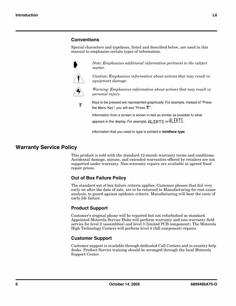
Conventions
Special characters and typefaces, listed and described below, are used in this manual to emphasize certain types of information.
Warranty Service PolicyThis product is sold with the standard 12-month warranty terms and conditions. Accidental damage, misuse, and extended warranties offered by retailers are not supported under warranty. Non-warranty repairs are available at agreed fixed repair prices.
Out of Box Failure Policy
The standard out of box failure criteria applies. Customer phones that fail very early on after the date of sale, are to be returned to Manufacturing for root-cause analysis, to guard against epidemic criteria. Manufacturing will bear the costs of early life failure.
Product Support
Customer’s original phone will be repaired but not refurbished as standard. Appointed Motorola Service Hubs will perform warranty and non-warranty field service for level 2 (assemblies) and level 3 (limited PCB component). The Motorola High Technology Centers will perform level 4 (full component) repairs.
Customer Support
Customer support is available through dedicated Call Centers and in-country help desks. Product Service training should be arranged through the local Motorola Support Center.
➧ Note: Emphasizes additional information pertinent to the subject matter.
G Caution: Emphasizes information about actions that may result in equipment damage.
E Warning: Emphasizes information about actions that may result in personal injury.
MKeys to be pressed are represented graphically. For example, instead of “Press
the Menu Key”, you will see “Press M”.
Information from a screen is shown in text as similar as possible to what
appears in the display. For example, ALERTS or ALERTS.
Information that you need to type is printed in boldface type
6809495A75-O October 14, 2005 7
Level 1 and 2 Service Manual Introduction
Parts ReplacementWhen ordering replacement parts or equipment, include the Motorola part number and description used in the service manual.
When the Motorola part number of a component is not known, use the product model number or other related major assembly along with a description of the related major assembly and of the component in question.
In the U.S.A., to contact Motorola, Inc. on your TTY, call: 800-793-7834.
Accessories and Aftermarket Division (AAD)
Order replacement parts, test equipment, and manuals from AAD.
U.S.A. Outside U.S.A.
Phone: 800-422-4210 Phone: 847-538-8023
FAX: 800-622-6210 FAX: 847-576-3023
Website: http://businessonline.motorola.com
EMEA
Phone: +49 461 803 1404
Website: http://emeaonline.motorola.com Asia
Phone: +65 648 62995
Website: http://asiaonline.motorola.com
8 October 14, 2005 6809495A75-O
Specifications L6
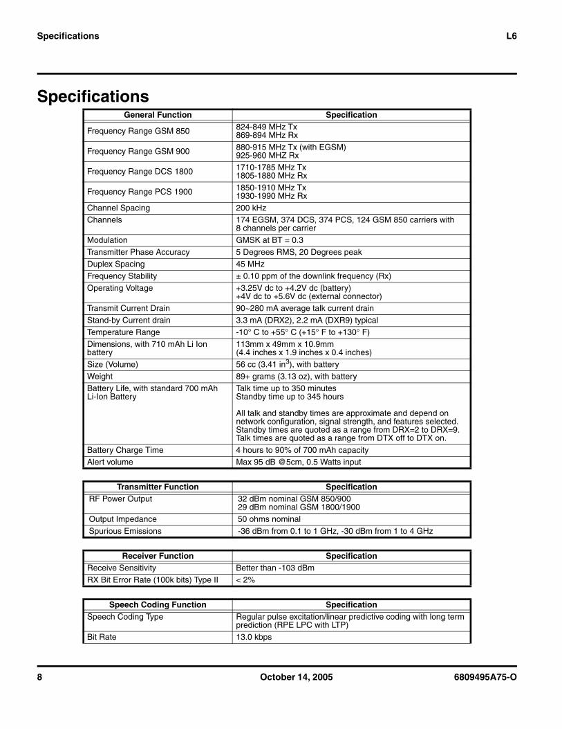
Specifications General Function Specification
Frequency Range GSM 850 824-849 MHz Tx869-894 MHz Rx
Frequency Range GSM 900 880-915 MHz Tx (with EGSM)925-960 MHZ Rx
Frequency Range DCS 1800 1710-1785 MHz Tx1805-1880 MHz Rx
Frequency Range PCS 1900 1850-1910 MHz Tx1930-1990 MHz Rx
Channel Spacing 200 kHzChannels 174 EGSM, 374 DCS, 374 PCS, 124 GSM 850 carriers with
8 channels per carrier
Modulation GMSK at BT = 0.3
Transmitter Phase Accuracy 5 Degrees RMS, 20 Degrees peakDuplex Spacing 45 MHz
Frequency Stability ± 0.10 ppm of the downlink frequency (Rx)
Operating Voltage +3.25V dc to +4.2V dc (battery)+4V dc to +5.6V dc (external connector)
Transmit Current Drain 90~280 mA average talk current drain
Stand-by Current drain 3.3 mA (DRX2), 2.2 mA (DXR9) typical
Temperature Range -10° C to +55° C (+15° F to +130° F)Dimensions, with 710 mAh Li Ion battery
113mm x 49mm x 10.9mm (4.4 inches x 1.9 inches x 0.4 inches)
Size (Volume) 56 cc (3.41 in3), with battery
Weight 89+ grams (3.13 oz), with batteryBattery Life, with standard 700 mAh Li-Ion Battery
Talk time up to 350 minutesStandby time up to 345 hours
All talk and standby times are approximate and depend on network configuration, signal strength, and features selected. Standby times are quoted as a range from DRX=2 to DRX=9. Talk times are quoted as a range from DTX off to DTX on.
Battery Charge Time 4 hours to 90% of 700 mAh capacity
Alert volume Max 95 dB @5cm, 0.5 Watts input
Transmitter Function SpecificationRF Power Output 32 dBm nominal GSM 850/900
29 dBm nominal GSM 1800/1900
Output Impedance 50 ohms nominal
Spurious Emissions -36 dBm from 0.1 to 1 GHz, -30 dBm from 1 to 4 GHz
Receiver Function SpecificationReceive Sensitivity Better than -103 dBm
RX Bit Error Rate (100k bits) Type II < 2%
Speech Coding Function SpecificationSpeech Coding Type Regular pulse excitation/linear predictive coding with long term
prediction (RPE LPC with LTP)
Bit Rate 13.0 kbps
6809495A75-O October 14, 2005 9
Level 1 and 2 Service Manual Specifications
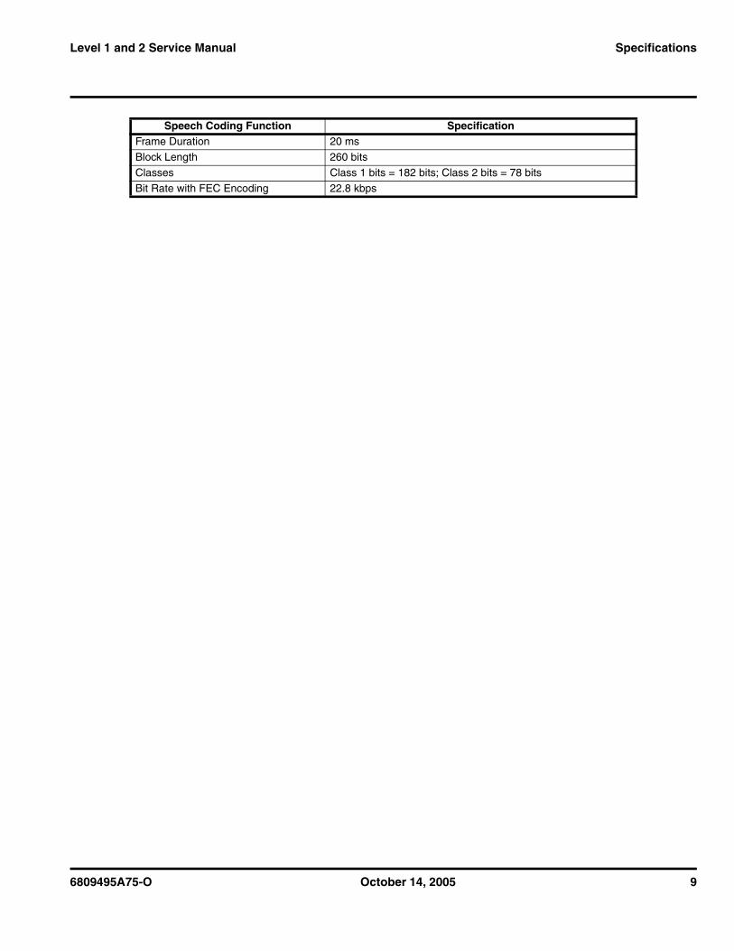
Frame Duration 20 ms
Block Length 260 bits
Classes Class 1 bits = 182 bits; Class 2 bits = 78 bits
Bit Rate with FEC Encoding 22.8 kbps
Speech Coding Function Specification
10 October 14, 2005 6809495A75-O
Product Overview L6
Product OverviewMotorola L6 mobile telephones feature Global System for Mobile communication (GSM) technology. The mobile telephone uses a simplified icon and Graphical User Interface (GUI) for easier operation, allow Short Message Service (SMS) text messaging, and include clock, alarm, datebook, and calculator personal management tools. The L6 telephones feature VibraCall vibrating alert and a wide selection of ring tones. The L6 tri-band phones allow roaming within the GSM 850, 1800, 1900 MHz PCS bands, or 900, 1800, 1900 MHz PCS bands depending on flexing.
L6 telephones support GPRS and SMS in addition to traditional circuit switched transport technologies.
The telephones are made of polycarbonate plastic with a metal enclosure. The display, camera, speaker, the 17-key keypad (not including navigation keys) , transceiver Printed-circuit Board (PCB), microphone, charger, headphone connectors, and power button are contained within the candy bar form-factor housing. The 700 mAh Lithium Ion (Li-Ion) battery provides up to 350 minutes of talk time with up to 345 hours of standby time1. These telephones feature a 128 x 160 pixel display.
FeaturesThe L6 telephones use advanced, self-contained, sealed, custom integrated circuits to perform the complex functions required for GSM communication. Aside from the space and weight advantage, microcircuits enhance basic reliability, simplify maintenance, and provide a variety of operational functions.
Features available in the L6 telephone include:• Bluetooth Class 2• Integrated handsfree speakerphone• Downloadable java apps, images & MP3 Polyphonic Ringtones • Picture Messaging with MMS• Wireless Village Instant Messaging• GPRS Class 10• Push to Talk over cellular with GPRS• Video playback (MPEG4/H.263)• Up to 10MB of end user embedded memory• PIM functionality with Picture Caller ID• Calling Line Identification• Video capture (7fps) and playback (15fps)• VGA camera with 4x zoom• Dynamic Idle (Motorola/4th Pass server)• 500 capacity phonebook
Upon receipt of a call, the calling party’s phone number is compared to the phonebook. If the number matches a phonebook entry, that name displays. If there
1. All talk and standby times are approximate and depend on network configuration, signal strength, and features selected. Standbytimes are quoted as a range from DRX=2 to DRX=9. Talk times are quoted as a range from DTX off to DTX on.
6809495A75-O October 14, 2005 11
Level 1 and 2 Service Manual Product Overview
is no phonebook entry, the incoming phone number displays. If no caller identification information is available, an incoming call message displays.
Personal Information Management
The L6 telephones contain a built-in datebook with alarm reminders, message center, and a phonebook.
Other Features
Detailed descriptions of other features available for the L6 wireless telephones are in the appropriate User’s Guide listed in the Related Publications section toward the end of this manual.
➧ User must subscribe to a caller line identification service through their service provider.
12 October 14, 2005 6809495A75-O
General Operation L6
General Operation
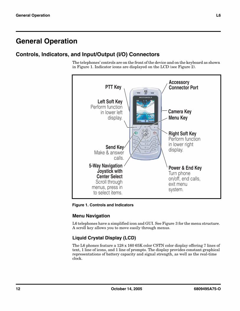
Controls, Indicators, and Input/Output (I/O) ConnectorsThe telephones’ controls are on the front of the device and on the keyboard as shown in Figure 1. Indicator icons are displayed on the LCD (see Figure 2).
Menu Navigation
L6 telephones have a simplified icon and GUI. See Figure 3 for the menu structure. A scroll key allows you to move easily through menus.
Liquid Crystal Display (LCD)
The L6 phones feature a 128 x 160 65K color CSTN color display offering 7 lines of text, 1 line of icons, and 1 line of prompts. The display provides constant graphical representations of battery capacity and signal strength, as well as the real-time clock.
Figure 1. Controls and Indicators
Left Soft KeyPerform function
in lower left display.
PTT Key
5-Way Navigation Joystick with Center SelectScroll through
menus, press in to select items.
Menu KeyCamera Key
Accessory Connector Port
Right Soft KeyPerform function in lower right display.
Power & End KeyTurn phone on/off, end calls, exit menu system.
Send KeyMake & answer
calls.
6809495A75-O October 14, 2005 13
Level 1 and 2 Service Manual General Operation
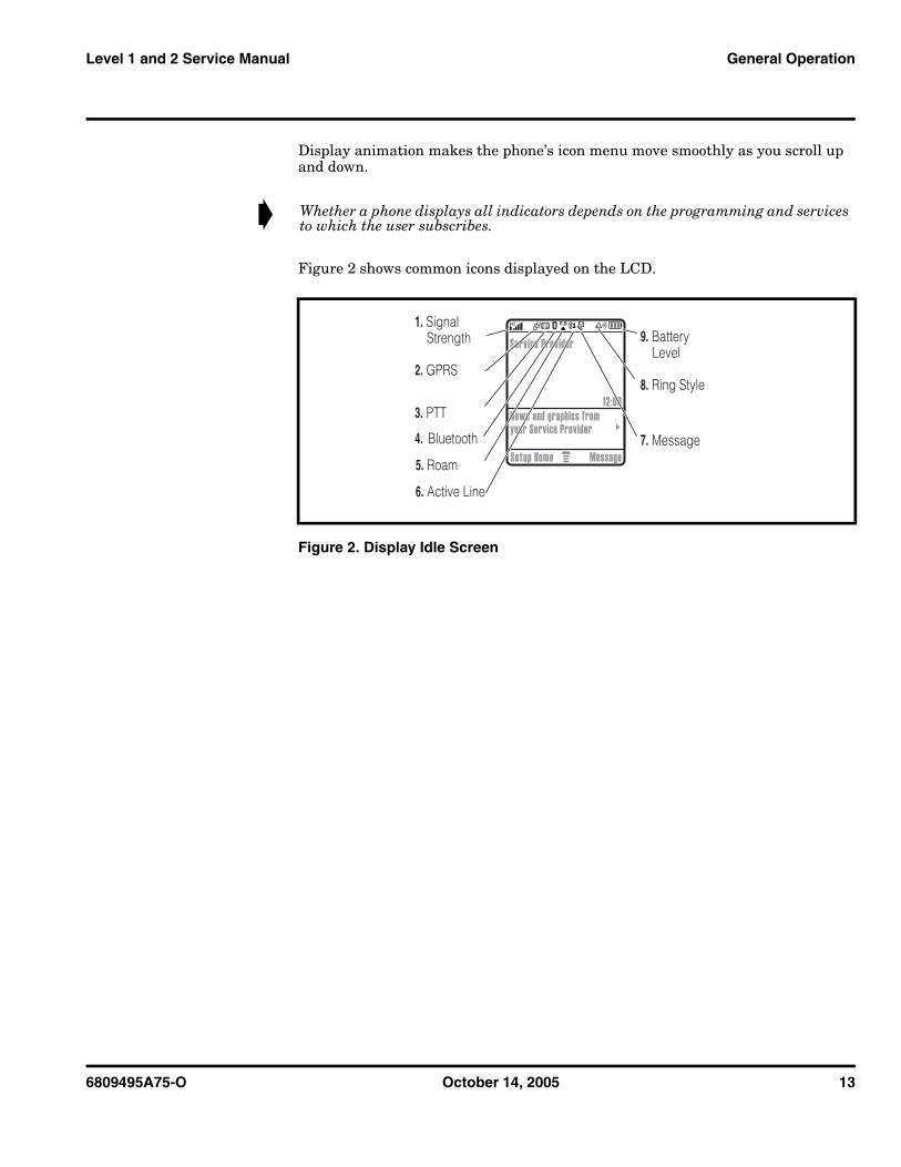
Display animation makes the phone’s icon menu move smoothly as you scroll up and down.
Figure 2 shows common icons displayed on the LCD.
➧ Whether a phone displays all indicators depends on the programming and services to which the user subscribes.
Figure 2. Display Idle Screen
E+U
040079b
6. Active Line
7. Message
8. Ring Style
9. Battery Level
5. Roam
3. PTT
2. GPRS
1. Signal Strength Service Provider
12:00News and graphics from your Service Provider
Setup Home Message4. Bluetooth
14 October 14, 2005 6809495A75-O
General Operation L6
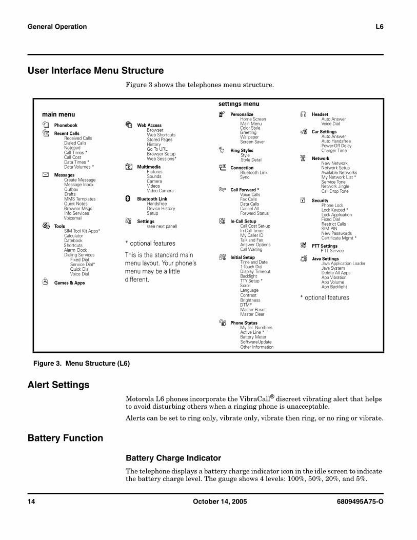
User Interface Menu StructureFigure 3 shows the telephones menu structure.
Alert SettingsMotorola L6 phones incorporate the VibraCall® discreet vibrating alert that helps to avoid disturbing others when a ringing phone is unacceptable.
Alerts can be set to ring only, vibrate only, vibrate then ring, or no ring or vibrate.
Battery Function
Battery Charge Indicator
The telephone displays a battery charge indicator icon in the idle screen to indicate the battery charge level. The gauge shows 4 levels: 100%, 50%, 20%, and 5%.
Figure 3. Menu Structure (L6)
main menu
n Phonebook
s Recent Calls Received Calls Dialed Calls Notepad Call Times * Call Cost
Data Times * Data Volumes *
e Messages Create Message Message Inbox Outbox Drafts
MMS Templates Quick Notes Browser Msgs
Info Services Voicemail
É Tools SIM Tool Kit Apps* Calculator Datebook Shortcuts Alarm Clock
Dialing Services Fixed Dial Service Dial* Quick Dial Voice Dial
Q Games & Apps
á Web Access Browser Web Shortcuts Stored Pages History Go To URL Browser Setup Web Sessions*
h Multimedia Pictures Sounds Camera Videos Video Camera
E Bluetooth Link Handsfree Device History Setup
w Settings (see next panel)
* optional features
This is the standard main menu layout. Your phone’s menu may be a little different.
settings menu
l Personalize Home Screen M
Color Styleain Menu
Greeting Wallpaper Screen Saver
t Ring Styles Style
Style Detail
L Connection Bluetooth Link Sync
H Call Forward * Voice Calls Fax Calls Data Calls Cancel All
Forward Status
U In-Call Setup Call Cost Set-up In-Call Timer My Caller ID Talk and Fax Answer Options Call Waiting
Z Initial Setup Time and Date 1-Touch Dial Display Timeout Backlight TTY Setup * Scroll Language
BrightnessContrast
DTMFMaster ResetMaster Clear
m Phone Status My Tel. Numbers
Active Line * Battery Meter
Software UpdateOther Information
S Headset Auto Answer Voice Dial
J Car Settings Auto Answer Auto Handsfree Power-Off Delay Charger Time
j Network New Network Network Setup Available Networks
My Network List * Service Tone
Call Drop Tone
u Security Phone Lock Lock Keypad * Lock Application Fixed Dial
Restrict Calls SIM PIN New Passwords
Certificate Mgmt *
6 PTT Settings P TT Service
c Java Settings Java Application Loader Java System Delete All Apps App Vibration App Volume
App Backlight
* optional features
Network Jingle
6809495A75-O October 14, 2005 15
Level 1 and 2 Service Manual General Operation
Battery Removal
Removing the battery causes the phone to shut down immediately and loose any pending work. For example, (partially entered phonebook entries or outgoing messages).
OperationFor detailed operating instructions, refer to the appropriate User’s Guide listed in the Related Publications section toward the end of this manual.
EAll batteries can cause property damage and/or bodily injury such as burns if a conductive material such as jewelry, keys, or beaded chains touch exposed terminals. The conductive material may complete an electrical circuit (short circuit) and become quite hot. Exercise care when handling any charged battery, particularly when placing it inside a pocket, purse, or other container with metal objects.
G If the battery is removed while receiving a message, the message is lost.
➧ To ensure proper memory retention, turn the phone OFF before removing the battery. Immediately replace the old battery with a fresh battery.
16 October 14, 2005 6809495A75-O
Tools and Test Equipment L6
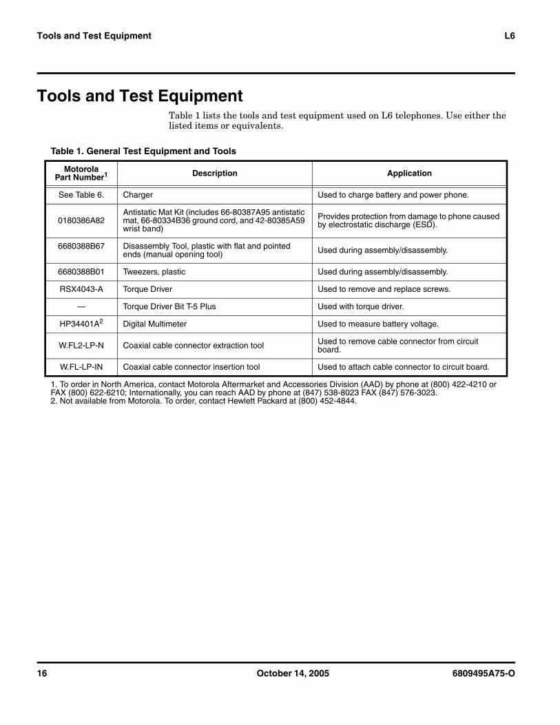
Tools and Test EquipmentTable 1 lists the tools and test equipment used on L6 telephones. Use either the listed items or equivalents.
Table 1. General Test Equipment and Tools
MotorolaPart Number1 Description Application
See Table 6. Charger Used to charge battery and power phone.
0180386A82Antistatic Mat Kit (includes 66-80387A95 antistatic mat, 66-80334B36 ground cord, and 42-80385A59 wrist band)
Provides protection from damage to phone caused by electrostatic discharge (ESD).
6680388B67 Disassembly Tool, plastic with flat and pointed ends (manual opening tool) Used during assembly/disassembly.
6680388B01 Tweezers, plastic Used during assembly/disassembly.
RSX4043-A Torque Driver Used to remove and replace screws.
— Torque Driver Bit T-5 Plus Used with torque driver.
HP34401A2 Digital Multimeter Used to measure battery voltage.
W.FL2-LP-N Coaxial cable connector extraction tool Used to remove cable connector from circuit board.
W.FL-LP-IN Coaxial cable connector insertion tool Used to attach cable connector to circuit board.
1. To order in North America, contact Motorola Aftermarket and Accessories Division (AAD) by phone at (800) 422-4210 or FAX (800) 622-6210; Internationally, you can reach AAD by phone at (847) 538-8023 FAX (847) 576-3023.2. Not available from Motorola. To order, contact Hewlett Packard at (800) 452-4844.
1 and 26809495A75-OL6
6809495A75-O October 14, 2005 17
Level 1 and 2 Service Manual Disassembly
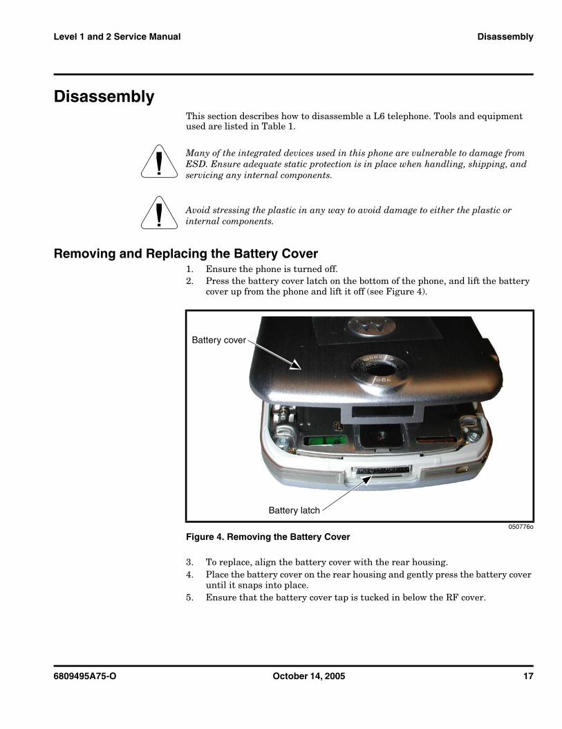
DisassemblyThis section describes how to disassemble a L6 telephone. Tools and equipment used are listed in Table 1.
Removing and Replacing the Battery Cover1. Ensure the phone is turned off.2. Press the battery cover latch on the bottom of the phone, and lift the battery
cover up from the phone and lift it off (see Figure 4).
3. To replace, align the battery cover with the rear housing. 4. Place the battery cover on the rear housing and gently press the battery cover
until it snaps into place.5. Ensure that the battery cover tap is tucked in below the RF cover.
G Many of the integrated devices used in this phone are vulnerable to damage from ESD. Ensure adequate static protection is in place when handling, shipping, and servicing any internal components.
G Avoid stressing the plastic in any way to avoid damage to either the plastic or internal components.
050776o
Figure 4. Removing the Battery Cover
Battery latch
Battery cover
18 October 14, 2005 6809495A75-O
Disassembly L6
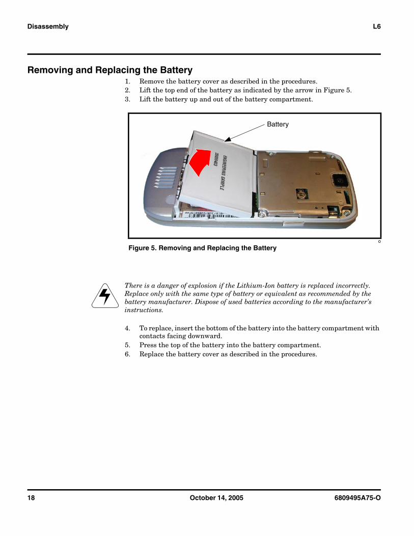
Removing and Replacing the Battery1. Remove the battery cover as described in the procedures.2. Lift the top end of the battery as indicated by the arrow in Figure 5.3. Lift the battery up and out of the battery compartment.
4. To replace, insert the bottom of the battery into the battery compartment with contacts facing downward.
5. Press the top of the battery into the battery compartment.6. Replace the battery cover as described in the procedures.
o
Figure 5. Removing and Replacing the Battery
EThere is a danger of explosion if the Lithium-Ion battery is replaced incorrectly. Replace only with the same type of battery or equivalent as recommended by the battery manufacturer. Dispose of used batteries according to the manufacturer’s instructions.
Battery
6809495A75-O October 14, 2005 19
Level 1 and 2 Service Manual Disassembly
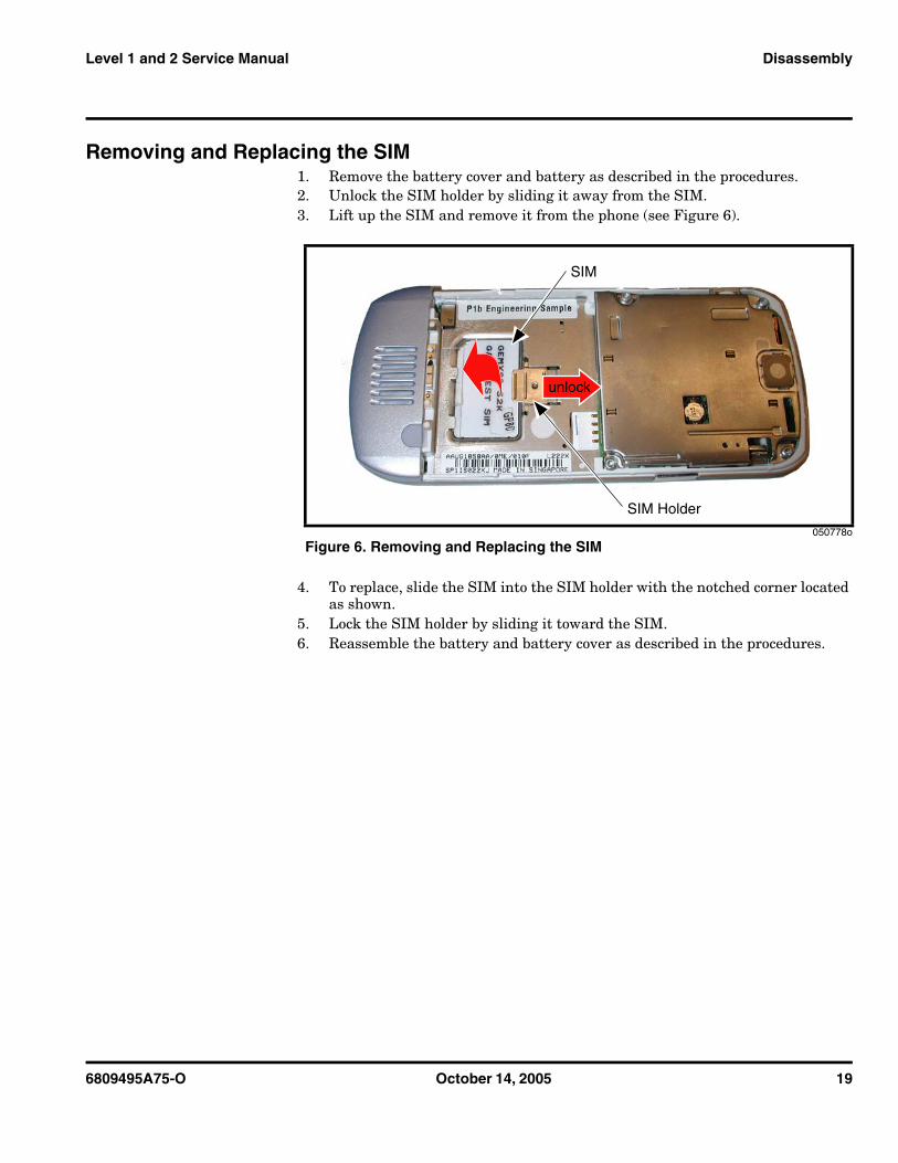
Removing and Replacing the SIM1. Remove the battery cover and battery as described in the procedures.2. Unlock the SIM holder by sliding it away from the SIM.3. Lift up the SIM and remove it from the phone (see Figure 6).
4. To replace, slide the SIM into the SIM holder with the notched corner located as shown.
5. Lock the SIM holder by sliding it toward the SIM.6. Reassemble the battery and battery cover as described in the procedures.
050778o
Figure 6. Removing and Replacing the SIM
SIM
SIM Holder
unlock
20 October 14, 2005 6809495A75-O
Disassembly L6
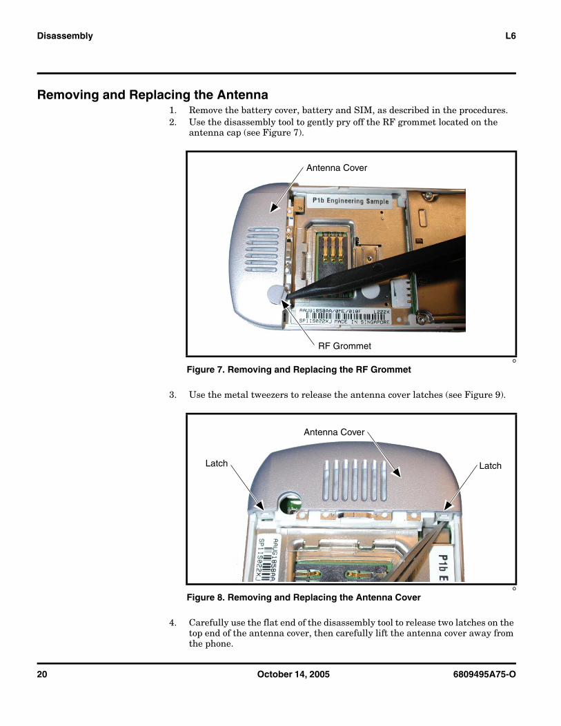
Removing and Replacing the Antenna1. Remove the battery cover, battery and SIM, as described in the procedures.2. Use the disassembly tool to gently pry off the RF grommet located on the
antenna cap (see Figure 7).
3. Use the metal tweezers to release the antenna cover latches (see Figure 9).
4. Carefully use the flat end of the disassembly tool to release two latches on the top end of the antenna cover, then carefully lift the antenna cover away from the phone.
o
Figure 7. Removing and Replacing the RF Grommet
o
Figure 8. Removing and Replacing the Antenna Cover
Antenna Cover
RF Grommet
LatchLatch
Antenna Cover
6809495A75-O October 14, 2005 21
Level 1 and 2 Service Manual Disassembly
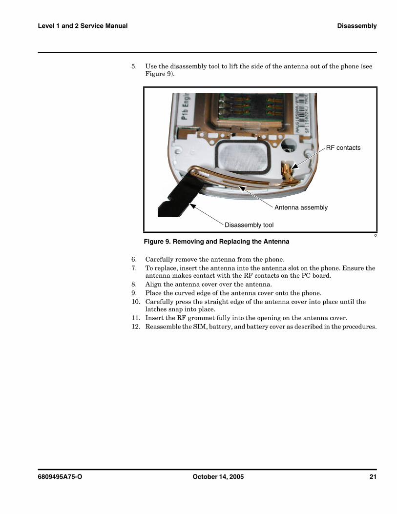
5. Use the disassembly tool to lift the side of the antenna out of the phone (see Figure 9).
6. Carefully remove the antenna from the phone.7. To replace, insert the antenna into the antenna slot on the phone. Ensure the
antenna makes contact with the RF contacts on the PC board.8. Align the antenna cover over the antenna.9. Place the curved edge of the antenna cover onto the phone.10. Carefully press the straight edge of the antenna cover into place until the
latches snap into place.11. Insert the RF grommet fully into the opening on the antenna cover.12. Reassemble the SIM, battery, and battery cover as described in the procedures.
o
Figure 9. Removing and Replacing the Antenna
Antenna assembly
RF contacts
Disassembly tool
22 October 14, 2005 6809495A75-O
Disassembly L6
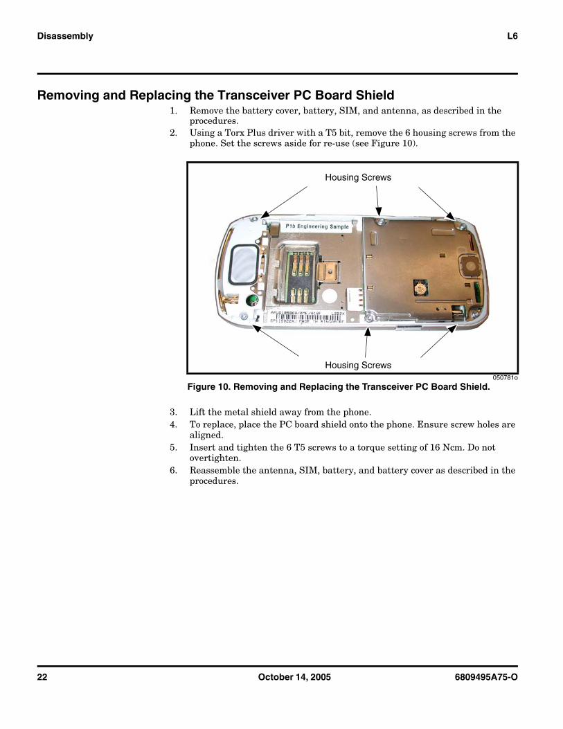
Removing and Replacing the Transceiver PC Board Shield1. Remove the battery cover, battery, SIM, and antenna, as described in the
procedures.2. Using a Torx Plus driver with a T5 bit, remove the 6 housing screws from the
phone. Set the screws aside for re-use (see Figure 10).
3. Lift the metal shield away from the phone.4. To replace, place the PC board shield onto the phone. Ensure screw holes are
aligned. 5. Insert and tighten the 6 T5 screws to a torque setting of 16 Ncm. Do not
overtighten.6. Reassemble the antenna, SIM, battery, and battery cover as described in the
procedures.
050781o
Figure 10. Removing and Replacing the Transceiver PC Board Shield.
Housing Screws
Housing Screws
6809495A75-O October 14, 2005 23
Level 1 and 2 Service Manual Disassembly
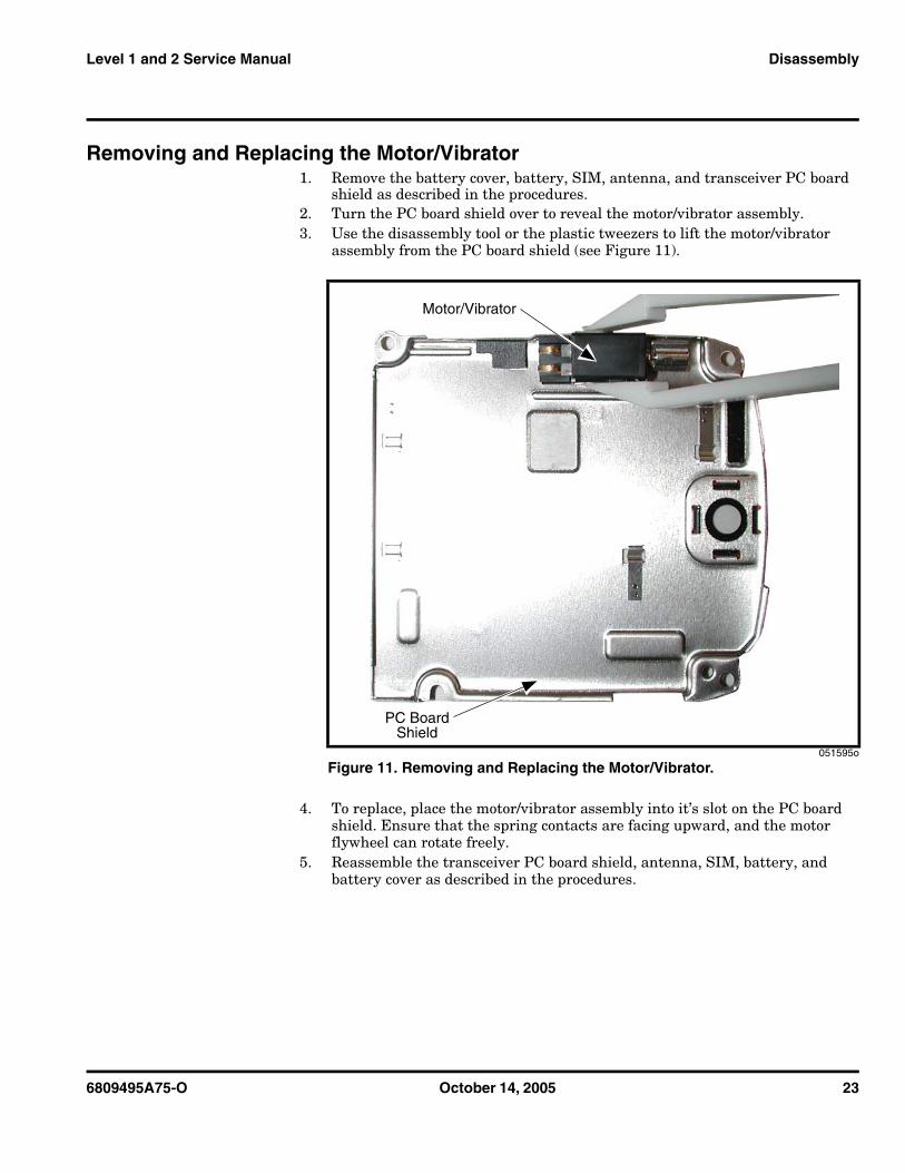
Removing and Replacing the Motor/Vibrator1. Remove the battery cover, battery, SIM, antenna, and transceiver PC board
shield as described in the procedures.2. Turn the PC board shield over to reveal the motor/vibrator assembly.3. Use the disassembly tool or the plastic tweezers to lift the motor/vibrator
assembly from the PC board shield (see Figure 11).
4. To replace, place the motor/vibrator assembly into it’s slot on the PC board shield. Ensure that the spring contacts are facing upward, and the motor flywheel can rotate freely.
5. Reassemble the transceiver PC board shield, antenna, SIM, battery, and battery cover as described in the procedures.
051595o
Figure 11. Removing and Replacing the Motor/Vibrator.
Motor/Vibrator
PC BoardShield
24 October 14, 2005 6809495A75-O
Disassembly L6
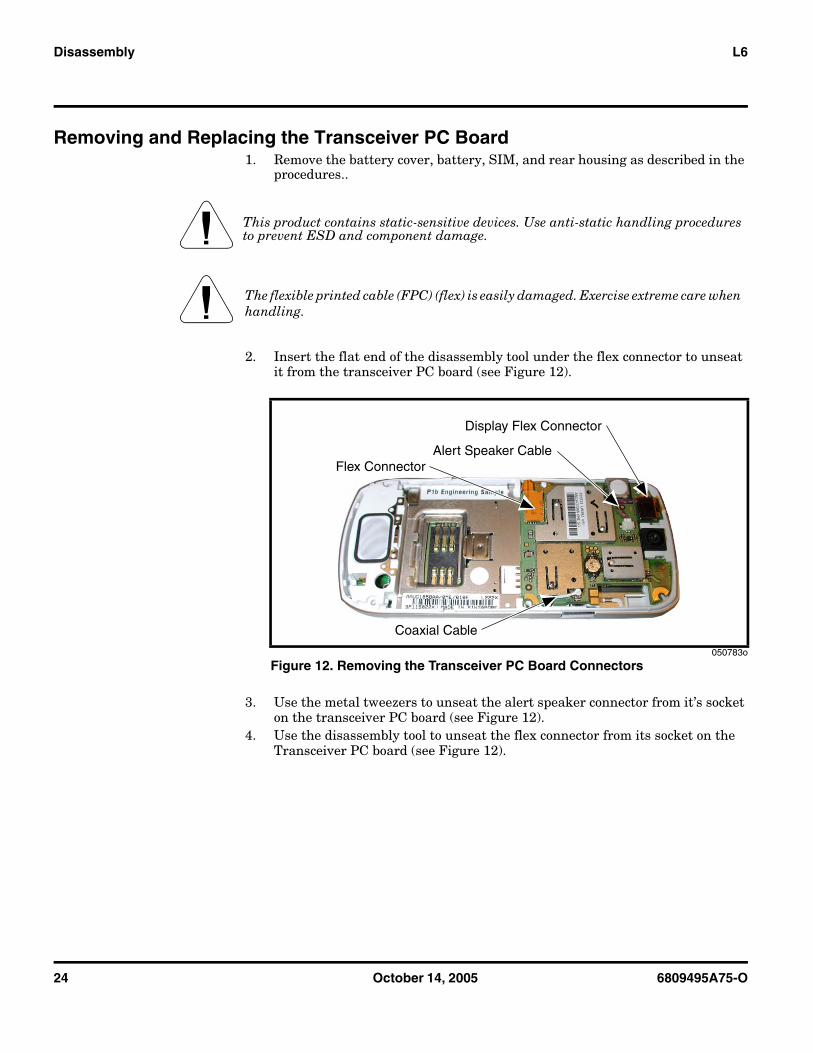
Removing and Replacing the Transceiver PC Board1. Remove the battery cover, battery, SIM, and rear housing as described in the
procedures..
2. Insert the flat end of the disassembly tool under the flex connector to unseat it from the transceiver PC board (see Figure 12).
3. Use the metal tweezers to unseat the alert speaker connector from it’s socket on the transceiver PC board (see Figure 12).
4. Use the disassembly tool to unseat the flex connector from its socket on the Transceiver PC board (see Figure 12).
G This product contains static-sensitive devices. Use anti-static handling procedures to prevent ESD and component damage.
G The flexible printed cable (FPC) (flex) is easily damaged. Exercise extreme care when handling.
050783o
Figure 12. Removing the Transceiver PC Board Connectors
Flex ConnectorAlert Speaker Cable
Coaxial Cable
Display Flex Connector
6809495A75-O October 14, 2005 25
Level 1 and 2 Service Manual Disassembly
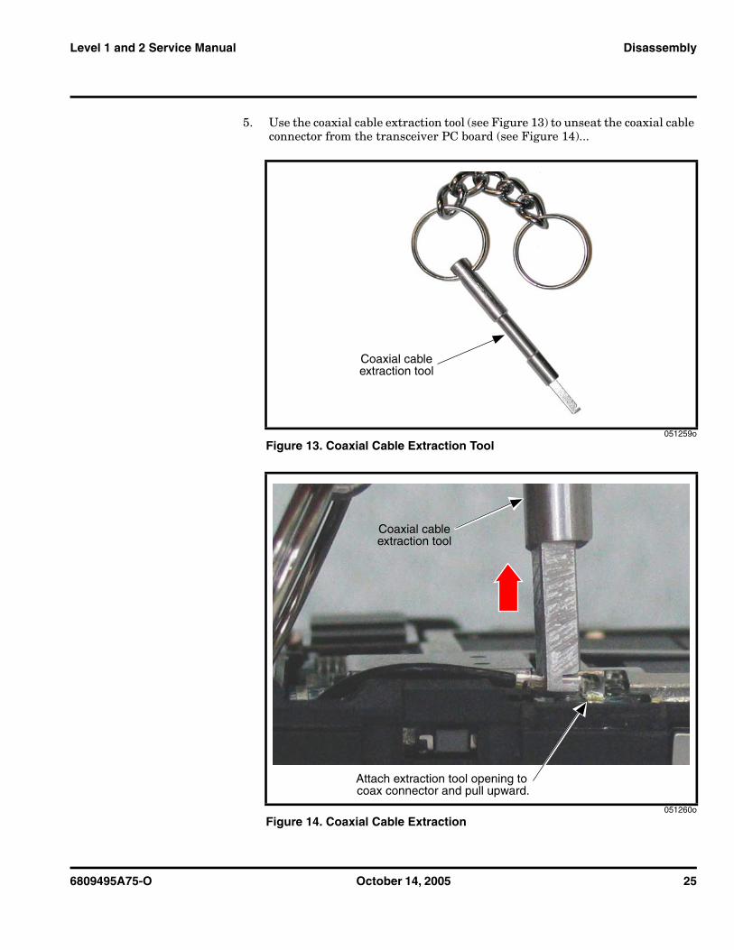
5. Use the coaxial cable extraction tool (see Figure 13) to unseat the coaxial cable connector from the transceiver PC board (see Figure 14)...
051259o
Figure 13. Coaxial Cable Extraction Tool
051260o
Figure 14. Coaxial Cable Extraction
Coaxial cableextraction tool
Coaxial cableextraction tool
Attach extraction tool opening to coax connector and pull upward.
26 October 14, 2005 6809495A75-O
Disassembly L6
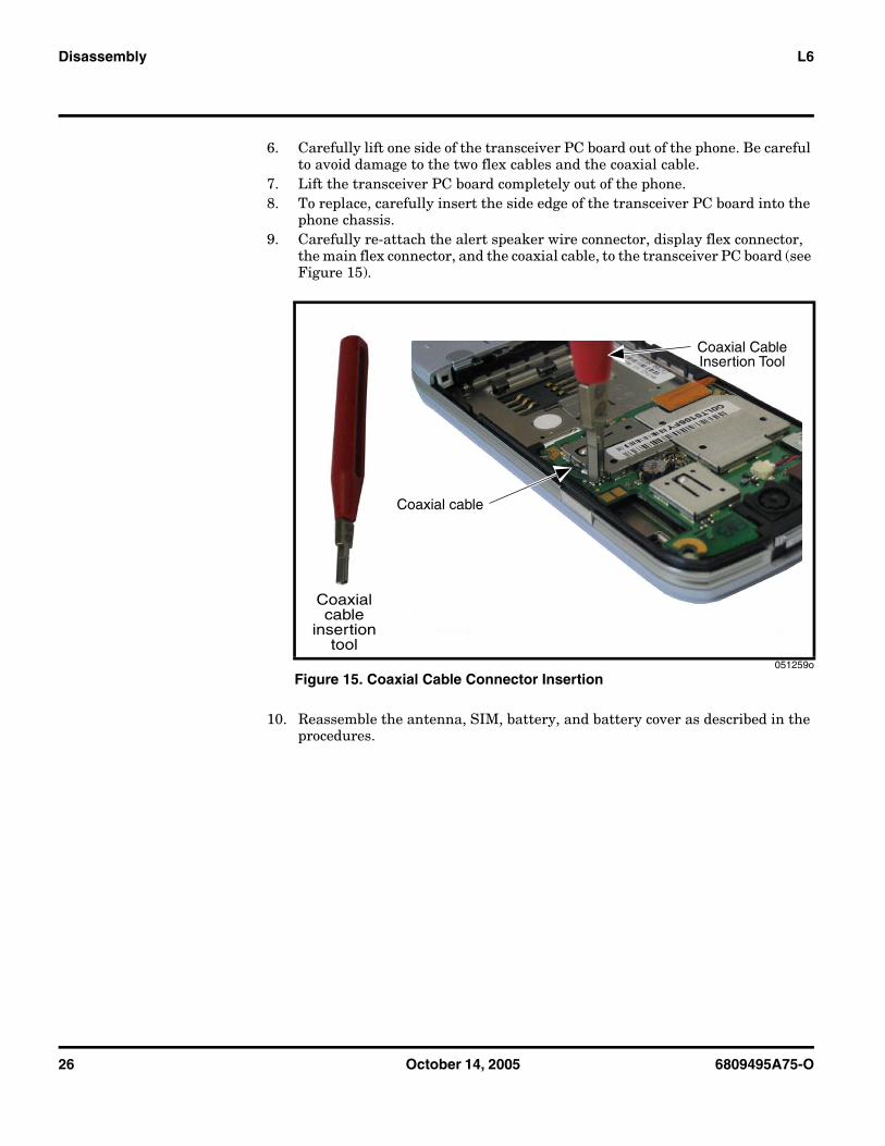
6. Carefully lift one side of the transceiver PC board out of the phone. Be careful to avoid damage to the two flex cables and the coaxial cable.
7. Lift the transceiver PC board completely out of the phone.8. To replace, carefully insert the side edge of the transceiver PC board into the
phone chassis.9. Carefully re-attach the alert speaker wire connector, display flex connector,
the main flex connector, and the coaxial cable, to the transceiver PC board (see Figure 15).
10. Reassemble the antenna, SIM, battery, and battery cover as described in the procedures.
051259o
Figure 15. Coaxial Cable Connector Insertion
Coaxial cable
Coaxial CableInsertion Tool
Coaxialcable
insertiontool
6809495A75-O October 14, 2005 27
Level 1 and 2 Service Manual Disassembly
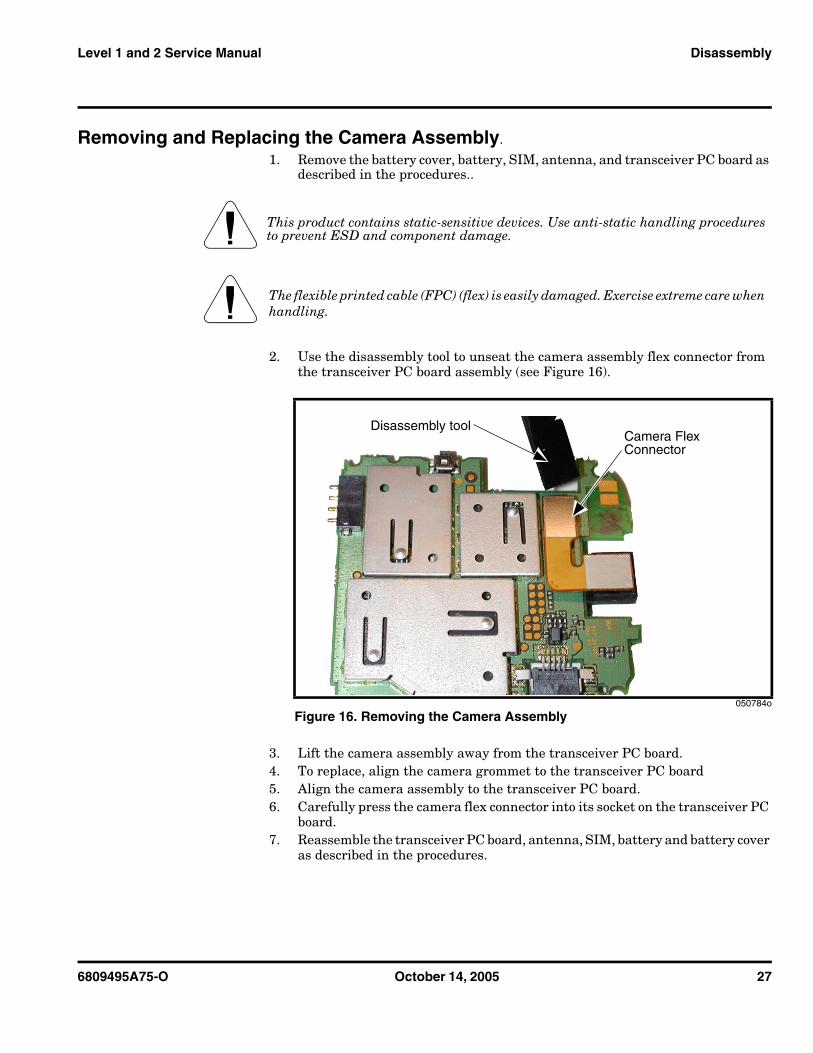
Removing and Replacing the Camera Assembly.
1. Remove the battery cover, battery, SIM, antenna, and transceiver PC board as described in the procedures..
2. Use the disassembly tool to unseat the camera assembly flex connector from the transceiver PC board assembly (see Figure 16).
3. Lift the camera assembly away from the transceiver PC board.4. To replace, align the camera grommet to the transceiver PC board5. Align the camera assembly to the transceiver PC board.6. Carefully press the camera flex connector into its socket on the transceiver PC
board.7. Reassemble the transceiver PC board, antenna, SIM, battery and battery cover
as described in the procedures.
G This product contains static-sensitive devices. Use anti-static handling procedures to prevent ESD and component damage.
G The flexible printed cable (FPC) (flex) is easily damaged. Exercise extreme care when handling.
050784o
Figure 16. Removing the Camera Assembly
Disassembly toolCamera Flex Connector
28 October 14, 2005 6809495A75-O
Disassembly L6
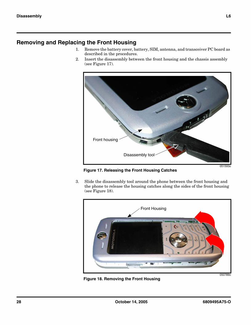
Removing and Replacing the Front Housing1. Remove the battery cover, battery, SIM, antenna, and transceiver PC board as
described in the procedures.2. Insert the disassembly between the front housing and the chassis assembly
(see Figure 17).
3. Slide the disassembly tool around the phone between the front housing and the phone to release the housing catches along the sides of the front housing (see Figure 18).
051593o
Figure 17. Releasing the Front Housing Catches
050789o
Figure 18. Removing the Front Housing
Front housing
Disassembly tool
Front Housing
6809495A75-O October 14, 2005 29
Level 1 and 2 Service Manual Disassembly
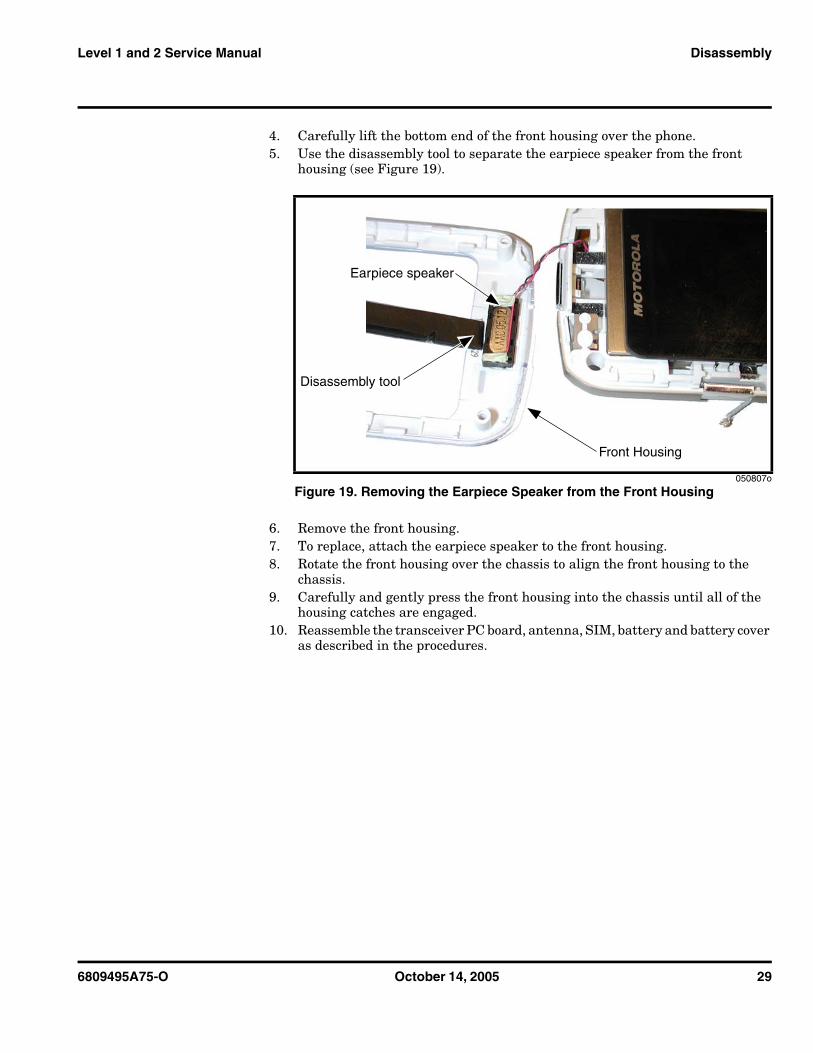
4. Carefully lift the bottom end of the front housing over the phone.5. Use the disassembly tool to separate the earpiece speaker from the front
housing (see Figure 19).
6. Remove the front housing.7. To replace, attach the earpiece speaker to the front housing.8. Rotate the front housing over the chassis to align the front housing to the
chassis.9. Carefully and gently press the front housing into the chassis until all of the
housing catches are engaged.10. Reassemble the transceiver PC board, antenna, SIM, battery and battery cover
as described in the procedures.
050807o
Figure 19. Removing the Earpiece Speaker from the Front Housing
Earpiece speaker
Disassembly tool
Front Housing
30 October 14, 2005 6809495A75-O
Disassembly L6
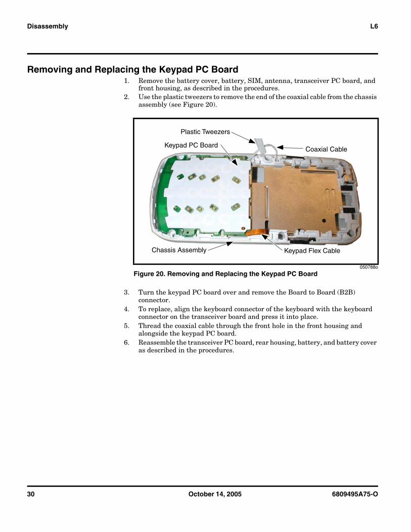
Removing and Replacing the Keypad PC Board1. Remove the battery cover, battery, SIM, antenna, transceiver PC board, and
front housing, as described in the procedures.2. Use the plastic tweezers to remove the end of the coaxial cable from the chassis
assembly (see Figure 20).
3. Turn the keypad PC board over and remove the Board to Board (B2B) connector.
4. To replace, align the keyboard connector of the keyboard with the keyboard connector on the transceiver board and press it into place.
5. Thread the coaxial cable through the front hole in the front housing and alongside the keypad PC board.
6. Reassemble the transceiver PC board, rear housing, battery, and battery cover as described in the procedures.
050788o
Figure 20. Removing and Replacing the Keypad PC Board
Coaxial Cable
Keypad Flex Cable
Plastic Tweezers
Chassis Assembly
Keypad PC Board
6809495A75-O October 14, 2005 31
Level 1 and 2 Service Manual Disassembly
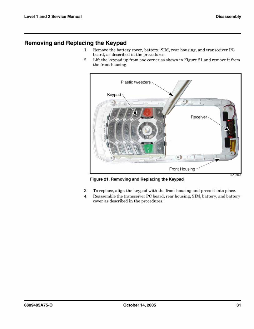
Removing and Replacing the Keypad1. Remove the battery cover, battery, SIM, rear housing, and transceiver PC
board, as described in the procedures.2. Lift the keypad up from one corner as shown in Figure 21 and remove it from
the front housing.
3. To replace, align the keypad with the front housing and press it into place.4. Reassemble the transceiver PC board, rear housing, SIM, battery, and battery
cover as described in the procedures.
051594o
Figure 21. Removing and Replacing the Keypad
Keypad
Plastic tweezers
Receiver
Front Housing
32 October 14, 2005 6809495A75-O
Disassembly L6
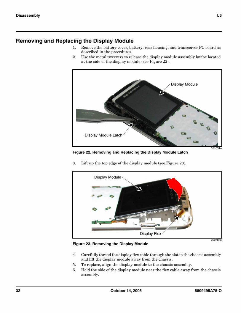
Removing and Replacing the Display Module 1. Remove the battery cover, battery, rear housing, and transceiver PC board as
described in the procedures.2. Use the metal tweezers to release the display module assembly latche located
at the side of the display module (see Figure 22).
3. Lift up the top edge of the display module (see Figure 23).
4. Carefully thread the display flex cable through the slot in the chassis assembly and lift the display module away from the chassis.
5. To replace, align the display module to the chassis assembly.6. Hold the side of the display module near the flex cable away from the chassis
assembly.
051631o
Figure 22. Removing and Replacing the Display Module Latch
050787o
Figure 23. Removing the Display Module
Display Module Latch
Display Module
Display Module
Display Flex
6809495A75-O October 14, 2005 33
Level 1 and 2 Service Manual Disassembly
7. Carefully thread the display flex connector through the opening on the chassis assembly.
8. Lower the display module fully onto the chassis assembly and gently press it into place.
9. Reassemble the transceiver PC board, antenna, SIM, battery, and battery cover as described in the procedures.
34 October 14, 2005 6809495A75-O
Subscriber Identity Module (SIM) and Identification Label L6
Subscriber Identity Module (SIM) and Identification Label
SIMA SIM is required to access the existing local GSM network, or remote networks when traveling (if a roaming agreement has been made with the provider).
The SIM card contains:• All the data necessary to access GSM services• The ability to store user information such as phone numbers• All information required by the network provider to provide access to the net-
work
IdentificationEach Motorola GSM phone is labeled with a variety of identifying numbers. The following information describes the current identifying labels.
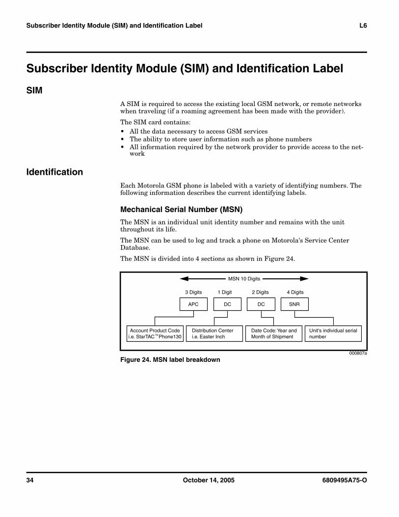
Mechanical Serial Number (MSN)
The MSN is an individual unit identity number and remains with the unit throughout its life.
The MSN can be used to log and track a phone on Motorola's Service Center Database.
The MSN is divided into 4 sections as shown in Figure 24.
000807a
Figure 24. MSN label breakdown
MSN 10 Digits
3 Digits 1 Digit 2 Digits 4 Digits
APC DC DC SNR
Account Product Codei.e. StarTAC Phone130
Distribution Centeri.e. Easter Inch
Date Code: Year andMonth of Shipment
Unit's individual serialnumberTM
6809495A75-O October 14, 2005 35
Level 1 and 2 Service Manual Subscriber Identity Module (SIM) and Identification Label
International Mobile Station Equipment Identity (IMEI)
The International Mobile station Equipment Identity (IMEI) number is an individual number unique to the PCB and is stored within the unit's memory.
The IMEI uniquely identifies an individual mobile station and thereby provides a means for controlling access to GSM networks based on mobile station types or individual units. The full IMEI structure is listed in Table 2.
Where
TAC Type Allocation Code, formerly known as Type Approval Code
NN Reporting body identifier
XXXX Type Identifier
YY YY is set to 00 from 01/01/2003 until 31/03/2004
ZZZZZZ Individual unit serial number
A Phase 1 = 0. Phase 2 = check digit defined as a function of all other IMEI digits
Other label number configurations present are: • TRANSCEIVER NUMBER: Identifies the product type. Normally the SWF
number. (i.e. V100).• PACKAGE NUMBER: Identifies the equipment type, mode, and language in
which the product is shipped.
Table 2. IMEI Number Breakdown
TAC Serial Number Check Digit
NNXXXX YY ZZZZZZ A
36 October 14, 2005 6809495A75-O
Telephone Identification L6
Telephone Identification
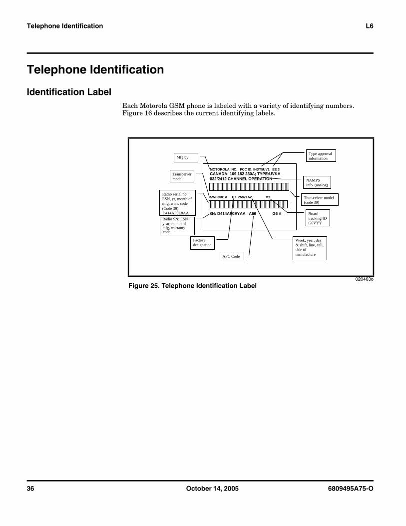
Identification LabelEach Motorola GSM phone is labeled with a variety of identifying numbers. Figure 16 describes the current identifying labels.
020463o
Figure 25. Telephone Identification Label
MOTOROLA INC. FCC ID: IHDT5UV1 EE 3 CANADA: 109 182 230A; TYPE:UVKA 832/2412 CHANNEL OPERATION
SWF3001A H7 25821A2 VY
SN: D414AF0EYAA A56 G6 #
Mfg by Type approval information
NAMPS info. (analog)
Transceiver model (code 39)
Transceiver model
Board tracking ID G6VYY
Radio SN: ESN+ year, month of mfg, warranty code
APC Code
Radio serial no. : ESN, yr, month of mfg, warr. code (Code 39) D414AF0E8AA
Week, year, day & shift, line, cell, side of manufacture
Factory designation
6809495A75-O October 14, 2005 37
Level 1 and 2 Service Manual Troubleshooting
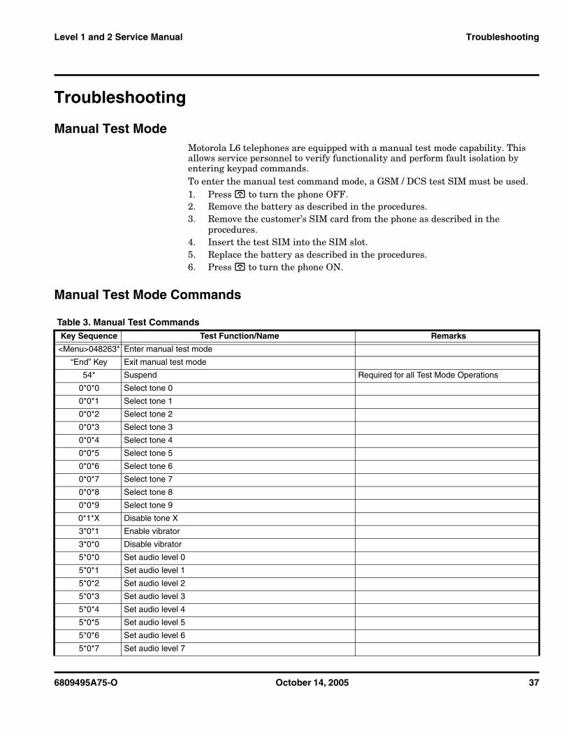
Troubleshooting
Manual Test ModeMotorola L6 telephones are equipped with a manual test mode capability. This allows service personnel to verify functionality and perform fault isolation by entering keypad commands. To enter the manual test command mode, a GSM / DCS test SIM must be used.1. Press u to turn the phone OFF.2. Remove the battery as described in the procedures.3. Remove the customer’s SIM card from the phone as described in the
procedures.4. Insert the test SIM into the SIM slot.5. Replace the battery as described in the procedures.6. Press u to turn the phone ON.
Manual Test Mode Commands
Table 3. Manual Test Commands Key Sequence Test Function/Name Remarks
<Menu>048263* Enter manual test mode
“End” Key Exit manual test mode
54* Suspend Required for all Test Mode Operations
0*0*0 Select tone 0
0*0*1 Select tone 1
0*0*2 Select tone 2
0*0*3 Select tone 3
0*0*4 Select tone 4
0*0*5 Select tone 5
0*0*6 Select tone 6
0*0*7 Select tone 7
0*0*8 Select tone 8
0*0*9 Select tone 9
0*1*X Disable tone X
3*0*1 Enable vibrator
3*0*0 Disable vibrator
5*0*0 Set audio level 0
5*0*1 Set audio level 1
5*0*2 Set audio level 2
5*0*3 Set audio level 3
5*0*4 Set audio level 4
5*0*5 Set audio level 5
5*0*6 Set audio level 6
5*0*7 Set audio level 7
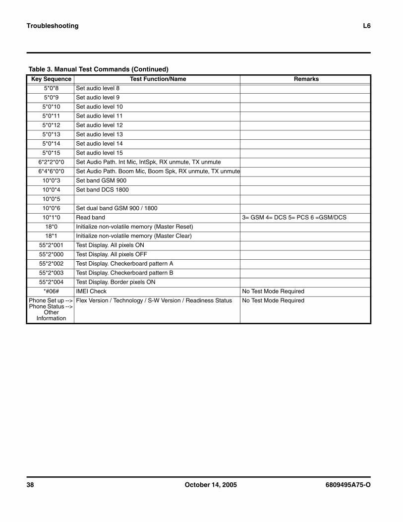
38 October 14, 2005 6809495A75-O
Troubleshooting L6
5*0*8 Set audio level 8
5*0*9 Set audio level 9
5*0*10 Set audio level 10
5*0*11 Set audio level 11
5*0*12 Set audio level 12
5*0*13 Set audio level 13
5*0*14 Set audio level 14
5*0*15 Set audio level 15
6*2*2*0*0 Set Audio Path. Int Mic, IntSpk, RX unmute, TX unmute
6*4*6*0*0 Set Audio Path. Boom Mic, Boom Spk, RX unmute, TX unmute
10*0*3 Set band GSM 900
10*0*4 Set band DCS 1800
10*0*5
10*0*6 Set dual band GSM 900 / 1800
10*1*0 Read band 3= GSM 4= DCS 5= PCS 6 =GSM/DCS
18*0 Initialize non-volatile memory (Master Reset)
18*1 Initialize non-volatile memory (Master Clear)
55*2*001 Test Display. All pixels ON
55*2*000 Test Display. All pixels OFF
55*2*002 Test Display. Checkerboard pattern A
55*2*003 Test Display. Checkerboard pattern B
55*2*004 Test Display. Border pixels ON
*#06# IMEI Check No Test Mode Required
Phone Set up --> Phone Status -->
Other Information
Flex Version / Technology / S-W Version / Readiness Status No Test Mode Required
Table 3. Manual Test Commands (Continued) Key Sequence Test Function/Name Remarks
6809495A75-O October 14, 2005 39
Level 1 and 2 Service Manual Troubleshooting
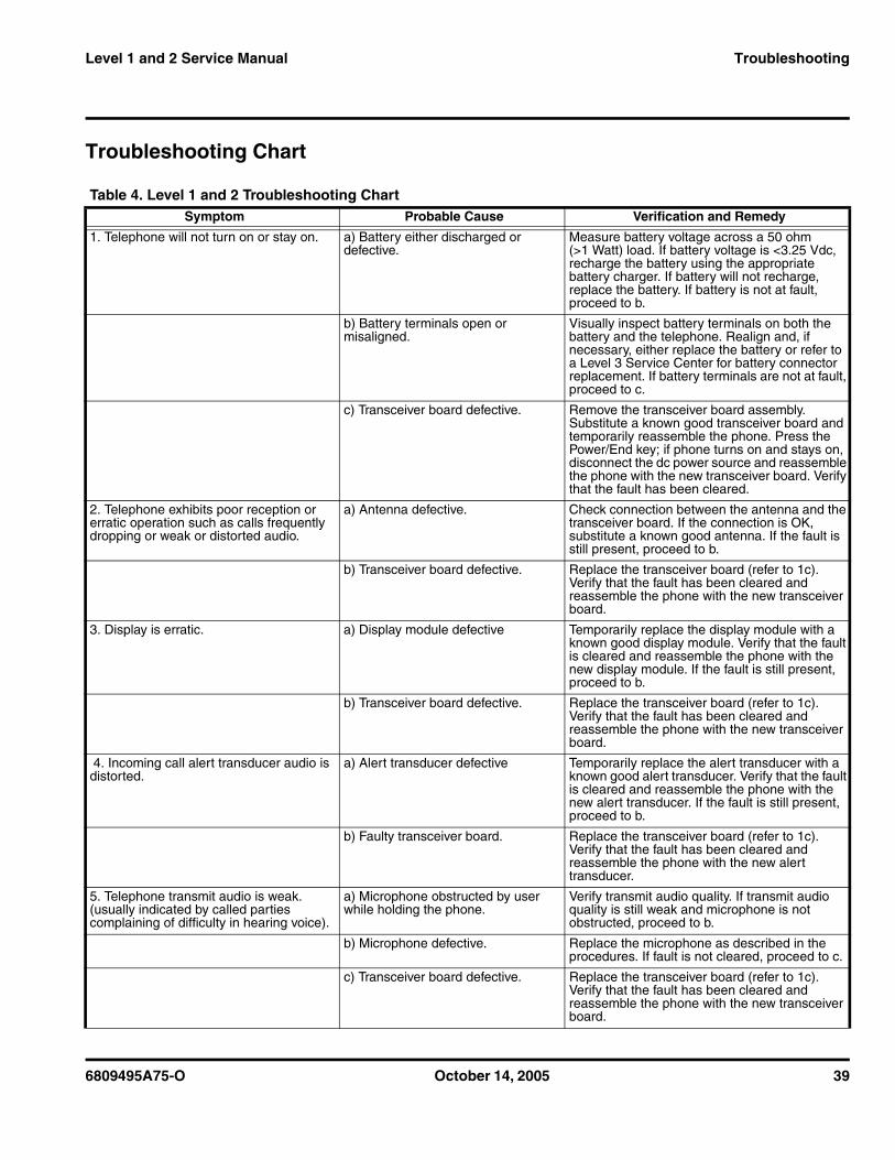
Troubleshooting Chart
Table 4. Level 1 and 2 Troubleshooting Chart Symptom Probable Cause Verification and Remedy
1. Telephone will not turn on or stay on. a) Battery either discharged or defective.
Measure battery voltage across a 50 ohm (>1 Watt) load. If battery voltage is <3.25 Vdc, recharge the battery using the appropriate battery charger. If battery will not recharge, replace the battery. If battery is not at fault, proceed to b.
b) Battery terminals open or misaligned.
Visually inspect battery terminals on both the battery and the telephone. Realign and, if necessary, either replace the battery or refer to a Level 3 Service Center for battery connector replacement. If battery terminals are not at fault, proceed to c.
c) Transceiver board defective. Remove the transceiver board assembly. Substitute a known good transceiver board and temporarily reassemble the phone. Press the Power/End key; if phone turns on and stays on, disconnect the dc power source and reassemble the phone with the new transceiver board. Verify that the fault has been cleared.
2. Telephone exhibits poor reception or erratic operation such as calls frequently dropping or weak or distorted audio.
a) Antenna defective. Check connection between the antenna and the transceiver board. If the connection is OK, substitute a known good antenna. If the fault is still present, proceed to b.
b) Transceiver board defective. Replace the transceiver board (refer to 1c). Verify that the fault has been cleared and reassemble the phone with the new transceiver board.
3. Display is erratic. a) Display module defective Temporarily replace the display module with a known good display module. Verify that the fault is cleared and reassemble the phone with the new display module. If the fault is still present, proceed to b.
b) Transceiver board defective. Replace the transceiver board (refer to 1c). Verify that the fault has been cleared and reassemble the phone with the new transceiver board.
4. Incoming call alert transducer audio is distorted.
a) Alert transducer defective Temporarily replace the alert transducer with a known good alert transducer. Verify that the fault is cleared and reassemble the phone with the new alert transducer. If the fault is still present, proceed to b.
b) Faulty transceiver board. Replace the transceiver board (refer to 1c). Verify that the fault has been cleared and reassemble the phone with the new alert transducer.
5. Telephone transmit audio is weak. (usually indicated by called parties complaining of difficulty in hearing voice).
a) Microphone obstructed by user while holding the phone.
Verify transmit audio quality. If transmit audio quality is still weak and microphone is not obstructed, proceed to b.
b) Microphone defective. Replace the microphone as described in the procedures. If fault is not cleared, proceed to c.
c) Transceiver board defective. Replace the transceiver board (refer to 1c). Verify that the fault has been cleared and reassemble the phone with the new transceiver board.
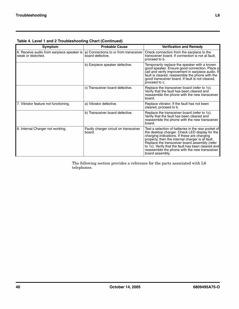
40 October 14, 2005 6809495A75-O
Troubleshooting L6
The following section provides a reference for the parts associated with L6 telephones.
6. Receive audio from earpiece speaker is weak or distorted.
a) Connections to or from transceiver board defective.
Check connection from the earpiece to the transceiver board. If connection is not at fault, proceed to b.
b) Earpiece speaker defective. Temporarily replace the speaker with a known good speaker. Ensure good connection. Place a call and verify improvement in earpiece audio. If fault is cleared, reassemble the phone with the good transceiver board. If fault is not cleared, proceed to c.
c) Transceiver board defective. Replace the transceiver board (refer to 1c). Verify that the fault has been cleared and reassemble the phone with the new transceiver board.
7. Vibrator feature not functioning. a) Vibrator defective. Replace vibrator. If the fault has not been cleared, proceed to b.
b) Transceiver board defective. Replace the transceiver board (refer to 1c). Verify that the fault has been cleared and reassemble the phone with the new transceiver board.
8. Internal Charger not working. Faulty charger circuit on transceiver board.
Test a selection of batteries in the rear pocket of the desktop charger. Check LED display for the charging indications. If these are charging properly, then the internal charger is at fault. Replace the transceiver board assembly (refer to 1c). Verify that the fault has been cleared and reassemble the phone with the new transceiver board assembly.
Table 4. Level 1 and 2 Troubleshooting Chart (Continued)Symptom Probable Cause Verification and Remedy
6809495A75-O October 14, 2005 41
Level 1 and 2 Service Manual Troubleshooting
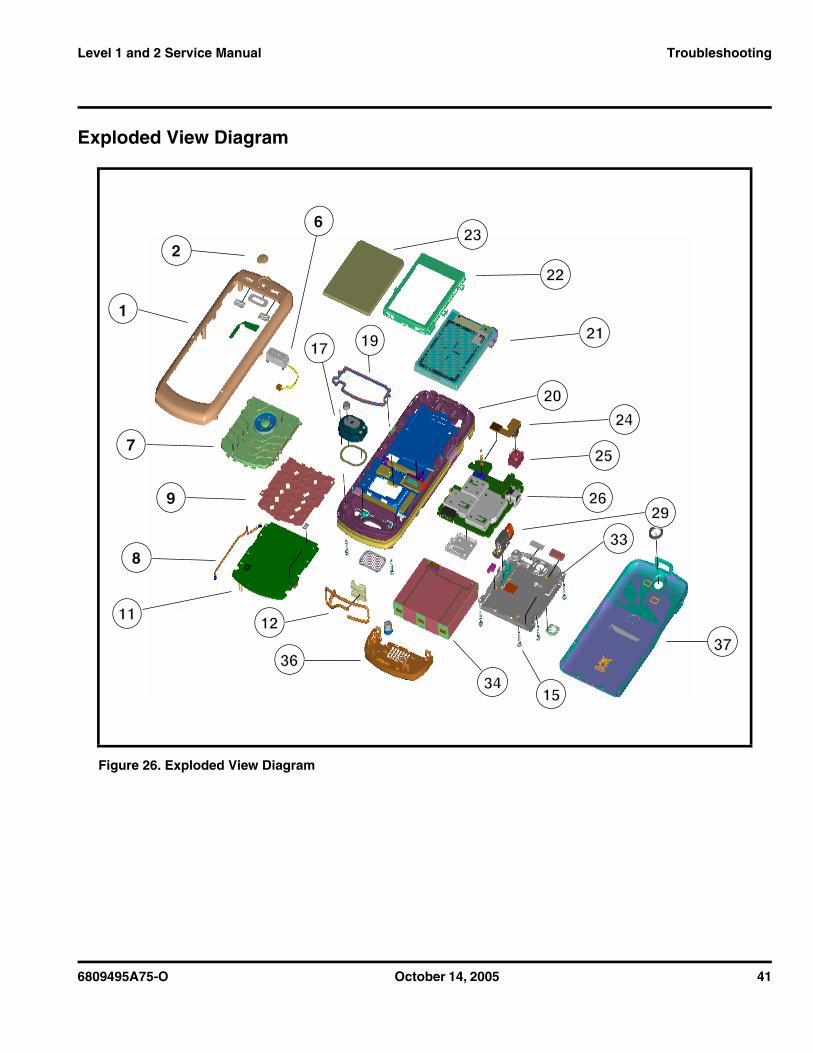
Exploded View Diagram
Figure 26. Exploded View Diagram
2222
34341515
3636
2121
2323
2020
2525
2424
26262929
3333
3737
1
6
2
7
1717 1919
9
8
1111 1212
42 October 14, 2005 6809495A75-O
Troubleshooting L6
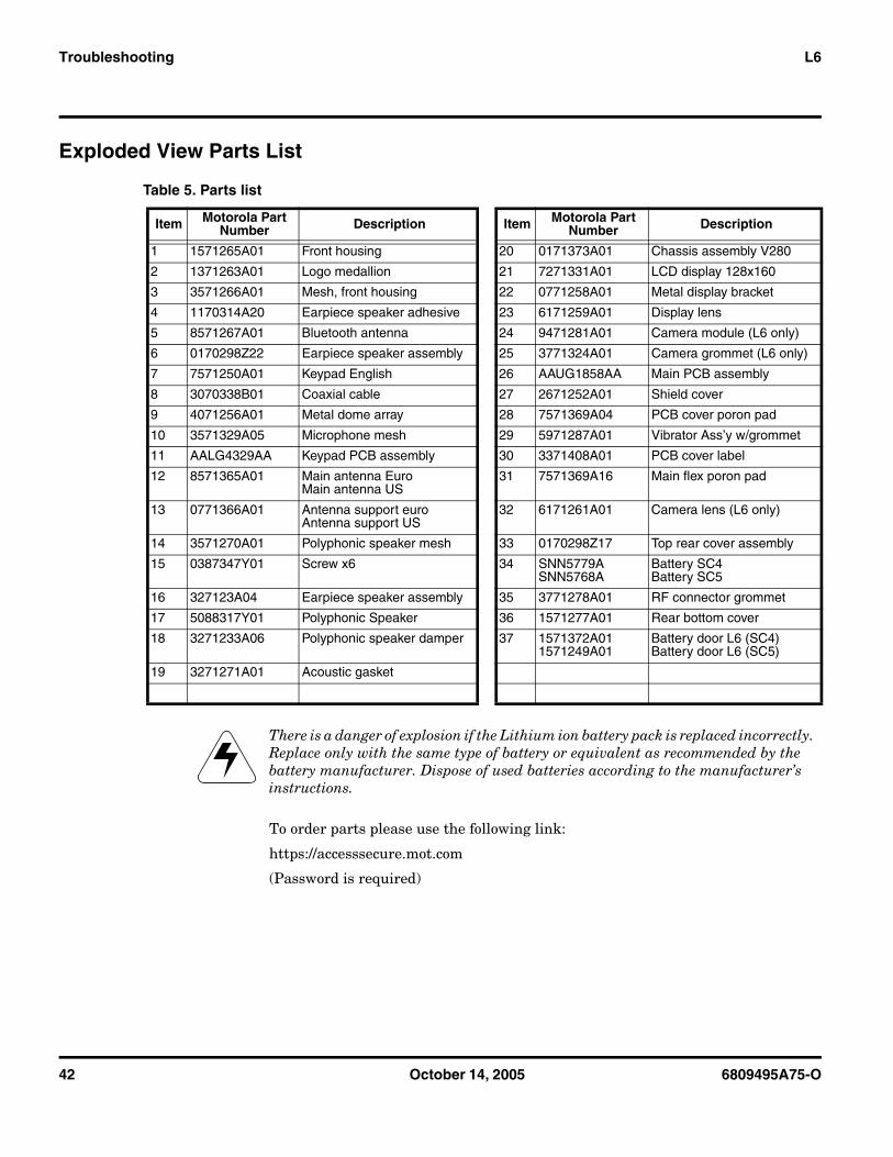
Exploded View Parts List
To order parts please use the following link:
https://accesssecure.mot.com
(Password is required)
Table 5. Parts list
Item Motorola Part Number Description Item Motorola Part
Number Description
1 1571265A01 Front housing 20 0171373A01 Chassis assembly V280
2 1371263A01 Logo medallion 21 7271331A01 LCD display 128x160
3 3571266A01 Mesh, front housing 22 0771258A01 Metal display bracket
4 1170314A20 Earpiece speaker adhesive 23 6171259A01 Display lens
5 8571267A01 Bluetooth antenna 24 9471281A01 Camera module (L6 only)
6 0170298Z22 Earpiece speaker assembly 25 3771324A01 Camera grommet (L6 only)
7 7571250A01 Keypad English 26 AAUG1858AA Main PCB assembly
8 3070338B01 Coaxial cable 27 2671252A01 Shield cover
9 4071256A01 Metal dome array 28 7571369A04 PCB cover poron pad
10 3571329A05 Microphone mesh 29 5971287A01 Vibrator Ass’y w/grommet
11 AALG4329AA Keypad PCB assembly 30 3371408A01 PCB cover label
12 8571365A01 Main antenna EuroMain antenna US
31 7571369A16 Main flex poron pad
13 0771366A01 Antenna support euroAntenna support US
32 6171261A01 Camera lens (L6 only)
14 3571270A01 Polyphonic speaker mesh 33 0170298Z17 Top rear cover assembly
15 0387347Y01 Screw x6 34 SNN5779ASNN5768A
Battery SC4Battery SC5
16 327123A04 Earpiece speaker assembly 35 3771278A01 RF connector grommet
17 5088317Y01 Polyphonic Speaker 36 1571277A01 Rear bottom cover
18 3271233A06 Polyphonic speaker damper 37 1571372A011571249A01
Battery door L6 (SC4)Battery door L6 (SC5)
19 3271271A01 Acoustic gasket
EThere is a danger of explosion if the Lithium ion battery pack is replaced incorrectly. Replace only with the same type of battery or equivalent as recommended by the battery manufacturer. Dispose of used batteries according to the manufacturer’s instructions.
6809495A75-O October 14, 2005 43
Level 1 and 2 Service Manual Troubleshooting
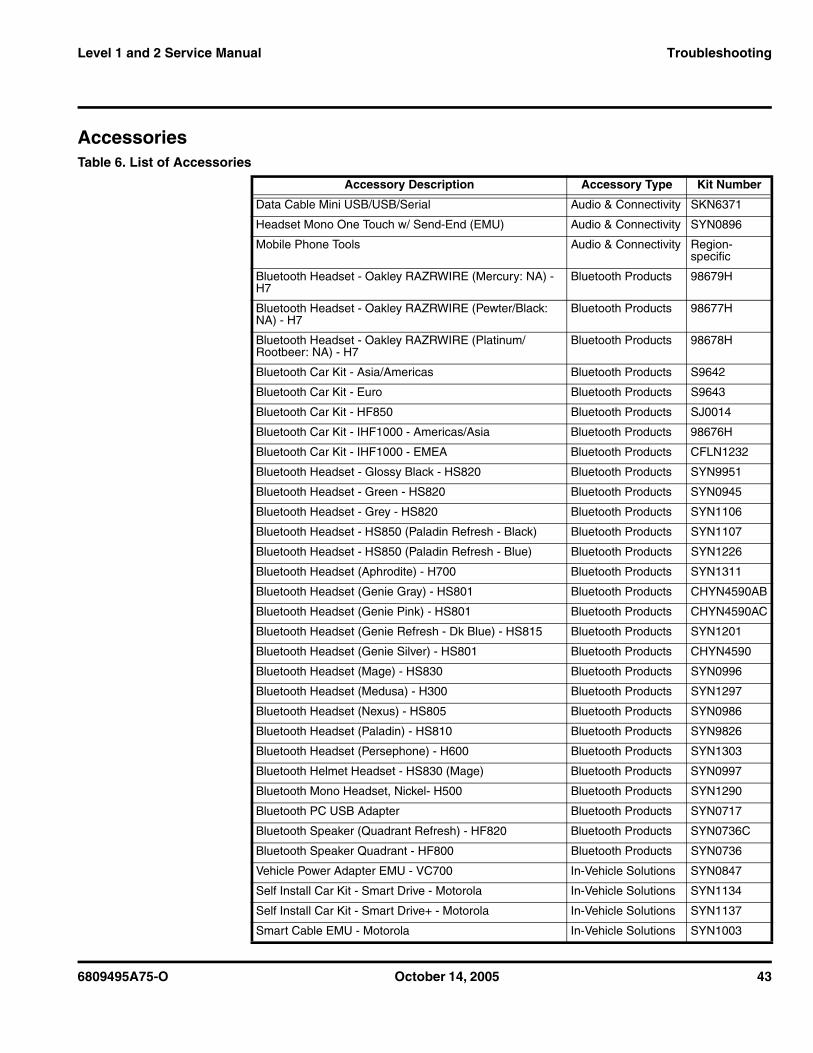
AccessoriesTable 6. List of Accessories
Accessory Description Accessory Type Kit Number
Data Cable Mini USB/USB/Serial Audio & Connectivity SKN6371
Headset Mono One Touch w/ Send-End (EMU) Audio & Connectivity SYN0896
Mobile Phone Tools Audio & Connectivity Region-specific
Bluetooth Headset - Oakley RAZRWIRE (Mercury: NA) - H7
Bluetooth Products 98679H
Bluetooth Headset - Oakley RAZRWIRE (Pewter/Black: NA) - H7
Bluetooth Products 98677H
Bluetooth Headset - Oakley RAZRWIRE (Platinum/Rootbeer: NA) - H7
Bluetooth Products 98678H
Bluetooth Car Kit - Asia/Americas Bluetooth Products S9642
Bluetooth Car Kit - Euro Bluetooth Products S9643
Bluetooth Car Kit - HF850 Bluetooth Products SJ0014
Bluetooth Car Kit - IHF1000 - Americas/Asia Bluetooth Products 98676H
Bluetooth Car Kit - IHF1000 - EMEA Bluetooth Products CFLN1232
Bluetooth Headset - Glossy Black - HS820 Bluetooth Products SYN9951
Bluetooth Headset - Green - HS820 Bluetooth Products SYN0945
Bluetooth Headset - Grey - HS820 Bluetooth Products SYN1106
Bluetooth Headset - HS850 (Paladin Refresh - Black) Bluetooth Products SYN1107
Bluetooth Headset - HS850 (Paladin Refresh - Blue) Bluetooth Products SYN1226
Bluetooth Headset (Aphrodite) - H700 Bluetooth Products SYN1311
Bluetooth Headset (Genie Gray) - HS801 Bluetooth Products CHYN4590AB
Bluetooth Headset (Genie Pink) - HS801 Bluetooth Products CHYN4590AC
Bluetooth Headset (Genie Refresh - Dk Blue) - HS815 Bluetooth Products SYN1201
Bluetooth Headset (Genie Silver) - HS801 Bluetooth Products CHYN4590
Bluetooth Headset (Mage) - HS830 Bluetooth Products SYN0996
Bluetooth Headset (Medusa) - H300 Bluetooth Products SYN1297
Bluetooth Headset (Nexus) - HS805 Bluetooth Products SYN0986
Bluetooth Headset (Paladin) - HS810 Bluetooth Products SYN9826
Bluetooth Headset (Persephone) - H600 Bluetooth Products SYN1303
Bluetooth Helmet Headset - HS830 (Mage) Bluetooth Products SYN0997
Bluetooth Mono Headset, Nickel- H500 Bluetooth Products SYN1290
Bluetooth PC USB Adapter Bluetooth Products SYN0717
Bluetooth Speaker (Quadrant Refresh) - HF820 Bluetooth Products SYN0736C
Bluetooth Speaker Quadrant - HF800 Bluetooth Products SYN0736
Vehicle Power Adapter EMU - VC700 In-Vehicle Solutions SYN0847
Self Install Car Kit - Smart Drive - Motorola In-Vehicle Solutions SYN1134
Self Install Car Kit - Smart Drive+ - Motorola In-Vehicle Solutions SYN1137
Smart Cable EMU - Motorola In-Vehicle Solutions SYN1003
44 October 14, 2005 6809495A75-O
Troubleshooting L6
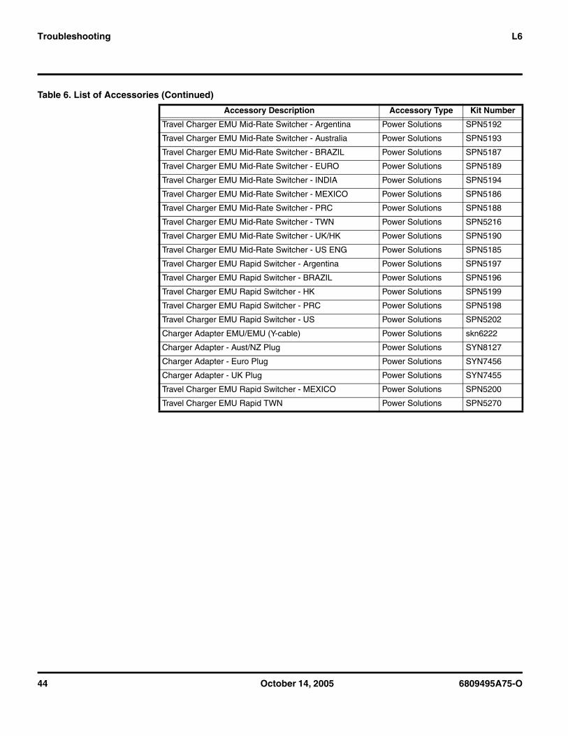
Travel Charger EMU Mid-Rate Switcher - Argentina Power Solutions SPN5192
Travel Charger EMU Mid-Rate Switcher - Australia Power Solutions SPN5193
Travel Charger EMU Mid-Rate Switcher - BRAZIL Power Solutions SPN5187
Travel Charger EMU Mid-Rate Switcher - EURO Power Solutions SPN5189
Travel Charger EMU Mid-Rate Switcher - INDIA Power Solutions SPN5194
Travel Charger EMU Mid-Rate Switcher - MEXICO Power Solutions SPN5186
Travel Charger EMU Mid-Rate Switcher - PRC Power Solutions SPN5188
Travel Charger EMU Mid-Rate Switcher - TWN Power Solutions SPN5216
Travel Charger EMU Mid-Rate Switcher - UK/HK Power Solutions SPN5190
Travel Charger EMU Mid-Rate Switcher - US ENG Power Solutions SPN5185
Travel Charger EMU Rapid Switcher - Argentina Power Solutions SPN5197
Travel Charger EMU Rapid Switcher - BRAZIL Power Solutions SPN5196
Travel Charger EMU Rapid Switcher - HK Power Solutions SPN5199
Travel Charger EMU Rapid Switcher - PRC Power Solutions SPN5198
Travel Charger EMU Rapid Switcher - US Power Solutions SPN5202
Charger Adapter EMU/EMU (Y-cable) Power Solutions skn6222
Charger Adapter - Aust/NZ Plug Power Solutions SYN8127
Charger Adapter - Euro Plug Power Solutions SYN7456
Charger Adapter - UK Plug Power Solutions SYN7455
Travel Charger EMU Rapid Switcher - MEXICO Power Solutions SPN5200
Travel Charger EMU Rapid TWN Power Solutions SPN5270
Table 6. List of Accessories (Continued)
Accessory Description Accessory Type Kit Number
6809495A75-O October 14, 2005 45
Level 1 and 2 Service Manual Troubleshooting
Related Publications
Programming: Software Upgrade and FlexingContact your local technical support engineer for information about equipment and procedures for flashing and flexing.
Motorola L6 User’s Guide (English) 68XXXXX106
46 October 14, 2005 6809495A75-O
Troubleshooting L6
6809495A75-O October 14, 2005 1
Level 1 and 2 Service Manual Index
Index
Aalert settings 14antenna, removing and replacing 20
Bbattery
charge indicator 14function 14
Battery cover, removing and replacing 17battery, removing and replacing 17, 18
Ccaller ID 10camera assembly, removing and replacing 27Canadian Interference-Causing Equipment regulations 4commands, manual test mode 37copyrights
computer software 5
Ddisassembly 17display module, removing and replacing 32
Eexploded view diagram 41exploded view parts list 42
FFCC rules 4features
caller ID 10Front Housing, removing and replacing 28
Iidentification
international mobile station equipment identity 35mechanical serial number 34product 4
identification, labels 34, 36IMEI 35Introduction 4
Kkeypad PC board, removing and replacing 30, 31
keypad, removing and replacing 31
LLCD 12liquid crystal display (LCD) 12
Mmanual test mode 37menu structure 14motor/vibrator, removing and replacing 23MSN 34
Nnames
product 4
Ooperation 12
alert settings 14battery 14controls, indicators, and I/O connectors 12icons 13LCD 12menu navigation 12menu structure 14
overview, product 10
Pparts
exploded view diagram 41exploded view parts list 42
Parts Replacement 7product
identification 4names 4
product overview 10features 10
publications, related 45
Rregulatory agency compliance 4related publications 45Removing
keypad 31removing
antenna 20battery 15, 17, 18
1 and 2Index6809495A75-OL6
2 October 14, 2005 6809495A75-O
Index L6
battery cover 17camera assembly 27display module 32front housing 28keypad PC board 30, 31motor/vibrator 23SIM 19Tranceiver PC Board 24Tranceiver PC Board Shield 22
replacingantenna 20battery 17, 18battery cover 17camera assembly 27display module 32front housing 28keypad 31keypad PC board 31keypad PC board shield 30motor/vibrator 23SIM 19Tranceiver PC Board 24Tranceiver PC Board Shield 22
Sserial number
mechanical 34service manual
about 5audience 5conventions 6scope 5
service policy 6customer support 6out of box failure 6product support 6
shut downupon battery removal 15
SIM, description 34SIM, removing and replacing 19specifications 8subscriber identity module (SIM) 34support
customer 6product 6
Ttest equipment 16tools, disassembly 16Tranceiver PC Board Shield, removing and replacing 22
Tranceiver PC Board, removing and replacing 24troubleshooting 37
manual test mode 37manual test mode commands 37troubleshooting chart 39
Wwarranty service 6

MOTOROLA, the Stylized M Logo, and all other trademarks indicated as such herein are trademarks of Motorola, Inc.® Reg. U.S. Pat. & Tm. Off.
© 2005 Motorola, Inc.All rights reserved.
Personal Communications Sector,789 International Parkway, Room S2C
Sunrise, FL 33325-6220.
@6809495A75@6809495A75-O
GSM SERVICE SUPPORT GROUP 2005.09.12
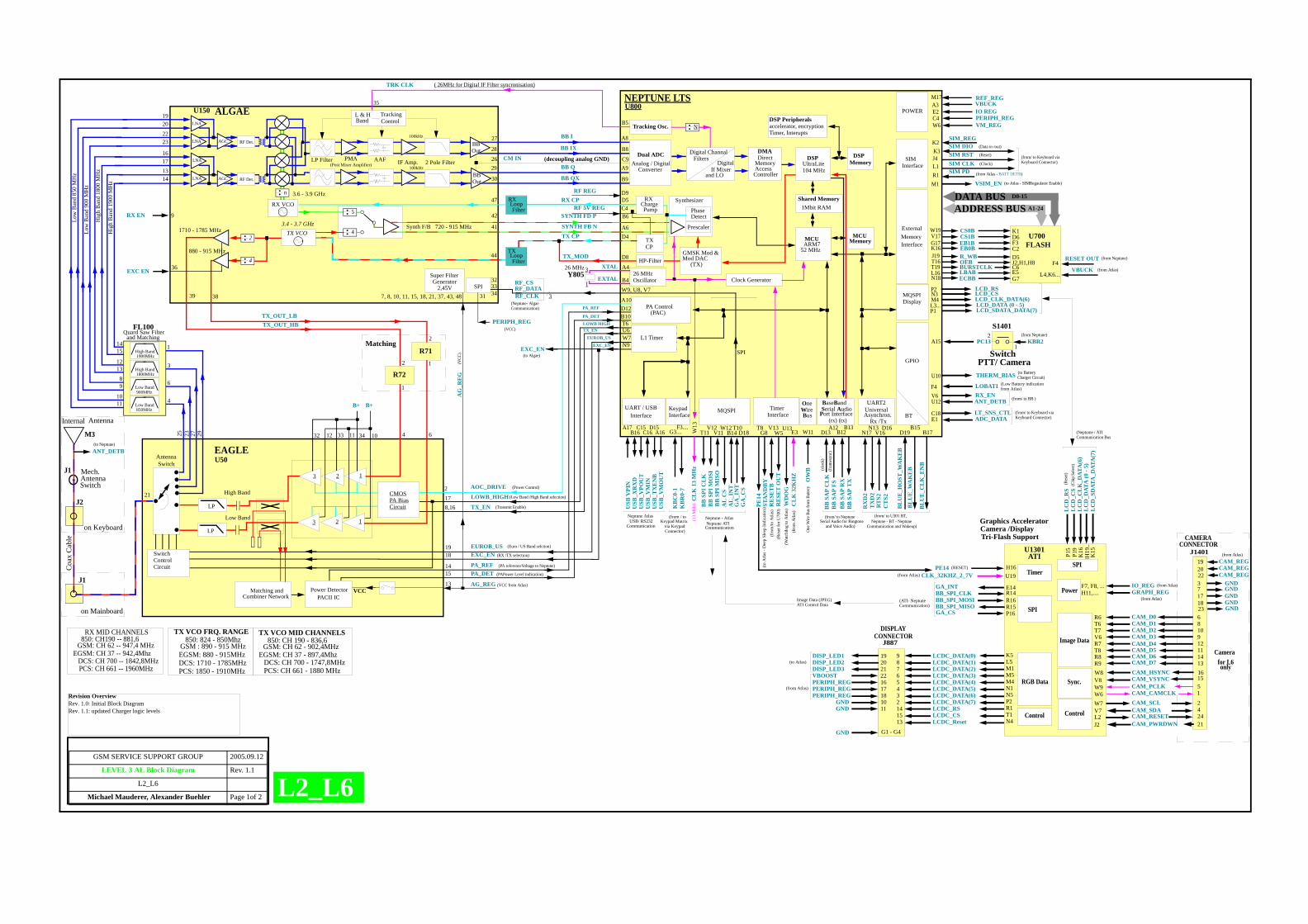
LEVEL 3 AL Block Diagram Rev. 1.1
L2_L6
Michael Mauderer, Alexander Buehler Page 1of 2
AOC_DRIVE
AntennaSwitch
FL100Quard Saw Filter
4
3
25
RX CP
TX CP
D547
Synth F/B
SYNTH FD P
SYNTH FB N
TX_OUT_HBTX_OUT_LB
3839
41
42
44
CM IN26 C9
BB I
BB IX
BB Q
BB QX
A8
B8
A9
B9
27
28
29
30
B6
LP Filter
TrackingControl
Tracking Osc.
AG_REG
RXCharge
TXCP
C4
D9
7, 8, 10, 11, 15, 18, 21, 37, 43, 48
PERIPH_REG
RF_CSRF_DATARF_CLK 3
W9, U8, V7
GMSK Mod &Mod DAC
(TX)
PA Control(PAC)
Y8053
1
A4
Power DetectorPACII IC
VCC
2
64
17 LOWB_HIGH
T6
TX_EN
U6
8,16
SwitchControlCircuit
W7N9
RF 5V REG
EXC_ENEUROB_US
PA_REFPA_DET
D12B10
PA_REF
PA_DET
LOWB HIGHTX_EN
EXC_EN
EUROB_US
Digital ChannalFilters
26 MHz
Timer
1918
1415
13Matching and
Combiner Network
LP
LP
Low Band
High Band
3
3
DMA
1Mbit RAM
PMA AAF
2
2 1
1
Pump
Super FilterGenerator
2,45V
5
4D4A6720 - 915 MHz1710 - 1785 MHz
880 - 915 MHz
Synthesizer
Prescaler
PhaseDetect
Dual ADC DSPDSPUltraLite104 MHz
DSP Peripheralsaccelerator, encryptionTimer, Interupts
Shared Memory
MCU
52 MHzARM7
MCU
26 MHzOscillatorB4
Memory
Memory SIMInterface
SIM DIOSIM RSTSIM CLK
J4L1
K3
SIM PDR1
MQSPIDisplay
GPIO
M1 VSIM_EN
External
Interface Memory
U13
(decoupling analog GND)
HP-FilterD8TXLoopFilter
Clock Generator
L1 Timer
NEPTUNE LTSALGAEU150 U800
XTAL
EXTAL
InterfaceUART / USB
Interface
TRK CLK
B5
35
( 26MHz for Digital IF Filter syncronisation)
EXC EN
EXC_EN
(Post Mixer Amplifier)
BBOut
BBOut
IF Amp. 2 Pole Filter
L & H Band
L2_L6
Low
Ban
d 85
0 M
Hz
EGSM: CH 37 -- 942,4MhzDCS: CH 700 -- 1842,8MHzPCS: CH 661 -- 1960MHz
RX MID CHANNELS
GSM: CH 62 -- 947,4 MHz850: CH190 -- 881,6
EGSM: 880 - 915MHzDCS: 1710 - 1785MHz
TX VCO FRQ. RANGE850: 824 - 850Mhz
PCS: 1850 - 1910MHz
EGSM: CH 37 - 897,4MhzDCS: CH 700 - 1747,8MHz
TX VCO MID CHANNELS
GSM: CH 62 - 902,4MHz
PCS: CH 661 - 1880 MHz
850: CH 190 - 836,6GSM : 890 - 915 MHz
DirectMemoryAccessController
Analog / DigitalConverter
SPI32333431
36
2
4
TX VCO3.4 - 3.7 GHz
100kHz
100kHz
N
and LO
Digital If Mixer
BaseBand
Port InterfaceSerial Audio
BB
SA
P T
XB
B S
AP
RX
BB
SA
P FS
BB
SA
P C
LK
B13B12
A12D13
(fram
esyn
c)
(clo
ck)
(tx)(rx)
TX_MOD
A10
CL
K 1
3 M
Hz
W13C15
C16D15
A16
KeypadInterface
BB
SPI
CL
KB
B S
PI M
OSI
BB
SPI
MIS
OA
L C
S
Neptune - Atlas
Communication
MQSPI
T11V12
V11W12
STA
ND
BY
G8
CL
K 3
2KH
Z
E3B14
AL
_IN
T
RE
SET
B
V13
(13
MH
z)
(Wat
chdo
g to
Atla
s)W
DO
G
(VCC from Atlas)
AG
_RE
G(V
CC)
V6 RX_EN
OW
B
W11
One
Wire
Bus
from
Bat
tery
U10
A15 PC13
RXLoopFilter
POWER
SPI
VBUCKIO REG
AGC RF Det.
AGC RF Det.
RX VCO
3.6 - 3.9 GHzn
LNA
LNA
LNA
LNA
23 27 29
Low Band850MHz
Low Band900MHz
High Band1800MHz
High Band1900MHz
21
6
1and Matching
Low
Ban
d 90
0 M
Hz
Hig
h B
and
1800
MH
z
1415
1213
89
1011
Hig
h B
and
1900
MH
z1920
2223
16171314
EAGLEU50
CMOSPA BiasCircuit
3332 10341112
B+ B+
(to Algae)
(VCC)
U700EB1BEB0B
OEBR_WB
CS1B
ADDRESS BUSDATA BUS
K16J19
G17
T16BURSTCLKLBABECBB
V17
T19L16N18
A1-24
D0-15
RESET OUT
F3C2
D6
E5
D5J2,H1,H8
G7
C6F4
(from Atlas - BATT DETB)
E2
USB
VPI
NU
SB_X
RX
DU
SB_V
POU
TU
SB_V
MIN
USB
_TX
EN
BU
SB_V
MO
UT
B16A17
RF REG
K2SIM_REG
A3M17
Neptune AtlasUSB/ RS232
Communication
(fro
m/to
Atla
s)R
ESE
T O
UT
W5
One
Bus Wire
RX EN 9
(from/ to NeptuneSerial Audio for Ringtone
and Voice Audio)
RX
D2
TX
D2
RT
S2C
TS2
UART2
N17N13
V16D16
UniversalAsynchron.
Rx /Tx
(from/ to U301 BT,Neptune - BT - Neptune
Communication and Wakeup)
BT
BL
UE
_WA
KE
B
BL
UE
_HO
ST_W
AK
EB
D19B15
KB
R0-
7K
BC
0-1
F3....G3....
P2 LCD_RS
M4 LCD_CLK_DATA(6) N3 LCD_CS
L3... LCD_DATA (0 - 5)
ADC_DATAE1
(from Neptune)
FLASH
VBUCKL4,K6...
BL
UE
_CL
K_E
NB
B17
PE14
Neptune ATI
(to Battery Charger Circuit)
GA
_IN
T
T10
GA
_CS
D18
ANT_DETBU12 (from/ to BB )
J887
192021221617181011
G1 - G4
98765432141513
DISP_LED1DISP_LED2DISP_LED3
LCDC_DATA(0)LCDC_DATA(1)LCDC_DATA(2)LCDC_DATA(3)LCDC_DATA(4)LCDC_DATA(5)LCDC_DATA(6)LCDC_DATA(7)LCDC_RSLCDC_CSLCDC_Reset
DISPLAYCONNECTOR
K5L5M1M5M4N1N5P2R1T1N4
LC
D_C
LK
_DAT
A(6
) L
CD
_CS
LC
D_D
ATA
(0 -
5)
LC
D_R
S
(Neptume / ATI Communication Bus
P1 LCD_SDATA_DATA(7)
LC
D_S
DAT
A_D
ATA
(7)
BH
19..
K15P15
P19
K16
BB_SPI_CLKBB_SPI_MOSIBB_SPI_MISOGA_CS
(ATI- Neptune Communication)
Camera /DisplayGraphics Accelerator
Tri-Flash Support
ATIU1301
R16R15P16
R14
J1401
GND
CONNECTOR
3
21
2
5
7
68109
16
17
19
12111413
18
1
15
424
2220
CAM_PWRDWN
CAM_SCL
CAM_PCLK
GND
CAM_D0CAM_D1CAM_D2CAM_D3
CAM_HSYNC
GND
CAM_REG
CAM_REG
CAM_RESET
CAM_VSYNC
CAM_CAMCLK
GND
CAM_D7CAM_D6CAM_D5CAM_D4
CAM_REG
J2
W9
R6T6T7V6
W8
L2
V8
W6
R9R8T8R7
H16
IO_REGGRAPH_REGH11,....
F7, F8, ...
U19CLK_32KHZ_2_7V
Image Data (JPEG)ATI Control Data
RGB Data
Image Data
Sync.
W7CAM_SDAV7ControlControl
SPI
Power
TimerSPI
C18 LT_SNS_CTL
Revision OverviewRev. 1.0: Initial Block DiagramRev. 1.1: updated Charger logic levels
R71
R72
2
12
1
Matching
Internal Antenna
M3
J2
Coa
x C
able
ANT_DETB(to Neptune)
J1
on Keyboard
J1
on Mainboard
Mech.AntennaSwitch
CS0BW19 K1
PERIPH_REGC4
REF_REG
VM_REGW6
THERM_BIAS
(from / to Keypad Matrix
via Keypad Connector)
23 GND
CAMERA
(from Atlas)
GA_INT E14
(to Atlas)
VBOOSTPERIPH_REGPERIPH_REGPERIPH_REG
(from Atlas)
GNDGND
GND
(RESET)
PE14
T8
PTT/ Camera
KBR2
Switch1
2
(from/ to Keyboard via Keyboard Connector)
(from/ to Keyboard via Keyboard Connector)
S1401
LOBATI (Low Battery indication F4 from Atlas)
(Power Control)
(Low Band /High Band selection)
(Transmit Enable)
(Euro / US Band selction)
(RX /TX selection)
(PA referenceVoltage to Neptune)
(PAPower Level indication)
(from Neptune)
(Res
et)
(Chi
p Se
lect
)
(from Atlas)
(from Atlas)
(from Atlas)
(from Atlas)
(Data in /out)
(Reset)
(Clock)
(to Atlas - SIMRegaulator Enable)
(Res
et fo
r U70
0)
(fro
m A
tlas)
(to A
tlas -
Dee
p Sl
eep
Indi
catio
n)
(Neptune- AlgaeCommunication)
Camera
only for L6
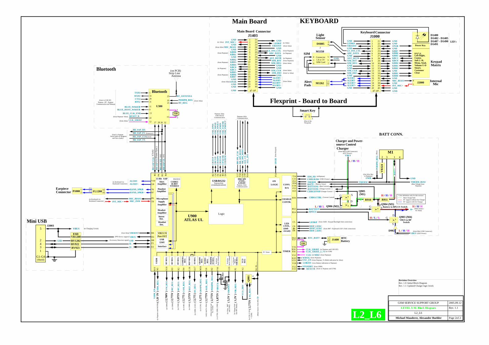
GSM SERVICE SUPPORT GROUP 2005.09.12
LEVEL 3 AL Block Diagram Rev. 1.1
L2_L6
Michael Mauderer, Alexander Buehler Page 2of 2L2_L6
Revision OverviewRev. 1.0: Initial Block DiagramRev. 1.1: Updated Charger logic levels
D1480
LED´s
(clock)
CLK 13 MHZV12CLK_32KHZ_2_7VP16TIMER
WDOGK10
CNTL.PRI SPI
LOGIC
Logic
G4,
J4...
....
Switc
her
BB
-SPI
_CL
KB
B_S
PI_M
OSI
BB
_SPI
_MIS
OA
UL
CS
U18
U16T1
8T1
7R5
Interface
USB
Y900
V17D12 RTC_BATT
V16
B+
HAND_SPKR-HAND_SPKR+
T6R7
T9P9
V10U8
ON
1BF1
4
B4
E3F3
U900ATLAS UL
ONLOGIC
OWB
THERM
GND
CHRGCTRLB16
VBUS
SG
DCHARGE
Charger
BATT CONN.
CNTL.LED
E12
BB
SA
P FS
BB
SA
P C
LK
BB
SA
P T
XB
B S
AP
RX
Neptune Atlas
CODEC16 BIT
STEREO
(tx) (rx)
Communication
ALERT-ALERT+
STANDBYF12
(to Neptune and U301 BT)A
UL
_IN
TN
14
RESETB(from U800)
Neptune AtlasCommunication
UID H8
Q904 (M3)G S B+ B12 BATTFET
Battery to BPLUS
USB
_VPI
NU
SB_X
RX
DU
SB_V
POU
TU
SB_V
MIN
USB
_TX
EN
BU
SB_V
MO
UT
USB/RS232(communication)
B2 C4
F4 B1 B3
E4
MIC_INMMIC_BIAS1
Det.Stereo
Boo
st 3
00m
AG
16
Switc
her
Buc
k 35
0mA
F16
( 1,8
75V
) V
BU
CK
H2
( 2,7
75V
) PE
RIP
H_
RE
G
U6
( 2,7
75V
) A
UD
_ R
EG
M18
( 1,2
75 )
GR
APH
_RE
G
K17
H4
H3
( 2,7
75V
) R
F_R
EG
L16
( 1,5
75V
) R
EF_
RE
G
N5
( 1,8
/ 3V
) SI
M_R
EG
VSI
MV
SIM
_EN
K11
VBUS
CONTR.
D6
AD
(One Wire Busto Neptune)
BPFET
VBUS to BPSwitch
(Main Sourcefor Atlas)
(from Mini USB Connector)
Main Charge PathB+ support without Ext ChargerB+ support with Ext Charger
Color definition only for this section !
D902
BB_SAP_TX
BB_SAP_RXBB_SAP_FSBB_SAP_CLK
(framesync)
Bluetooth
U300
32302827
BLUE_WAKEB 11BLUE_HOST_WAKEB 9
TXD2 5
CTS2RTS2 31
RXD2 3329
RESET_B22(from Neptune/ Atlas)
(from/ to NeptuneSerial Audio for Ringtone
and Voice Audio)
PERIPH_REG10BT_REG21
BT_ANTENNA25
Strip Line Antenna
(on PCB)
Y300
15
16
12
VIB
_RE
G(to
Vib
rato
r Pad
s
(from Neptune)
NeptuneAtlas
Neptune AtlasUSB/ RS232
Communication
C6B6
CONV.D/A
CLK_32KHZ(from Atlas)
1M1262 12
(from Atlas)( 1
,3V
)
(from/ to U301 BT,Neptune - BT - Neptune
Communication and Wakeup)
InternalMic
AlertPads
EXC_ENU15 (from Neptune, Tx Mode indication for Atlas)
( 2,7
75 )
IO_R
EG
( 2,7
75 )
CA
M_R
EG
( 5,5
V )
VB
OO
ST
43
VBUS5
2
1
(to Charging Circuit)
G1-G4(Shield)
UID
CLK_32KHZR16
D-D+
VBUS 5VPass FET
VBOOST
VBUS D2(PPD device support)
1
3
(to J1300)
C91
3
C92
9
to V
ibra
tor
VIB
RE
GP2
B+ Sense
Mot
or
near
RTC
Bat
tery
RE
F R
EG
RF
RE
G
PER
IPH
IO
RE
G
AU
DIO
RE
G
IO R
EG
GR
APH
RE
G
CA
ME
RA
RE
G
K2
( 1,8
75V
) B
T_R
EG
BT
RE
G
4
Microphone
R3
P4 R4
(tx)
(rx)
13 Bit
Handset
Amplifier
Q90
1
VC
OR
EG
VC
O_D
RV
(Mai
n So
urce
- fro
m M
3)
( 2,7
75V
) A
G_R
EG
V2
S
GD Q903 (M4)
Q905
GS
M132 41
R910 R911
DSwitch
B14
(Current Control)
Q906 (M2)
DISP_LED2DISP_LED3
DISP_LED1
(onl
y us
ed in
Atla
s)
LEDKPC5
(to U
800)
(Atla
s int
erna
l and
AL
circ
uit)
( to
U70
0, U
800,
U90
0)
(to J1
401)
(to N
eptu
ne a
md
M13
50))
(to U
800)
(to U
300)
(to U
800,
U13
01)
(to A
tlas ,
J887
(to U
50, U
150
Bluetooth
Mini USB
Charger and Power-source Control
(from J887 - Keyboard LED´s Sink connection)
(from/ to Neptune and U700)
(from Atlas)
(from Neptune)
THERM_BIAS(Bias Voltage from
Neptune)
(Accessory Detection signal)
(EXT Power)
(EXT Power)
VR
324
Det.Headset
BLUE_CLK_ENB 13
INT_MIC+
3
4
1
+ U
200)
ESD
RV922
VR1200RV1202
RV923
SAP
SupplyAmplifier
Alert
Amplifier
HeadsetAmplifier
EMU
J2003
UR
XV
PU
RC
VD
UD
ATPV
UR
XV
MU
TX
EN
BU
SE0V
M
J2000
A3A1FL1200C3
C1
21P1000
EarpieceConnector
(sink-circuit)
D1482 - D1485D1487 - D1490D1491
J140012
RTCBattery
BAT
T+PE
RIP
H_R
EG
(Bia
s)(from Mini USB Connector)
THERMP13
BATTISNSBATT+D14
U14
C15
(Battery Sense)
(VBUS Sense)SIM_PDT14CHRGRAW
(Batt Current)
CHRGISNSPE15 (Charger Current + )
(toNeptune)
BATTISNSF13 (Charge Current - )
(M1)
and
J140
3)
(to U
1301
)
K16
( 2,7
00V
) V
M_R
EG
RF
RE
G(to
U80
0)
1 21GND GNDGNDON1BGND
KBR6KBR5KBC1KBC0KBR4
g1- g4 GND
KBR3KBR2GNDKBR1KBR0GNDMIC_BIAS1GNDINT_MIC+GND
KBR7
(to Keyboard via
0-9,*,#,Left-Right,Center,Soft L+R,Menu, Send,Volume U-DSmart, CustomerClear
Power Key22232425262728293031323334353637383940
234567891011121314151617181920
LEDKPVBOOSTGNDLT_SNS_CTLADC_DATAGNDANT_DETBSIM_RSTSIM_REGGNDGNDSIM_CLKSIM_DIOGNDALERT-ALERT-ALERT+ALERT+GND
(fro
m K
eypa
d)
16
4
23
GNDConnector
M1350
1.8 or 3VSIM Card
5
Keyboard Connector)
(to Keyboard viaKeyboard Connector)
KeypadMatrix
DS8051
26
LightSensor
SIM
KEYBOARD
GND
GNDON1BGND
KBR6KBR5KBC1KBC0KBR4KBR3KBR2GND
KBR1KBR0GND
MIC_BIAS1GND
INT_MIC+GND
KBR7
LEDKPVBOOST
GNDLT_SNS_CTL
ADC_DATAGND
ANT_DETBSIM_RSTSIM_REG
GNDGND
SIM_CLKSIM_DIO
GNDALERT-ALERT-ALERT+ALERT+
GND
GND1 21
g1- g4
22232425262728293031323334353637383940
23456789
1011121314151617181920GND
J1403 J1000Keyboard Connector
Main Board
Flexprint - Board to Board
1
2Smart Key
(Part of the Flexprint)
(to Atlas)
(from Atlas)
(from Neptune)
(from Neptune)
(from Neptune)
(to Neptune)
(from Atlas)
(from Neptune)
(from Atlas)
(to Neptune)
(to Neptune)(from Neptune)(from Atlas)
(from Atlas)(from/ to Atlas)
(from Atlas)
Main Board Connector
(to Atlas)
(from J1403 - Keypad Backlight Sink connection)
LOBATIV18 (Low Battery indication to Neptune)
(Clo
ck)
(Fra
me S
ync.)
L / H / H
H / L / L
H / H / H
H / H/ H
L / H / H
L / H/ L

������
������������������������������������
������������������������������
����
����
������
������������������������������
�������������������������
����
������������������������������
������������������������������
����
������
�������������������������
�������������������������
����
������
����
����
����������
������������������������������
������������������������������
����
����������
�������������������������
������������������������� ��
��
������������������������������
�������������������������
����
����
������������������������������
������������������������������������
������
������
�������������������������
������������������������������
���������
��������������������������������
��������
������������������������������
�������������������������
������
���������
���������
������������
������
������������
����
������
��������������������
����
�������������������������
������
���������
���������
������������
������
������������
����
������
��������������������
����
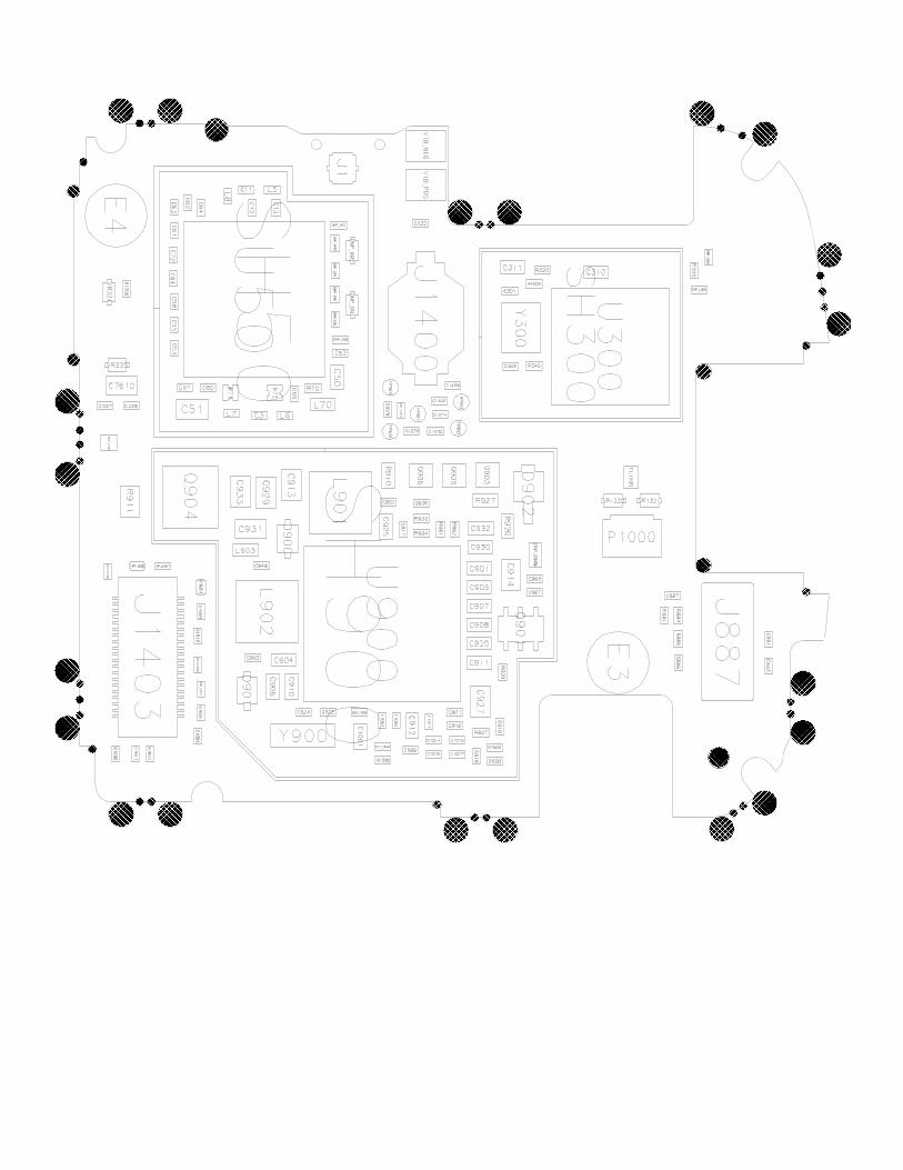
������
������������������������������������
������������������������������
����
����
������
������������������������������
�������������������������
����
������������������������������
������������������������������
����
������
�������������������������
�������������������������
����
������
����
����
����������
������������������������������
������������������������������
����
����������
�������������������������
������������������������� ��
��
������������������������������
�������������������������
����
����
������������������������������
������������������������������������
������
������
�������������������������
������������������������������
���������
��������������������������������
��������
������������������������������
�������������������������
������
���������
���������
������������
������
������������
����
������
��������������������
����
�������������������������
������
���������
���������
������������
������
������������
����
������
��������������������
����