Embed Size (px)
Citation preview

MOTORCYCLE LIFT RAMP99900
SET uP And OPERATIng InSTRuCTIOnS
distributed exclusively by Harbor Freight Tools®.
3491 Mission Oaks Blvd., Camarillo, CA 93011
Visit our website at: http://www.harborfreight.com
Read this material before using this product. Failure to do so can result in serious injury. SAvE THIS MAnuAL.
Copyright© 2008 by Harbor Freight Tools®. All rights reserved. No portion of this manual or any artwork contained herein may be reproduced in any shape or form without the express written consent of Harbor Freight Tools. Diagrams within this manual may not be drawn proportionally. Due to continuing improvements, actual product may differ slightly from the product described herein. Tools required for assembly and service may not be included.
For technical questions or replacement parts, please call 1-800-444-3353.
Motorcycle Lift Ramp partially hidden in truck bed.

SAvE THIS MAnuALKeep this manual for the safety warn-
ings and precautions, assembly, operating, inspection, maintenance and cleaning pro-cedures. Write the product’s serial number in the back of the manual (or month and year of purchase if product has no num-ber). Keep this manual and the receipt in a safe and dry place for future reference.
IMPORTAnT SAFETY InFORMATIOn
In this manual, on the labeling, and all other information provid-ed with this product:
This is the safety alert symbol. It is used to alert you to potential personal injury hazards. Obey all safety messages that follow this symbol to avoid possible injury or death.
dAngER indicates a hazardous
situation which, if not avoided, will result in death or serious injury.
WARnIng indicates a
hazardous situation which, if not avoided, could result in death or serious injury.
CAuTIOn, used with the safety
alert symbol, indicates a hazardous situation which, if not avoided, could result in minor or moderate injury.
nOTICE is used to address practices
not related to personal injury.
CAuTIOn, without the safety alert
symbol, is used to address practices not related to personal injury.
general Safety Warnings WARnIng Read all safety warnings and instructions. Failure to follow the warnings and instructions may result in serious injury. Save all warnings and instructions for future reference.
Work area safety1. Keep work area clean and well lit. a. Cluttered or dark areas invite acci-dents.Keep children and bystanders b. away while operating the Motor-cycle Lift Ramp. Distractions can cause you to lose control.
Personal safety2. Stay alert, watch what you are a. doing and use common sense when operating the Motorcycle Lift Ramp. do not use the Lift Ramp while you are tired or under the influence of drugs, alcohol or medication. A moment of inattention while operating the Lift Ramp may result in serious personal injury.use personal protective equip-b. ment. Always wear AnSI-approved safety goggles and heavy duty work gloves. Safety equipment
SKU 99900 For technical questions, please call 1-800-444-3353. Page 2

such as non-skid safety shoes will a. reduce personal injuries.do not overreach. Keep proper b. footing and balance at all times. This enables better control of the Motorcycle Lift Ramp in unexpected situations.dress properly. do not wear loose c. clothing or jewelry. Keep your hair, clothing and gloves away from moving parts. Loose clothes, jewelry or long hair can be caught in moving parts.Only use safety equipment that d. has been approved by an appropri-ate standards agency. Unapproved safety equipment may not provide adequate protection. Eye protection must be ANSI-approved for specific hazards in the work area.
Tool use and care3. do not force the Motorcycle Lift a. Ramp. use the correct equipment for your application. The correct equipment will do the job better and safer at the rate for which it was de-signed.Release any load from the Motor-b. cycle Lift Ramp before making any adjustments, changing acces-sories, or storing the unit. Such preventive safety measures reduce the risk of accidents.Store idle equipment out of the c. reach of children and do not allow persons unfamiliar with the Motor-cycle Lift Ramp or these instruc-tions to operate the unit. Hydraulic tools are dangerous in the hands of untrained users.Maintain the Motorcycle Lift Ramp. d. Check for misalignment or binding
of moving parts, breakage of parts and any other condition that may affect the unit’s operation. If dam-aged, have the Lift Ramp repaired before use. Many accidents are caused by poorly maintained equip-ment.use the Motorcycle Lift Ramp and e. its accessories in accordance with these instructions, taking into ac-count the working conditions and the work to be performed. Use of the Lift Ramp for operations different from those intended could result in a hazardous situation.
Service4. Have your Motorcycle Lift Ramp a. serviced by a qualified repair per-son using only identical replace-ment parts. This will ensure that the safety of the Lift Ramp is maintained.
Specific Safety WarningsMaintain labels and nameplates on 1. the Motorcycle Lift Ramp. These carry important safety information. If unreadable or missing, contact Har-bor Freight Tools for a replacement.
Do not exceed the 2. 1000 pound maximum weight capacity of the Motorcycle Lift Ramp. Doing so may cause damage to the unit and/or seri-ous personal injury. Beware of dy-namic loading. Dropping or bouncing a load may briefly create an excess load, causing product failure.
Tie down the motorcycle to the truck 3. bed using heavy duty straps (not in-cluded) with a rated working load limit of at least 1000 pounds.
SKU 99900 For technical questions, please call 1-800-444-3353. Page 3
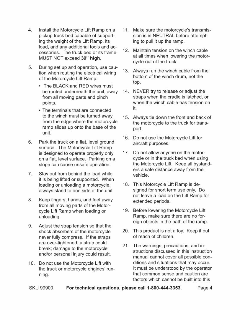
Install the Motorcycle Lift Ramp on a 4. pickup truck bed capable of support-ing the weight of the Lift Ramp, its load, and any additional tools and ac-cessories. The truck bed or its frame MUST NOT exceed 39” high.
During set up and operation, use cau-5. tion when routing the electrical wiring of the Motorcycle Lift Ramp:
The BLACK and RED wires must • be routed underneath the unit, away from all moving parts and pinch points.The terminals that are connected • to the winch must be turned away from the edge where the motorcycle ramp slides up onto the base of the unit.
Park the truck on a flat, level ground 6. surface. The Motorcycle Lift Ramp is designed to operate properly only on a flat, level surface. Parking on a slope can cause unsafe operation.
Stay out from behind the load while 7. it is being lifted or supported. When loading or unloading a motorcycle, always stand to one side of the unit.
Keep fingers, hands, and feet away 8. from all moving parts of the Motor-cycle Lift Ramp when loading or unloading.
Adjust the strap tension so that the 9. shock absorbers of the motorcycle never fully compress. If the straps are over-tightened, a strap could break; damage to the motorcycle and/or personal injury could result.
Do not use the Motorcycle Lift with 10. the truck or motorcycle engines’ run-ning.
Make sure the motorcycle’s transmis-11. sion is in NEUTRAL before attempt-ing to pull it up the ramp.
Maintain tension on the winch cable 12. at all times when lowering the motor-cycle out of the truck.
Always run the winch cable from the 13. bottom of the winch drum, not the top.
NEVER try to release or adjust the 14. straps when the cradle is latched, or when the winch cable has tension on it.
Always tie down the front and back of 15. the motorcycle to the truck for trans-port.
Do not use the Motorcycle Lift for 16. aircraft purposes.
Do not allow anyone on the motor-17. cycle or in the truck bed when using the Motorcycle Lift. Keep all bystand-ers a safe distance away from the vehicle.
This Motorcycle Lift Ramp is de-18. signed for short term use only. Do not leave a load on the Lift Ramp for extended periods.
Before lowering the Motorcycle Lift 19. Ramp, make sure there are no for-eign objects in the path of the ramp.
This product is not a toy. Keep it out 20. of reach of children.
The warnings, precautions, and in-21. structions discussed in this instruction manual cannot cover all possible con-ditions and situations that may occur. It must be understood by the operator that common sense and caution are factors which cannot be built into this
SKU 99900 For technical questions, please call 1-800-444-3353. Page 4

product, but must be supplied by the operator.
SPECIFICATIOnSMaximum Load Capacity 1000 Pounds
Maximum Lifting Height 39”
Winch Voltage 12 VDC
Winch Cable Type and SizeAircraft Cable0.241” Diameter(with Plastic Coating)
Remote Control Cord Length 14’-3”
Battery Cable Length 19’-7”
Maximum Wheel With 5-3/4”
Accessories Tie-Down Straps (Qty.2)
unPACKIngWhen unpacking, check to make sure
that the item is intact and undamaged. If any parts are missing or broken, please call Harbor Freight Tools at the number shown on the cover of this manual as soon as possible.
InSTALLATIOn InSTRuCTIOnS
Read the EnTIRE IMPORTAnT SAFETY InFORMATIOn section at the beginning of this manual including all text under subheadings therein before set up or use of this product.
TO PREvEnT SERIOuS
InjuRY FROM ACCIdEnTAL OPERATIOn: Release any load from the Motorcycle Lift before assembling or making any adjustments to the unit. Also
disconnect connectors from Battery negative terminals.
note: For additional information regarding the parts listed in the following pages, refer to the Assembly Diagram near the end of this manual.
To install the unit on a truck bed will 1. require additional manpower and a proper lifting device (forklift, crane, etc.). (See Figure A.)
In these instructions, “front” means 2. the end of the Lift Ramp closest to the Winch (2) and truck cab. “Rear” means the other end of the unit clos-est to the truck tailgate.
FIguRE A
FROnT
REAR
(unIT MOunTEdOn TRuCK
SHORT BEd)
3. Position the Motorcycle Lift Ramp in the truck bed. Make sure it is cen-tered in the bed, midway between the wheel wells.
Position the unit front-to-back so that 4. the Large Slide Base (21) extends to the ground without contacting the end of the truck bed or tailgate.
SKU 99900 For technical questions, please call 1-800-444-3353. Page 5

Long Bed:• Position the rear end of the Large Slide Base (21) inside the bed and just touching the closed tailgate. For very high trucks, it may be necessary to leave the tail-gate off.Short Bed (tailgate left on):• Posi-tion the rear end of the Large Slide Base (21) inside the tailgate, 1/2” to 1-1/2” from the end of the tailgate.Short Bed (tailgate off): • Posi-tion the front end of the Large Slide Base (21) immediately next to (with-in 1/2”) the front of the truck bed.Extreme Short Bed (tailgate on or • off): Position the front end of the Large Slide Base (21) immediately next to (within 1/2”) the front of the truck bed.Note: Attaching a red flag may be • required; contact your local Depart-ment of Motor Vehicles for regula-tions.
Remove the Winch’s Nylon Guide 5. Wheel (9) located on the Front Mounting Channel. There is a mount-ing hole under the Wheel. (See Figure B.)
There is also one mounting hole in 6. the Middle and Rear Mounting Chan-nel. (See Figures C and d.)
FIguRE C
MIddLEMOunTIng CHAnnEL
MOunTIngHOLE
FIguRE d
REARMOunTIngCHAnnEL MOunTIng
HOLE
Use the one mounting hole and two 7. mounting slots in the Front Mounting Channel as templates to mark and drill three 17/32” diameter holes in the truck bed. (See Figure B.)
Use the one mounting hole in either 8. the Middle Mounting Channel or Rear Mounting Channel as a template to mark and drill one 17/32” diameter hole in the truck bed. (See Figures C and d.)
SKU 99900 For technical questions, please call 1-800-444-3353. Page 6
FIguRE BTEMPORARILY
REMOvEnYLOn guIdE WHEEL (9)
TO EXPOSEHIddEn
MOunTIng HOLE
MOunTIngSLOT
MOunTIngSLOT
FROnTMOunTIngCHAnnEL

Make sure to position the mounting 9. holes so the Rivet Nuts (57) used will sit on a flat surface and not on a formed face of the bed. If neces-sary, slightly move the Motorcycle Lift Ramp sideways to ensure the unit’s mounting holes will be over a flat surface.
CAuTIOn!10. To ensure safety, the four mounting holes drilled in the truck bed MUST be 17/32” diameter.
Move the Base Frame (1) to one side 11. to clear room to install the four Rivet Nuts (57). (See Figure E.)
IMPORTANT: The Rivet Nuts (57) 12. must be installed directly on the sheet metal truck bed with no plastic or bed liner material between the Nut and the metal. If necessary, cut or scrape away the material completely in the immediate area where the Nut will be inserted. (See Figure E.)
Insert a Rivet Nut (57) in each of the 13. four truck bed mounting holes, mak-ing sure the Nut is fully inserted and flush with the top of the surface of the truck bed. (See Figure E.)
Use the provided Rivet Nut installa-14. tion tool according to its included in-structions. Tighten as instructed until each Rivet Nut (57) is tightly clamped against the sheet metal truck bed. (See Figure E.)
FIguRE E
RIvET nuT(57)
Move the Base Frame (1) to align the 15. four mounting holes in the Frame with the four inserted Rivet Nuts (57) in the truck bed. Secure the Base Frame to the truck bed using four Bolts (52), four Hex Sleeves (56), and four Flat Washers (53). (See Figure F.)
HEXSLEEvE
(56)
BOLT(52)
FLATWASHER
(53)
FIguRE F
Place the Slide Base (21) on the Base 16. Frame (1) with the rear of the Slide Base on the ground and its front lean-ing on the end of the Fixed Wheels (18) of the Base Frame. (See Assy. diagram.)
Install the Long Guide Rod (20) 17. through the Guide Pipe Support (15). Slide the Rod down through the Sup-port, then through the Hinged Guide, then into the Guide Block (15) under the Wheel Pan. (See Figure g.)
SKU 99900 For technical questions, please call 1-800-444-3353. Page 7

Secure the Long Guide Rod (20) to 18. the Guide Block (15) using one Bolt (16) and one Lock Nut (7). (See Figure g.)
FIguRE g
LOngguIdEROd(20)
guIdEBLOCK
(15)
BOLT (16)LOCK nuT (7)
Remove the Rear Slide Wheels (27) 19. from the Slide Base (21). (See Assy. diagram.)
Slide the Wheel Bracket Assembly 20. (39) into the Slide Base (21) tracks. (See Assy. diagram.)
Re-install the Rear Slide Wheels (27) 21. into the Slide Base (21). (See Assy. diagram.)
Re-install the Winch’s Nylon Guide 22. Wheel (9) located on the Front Mounting Channel. (See Figure B.)
Attach the Steel Cable (15A) to the 23. Wheel Bracket Assembly (39) using one Bolt (37), two Large Washers (38), and one Lock Nut (7). Make sure to route the Steel Cable over the Nylon Guide Wheel (9) near the Winch, and under the Slide Wheel
(44) near the Lock (40). (See Assy. diagram.)
Electrical Installation:
Mount the Winch Solenoid Box (25A) 1. to the left side plate of the Base Frame (1). (See Assy. diagram.)
To do so:Insert two Screws (14) • outwards through the two mounting holes in the Base Frame (1). Insert one Cable Boot (13) on each Screw. In-sert one Lock Washer (12) on each Screw. Then tighten the Screws into the threaded mounting holes in the Winch Solenoid Box (25A). (See Assy. diagram.) Make sure to orient the Winch Sole-• noid Box (25A) so that the Connec-tor for the Winch Remote Control (27A) faces towards the rear of the truck. You may need to relocate one of the mounting studs in the Solenoid Box Assembly. (See Assy. diagram.)
A Quick-Connect Plug is attached to 2. the Winch Solenoid Box. Connect this Plug to the other Quick-Connect Plug (26A) provided and its long wires. The long wires are attached to the truck’s battery terminals after completion of unit assembly. (See Assy. diagram.)
Route the long wires (26A) from the 3. Winch Solenoid Box (25A) to the truck’s battery terminals. Refer to your truck manufacturer’s recommen-dations for routing the Cables. (See Assy. diagram.)
Cut the long wires from the Winch 4. Solenoid Box (26A) to length and at-
SKU 99900 For technical questions, please call 1-800-444-3353. Page 8

tach them to the truck’s battery termi-nals, making sure to connect to the correct polarity. (RED wire to Positive +, BLACK wire to Negative --) (See Assy. diagram.)
Insert the Winch Remote Control 5. (27A) into the Connector on the Sole-noid Box Assembly (25A). (See Assy. diagram.)
Check to make sure the Winch winds 6. up the Steel Cable (15) when you press the RED Button on the Remote Control (27A). (See Assy. diagram.)
Check to make sure the Winch 7. unwinds the Steel Cable (15A) when you press the BLACK Button on the Remote Control (27A). (See Assy. diagram.)
OPERATIng InSTRuCTIOnS Read the EnTIRE IMPORTAnT
SAFETY InFORMATIOn section at the beginning of this manual including all text under subheadings therein before set up or use of this product.
Loading Instructions:
Remove the Travel Lock Pin (50). 1. (See Figure H.)
Check the Winch Remote Control 2. (27A) by briefly pressing the BLACK Button and then the RED Button. The RED Button causes the Winch to reel in. The BLACK Button causes the Winch to reel out. (See Assy. diagram.)
While unreeling the Winch with the 3. BLACK Button, pull the Large Slide Base (21) from the truck bed. The Large Slide Base will hit an internal stop when it is fully extended. (See Assy. diagram.)
Install a Small Lock Pin (51) prior to 4. loading the Slide Base (21). (See Figure I.)
FIguRE I
SMALLLOCK PIn
(51)
Remove the Small Lock Pin (51) to 5. allow the Wheel Bracket Assembly (39) to travel down the Large Slide Base (21). (See Figure j, next page.)
SKU 99900 For technical questions, please call 1-800-444-3353. Page 9
FIguRE H
LARgE LOCK PIn(50)

FIguRE j
SMALLLOCK
PIn(51)
Slide and position the Wheel Bracket 6. Assembly (39) at the bottom end nearest the ground. (See Figure K.)
FIguRE KWHEELBRACKET
ASSEMBLY(39)
Install the Small Lock Pin (51) so the 7. Wheel Bracket Assembly (39) cannot move up the Slide Base (21). The Wheel Bracket Assembly must be completely down and at the end of the Large Slide Base to install the Small Lock Pin. (See Figure L.)
FIguRE L
SMALLLOCK
PIn(51)
Unlatch the Wheel Bracket Assembly 8. Lock (40) so the Wheel Bracket can tilt up. If necessary, pull the Winch in, and tighten the Steel Cable (15A) enough for the Lock to release. After the Lock releases, make sure there is enough slack in the Steel Cable for the Wheel Bracket to tilt fully up. (See Figure M.)
FIguRE M
LOCK(40)
Push the motorcycle up to the Wheel 9. Bracket Assembly (39) and push the front wheel into the Wheel
SKU 99900 For technical questions, please call 1-800-444-3353. Page 10

Bracket. The Wheel Bracket will then tilt up againts the wheel.
Lower the kickstand, and lean the 10. motorcycle against the Wheel Bracket Assembly (39).
Strap the motorcycle to the Wheel 11. Bracket Assembly (39) tie-down arms using the two Straps provided:
• The cross member between the motorcycle forks, or the handlebars, may be used to secure the motor-cycle to the Wheel Bracket, taking care to route the Straps around any brake lines or wiring.Make sure to secure the motorcycle • to a point above the front shock ab-sorbers. The motion of the Wheel Bracket Assembly (39) will pull down the shocks and tighten the Straps.DO NOT over-tighten the Straps • and “bottom out” the shock absorb-ers. This could result in damage to the motorcycle.Tighten the right-side Strap. Stand • on the right side of the motorcycle and pull the handlebar towards you to straighten up the motorcycle and relieve tension on the Strap. Re-sume tightening the Straps until the motorcycle is centered and stands safely on its own. Do not yet raise the kickstand.
Change position to the left side of the 12. motorcycle. Hold onto the left handle-bar and activate the Winch Remote Control (27A). Continue to hold onto the motorcycle until you are certain the motorcycle doesn’t lean too far to the right (away from you) when pulled into the Wheel Bracket Assembly (39).
Check to make sure the motorcycle’s 13. transmission is in NEUTRAL. Raise the kickstand. Use the Remote Con-trol (27A) to pull the Wheel Bracket Assembly (39) down to the latched position. In one movement, this will lift the front wheel, compress the shock absorbers, center the motor-cycle, and tighten both Straps.
CAUTION: Never attempt to release 14. or adjust the Straps when the Wheel Bracket Assembly (39) is latched with the Lock (40) or when the Steel Cable (15A) has tension on it. Doing so could result in personal injury. (See Figure n.)
FIguRE n
LOCK(40)
15. Let out the Steel Cable (15A) to re-lease pressure on the Wheel Bracket Assembly Small Lock Pin (51). IMPORTANT: The Steel Cable must always run from the bottom of the Winch Drum (14A) towards the Nylon Guide Wheel (9) on the Base Frame (1). Never run the Steel Cable from the top of the Winch Drum. (See Figure O, next page.)
SKU 99900 For technical questions, please call 1-800-444-3353 Page 11

FIguRE O
SMALLLOCK
PIn(51)
Reel in the Steel Cable (15A), pulling 16. the motorcycle up the Slide Base (21) until the Wheel Bracket Assembly (39) is at the top of travel. This will position the motorcycle fully on the Slide Base. (See Figure P.)
FIguRE P
Install the Large Lock Pin (50), mak-17. ing sure its Safety Pin is in place. (See Figure Q.)
FIguRE Q
SMALLLOCK
PIn(51)
Remove the Small Lock Pin (51) to 18. allow the Slide Base (21) to load into the truck bed. (See Figure R.)
FIguRE R
SMALLLOCK PIn
(51)
Reel in the Steel Cable (15A) and pull 19. the Slide Base (21) into the truck bed until the front of the Slide Base hits the stop at the end of the Base Frame (1).
Release the tension on the Steel 20. Cable (15A) so it is snug.
SKU 99900 For technical questions, please call 1-800-444-3353 Page 12

Install the Large Lock Pin (50) for 21. travel, making sure its Safety Pin is in place. (See Figure S.)
FIguRE S
LARgE LOCK PIn(50)
The motorcycle should be thoroughly 22. secured to the truck bed before trans-porting.
Use additional tie-downs (not in-• cluded).The motorcycle must be secured • to the truck bed at the rear and the front for transportation.Securing the motorcycle to the • Motorcyle Lift Ramp unit is only for loading and unloading the truck, and is not sufficient for transporta-tion.
unloading Instructions:
Release the tie-downs that were 1. used to secure the motorcycle to the truck bed. Do not yet remove the two Straps used to secure the motorcycle to the Large Slide Base (21).
Remove the Large Lock Pin (50). 2. (See Figure T.)
FIguRE T
LARgE LOCK PIn(50)
While holding the Remote Control 3. (27A) in one hand, reel out the Steel Cable (15A) and manually pull the Slide Base (21) towards the rear of the truck bed. Make sure to stand to the side of the Slide Base, facing the truck. never stand behind the Slide Base.
Maintain tension on the Steel Cable 4. (15A) at all times. As the Slide Base (21) moves towards the rear of the truck bed, it will reach a point where it pivots over the Base Frame Fixed Wheels (18). Keeping the Steel Cable tight, the Slide Base will descend towards the ground in a steady man-ner. Once the Rear Slide Wheels (27) on the Slide Base are on the ground, continue to reel out the Steel Cable.
Install the Small Lock Pin (51) once 5. the Slide Base (21) has moved to the ground and is fully down against the end of the Base Frame (1). (See Figure u, next page.)
SKU 99900 For technical questions, please call 1-800-444-3353 Page 13

FIguRE u
SMALLLOCK PIn
(51)
Remove the Large Lock Pin (50). 6. (See Figure v.)
FIguRE v
LARgELOCK
PIn(50)
Reel out the Steel Cable (15A), allow-7. ing the Wheel Bracket Assembly (39) to roll down the Slide Base (21). The rear of the motorcycle will roll onto the ground.
Once the motorcycle is fully on the 8. ground, with its front wheel suspend-ed in the Wheel Bracket Assembly (39), install the Small Lock Pin (51)
to lock the Wheel Bracket Assembly (39) in place. (See Figure X.)
FIguRE X
SMALLLOCK
PIn(51)
Lower the kickstand. Reel in the 9. Winch to tighten the Steel Cable (15A) and release pressure on the Wheel Bracket Assembly (39). Pull up on the Lock (40), and listen to the “click” as the Lock releases. Continue to pull up on the Lock. (See Figure Y.)
FIguRE Y
LOCK(40)
SKU 99900 For technical questions, please call 1-800-444-3353 Page 14

Reel out the Steel Cable (15A), al-10. lowing the Wheel Bracket Assembly (39) to tilt up and out of the Lock (40) and to lower the front of the motorcy-cle towards the ground. Release the Lock as soon as the Wheel Bracket Assembly is clear of it.
Hold onto the handlebars and ensure 11. that the motorcycle leans toward the kickstand.
Release and remove the two Straps 12. from the motorcycle and Wheel Bracket Assembly (39).
Lock the empty Wheel Bracket As-13. sembly (39) in the loading position, and load the empty Large Slide Base (21) back onto the Base Frame (1).
MAInTEnAnCE And SERvICIng
Procedures not specifically explained in this manual must be performed only by a qualified technician.
TO PREvEnT SERIOuS InjuRY
FROM ACCIdEnTAL OPERATIOn: Remove any load from the Motorcycle Lift before performing any inspection, maintenance, or cleaning procedures.
TO PREvEnT SERIOuS InjuRY FROM TOOL FAILuRE: do not use damaged equipment. If abnormal noise or vibration occurs, have the problem corrected before further use.
Inspection, Maintenance, and Cleaning
BEFORE EACH USE, inspect the 1. general condition of the Motorcycle Lift Ramp. Check for loose screws, misalignment or binding of moving parts, cracked or broken parts, dam-aged straps, frayed or kinked steel cable, and any other condition that may affect its safe operation. Re-place all damaged parts.
PERIODICALLY, lubricate all moving 2. parts with automotive grease.
AFTER USE,3. clean the external sur-faces of the Motorcycle Lift Ramp with a clean cloth.
WHEN STORING, make sure to store 4. the Motorcycle Lift Ramp in a clean, dry, safe location out of reach of chil-dren and other unauthorized persons.
SKU 99900 For technical questions, please call 1-800-444-3353 Page 15

TROuBLESHOOTIngProblem Possible Causes Possible Solutions
Motorcycle Lift Ramp does not raise the Slide Base assembly.
Large Lock Pin not removed.1. Winch not reeling in.2.
Pulling capacity exceeded.3.
Bad connecting at battery 4. terminals.Run downs battery.5.
Remove the Large Lock Pin.1. Press the RED Button on the Remote 2. Control.Do not attempt to pull objects over 1000 3. pounds.Clean dirty battery terminals.4.
Start engine to charge the battery.5.
Motorcycle Lift Ramp does not lower the Slide Base assembly.
Large Lock Pin not removed.1. Winch not reeling out.2.
Remove the Large Lock Pin.1. Press the BLACK Button on the Remote 2. Control.
Wheel Bracket assembly not tilting up onto motorcycle wheel.
Small Lock Pin not removed.1. Remove Small Lock Pin.1.
Wheel Bracket asembly tilts up to motorcycle wheel, but does not stay in position.
Small Lock Pin not inserted in 1. Wheel Bracket assembly.
Insert Small Lock Pin in Wheel Bracket 1. assembly.
Follow all safety precautions whenever diagnosing or servicing the tool. Remove any load on Motorcycle Lift before service.
PARTS LIST - WInCH COMPOnEnTSPart # description Qty. Part # description Qty.
1A Clutch Handle 1 15A Steel Cable 12A Bolt (M6 x 16) 8 16A Steel Ball (#6) 13A Gear Housing (Clutch Side) 1 17A Drive Shaft 14A Snap Ring 1 18A Clutch Return Spring 15A Cam Follower 1 19A Planet Gear (Stage 1) 16A Sun Gear (Stage 2) 1 20A Sun Gear (Stage 1) 27A Planet Gear (Stage 3) 1 21A Gear Housing (Motor Side) 18A Nylon Ring 1 22A Copper Bushing 19A Planet Gear (Stage 2) 1 23A Motor 1
10A Square Nut 4 24A Long Bolt 211A Drum Support 2 25A Solenoid Box Assy. 112A Drum Bushing 2 26A Battery Cable 113A Tie Rod 2 27A Remote Control 114A Drum 1
SKU 99900 For technical questions, please call 1-800-444-3353 Page 16

1A
2A3A
4A5A
6A7A
8A9A
10A11A
12A13A
14A
15A 16A
17A18A
11A
10A12A
19A20A
21A
2A
22A
23A
24A
25A
26A
27A
ASSEMBLY dIAgRAM - WInCH COMPOnEnTS
SKU 99900 For technical questions, please call 1-800-444-3353 Page 17

Part # description Qty. Part # description Qty.1 Base Frame 1 30 Front Slide Wheel 22 Winch Assy. (2500 Lb.) 1 31 Spring 13 Winch Mounting Plate 1 32 Hair Pin (2.5 x 20) 24 Bolt (M8 x 20) 4 33 Pin 15 Bolt (M10 x 40) 1 34 Plastic Cap 26 Nut (M10) 1 35 Washer 17 Lock Nut (M12) 6 36 Locking Bolt 18 Bolt (M12 x 120) 2 37 Bolt (M12 x 50) 19 Nylon Guide Wheel 1 38 Large Washer 2
10 Bolt (M8 x 25) 4 39 Motorcycle Wheel Bracket 111 12V~ Solenoid Assy. Box 1 40 Lock 112 Lock Washer (M6) 2 41 Bolt (M6 x 30) 213 Cable Boot 2 42 Bolt (M8 x 40) 414 Screw (M6 x 16) 2 43 Sleeve 815 Guide Block 1 44 Slide Wheel 816 Bolt (M12 x 125) 1 45 Flat Washer (M8) 8
17 Sleeve 2 46 Lock Nut (M8) 418 Fixed Wheel 2 47 Cable Guide Wheel 119 Bolt (M12 x 110) 2 48 Bolt (M10 x 50) 120 Long Guide Rod 1 49 Small Slide Base Assy. 121 Slide Base Assy. 1 50 Lock Pin Assy. (Large) 122 Bolt (M6 x 40) 1 51 Lock Pin Assy. (Small) 223 Bolt (M10 x 80) 2 52 Bolt (M10 x 90) 424 Lock Nut (M10) 8 53 Flat Washer (M12) 425 Flat Head Screw 4 54 Nut (M10) 426 Bearing 4 55 Bolt (M10 x 35) 127 Rear Slide Wheel 2 56 Hex Sleeve 128 Bolt (M10 x 110) 1 57 Rivet Nut 429 Cable Guide Wheel 1
PARTS LIST - LIFT RAMP COMPOnEnTS
SKU 99900 For technical questions, please call 1-800-444-3353 Page 18

ASSEMBLY dIAgRAM - LIFT RAMP COMPOnEnTS
SKU 99900 For technical questions, please call 1-800-444-3353 Page 19

Record Product’s Serial number Here: note: If product has no serial number, record month and year of purchase instead.note: Some parts are listed and shown for illustration purposes only, and are not available individually as replacement parts.
LIMITEd 90 dAY WARRAnTYHarbor Freight Tools Co. makes every effort to assure that its products meet high quality and durability standards, and warrants to the original purchaser that this product is free from defects in materials and workmanship for the period of 90 days from the date of purchase. This warranty does not apply to damage due directly or indirectly, to misuse, abuse, negligence or accidents, repairs or alterations outside our facilities, criminal activity, improper installation, normal wear and tear, or to lack of maintenance. We shall in no event be liable for death, injuries to persons or property, or for incidental, contingent, special or consequential damages arising from the use of our product. Some states do not allow the exclusion or limitation of incidental or consequential damages, so the above limitation of exclusion may not apply to you. THIS WARRANTY IS ExPRESSLY IN LIEU OF ALL OTHER WARRANTIES, ExPRESS OR IMPLIED, INCLUDING THE WARRANTIES OF MERCHANTABILITY AND FITNESS.To take advantage of this warranty, the product or part must be returned to us with transportation charges prepaid. Proof of purchase date and an explanation of the complaint must accompany the merchandise. If our inspection verifies the defect, we will either repair or replace the product at our election or we may elect to refund the purchase price if we cannot readily and quickly provide you with a replacement. We will return repaired products at our expense, but if we determine there is no defect, or that the defect resulted from causes not within the scope of our warranty, then you must bear the cost of returning the product.This warranty gives you specific legal rights and you may also have other rights which vary from state to state.
3491 Mission Oaks Blvd. • PO Box 6009 • Camarillo, CA 93011 • (800) 444-3353
PLEASE REAd THE FOLLOWIng CAREFuLLYTHE MANUFACTURER AND/OR DISTRIBUTOR HAS PROVIDED THE PARTS LIST AND ASSEMBLY DIAGRAM IN THIS MANUAL AS A REFERENCE TOOL ONLY. NEITHER THE MANUFACTURER OR DISTRIBUTOR MAKES ANY REPRESENTATION OR WARRANTY OF ANY KIND TO THE BUYER THAT HE OR SHE IS QUALIFIED TO MAKE ANY REPAIRS TO THE PRODUCT, OR THAT HE OR SHE IS QUALIFIED TO REPLACE ANY PARTS OF THE PRODUCT. IN FACT, THE MANUFACTURER AND/OR DISTRIBUTOR ExPRESSLY STATES THAT ALL REPAIRS AND PARTS REPLACEMENTS SHOULD BE UNDERTAKEN BY CERTIFIED AND LICENSED TECHNICIANS, AND NOT BY THE BUYER. THE BUYER ASSUMES ALL RISK AND LIABILITY ARISING OUT OF HIS OR HER REPAIRS TO THE ORIGINAL PRODUCT OR REPLACEMENT PARTS THERETO, OR ARISING OUT OF HIS OR HER INSTALLATION OF REPLACEMENT PARTS THERETO.
SKU 99900 For technical questions, please call 1-800-444-3353 Page 20