Embed Size (px)
Citation preview
1dt
oords
+
-
otor Sp
s
ISSN 1345-3041
Motor Technologies for Industry and Daily Life Edition
VOL. 103/SEP. 2003
● Vol. 103/September 2003 Mitsubishi Electric ADVANCE
A Quarterly Survey of New Products, Systems, and Technology
TECHNICAL REPORTSOverview ............................................................................................ 1by Mahito Unno
Elevator Traction-Machine Motors .................................................... 2by Takanori Komatsu and Akihiro Daikoku
High-Efficiency Motors for Air-Conditioner Compressors .............. 5by Hitoshi Kawaguchi and Tomoaki Oikawa
Motors for Electric Power Steering ................................................... 8by Toshinori Tanaka
High-Efficiency Motors for Rail Traction Engines ........................... 11by Hideo Terasawa
High-Efficiency Industrial Motors .................................................... 14by Hiromitsu Tatsumi and Hitoshi Yoshino
Spindle Motors for Machine Tools .................................................... 17by Kazuyuki Kawashima and Akihiro Shimada
TECHNICAL HIGHLIGHTSNew Motor Electromagnetic Design Technologies ......................... 20by Haruyuki Kometani and Masaya Inoue
New Motor Manufacturing Technologies ......................................... 23by Nobuaki Miyake
Leading-Edge Motor Control Technologies ...................................... 26by Akira Satake and Toshiyuki Kaitani
Noise-Reduction Technology ............................................................ 28by Yoshio Yoshikuwa and Akihiko Imagi
NEW PRODUCTSHF-KP Series Small High-Performance Servo Motors .................. 30
CONTENTS
Mitsubishi Electric Advance is published online quarterly (in March, June, September,and December) by Mitsubishi ElectricCorporation.Copyright © 2003 by Mitsubishi ElectricCorporation; all rights reserved.Printed in Japan.
Cover StoryMotors support our affluent lifestyle.Mitsubishi Electric’s motors serve in allsectors of industry: examples include themotors that power Japan’s “bullet” trains(1), elevator motors that make high-risebuildings more pleasant and comfortable(2), high-efficiency motor for air-conditioners in our cars (3), motive powerfor our factories (4), and motors for factoryautomation that, by their high precision,support advances in information tech-nology (5 and 6). Advances in thecorporation’s motor design and manu-facturing technology (including the “Poki-poki” core shown in (7), and in controltechnology, have significant new contri-butions to make to quality of life in the 21stcentury.
Kiyoshi Ide
Chisato KobayashiKoji KuwaharaKeizo HamaKatsuto NakajimaHiroshi HasegawaHiroshi MuramatsuNoriichi TajimaFuminobu HidaniYukio KurohataHiroshi YamakiKiyohide TsutsumiOsamu MatsumotoHiromasa Nakagawa
Masashi Nagao
Keizo HamaCorporate Total Productivity Management& Environmental ProgramsMitsubishi Electric Corporation2-2-3 MarunouchiChiyoda-ku, Tokyo 100-8310, JapanFax 03-3218-2465
Masashi NagaoElectromechanical Systems DepartmentAdvanced Technology R&D CenterMitsubishi Electric Corporation8-1-1 Tsukaguchi-HonmachiAmagasaki, Hyogo, 661-8661, Japan
Editor-in-Chief
Editorial Advisors
Editorial Inquiries
Product Inquiries
Motor Technologies for Industry andDaily Life Edition
Vol. 103 Feature Articles Editor
· 1September 2003
TECHNICAL REPORTS
*Mahito Unno is with Nagoya Works.
OverviewHow Diverse Technologies Contribute to New, Improved Motors.
by Mahito Unno*
The electric motor has a history of 170 years, but increasingly strin-gent demands for environmental compatibility and market-based require-ments for better performance are forcing the pace of motor evolutionusing revolutionary developments in a broad range of technologies fromdesign through materials to manufacturing and control. Specific marketrequirements vary according to the type of motor, and include higherefficiencies, greater controllability, lower vibration and noise, higherreliability and smaller size. Mitsubishi Electric Corporation is tacklingthese diversified requirements by advancing a wide spectrum of tech-nologies, including electrical design that takes into account upper har-monic frequencies, the revolutionary manufacturing technology we callthe “ Poki-poki core,” and control technologies that minimize torqueripple. We also seek to combine these technologies synergistically, in-vestigating at the very earliest conceptual stages the overall integra-tion of factors in the design, manufacture, control, performance andcost of our motors.
The results of our development work are as diversified as the applica-tions in which our motors are used, and include everything from machineroom-less elevators that make high-rise buildings more pleasant placesto live and work, to automobile power steering that contributes signifi-cantly to greater fuel economy. Many of our motor-product lineups areleaders in their class. The articles of this issue of Advance give someexamples of our latest motor developments, and the technologies thatmade them possible. It is my earnest hope that these developments willprove to be of benefit to the reader, and that this will lead to furtheropportunities for cooperation in the future.
TECHNICAL REPORTS
Mitsubishi Electric ADVANCE2 ·
*Takanori Komatsu is with Inazawa Works and Akihiro Daikoku is with the Advanced Technology R&D Center.
By Takanori Komatsu and Akihiro Daikoku*
Elevator Traction-Machine Motors
Elevators are more than just means of verticaltransportation in buildings; they must fulfill avariety of other requirements in terms of com-fort, energy consumption, space constraints, etc.Mitsubishi Electric Corporation has developeda slim traction machine using a joint-lapped coreconcentrated-winding motor, dispensing withthe usual elevator machine room. This articledescribes the motor technology responsible forthe elevator car’s luxurious ride.
State-of-the-Art Traction Machines forElevatorsElevators can be broadly categorized as eithercable type or hydraulic type, depending on thedrive principle employed. At present, the cabletype is prevalent, in which the elevator car israised and lowered by cables in the sheave of atraction machine. High-speed elevators, typicallyused in high-rise buildings, generally use gear-less traction machines, where the motor andsheave are connected directly, enabling the pas-sengers to experience a sense of luxury in theride, free of vibrations and noise. On the otherhand, the standard low-speed elevators typicallyused in apartments and office buildings gener-ally use traction machines with gears betweenthe motor and the sheave.
The corporation made advances in the energyefficiency of drive equipment in the 1980s and1990s by improving the efficiency of reductionlinkages and the creation of inverter-controlmethods. In the late 1990s, it was the first inthe industry to apply gearless traction machinesusing permanent magnet synchronous motorsto high-speed elevators. This simultaneouslyimproved energy efficiency and reduced the sizeof the traction machines. This technology wasextended to low-speed elevators in 1998, pro-ducing elevators that dispensed with themachine room. In such elevators, the tractionmachine is located in the hoist way itself,calling for gearless traction machines that areboth compact and superior in terms of reducednoise.
As described above, the Mitsubishi Electricapplies the gearless traction machines, usingpermanent magnet synchronous motors, to a
broad range of typical elevators, including bothlow-speed and high-speed types.
Features and Key Technologies of Traction-Machine MotorsFeatures of the elevator traction-machine mo-tors include a large torque for accelerating heavyelevator cars, and minimal torque ripple in or-der to provide a luxurious ride, in addition tohaving the high reliability critical to a functionalcomponent of building facilities. Motors for gear-less traction machines require large torque atlow rotary speeds. Moreover, in machine room-less elevators, where the traction machines arepositioned in the hoist way itself, the compactform factor is especially critical, because it de-termines the layout.
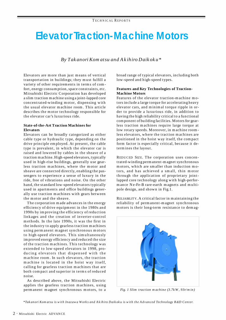
REDUCED SIZE. The corporation uses concen-trated-winding permanent-magnet synchronousmotors, which are smaller than induction mo-tors, and has achieved a small, thin motorthrough the application of proprietary joint-lapped core technology along with high-perfor-mance Ne-Fe-B rare-earth magnets and multi-pole design, and shown in Fig.1.
RELIABILITY. A critical factor in maintaining thereliability of permanent-magnet synchronousmotors is their long-term resistance to demag-
Fig. 1 Slim traction machine (3.7kW, 93r/min)
TECHNICAL REPORTS
· 3September 2003
netization. The temperature characteristics ofpermanent magnets are taken into consider-ation at the corporation, and the magnetic-circuitdesign and evaluation are performed taking intoaccount the usage-temperature regime of theequipment to provide a design with adequateresistance to demagnetization.
RIDE. Because torque ripple influences the rideexperienced by the passenger, the torque-ripplecharacteristics are important determinants ofthe quality of the elevator. On the other hand,because a smaller motor necessarily experiencesrelatively higher electric and magnetic loading,reducing the size of the motor tends to increasetorque ripple. Detailed magnetic analyses areperformed in pursuit of designs that suppresstorque ripple arising from various causes.
The slim traction-machine motor technologiesthat provide passengers with a luxurious ride areas follows.
Design for Torque-Ripple ReductionGenerally, designs that reduce torque ripple inpermanent-magnet synchronous motors reducemagnetic-drive resonance in the motor by opti-mizing the shapes of the permanent magnets.
They also investigate the coil arrangement (in-cluding the ratio of the numbers of poles andslots), and take advantage of skew, etc. In dis-tributed winding motors, which are used in high-speed/high-capacity applications, torque-ripplereductions closely matching theoretical valueshave been archived by these design processes.
However, slim motors use a concentratedwinding method, in which the motor is muchthinner and the diameter is larger. The result-ing effects of magnetic saturation and of manu-facturing tolerances have prevented torque ripplefrom being reduced by the theoretical values.Torque ripple can, however, be reduced by tak-ing magnetic saturation into account when de-signing the magnetic circuits, and analyzing themanufacturing tolerances and taking appropri-ate countermeasures.
1. Reducing the Impact of Magnetic SaturationSince reducing the thickness of the motor in-herently increases the electric loading on theconcentrated-winding stators, this easily leads
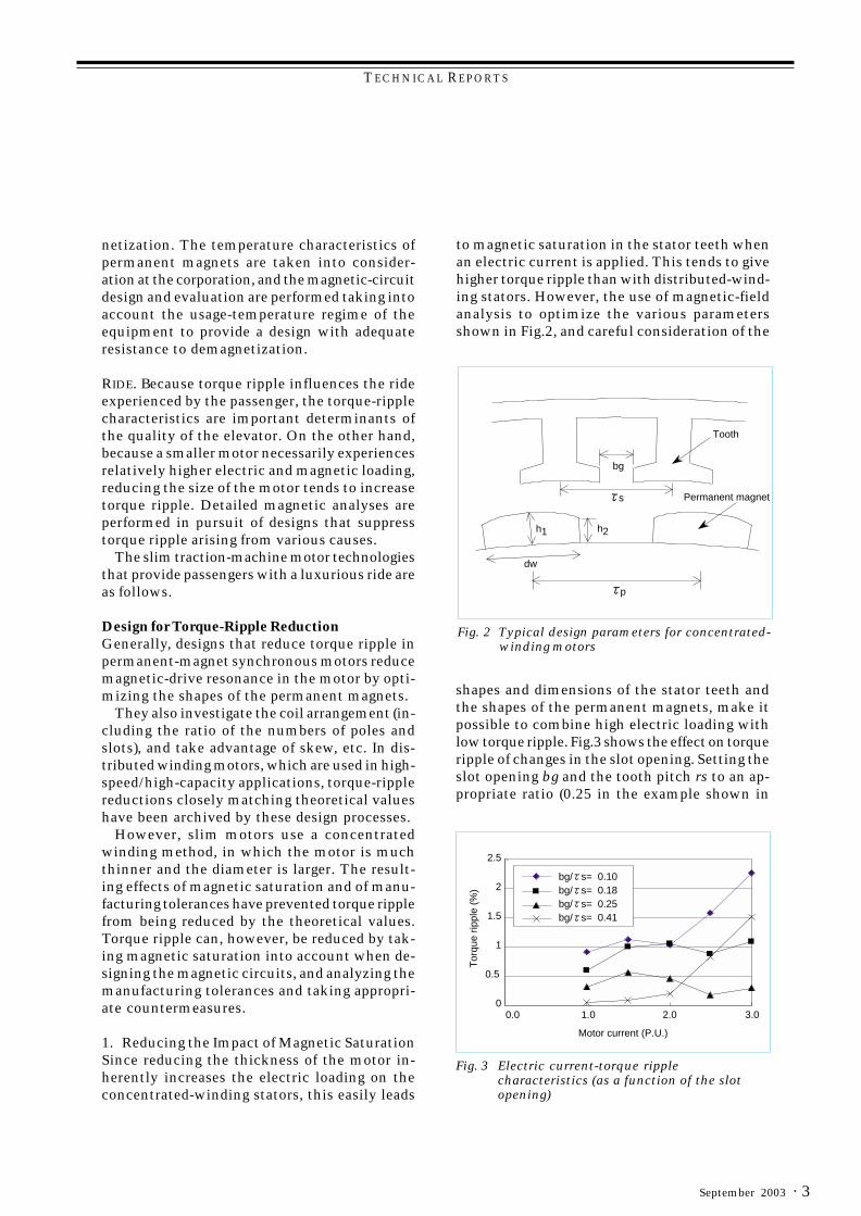
shapes and dimensions of the stator teeth andthe shapes of the permanent magnets, make itpossible to combine high electric loading withlow torque ripple. Fig.3 shows the effect on torqueripple of changes in the slot opening. Setting theslot opening bg and the tooth pitch rs to an ap-propriate ratio (0.25 in the example shown in
s
p
h2h1
bg
dw
Permanent magnet
Tooth
Fig. 2 Typical design parameters for concentrated-winding motors
Fig. 3 Electric current-torque ripplecharacteristics (as a function of the slotopening)
bg/ s= 0.10 bg/ s= 0.18bg/ s= 0.25bg/ s= 0.41
Tor
que
rippl
e (%
)
Motor current (P.U.)
0.0 1.0 2.0 3.00
1
1.5
2
2.5
0.5
to magnetic saturation in the stator teeth whenan electric current is applied. This tends to givehigher torque ripple than with distributed-wind-ing stators. However, the use of magnetic-fieldanalysis to optimize the various parametersshown in Fig.2, and careful consideration of the
TECHNICAL REPORTS
Mitsubishi Electric ADVANCE4 ·
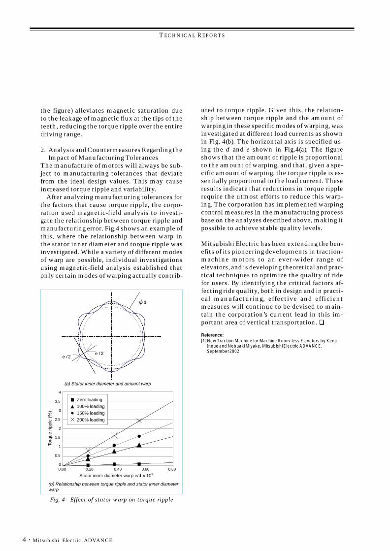
Fig. 4 Effect of stator warp on torque ripple
Zero loading
100% loading
150% loading
200% loading
Torq
ue r
ippl
e (%
)
4
3.5
2.5
1.5
0.5
3
2
1
00.00 0.20 0.40 0.60 0.80
(b) Relationship between torque ripple and stator inner diameter warp
(a) Stator inner diameter and amount warp
Stator inner diameter warp e/d 103
d
e / 2e / 2
the figure) alleviates magnetic saturation dueto the leakage of magnetic flux at the tips of theteeth, reducing the torque ripple over the entiredriving range.
2. Analysis and Countermeasures Regarding theImpact of Manufacturing Tolerances
The manufacture of motors will always be sub-ject to manufacturing tolerances that deviatefrom the ideal design values. This may causeincreased torque ripple and variability.
After analyzing manufacturing tolerances forthe factors that cause torque ripple, the corpo-ration used magnetic-field analysis to investi-gate the relationship between torque ripple andmanufacturing error. Fig.4 shows an example ofthis, where the relationship between warp inthe stator inner diameter and torque ripple wasinvestigated. While a variety of different modesof warp are possible, individual investigationsusing magnetic-field analysis established thatonly certain modes of warping actually contrib-
uted to torque ripple. Given this, the relation-ship between torque ripple and the amount ofwarping in these specific modes of warping, wasinvestigated at different load currents as shownin Fig. 4(b). The horizontal axis is specified us-ing the d and e shown in Fig.4(a). The figureshows that the amount of ripple is proportionalto the amount of warping, and that, given a spe-cific amount of warping, the torque ripple is es-sentially proportional to the load current. Theseresults indicate that reductions in torque ripplerequire the utmost efforts to reduce this warp-ing. The corporation has implemented warpingcontrol measures in the manufacturing processbase on the analyses described above, making itpossible to achieve stable quality levels.
Mitsubishi Electric has been extending the ben-efits of its pioneering developments in traction-machine motors to an ever-wider range ofelevators, and is developing theoretical and prac-tical techniques to optimize the quality of ridefor users. By identifying the critical factors af-fecting ride quality, both in design and in practi-cal manufacturing, effective and efficientmeasures will continue to be devised to main-tain the corporation’s current lead in this im-portant area of vertical transportation. ❑
Reference:[1]New Traction Machine for Machine Room-less Elevators by Kenji
Inoue and Nobuaki Miyake, Mitsubishi Electric ADVANCE,September 2002
TECHNICAL REPORTS
· 5September 2003
High-Efficiency Motors for Air-Conditioner Compressors
* Hitoshi Kawaguchi is with the Living Environment Systems Lab. and Tomoaki Oikawa is with Shizuoka Works
Although induction motors are used as the sourceof motive power in a variety of equipment used inthe home because of their durability, quietness,and low cost, they are increasingly being replacedby high-efficiency brushless DC motors due toincreased environmental concerns. In particular,because the power consumed by air conditionersand refrigerators accounts for some 40 percent ofhousehold power consumption, brushless DCmotors are being used in both of these appliances.
This article describes the efficiency-enhanc-ing technologies in brushless DC motors for roomair-conditioner compressors developed andimplemented by Mitsubishi Electric Corporation.
Brushless DC Motors for Room Air-Conditioner CompressorsBeginning in the air-conditioner season of 2001,the corporation completely revised the structureof the 4-pole distributed-winding interior perma-nent magnet (IPM) motor that had been used untilthen, successfully improving efficiency throughmoving to a 6-pole concentrated-winding IPMmotor with a jointed separated core structure.
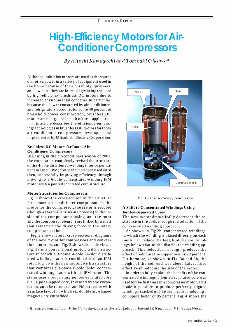
Motor Structures for CompressorsFig. 1 shows the cross-section of the structurefor a room air-conditioner compressor. In themotor for the compressor, the stator is secured(though a thermal-shrinking process) to the in-side of the compressor housing, and the rotorand the compressor element are linked by a shaftthat transmits the driving force to the rotarycompressor section.
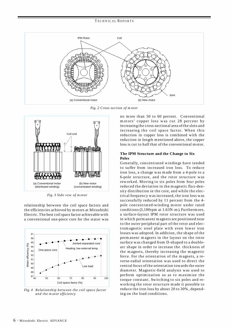
Fig. 2 shows lateral cross-sectional diagramsof the new motor for compressors and conven-tional motors, and Fig. 3 shows the side views.Fig. 3a is a conventional motor, with a struc-ture in which a 3-phase 4-pole 24-slot distrib-uted winding stator is combined with an IPMrotor. Fig. 3b is the new motor, with a structurethat combines a 3-phase 6-pole 9-slot concen-trated winding stator with an IPM rotor. Thestator uses a proprietary jointed-separated core(i.e., a joint-lapped core) invented by the corpo-ration, and the rotor uses an IPM structure witha surface layout in which six double arc-shapedmagnets are embedded.
By Hitoshi Kawaguchi and Tomoaki Oikawa*
A Shift to Concentrated Windings UsingJointed-Separated CoresThe new motor dramatically decreases the re-sistance in the coils through the selection of theconcentrated winding approach.
As shown in Fig.2b, concentrated windings,in which the winding is placed directly on eachtooth, can reduce the length of the coil wind-ings below that of the distributed winding ap-proach. This reduction in length produces theeffect of reducing the copper loss by 22 percent.Furthermore, as shown in Fig. 3a and 3b, theheight of the coil end was about halved, alsoeffective in reducing the size of the motor.
In order to fully exploit the benefits of the con-centrated windings, a jointed-separated core wasused for the first time in a compressor motor. Thismade it possible to produce perfectly alignedwindings, stacked up like drum cans, producing acoil space factor of 95 percent. Fig. 4 shows the
Fig. 1 Cross section of compressor
Compression unit
StatorShell
Rotor
TECHNICAL REPORTS
Mitsubishi Electric ADVANCE6 ·
relationship between the coil space factors andthe efficiencies achieved by motors at MitsubishiElectric. The best coil space factor achievable witha conventional one-piece core for the stator was
no more than 50 to 60 percent. Conventionalmotors’ copper loss was cut 28 percent byincreasing the cross-sectional area of the slots andincreasing the coil space factor. When thisreduction in copper loss is combined with thereduction in length mentioned above, the copperloss is cut to half that of the conventional motor.
The IPM Structure and the Change to SixPolesGenerally, concentrated windings have tendedto suffer from increased iron loss. To reduceiron loss, a change was made from a 4-pole to a6-pole structure, and the rotor structure wasreworked. Moving to six poles from four polesreduced the deviation in the magnetic flux-den-sity distribution in the core, and while the elec-trical frequency was increased, the iron loss wassuccessfully reduced by 11 percent from the 4-pole concentrated-winding motor under ratedconditions (3,180rpm at 1.63N-m). Furthermore,a surface-layout IPM rotor structure was usedin which permanent magnets are positioned nearto the outer peripheral part of the rotor and elec-tromagnetic steel plate with even lower ironlosses was adopted. In addition, the shape of thepermanent magnets in the layout on the rotorsurface was changed from D-shaped to a double-arc shape in order to increase the thickness ofthe magnets, thereby increasing the magneticforce. For the orientation of the magnets, a re-verse-radial orientation was used to direct thecentral focus of the orientation towards the outerdiameter. Magnetic-field analysis was used toperform optimization so as to maximize thetorque constant. Switching to six poles and re-working the rotor structure made it possible toreduce the iron loss by about 20 to 30%, depend-ing on the load conditions.
IPM Rotor Coil
Joint
(a) Conventional motor (b) New motor
Fig. 2 Cross section of motor
Coil end
(a) Conventional motor(distributed winding)
(b) New motor(concentrated winding)
Fig. 3 Side vew of motor
Mot
or e
ffici
ency
(%
)
Coil space factor (%)
One-piece core
Jointed-separated core
Heating: low external temp.
Low load
97
96
95
94
93
92
91
90
89
88
8740 50 60 70 80 90 100
Fig. 4 Relationship between the coil space factorand the motor efficiency
TECHNICAL REPORTS
· 7September 2003
Output (W)
Mot
or e
ffici
ency
(%)
6-pole joint-lappedcore concentrated winding
Rated condition
4-pole concentratedwinding motor
4-pole distributedwinding motor
Low load, low-speed condition
98
96
94
92
90
88
860 500 1000
Fig. 5 Comparison of motor efficiencies
Loss
(W
)
50
40
30
20
10
04-pole
(distributed winding)4-pole
(concentrated winding)6-pole joint-lapped core(concentrated winding)
Copper lossIron loss
Fig. 6 Comparison of motor losses
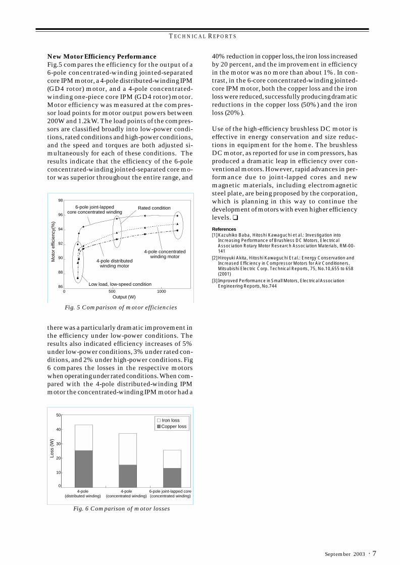
New Motor Efficiency PerformanceFig.5 compares the efficiency for the output of a6-pole concentrated-winding jointed-separatedcore IPM motor, a 4-pole distributed-winding IPM(GD4 rotor) motor, and a 4-pole concentrated-winding one-piece core IPM (GD4 rotor) motor.Motor efficiency was measured at the compres-sor load points for motor output powers between200W and 1.2kW. The load points of the compres-sors are classified broadly into low-power condi-tions, rated conditions and high-power conditions,and the speed and torques are both adjusted si-multaneously for each of these conditions. Theresults indicate that the efficiency of the 6-poleconcentrated-winding jointed-separated core mo-tor was superior throughout the entire range, and
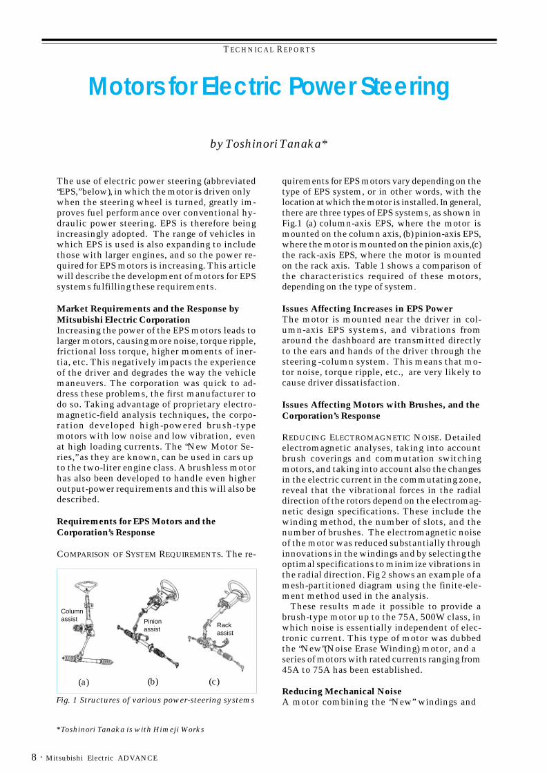
40% reduction in copper loss, the iron loss increasedby 20 percent, and the improvement in efficiencyin the motor was no more than about 1%. In con-trast, in the 6-core concentrated-winding jointed-core IPM motor, both the copper loss and the ironloss were reduced, successfully producing dramaticreductions in the copper loss (50%) and the ironloss (20%).
Use of the high-efficiency brushless DC motor iseffective in energy conservation and size reduc-tions in equipment for the home. The brushlessDC motor, as reported for use in compressors, hasproduced a dramatic leap in efficiency over con-ventional motors. However, rapid advances in per-formance due to joint-lapped cores and newmagnetic materials, including electromagneticsteel plate, are being proposed by the corporation,which is planning in this way to continue thedevelopment of motors with even higher efficiencylevels. ❑
References[1]Kazuhiko Baba, Hitoshi Kawaguchi et al.: Investigation into
Increasing Performance of Brushless DC Motors, ElectricalAssociation Rotary Motor Research Association Materials, RM-00-141
[2]Hiroyuki Akita, Hitoshi Kawaguchi Et al.: Energy Conservation andIncreased Efficiency in Compressor Motors for Air Conditioners,Mitsubishi Electric Corp. Technical Reports, 75, No.10,655 to 658(2001)
[3] Improved Performance in Small Motors, Electrical AssociationEngineering Reports, No.744
there was a particularly dramatic improvement inthe efficiency under low-power conditions. Theresults also indicated efficiency increases of 5%under low-power conditions, 3% under rated con-ditions, and 2% under high-power conditions. Fig6 compares the losses in the respective motorswhen operating under rated conditions. When com-pared with the 4-pole distributed-winding IPMmotor the concentrated-winding IPM motor had a
TECHNICAL REPORTS
Mitsubishi Electric ADVANCE8 ·
*Toshinori Tanaka is with Himeji Works
by Toshinori Tanaka*
Motors for Electric Power Steering
The use of electric power steering (abbreviated“EPS,” below), in which the motor is driven onlywhen the steering wheel is turned, greatly im-proves fuel performance over conventional hy-draulic power steering. EPS is therefore beingincreasingly adopted. The range of vehicles inwhich EPS is used is also expanding to includethose with larger engines, and so the power re-quired for EPS motors is increasing. This articlewill describe the development of motors for EPSsystems fulfilling these requirements.
Market Requirements and the Response byMitsubishi Electric CorporationIncreasing the power of the EPS motors leads tolarger motors, causing more noise, torque ripple,frictional loss torque, higher moments of iner-tia, etc. This negatively impacts the experienceof the driver and degrades the way the vehiclemaneuvers. The corporation was quick to ad-dress these problems, the first manufacturer todo so. Taking advantage of proprietary electro-magnetic-field analysis techniques, the corpo-ration developed high-powered brush-typemotors with low noise and low vibration, evenat high loading currents. The “New Motor Se-ries,” as they are known, can be used in cars upto the two-liter engine class. A brushless motorhas also been developed to handle even higheroutput-power requirements and this will also bedescribed.
Requirements for EPS Motors and theCorporation’s Response
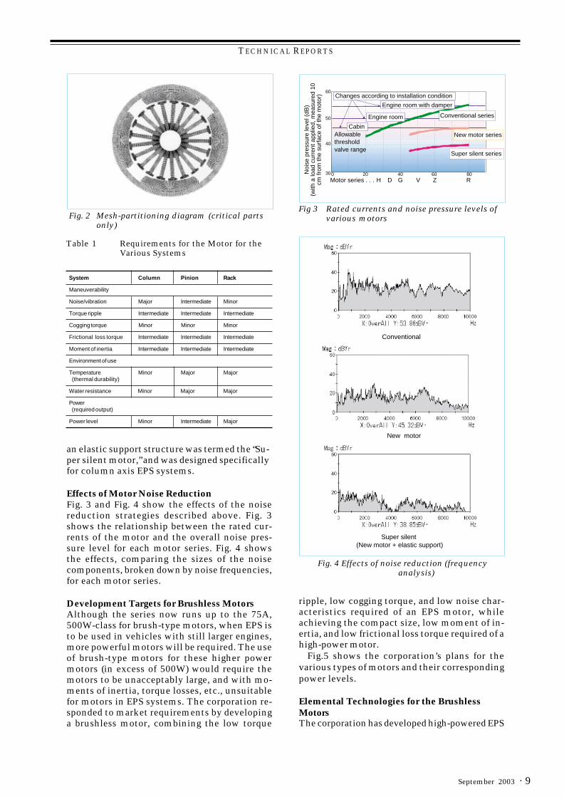
COMPARISON OF SYSTEM REQUIREMENTS. The re-
quirements for EPS motors vary depending on thetype of EPS system, or in other words, with thelocation at which the motor is installed. In general,there are three types of EPS systems, as shown inFig.1 (a) column-axis EPS, where the motor ismounted on the column axis, (b) pinion-axis EPS,where the motor is mounted on the pinion axis,(c)the rack-axis EPS, where the motor is mountedon the rack axis. Table 1 shows a comparison ofthe characteristics required of these motors,depending on the type of system.
Issues Affecting Increases in EPS PowerThe motor is mounted near the driver in col-umn-axis EPS systems, and vibrations fromaround the dashboard are transmitted directlyto the ears and hands of the driver through thesteering -column system. This means that mo-tor noise, torque ripple, etc., are very likely tocause driver dissatisfaction.
Issues Affecting Motors with Brushes, and theCorporation’s Response
REDUCING ELECTROMAGNETIC NOISE. Detailedelectromagnetic analyses, taking into accountbrush coverings and commutation switchingmotors, and taking into account also the changesin the electric current in the commutating zone,reveal that the vibrational forces in the radialdirection of the rotors depend on the electromag-netic design specifications. These include thewinding method, the number of slots, and thenumber of brushes. The electromagnetic noiseof the motor was reduced substantially throughinnovations in the windings and by selecting theoptimal specifications to minimize vibrations inthe radial direction. Fig 2 shows an example of amesh-partitioned diagram using the finite-ele-ment method used in the analysis.
These results made it possible to provide abrush-type motor up to the 75A, 500W class, inwhich noise is essentially independent of elec-tronic current. This type of motor was dubbedthe “New”(Noise Erase Winding) motor, and aseries of motors with rated currents ranging from45A to 75A has been established.
Reducing Mechanical NoiseA motor combining the “New” windings and
Columnassist Pinion
assistRackassist
Fig. 1 Structures of various power-steering systems
(a) (b) (c)
TECHNICAL REPORTS
· 9September 2003
an elastic support structure was termed the “Su-per silent motor,” and was designed specificallyfor column axis EPS systems.
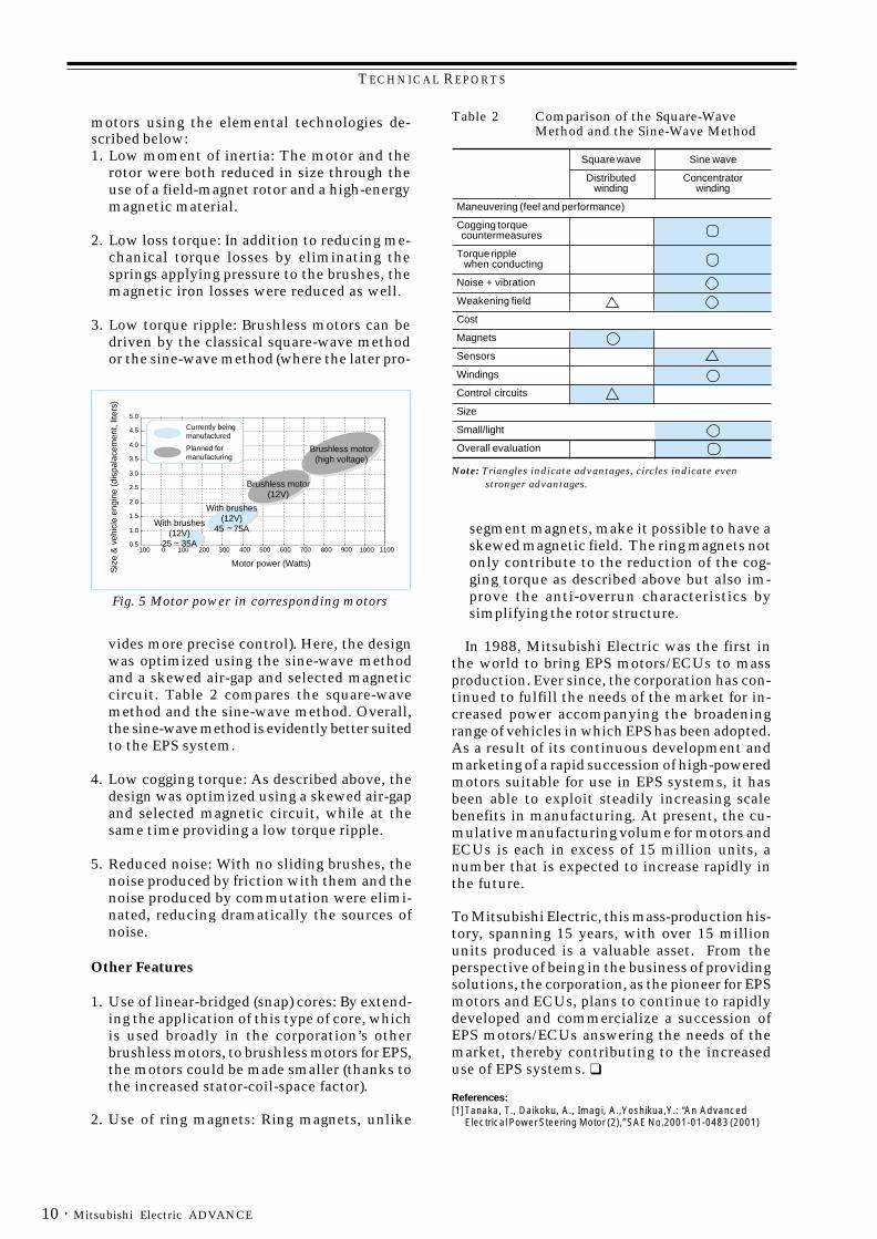
Effects of Motor Noise ReductionFig. 3 and Fig. 4 show the effects of the noisereduction strategies described above. Fig. 3shows the relationship between the rated cur-rents of the motor and the overall noise pres-sure level for each motor series. Fig. 4 showsthe effects, comparing the sizes of the noisecomponents, broken down by noise frequencies,for each motor series.
Development Targets for Brushless MotorsAlthough the series now runs up to the 75A,500W-class for brush-type motors, when EPS isto be used in vehicles with still larger engines,more powerful motors will be required. The useof brush-type motors for these higher powermotors (in excess of 500W) would require themotors to be unacceptably large, and with mo-ments of inertia, torque losses, etc., unsuitablefor motors in EPS systems. The corporation re-sponded to market requirements by developinga brushless motor, combining the low torque
Table 1 Requirements for the Motor for theVarious Systems
System Column Pinion Rack
Maneuverability
Noise/vibration Major Intermediate Minor
Torque ripple Intermediate Intermediate Intermediate
Cogging torque Minor Minor Minor
Frictional loss torque Intermediate Intermediate Intermediate
Moment of inertia Intermediate Intermediate Intermediate
Environment of use
Temperature Minor Major Major(thermal durability)
Water resistance Minor Major Major
Power(required output)
Power level Minor Intermediate Major
Fig 3 Rated currents and noise pressure levels ofvarious motors
Changes according to installation condition
Engine room with damper
Engine room
CabinAllowablethresholdvalve range
Noi
se p
ress
ure
leve
l (dB
)(w
ith a
load
cur
rent
app
lied,
mea
sure
d 10
cm fr
om th
e su
rfac
e of
the
mot
or) 60
60
40
50
300 20 40 80Motor series . . . RZVGDH
Conventional series
New motor series
Super silent series
Fig. 4 Effects of noise reduction (frequencyanalysis)
Conventional
New motor
Super silent (New motor + elastic support)
ripple, low cogging torque, and low noise char-acteristics required of an EPS motor, whileachieving the compact size, low moment of in-ertia, and low frictional loss torque required of ahigh-power motor.
Fig.5 shows the corporation’s plans for thevarious types of motors and their correspondingpower levels.
Elemental Technologies for the BrushlessMotorsThe corporation has developed high-powered EPS
Fig. 2 Mesh-partitioning diagram (critical partsonly)
TECHNICAL REPORTS
Mitsubishi Electric ADVANCE10 ·
0.5
1.0
1.5
2.0
2.5
3.0
3.5
4.0
4.5
5.0
Currently beingmanufactured
Planned formanufacturing
Siz
e &
veh
icle
eng
ine
(dis
pala
cem
ent,
liter
s)
0 100-100 200 300 400 500 600 700 800 900 1000 1100
Brushless motor(high voltage)
Brushless motor(12V)
With brushes(12V)
25 35A
With brushes(12V)
45 75A
Motor power (Watts)
Fig. 5 Motor power in corresponding motors
Note: Triangles indicate advantages, circles indicate even stronger advantages.
Table 2 Comparison of the Square-WaveMethod and the Sine-Wave Method
segment magnets, make it possible to have askewed magnetic field. The ring magnets notonly contribute to the reduction of the cog-ging torque as described above but also im-prove the anti-overrun characteristics bysimplifying the rotor structure.
In 1988, Mitsubishi Electric was the first inthe world to bring EPS motors/ECUs to massproduction. Ever since, the corporation has con-tinued to fulfill the needs of the market for in-creased power accompanying the broadeningrange of vehicles in which EPS has been adopted.As a result of its continuous development andmarketing of a rapid succession of high-poweredmotors suitable for use in EPS systems, it hasbeen able to exploit steadily increasing scalebenefits in manufacturing. At present, the cu-mulative manufacturing volume for motors andECUs is each in excess of 15 million units, anumber that is expected to increase rapidly inthe future.
To Mitsubishi Electric, this mass-production his-tory, spanning 15 years, with over 15 millionunits produced is a valuable asset. From theperspective of being in the business of providingsolutions, the corporation, as the pioneer for EPSmotors and ECUs, plans to continue to rapidlydeveloped and commercialize a succession ofEPS motors/ECUs answering the needs of themarket, thereby contributing to the increaseduse of EPS systems. ❑
References:[1]Tanaka, T., Daikoku, A., Imagi, A.,Yoshikua,Y.: “An Advanced
Electrical Power Steering Motor (2),” SAE No.2001-01-0483 (2001)
motors using the elemental technologies de-scribed below:1. Low moment of inertia: The motor and the
rotor were both reduced in size through theuse of a field-magnet rotor and a high-energymagnetic material.
2. Low loss torque: In addition to reducing me-chanical torque losses by eliminating thesprings applying pressure to the brushes, themagnetic iron losses were reduced as well.
3. Low torque ripple: Brushless motors can bedriven by the classical square-wave methodor the sine-wave method (where the later pro-
vides more precise control). Here, the designwas optimized using the sine-wave methodand a skewed air-gap and selected magneticcircuit. Table 2 compares the square-wavemethod and the sine-wave method. Overall,the sine-wave method is evidently better suitedto the EPS system.
4. Low cogging torque: As described above, thedesign was optimized using a skewed air-gapand selected magnetic circuit, while at thesame time providing a low torque ripple.
5. Reduced noise: With no sliding brushes, thenoise produced by friction with them and thenoise produced by commutation were elimi-nated, reducing dramatically the sources ofnoise.
Other Features
1. Use of linear-bridged (snap) cores: By extend-ing the application of this type of core, whichis used broadly in the corporation’s otherbrushless motors, to brushless motors for EPS,the motors could be made smaller (thanks tothe increased stator-coil-space factor).
2. Use of ring magnets: Ring magnets, unlike
Square wave Sine wave
Distributed Concentratorwinding winding
Maneuvering (feel and performance)
Cogging torquecountermeasures
Torque ripple when conducting
Noise + vibration
Weakening field
Cost
Magnets
Sensors
Windings
Control circuits
Size
Small/light
Overall evaluation
TECHNICAL REPORTS
· 11September 2003
*Hideo Terasawa is with the Transportation Systems Center.
by Hideo Terasawa*
High-Efficiency Motors for RailTraction Engines
Given the major role they play in heavy trans-portation, railroads are an indispensable part ofour lives. With this mode of transportation be-ing reassessed from the perspective of globalenvironmental protection, demand in the elec-tric railway market is as strong as ever. Thesetrains are powered by electric motors; this ar-ticle will describe electric motors for railway usefrom the perspective of improved efficiency andreduced maintenance.
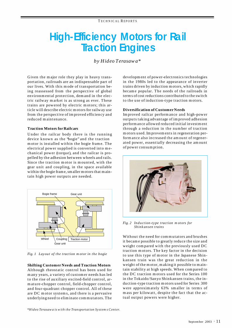
Traction Motors for RailcarsUnder the railcar body there is the runningdevice known as the “bogie” and the tractionmotor is installed within the bogie frame. Theelectrical power supplied is converted into me-chanical power (torque), and the railcar is pro-pelled by the adhesion between wheels and rails.Since the traction motor is mounted, with thegear unit and coupling, in the space availablewithin the bogie frame, smaller motors that main-tain high power outputs are needed.
Fig. 1 Layout of the traction motor in the bogie
Shifting Customer Needs and Traction MotorsAlthough rheostatic control has been used formany years, a variety of customer needs has ledto the rise of auxiliary excited-field control, ar-mature-chopper control, field-chopper control,and four-quadrant chopper control. All of theseare DC motor systems, and there is a pervasiveunderlying need to eliminate commutators. The
development of power-electronics technologiesin the 1980s led to the appearance of invertertrains driven by induction motors, which rapidlybecame popular. The needs of the railroads interms of cost reductions contributed to the switchto the use of induction-type traction motors.
Diversification of Customer NeedsImproved railcar performance and high-poweroutputs taking advantage of improved adhesionperformance allowed reduced initial investmentthrough a reduction in the number of tractionmotors used. Improvements in regeneration per-formance also increased the amount of regener-ated power, essentially decreasing the amountof power consumption.
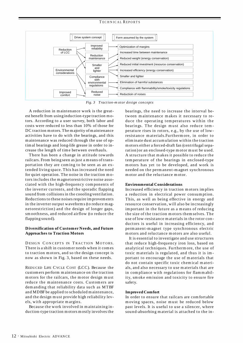
Fig. 2 Induction-type traction motors forShinkansen trains
Without the need for commutators and brushesit became possible to greatly reduce the size andweight compared with the previously used DCtraction motors. The key factor in the decisionto use this type of motor in the Japanese Shin-kansen train was the great reduction in theweight of the motor, making it possible to main-tain stability at high speeds. When compared tothe DC traction motors used for the Series 100in the Tokaido/Sanyo Shinkansen trains, the in-duction-type traction motors used for Series 300were approximately 63% smaller in terms ofmass per kilowatt, despite the fact that the ac-tual output powers were higher.
Bogie frame Gear unit
Wheel
Gear unit
Coupling Traction motor
TECHNICAL REPORTS
Mitsubishi Electric ADVANCE12 ·
A reduction in maintenance work is the great-est benefit from using induction-type traction mo-tors. According to a user survey, both labor andcosts were reduced to less than 10% of those forDC traction motors. The majority of maintenanceactivities have to do with the bearings, and thismaintenance was reduced through the use of op-timal bearings and long-life grease in order to in-crease the length of time between overhauls.
There has been a change in attitude towardsrailcars. From being seen as just a means of trans-portation they are coming to be seen as an ex-tended living space. This has increased the needfor quiet operation. The noise in the traction mo-tors includes the magnetorestrictive noise asso-ciated with the high-frequency components ofthe inverter currents, and the sporadic flappingsound from collisions in the coooling ventilation.Reductions to these noises require improvementsin the inverter output waveforms (to reduce mag-netorestriction) and the design of longer gaps,smoothness, and reduced airflow (to reduce theflapping sound).
Diversification of Customer Needs, and FutureApproaches to Traction Motors
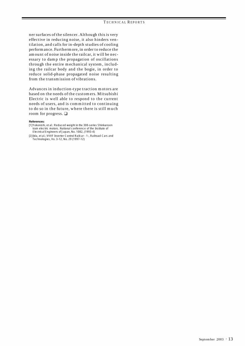
DESIGN CONCEPTS IN TRACTION MOTORS.There is a shift in customer needs when it comesto traction motors, and so the design concept isnow as shown in Fig. 3, based on these needs.
REDUCED LIFE CYCLE COST (LCC). Because thecustomers perform maintenance on the tractionmotors for the railcars, the motor design mustreduce the maintenance costs. Customers aredemanding that reliability data such as MTBFand MDBF be applied to scheduled maintenance,and the design must provide high reliability lev-els, with appropriate margins.
Because the work involved in maintaining in-duction-type traction motors mostly involves the
bearings, the need to increase the interval be-tween maintenance makes it necessary to re-duce the operating temperatures within thebearings. The design must also reduce tem-perature rises in rotors, e.g., by the use of low-resistance materials.Furthermore, in order toeliminate dust accumulation within the tractionmotors either a forced-draft fan (centrifugal sepa-ration) or an enclosed-type motor must be used.A structure that makes it possible to reduce thetemperature of the bearings in enclosed-typemotors has yet to be developed, and work isneeded on the permanent-magnet synchronousmotor and the reluctance motor.
Environmental ConsiderationsIncreased efficiency in traction motors impliesa reduction in electrical power consumption.This, as well as being effective in energy andresource conservation, will also be increasinglyimportant in the future as a means of reducingthe size of the traction motors themselves. Theuse of low-resistance materials in the rotor con-ductors is useful in increasing efficiency, andpermanent-magnet type synchronous electricmotors and reluctance motors are also useful.
It is essential to investigate and use structuresthat reduce high-frequency iron loss, based onanalytical techniques. Furthermore, the use oftoxic materials is regulated, and thus it is im-portant to encourage the use of materials thatdo not contain specific toxic chemical materi-als, and also necessary to use materials that arein compliance with regulations for flammabil-ity, smoke emission and toxicity to ensure firesafety.
Improved ComfortIn order to ensure that railcars are comfortablemoving spaces, noise must be reduced belowpast levels. It is useful to use a silencer, wheresound-absorbing material is attached to the in-
Fig. 3 Traction-motor design concepts
Drive system concept Form assumed by the system
Reduction of LCC
Environmental considerations
Improvedcomfort
Improved reliability
Reduction maintenance
Smallerand
lighter
Compliancewith
environmentalregulations
Reducednoise
Optimization of margins
Increased time between maintenance
Reduced weight (energy conservation)
Reduced initial investment (resource conservation)
Increased efficiency (energy conservation)
Smaller and lighter
Elimination of harmful substances
Compliance with flammability/smoke/toxicity regulations
Reductioin of noises
TECHNICAL REPORTS
· 13September 2003
ner surfaces of the silencer. Although this is veryeffective in reducing noise, it also hinders ven-tilation, and calls for in-depth studies of coolingperformance. Furthermore, in order to reduce theamount of noise inside the railcar, it will be nec-essary to damp the propagation of oscillationsthrough the entire mechanical system, includ-ing the railcar body and the bogie, in order toreduce solid-phase propagated noise resultingfrom the transmission of vibrations.
Advances in induction-type traction motors arebased on the needs of the customers. MitsubishiElectric is well able to respond to the currentneeds of users, and is committed to continuingto do so in the future, where there is still muchroom for progress. ❑
References:[1]Yokonishi, et al.: Reduced weight in the 300-series Shinkansen
train electric motors. National conference of the Institute ofElectrical Engineers of Japan, No. 1082, (1993-4)
[2] Iida, et al.; VVVF Inverter Control Railcar - 1-, Railroad Cars andTechnologies, Vo. 3-12, No. 29 (1997-12)
TECHNICAL REPORTS
Mitsubishi Electric ADVANCE14 ·
*Hiromitsu Tatsumi and Hitoshi Yoshino are with Nagoya Works.
by Hiromitsu Tatsumi and Hitoshi Yoshino*
High-Efficiency Industrial Motors
Since the operating principle for induction mo-tors was discovered in the 19th century, induc-tion motors have been the principal source ofmotive power in industry, and have undergonecontinual refinement, becoming smaller, lighter,and better in many ways, with higher perfor-mance. However, the requirements for improvedefficiency in motors have become even morestringent in recent years, given acceleratingmovements in energy conservation in order toprotect the environment (including the avoid-ance of global warming) and concerns regard-ing the depletion of petrochemical energyresources.
Mitsubishi Electric Corporation has developeda series of high-efficiency motors fulfilling theefficiency requirements of both the JIS standardsin Japan and the Energy Policy Act of 1992 inthe United States, and was the first Japanesemanufacturer to earn a conformance certificatenumber from the United States Department ofEnergy. This article discusses trends in three-phase motors and describes the high-efficiencymotors at the corporation and technologies usedto achieve these efficiencies.
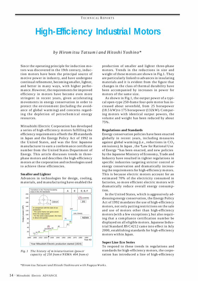
Smaller and LighterAdvances in technologies for design, cooling,materials, and manufacturing have enabled the
production of smaller and lighter three-phasemotors. Trends in the reductions in size andweight of these motors are shown in Fig.1. Theyare particularly linked to advances in insulatingmaterials and it is evident from the figure thatchanges in the class of thermal durability havebeen accompanied by increases in power formotors of the same size.
As shown in Fig.1, the output power of a typi-cal open-type 250-frame four-pole motor has in-creased about sevenfold, from 25 horsepower(18.5 kW) to 175 horsepower (132kW). Compar-ing motors with identical output powers, thevolume and weight has been reduced by about75%.
Regulations and StandardsEnergy conservation policies have been enactedglobally in recent years, including measuresagainst global warming (i.e., reductions in CO2
emissions). In Japan , the “Law for Rational Useof Energy “ has been enacted, and new policiesby the Japanese Ministry of Economy, Trade andIndustry have resulted in tighter regulations inspecific industries targeting stricter control ofenergy conservation and dramatically increas-ing the requirements for high-efficiency motors.This is because electric motors account for anestimated 70% of the electricity consumed infactories, so more efficient electric motors willdramatically reduce overall energy consump-tion.
In the United States, which is aggressively ad-dressing energy conservation, the Energy PolicyAct of 1992 mandates the use of high-efficiencymotors, not only putting restrictions on the saleand use of motors other than high-efficiencymotors (with a few exceptions ), but also requir-ing that a compliance certification number bedisplayed on all eligible motors. Japanese Indus-trial Standard JIS C4212 came into effect in July2000, establishing standards for high-efficiencymotors within Japan.
Super Line Eco SeriesTo respond to these trends in regulations andstandards for high-efficiency motors, the corpo-ration has introduced a line of high-efficiency
Fig. 1 The history of miniaturization (powercapacity of 250 frame/NEMA 404 frame)
200
180
160
140
120
100
80
60
40
20
Out
put p
ower
(H
P)
1890 1900 1910 1920 1930 1940 1950 1960 1970 1980 1990
10inch
Year Mitsubishi Electric production started (1924)
Year AD
7.510 15
20
2530
4050
60
75
120
175 (132KW)
100 (75KW)
(18.5KW)
Transitions in the Thermal DurabirityClass in the JIS Standards A E E, B, F
In comparison with the start of our production:- The same frame size gives seven times the output power - For the same output power, the mass is about one quarter.
JIS
NEMA
TECHNICAL REPORTS
· 15September 2003
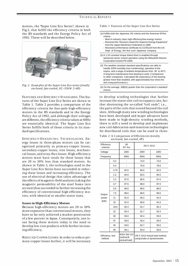
motors, the “Super Line Eco Series”, shown inFig.2, that fulfill the efficiency criteria in boththe JIS standards and the Energy Policy Act of1992. These will be described below.
Fig. 2 Examples of the Super Line Eco series (totallyenclosed, fan-cooled, 02.~55kW 2~6P)
FEATURES AND EFFICIENCY STANDARDS. The fea-tures of the Super Line Eco Series are shown inTable 1. Table 2 provides a comparison of theefficiency criteria for four-pole high-efficiencymotors in the JIS standards and in the EnergyPolicy Act of 1992, and although their voltagesare different, the efficiency criteria values at 60Hzare essentially identical. The Super Line EcoSeries fulfills both of these criteria in its stan-dard specifications.
EFFICIENCY-ENHANCING TECHNOLOGIES. En-ergy losses in three-phase motors can be cat-egorized primarily as primary-copper losses,secondary-copper losses, iron losses, mechani-cal losses, and stray-flux losses. High-efficiencymotors must have totals for these losses thatare 20 to 30% less than standard motors. Asshown in Table 3, the technologies used in theSuper Line Eco Series have succeeded in reduc-ing these losses and increasing efficiency. Theuse of electrical design that takes advantage ofthe effects of magnetic-field analysis ( taking themagnetic permeability of the steel frame intoaccount) has succeeded in further increasing theefficiency of conventional high-efficiency mo-tors, with identical or smaller stator sizes.
Issues in High-Efficiency MotorsBecause high-efficiency motors are 20 to 30%more expensive than conventional motors, theyhave so far only achieved a market penetrationof a few percent in Japan. Consequently, one is-sue facing these motors today is the need todevelop low-cost products while further increas-ing efficiency.
REDUCED COPPER LOSSES. In order to reduce pri-mary-copper losses further, it will be necessary
Table 1 Features of the Super Line Eco Series
(1) Fulfills both the Japanese JIS criteria and the American EPActcriteria- Best-in-industry class high-efficiency/low-energy motors.- Received the “Directors Award for Superior Energy Equipment”
from the Japan Machinery Federation in 1999.- Received conformance certificate no.CC0012A from the US
Dept. of Energy, the first such Japanese company.
(2) A 1:10 constant torque linked drive is enabled throughadvanced vector control operation using the Mitsubishi ElectricCorporation inverter FR-A500.
(3) The weather resistant standard specifications are able tohandle 100% humidity (non-condensing), operation in thetropics, and a range of ambient temperatures from -30 to 40°C.A long-term maintenance-free bearing is used. ( Comparisonto other companies: Calculated life expectancy of the bearinggrease more than doubled, with approximately four times theanti-creep performance.)
(4) On the average, 3dB(A) quieter than the corporation’s standardmotors.
to develop winding technologies that furtherincrease the stator-slot coil-occupancy rate, fur-ther shortening the so-called “coil ends”, i.e.,the parts of the coils that extend beyond the coilslots. Although many new winding technologieshave been developed and major advances havebeen made in high-density winding methods,there is still a need to develop and implementnew coil-fabrication-and-insertion technologiesfor distributed coils that can be used in three-
Table 2 A Comparison of Efficiencies (totallyenclosed, fan-cooled, 4P)
Efficiency US JIS C 4212criterion EP Act
Voltage 230V 200V 220V
Frequency 60Hz 50Hz 60Hz
0.2 - 72.0 74.0
0.4 - 76.0 78.0
0.75 82.5 80.5 82.5
1.5 84.0 82.5 84.0
2.2 87.5 85.5 87.0
3.7 87.5 86.0 87.5
5.5 89.5 88.5 89.5
Output 7.5 89.5 88.5 89.5
power 11 91.0 90.2 91.0
(kW)
15 91.0 90.6 91.0
18.5 92.4 91.7 92.4
22 92.4 91.7 92.4
30 93.0 92.4 93.0
37 93.0 92.4 93.0
45 93.6 92.7 93.0
55 94.1 93.3 93.6
Efficiency test IEEE Std 112 JIS C 4212 Actual load method,method method B using brake or dynamometer.
(actual load)
TECHNICAL REPORTS
Mitsubishi Electric ADVANCE16 ·
phase motors to further reduce primary-copperloss. Reductions in secondary-copper losses willrequire efforts to increase the cross-sectionalarea of the motor slots and to decrease the re-sistance inherent in the conductive materials.The development and application of aluminummelt-forging technology instead of cast alumi-num conductors in order to obtain higher den-sity conductors with fewer voids, and thedevelopment of manufacturing technologies forcopper conductors, which have lower inherentresistances than aluminum conductors, are twoviable approaches.
STRAY-FLUX LOSSES. Stray-flux losses account forabout 10% of all motor losses. These losses in-crease with the motor load, and have been diffi-cult to analyze quantitatively in the past,because it has been difficult to analyze quanti-tatively, through considering the fundamentalfrequency copper alone, the high-frequency com-ponents that increase with the load. Recent ad-vances in magnetic-field analysis technologieshave made it possible to separate the high-fre-quency losses into iron-related and copper-relatedlosses, making it possible to analyze with highprecision the losses that occur at the stators,the rotors, the gaps, etc. When combined withhigh-precision losses-measurement technologies,this makes it possible to analyze stray-flux lossesquantitatively and to validate the analytical re-sults experimentally, producing major reductionsin stray-flux losses that previously relied exclu-sively on empirical methods. This offers goodprospects of further cost reductions.
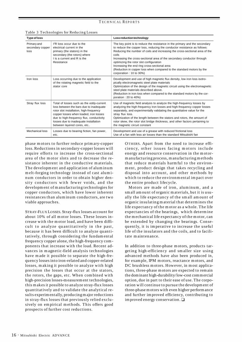
Table 3 Technologies for Reducing LossesType of loss Loss reduction technology
Primary and I2R loss occur due to the The key point is to reduce the resistance in the primary and the secondarysecondary copper electrical current in the to reduce the copper loss, reducing the conductor resistance as follows:loss primary (the stators) in the Reducing the number of coils and increasing the cross-sectional area of the
secondary (the rotors) where coilsI is a current and R is the Increasing the cross-sectional area of the secondary conductor throughResistance optimizing the rotor slot configuration
Increasing the end ring cross-sectional area(Reduction in copper loss when compared to the standard motors by thecorporation : 10 to 30%)
Iron loss Loss occurring due to the application Development and use of high magnetic flux density, low iron loss isotro-of the rotating magnetic field to the pically electromagnetic steel plate materialsstator core Optimization of the design of the magnetic circuit using the electromagnetic
steel plate materials described above.(Reduction in iron loss when compared to the standard motors by the cor-poration : 20 to 40%)
Stray flux loss Total of losses such as the eddy-current Use of magnetic field analysis to analyze the high-frequency losses byloss between the bars due to inadequate analyzing the high-frequency iron losses and high-frequency copper lossesrotor slot installation, high-frequency separately, and experimentally validating the quantitative value for thecopper losses when loaded, iron losses stray flux loss.due to high-frequency flux, conductivity Optimization of the length between the stators and rotors, the amount oflosses due to inadequate installation rotor skew, the rotor slot bridge thickness, and other factors pertaining tobetween layered cores, etc.. the magnetic circuit constant
Mechanical loss Losses due to bearing fiction, fan power, Development and use of a grease with reduced frictional lossetc. Use of a fan with less air losses than the standard Mitsubishi fan
OTHERS. Apart from the need to increase effi-ciency, other issues facing motors includeenergy and resource conservation in the motor-manufacturing process, manufacturing methodsthat reduce materials harmful to the environ-ment, product design that takes recycling anddisposal into account, and other methods bywhich to reduce the environmental impact overthe entire product lifecycle.
Motors are made of iron, aluminum, and asmall amount of organic materials, but it is usu-ally the life expectancy of the small amount oforganic insulating material that determines thelife expectancy of the motor as a whole. The lifeexpectancies of the bearings, which determinethe mechanical life expectancy of the motor, canbe extended by changing the bearings. Conse-quently, it is imperative to increase the usefullife of the insulators and the coils, and to facili-tate maintenance.
In addition to three-phase motors, products tar-geting high-efficiency and smaller size usingadvanced methods have also been produced in,for example, IPM motors, reactance motors, andDC brushless motors. However, in most applica-tions, three-phase motors are expected to remainthe dominant high-durability/low-cost commercialoption, due in part to their ease of use. The corpo-ration will continue to pursue the development ofthree-phase motors with even higher performanceand further improved efficiency, contributing toimproved energy conservation. ❑
TECHNICAL REPORTS
· 17September 2003
*Kazuyuki Kawashima and Akihiro Shimada are with Nagoya Works
By Kazuyuki Kawashima and Akihiro Shimada*
Spindle Motors for Machine Tools
Spindle motors for machine tools are a type ofservo motor characterized by emphasis on high-speed performance. With the increases in speedneeded to support advances in high-speed ma-chining centers, spindle motors for machine toolswith a maximum speed of up to 70,000rpm havebeen marketed. From the perspective of high-precision machining, there have been advancesin technologies developed to reduce the amountof heat produced. Also, with increases in theefficiency of induction motors, long used as con-ventional AC spindle motors, the advent of in-ternal permanent-magnet motors has expandedthe range of options for increased efficiency. This article discusses (1) spindle motors thatuse ultrahigh-speed induction motors to reachspeeds of 70,000rpm, (2) spindle motors that usehigh-speed/high-efficiency induction motors toreduce electrical losses in the high-speed do-main by 50%, and (3) spindle motors that useinternal permanent-magnet motors to achievehigh efficiencies in the high-torque domain.
Ultrahigh-Speed Built-In Induction-TypeSpindle MotorsIn recent years, a focus on increasing the effi-ciency of machine tools has seen rapid advancesin technologies to speed up the spindles in, forexample, machining centers. Mitsubishi Elec-tric Corporation has been developing ultra high-speed built-in induction-type spindle motorssince 1995, and has marketed a spindle motorwith a maximum speed of 70,000rpm.
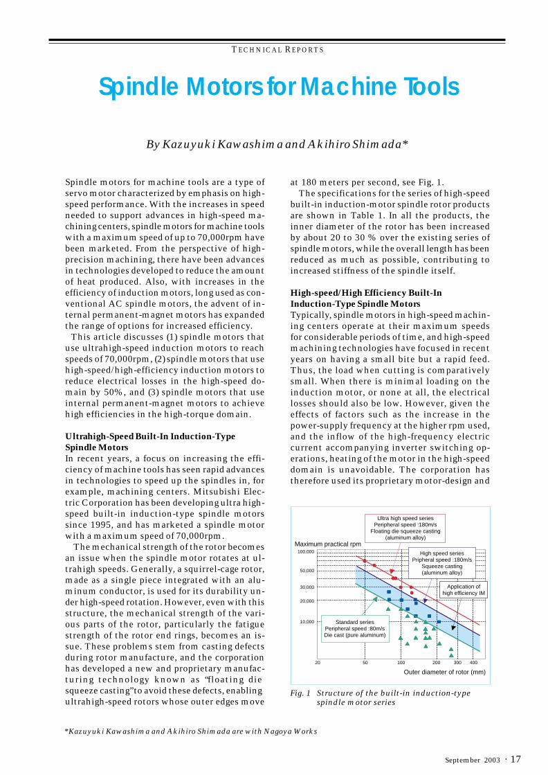
The mechanical strength of the rotor becomesan issue when the spindle motor rotates at ul-trahigh speeds. Generally, a squirrel-cage rotor,made as a single piece integrated with an alu-minum conductor, is used for its durability un-der high-speed rotation. However, even with thisstructure, the mechanical strength of the vari-ous parts of the rotor, particularly the fatiguestrength of the rotor end rings, becomes an is-sue. These problems stem from casting defectsduring rotor manufacture, and the corporationhas developed a new and proprietary manufac-turing technology known as “floating diesqueeze casting” to avoid these defects, enablingultrahigh-speed rotors whose outer edges move
at 180 meters per second, see Fig. 1.The specifications for the series of high-speed
built-in induction-motor spindle rotor productsare shown in Table 1. In all the products, theinner diameter of the rotor has been increasedby about 20 to 30 % over the existing series ofspindle motors, while the overall length has beenreduced as much as possible, contributing toincreased stiffness of the spindle itself.
High-speed/High Efficiency Built-InInduction-Type Spindle MotorsTypically, spindle motors in high-speed machin-ing centers operate at their maximum speedsfor considerable periods of time, and high-speedmachining technologies have focused in recentyears on having a small bite but a rapid feed.Thus, the load when cutting is comparativelysmall. When there is minimal loading on theinduction motor, or none at all, the electricallosses should also be low. However, given theeffects of factors such as the increase in thepower-supply frequency at the higher rpm used,and the inflow of the high-frequency electriccurrent accompanying inverter switching op-erations, heating of the motor in the high-speeddomain is unavoidable. The corporation hastherefore used its proprietary motor-design and
Fig. 1 Structure of the built-in induction-typespindle motor series
Ultra high speed seriesPeripheral speed :180m/s
Floating die squeeze casting(aluminum alloy)
High speed seriesPripheral speed :180m/s
Squeeze casting(aluminum alloy)
Application ofhigh efficiency IM
Standard seriesPeripheral speed :80m/sDie cast (pure aluminum)
Maximum practical rpm100,000
50,000
30,000
20,000
10,000
20 50 100 200 300 400
Outer diameter of rotor (mm)
TECHNICAL REPORTS
Mitsubishi Electric ADVANCE18 ·
manufacturing processes to develop a high-ef-ficiency induction-type spindle motor, where theelectrical losses in the high-speed domain arehalf those of a conventional high-speed spindlemotor. Because the main motors for today’shigh-speed machining form a series of high-speed motors, the corporation has increased thespeed and the efficiency of this entire series,see Fig. 1.
ModelFramesize
Outputpower (kW)(cont./30-
min. rating
Speed ofrotation
(base/max. rpm)
Principal dimensions (mm)
Statorouter diam.
Rotorouter diam.
Rotorinner diam.
Corelength
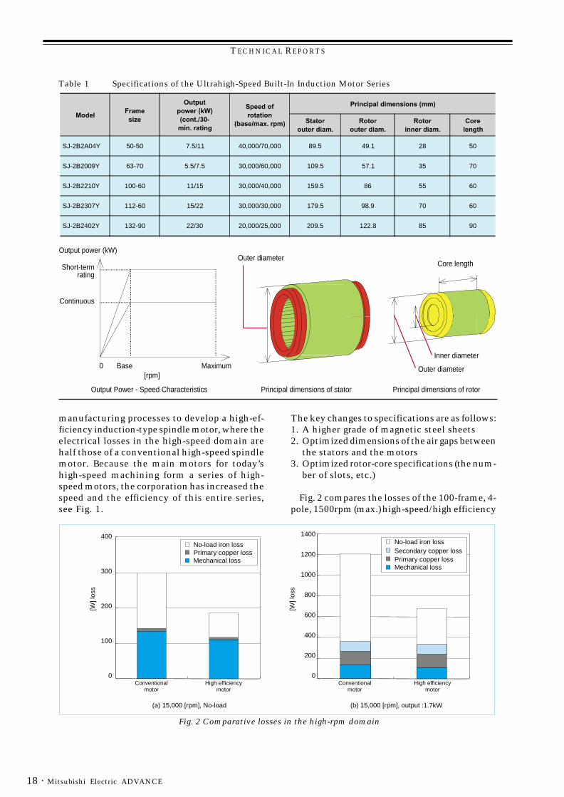
SJ-2B2A04Y 50-50 7.5/11 40,000/70,000 89.5 49.1 28 50
SJ-2B2009Y 63-70 5.5/7.5 30,000/60,000 109.5 57.1 35 70
SJ-2B2210Y 100-60 11/15 30,000/40,000 159.5 86 55 60
SJ-2B2307Y 112-60 15/22 30,000/30,000 179.5 98.9 70 60
SJ-2B2402Y 132-90 22/30 20,000/25,000 209.5 122.8 85 90
Output power (kW)
Short-termrating
Continuous
0 Base Maximum[rpm]
Output Power - Speed Characteristics
Outer diameter
Principal dimensions of stator Principal dimensions of rotor
Core length
Inner diameter
Outer diameter
Table 1 Specifications of the Ultrahigh-Speed Built-In Induction Motor Series[W
] los
s
400
200
300
100
0
No-load iron lossPrimary copper lossMechanical loss
[W] l
oss
400
600
800
200
0
No-load iron loss
Primary copper lossSecondary copper loss
Mechanical loss1000
1200
1400
Conventionalmotor
High efficiencymotor
Conventionalmotor
High efficiencymotor
(a) 15,000 [rpm], No-load
(b) 15,000 [rpm], output :1.7kW
Fig. 2 Comparative losses in the high-rpm domain
The key changes to specifications are as follows:1. A higher grade of magnetic steel sheets2. Optimized dimensions of the air gaps between
the stators and the motors3. Optimized rotor-core specifications (the num-
ber of slots, etc.)
Fig. 2 compares the losses of the 100-frame, 4-pole, 1500rpm (max.) high-speed/high efficiency
TECHNICAL REPORTS
· 19September 2003
CorePermanent magnet
Sleeve
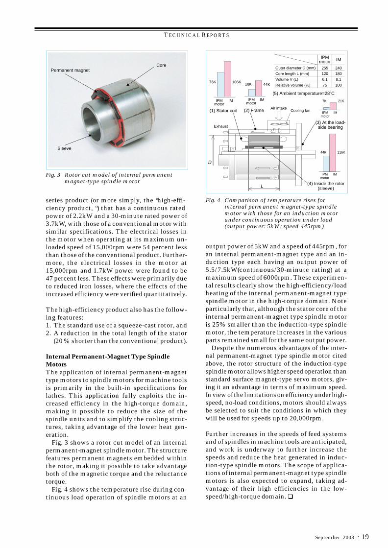
Fig. 3 Rotor cut model of internal permanentmagnet-type spindle motor
Fig. 4 Comparison of temperature rises forinternal permanent magnet-type spindlemotor with those for an induction motorunder continuous operation under load(output power: 5kW; speed 445rpm)
(1) Stator coil (2) Frame Air intakeCooling fan
(5) Ambient temperature=28oC
(3) At the load-side bearing
(4) Inside the rotor(sleeve)
Exhaust
IPMmotor IM
IPMmotor
IM
76K 106K
IPMmotor
IM
18K 44K
IPMmotor
IM
7K 21K
IPMmotor
IM
44K 116K
255 240Outer diameter D (mm)
120 180Core length L (mm)
6.1 8.1Volume V (L)
75 100Relative volume (%)
series product (or more simply, the “high-effi-ciency product, “) that has a continuous ratedpower of 2.2kW and a 30-minute rated power of3.7kW, with those of a conventional motor withsimilar specifications. The electrical losses inthe motor when operating at its maximum un-loaded speed of 15,000rpm were 54 percent lessthan those of the conventional product. Further-more, the electrical losses in the motor at15,000rpm and 1.7kW power were found to be47 percent less. These effects were primarily dueto reduced iron losses, where the effects of theincreased efficiency were verified quantitatively.
The high-efficiency product also has the follow-ing features:1. The standard use of a squeeze-cast rotor, and2. A reduction in the total length of the stator
(20 % shorter than the conventional product).
Internal Permanent-Magnet Type SpindleMotorsThe application of internal permanent-magnettype motors to spindle motors for machine toolsis primarily in the built-in specifications forlathes. This application fully exploits the in-creased efficiency in the high-torque domain,making it possible to reduce the size of thespindle units and to simplify the cooling struc-tures, taking advantage of the lower heat gen-eration.
Fig. 3 shows a rotor cut model of an internalpermanent-magnet spindle motor. The structurefeatures permanent magnets embedded withinthe rotor, making it possible to take advantageboth of the magnetic torque and the reluctancetorque.
Fig. 4 shows the temperature rise during con-tinuous load operation of spindle motors at an
output power of 5kW and a speed of 445rpm, foran internal permanent-magnet type and an in-duction type each having an output power of5.5/7.5kW(continuous/30-minute rating) at amaximum speed of 6000rpm. These experimen-tal results clearly show the high-efficiency/loadheating of the internal permanent-magnet typespindle motor in the high-torque domain. Noteparticularly that, although the stator core of theinternal permanent-magnet type spindle motoris 25% smaller than the induction-type spindlemotor, the temperature increases in the variousparts remained small for the same output power.
Despite the numerous advantages of the inter-nal permanent-magnet type spindle motor citedabove, the rotor structure of the induction-typespindle motor allows higher speed operation thanstandard surface magnet-type servo motors, giv-ing it an advantage in terms of maximum speed.In view of the limitations on efficiency under high-speed, no-load conditions, motors should alwaysbe selected to suit the conditions in which theywill be used for speeds up to 20,000rpm.
Further increases in the speeds of feed systemsand of spindles in machine tools are anticipated,and work is underway to further increase thespeeds and reduce the heat generated in induc-tion-type spindle motors. The scope of applica-tions of internal permanent-magnet type spindlemotors is also expected to expand, taking ad-vantage of their high efficiencies in the low-speed/high-torque domain. ❑
TECHNICAL HIGHLIGHTS
Mitsubishi Electric ADVANCE20 ·
*Haruyuki Kometani and Masaya Inoue are with the Advanced Technology R&D Center .
by Haruyuki Kometani and Masaya Inoue*
New Motor Electromagnetic DesignTechnologies
Field design has recently cometo play an essential role inachieving both improved perfor-mance and lower costs in elec-tromagnetic design for motors.It is therefore essential to estab-lish design methodologies thatuse previously unavailable com-puter capabilities in addition toconventionial design technolo-gies.
Design Technologies Relatingto Harmonics
BASIC THEORY OF HARMONICSIN MOTORS. Harmonics withinmotors can be divided into spa-tial harmonics and temporalharmonics, where physical phe-nomena can be inferred throughharmonic analyses of gap fluxdensity.[1]
The magnetic vibrationalforce F [N/m2] is expressed interms of the gap flux densityBg[T] by the following formula:
F = Bg2................................................ Eq.1
2µ0
Here, µ0 represents the perme-ability of free space. Thus, theorder of the space harmonics isgiven by the following formula:
2p
NsKs + NrKr + 6Kpsp + 4KBp + 0 −2p
........................ Eq.2
The order of the time harmon-ics is given by the following for-mula:
2p
NrKr(1 − s) + 4KB + 0 ................ Eq.3p −2p
TECHNICAL HIGHLIGHTS
and so on, in that order, whereNs is the stator slot number, Nr
is the rotor slot number, s theslip factor, p the pole pair andKs, Kr, Kps and KB are arbitraryintegers.
Here the first term is the sta-tor-slot harmonics, the secondterm is the rotor-slot harmonics,the third term is the stator mag-netic motive-force harmonics,and the fourth term is the har-monics from magnetic satura-tion.
This theoretical treatmentcan be extended to optimizephysical shapes in permanent-magnet motors so as to reducetorque ripple, and to optimizethe slot combinations in induc-tion motors.
ELECTROMAGNETIC VIBRATIONAL-FORCE ANALYSIS IN SMALL INDUC-TION MOTORS. Quantificationusing electromagnetic fieldanalysis is required when inves-
tigating the size of the harmon-ics. In this section, we will ana-lyze the changes in the electro-magnetic vibrational force re-sulting from skew in small in-duction motors as an effect ofthe harmonics. The analyticalmodel uses the three-phase in-duction motor model K of the In-stitute of Electrical Engineers ofJapan found in Reference[2].
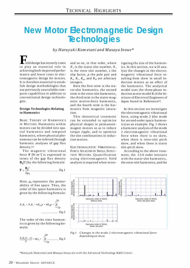
In this section we investigatethe electromagnetic vibrationalforce, using mode 2 (the modefor second-order space harmon-ics) as an example. Fig. 1 showsa harmonic analysis of the mode2 electromagnetic vibrationalforce when there is no skew,when there is rotor-slot pitchskew, and when there is statorslot-pitch skew.
According to the above treat-ment, the -13.6 order interactswith the stator-slot harmonics ,the rotor-slot harmonics, and the
Fig 1 Changes in the mode 2 electromagnetic vibrational forcedepending on skew
Ele
ctro
mag
netic
vibr
atio
nal f
orce
(%
)E
lect
rom
agne
ticvi
brat
iona
l for
ce (
%)
Ele
ctro
mag
netic
vibr
atio
nal f
orce
(%
)
Harmonic order (X 50Hz)Without skew
Harmonic order (X 50Hz)Stator slot pitch
Harmonic order (X 50Hz)Rotor slot pitch skew
TECHNICAL HIGHLIGHTS
· 21September 2003
5th and 7th stator magneticmotive-force harmonics. The15.6 order has a primary inter-action with the stator-slot har-monics, the rotor-slot harmo-nics, and the 5th stator mag-netic motive-force harmonics.This figure shows that the elec-tromagnetic vibrational forcescan be reduced substanitally byskew.
Design Technologies for IronLoss and Stray Loss
METHODS OF INVESTIGATINGIRON LOSS AND STRAY LOSS.The magnetic flux density in theiron core can be calculated us-ing the finite-element method,making it possible to calculatethe iron loss. If the maximumvalue for the magnetic-flux den-sity for each element is definedas |Bm| [T] and the maximumvalue for the n-order harmoniccomponent in the magneticflux-density frequency analysisresults is expressed as B(n) [T],then the hysteresis loss Wh [W]and the eddy-current loss We [W]can be expressed by the follow-ing formulae:
Wh = ∑ ∑ [Kf Kh |Bm|xf DV]
ne ax
.......... Eq.4
Wh = ∑ ∑ ∑[Kc Kh By(n)(nf)z DV]
ne ax n
......... Eq.5
Here, f represents the base fre-quency (Hz), D the density (kg/m3), V the volume of the ele-ment (m3), Kf the hysteresis-lossmultiplier due to residual stress.Kc the eddy-current loss multi-plier[3] due to overlapping har-monics or the surface-loss multi-plier, ax is the radial directionand the tangential direction, andne the number of elements in thecore. Here Kh, x, Ke, y and z arecalculated from the iron-losscurves derived experimentallyfrom the materials.
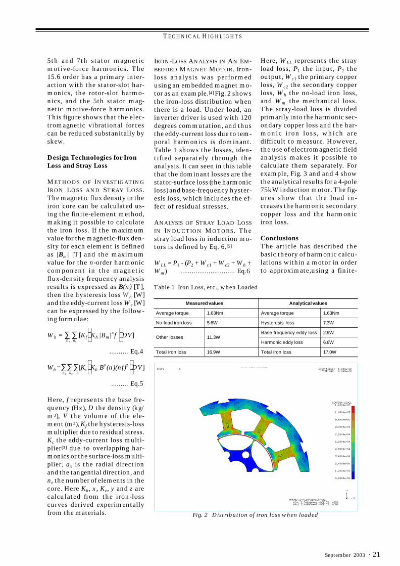
IRON-LOSS ANALYSIS IN AN EM-BEDDED MAGNET MOTOR. Iron-loss analysis was performedusing an embedded magnet mo-tor as an example.[4] Fig. 2 showsthe iron-loss distribution whenthere is a load. Under load, aninverter driver is used with 120degrees commutation, and thusthe eddy-current loss due to tem-poral harmonics is dominant.Table 1 shows the losses, iden-tified separately through theanalysis. It can seen in this tablethat the dominant losses are thestator-surface loss (the harmonicloss) and base-frequency hyster-esis loss, which includes the ef-fect of residual stresses.
ANALYSIS OF STRAY LOAD LOSSIN INDUCTION MOTORS. Thestray load loss in induction mo-tors is defined by Eq. 6.[5]
WLL = P1 - (P2 + Wc1 + Wc2 + Wh +Wm) ............................. Eq.6
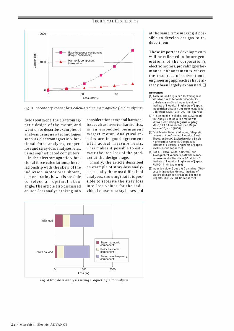
Here, WLL represents the strayload loss, P1 the input, P2 theoutput, Wc1 the primary copperloss, Wc2 the secondary copperloss, Wh the no-load iron loss,and Wm the mechanical loss.The stray-load loss is dividedprimarily into the harmonic sec-ondary copper loss and the har-monic iron loss, which aredifficult to measure. However,the use of electromagnetic fieldanalysis makes it possible tocalculate them separately. Forexample, Fig. 3 and and 4 showthe analytical results for a 4-pole75kW induction motor. The fig-ures show that the load in-creases the harmonic secondarycopper loss and the harmoniciron loss.
ConclusionsThe article has described thebasic theory of harmonic calcu-lations within a motor in orderto approximate,using a finite-
Table 1 Iron Loss, etc., when Loaded
Measured values Analytical values
Average torque 1.63Nm Average torque 1.63Nm
No-load iron loss 5.6W Hysteresis loss 7.3W
Other losses 11.3WBase frequency eddy loss 2.9W
Harmonic eddy loss 6.6W
Total iron loss 16.9W Total iron loss 17.0W
Fig. 2 Distribution of iron loss when loaded
TECHNICAL HIGHLIGHTS
Mitsubishi Electric ADVANCE22 ·
field treatment, the electromag-netic design of the motor, andwent on to describe examples ofanalysis using new technologiessuch as electromagnetic vibra-tional force analyses, copper-loss and stray-loss analyses, etc.,using sophisticated computers.
In the electromagnetic vibra-tional force calculations,the re-lationship with the skew of theinduction motor was shown,demonstrating how it is possibleto select an optimal skewangle.The article also discussedan iron-loss analysis taking into
consideration temporal harmon-ics, such as inverter harmonics,in an embedded permanentmagnet motor. Analytical re-sults are in good agreementwith actual measurements.This makes it possible to esti-mate the iron loss of the prod-uct at the design stage.
Finally, the article describedan example of stray-loss analy-sis, usually the most difficult ofanalyses, showing that it is pos-sible to separate the stray lossinto loss values for the indi-vidual causes of stray losses and
at the same time making it pos-sible to develop designs to re-duce them.
These important developmentswill be reflected in future gen-erations of the corporation’selectric motors, providing perfor-mance enhancements wherethe resources of conventionalengineering approaches have al-ready been largely exhausted. ❑
References[1]Kometani and Deguchi; “Electromagnetic
Vibration due to Secondary ConductorUnbalance in a Small Induction Motor,”Institute of Electrical Engineers of Japan,Industrial Application Department, NationalConference, No. 104 (1997) (in Japanese)
[2]H. Kometani, S. Sakabe, and A. Kameari;“3D Analysis of Induction Motor withSkewed Slots Using Regular CouplingMesh,” IEEE Transactions on Magn.,Volume 36, No.4 (2000)
[3]Tani, Morita, Naka, and Inoue; “MagneticLosses of Non-Oriented Electrical SteelSheets under AC Excitation with a SingleHigher Order Harmonic Component,”Institute of Electrical Engineers of Japan,RM 00-302 (in Japanese)
[4]Baba, Oikawa, Akita, Kometani, andKawaguchi: “Examination of PerformanceImprovement in Brushless DC Motors,”Institute of Electrical Engineers of Japan,RM 00-141 (in Japanese)
[5] Induction Motor Specialty Commitee: “StrayLoss in Induction Motors,” Institute ofElectrical Engineers of Japan, TechnicalReports, 58 (1963-8) (in Japanese)
Fig. 3 Secondary copper loss calculated using magnetic field analysuis
Fig. 4 Iron-loss analysis using magnetic field analysis
With load
With no-load
0 1000 2000Loss (W)
Stator harmoniccomponent
Rotor harmoniccomponent
Stator base frequencycomponent
100500
1000
0
2000
Loss rate(%)
Cop
per
loss
Base frequency component(torque component)
Harmonic component(stray loss)
TECHNICAL HIGHLIGHTS
· 23September 2003
*Nobuaki Miyake is with the Manufacturing Engineering Center.
by Nobuaki Miyake*
New Motor ManufacturingTechnologies
C onventional technologiesare reaching the limits of whatcan be achieved in reducing en-ergy consumption and increas-ing efficiency. This makes“design for manufacturing,”which reexamines the basicstructural and electromagneticdesigns from the point of viewof ease in manufacturing, criti-cally important. MitsubishiElectric Corporation has re-viewed the basic structures ofits motors, focusing on core-assembly and coil-winding tech-nology, developing the so-called“Poki-poki Motor” since 1993,and so responding to a broad va-riety of product requirements.
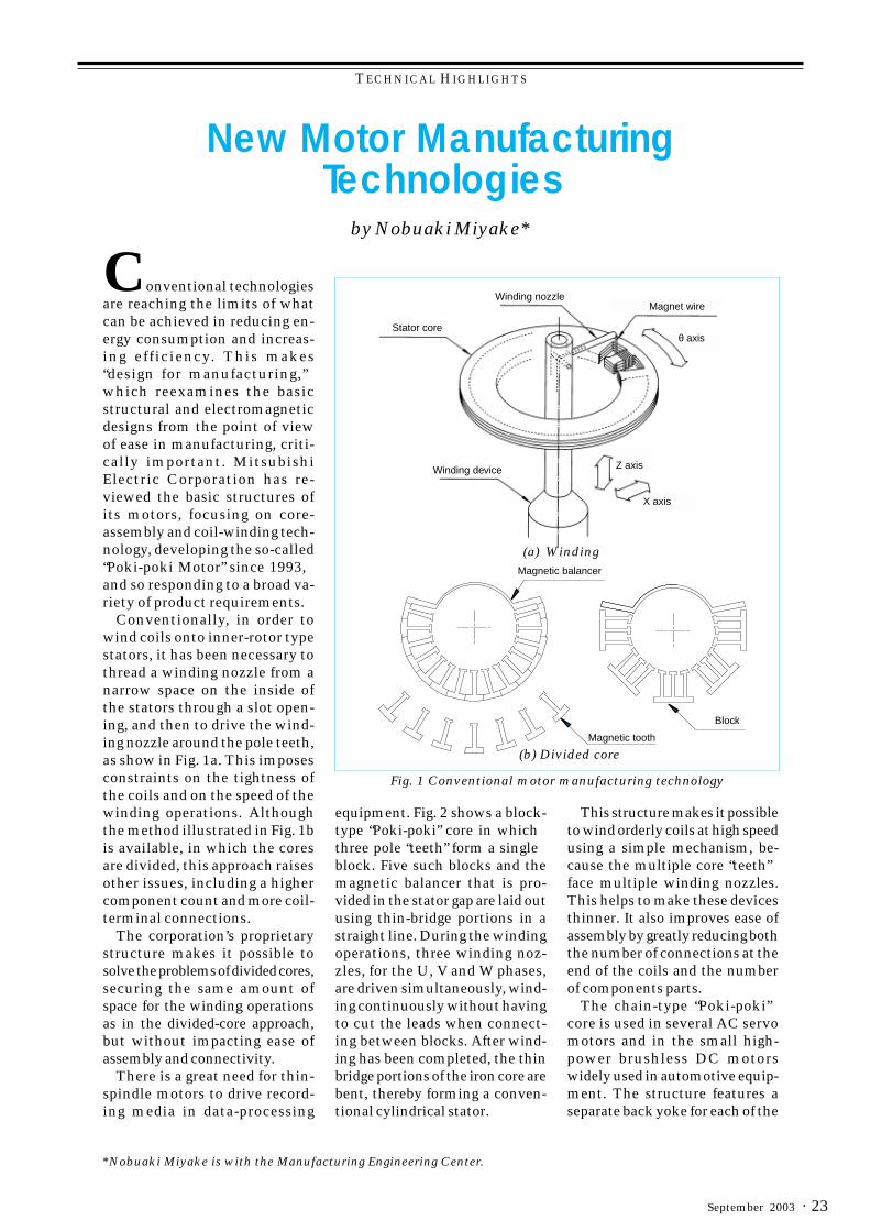
Conventionally, in order towind coils onto inner-rotor typestators, it has been necessary tothread a winding nozzle from anarrow space on the inside ofthe stators through a slot open-ing, and then to drive the wind-ing nozzle around the pole teeth,as show in Fig. 1a. This imposesconstraints on the tightness ofthe coils and on the speed of thewinding operations. Althoughthe method illustrated in Fig. 1bis available, in which the coresare divided, this approach raisesother issues, including a highercomponent count and more coil-terminal connections.
The corporation’s proprietarystructure makes it possible tosolve the problems of divided cores,securing the same amount ofspace for the winding operationsas in the divided-core approach,but without impacting ease ofassembly and connectivity.
There is a great need for thin-spindle motors to drive record-ing media in data-processing
Stator core
Winding nozzleMagnet wire
θ axis
Z axis
X axis
Winding device
Magnetic balancer
Magnetic tooth
Block
(a) Winding
(b) Divided core
Fig. 1 Conventional motor manufacturing technology
equipment. Fig. 2 shows a block-type “Poki-poki” core in whichthree pole “teeth” form a singleblock. Five such blocks and themagnetic balancer that is pro-vided in the stator gap are laid outusing thin-bridge portions in astraight line. During the windingoperations, three winding noz-zles, for the U, V and W phases,are driven simultaneously, wind-ing continuously without havingto cut the leads when connect-ing between blocks. After wind-ing has been completed, the thinbridge portions of the iron core arebent, thereby forming a conven-tional cylindrical stator.
This structure makes it possibleto wind orderly coils at high speedusing a simple mechanism, be-cause the multiple core “teeth”face multiple winding nozzles.This helps to make these devicesthinner. It also improves ease ofassembly by greatly reducing boththe number of connections at theend of the coils and the numberof components parts.
The chain-type “Poki-poki”core is used in several AC servomotors and in the small high-power brushless DC motorswidely used in automotive equip-ment. The structure features aseparate back yoke for each of the
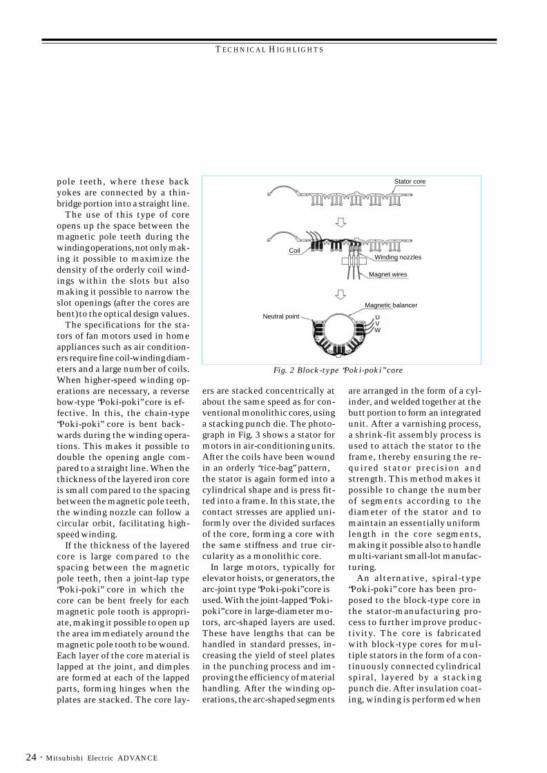
TECHNICAL HIGHLIGHTS
Mitsubishi Electric ADVANCE24 ·
pole teeth, where these backyokes are connected by a thin-bridge portion into a straight line.
The use of this type of coreopens up the space between themagnetic pole teeth during thewinding operations, not only mak-ing it possible to maximize thedensity of the orderly coil wind-ings within the slots but alsomaking it possible to narrow theslot openings (after the cores arebent) to the optical design values.
The specifications for the sta-tors of fan motors used in homeappliances such as air condition-ers require fine coil-winding diam-eters and a large number of coils.When higher-speed winding op-erations are necessary, a reversebow-type “Poki-poki” core is ef-fective. In this, the chain-type“Poki-poki” core is bent back-wards during the winding opera-tions. This makes it possible todouble the opening angle com-pared to a straight line. When thethickness of the layered iron coreis small compared to the spacingbetween the magnetic pole teeth,the winding nozzle can follow acircular orbit, facilitating high-speed winding.
If the thickness of the layeredcore is large compared to thespacing between the magneticpole teeth, then a joint-lap type“Poki-poki” core in which thecore can be bent freely for eachmagnetic pole tooth is appropri-ate, making it possible to open upthe area immediately around themagnetic pole tooth to be wound.Each layer of the core material islapped at the joint, and dimplesare formed at each of the lappedparts, forming hinges when theplates are stacked. The core lay-
ers are stacked concentrically atabout the same speed as for con-ventional monolithic cores, usinga stacking punch die. The photo-graph in Fig. 3 shows a stator formotors in air-conditioning units.After the coils have been woundin an orderly “rice-bag” pattern,the stator is again formed into acylindrical shape and is press fit-ted into a frame. In this state, thecontact stresses are applied uni-formly over the divided surfacesof the core, forming a core withthe same stiffness and true cir-cularity as a monolithic core.
In large motors, typically forelevator hoists, or generators, thearc-joint type “Poki-poki” core isused. With the joint-lapped “Poki-poki” core in large-diameter mo-tors, arc-shaped layers are used.These have lengths that can behandled in standard presses, in-creasing the yield of steel platesin the punching process and im-proving the efficiency of materialhandling. After the winding op-erations, the arc-shaped segments
are arranged in the form of a cyl-inder, and welded together at thebutt portion to form an integratedunit. After a varnishing process,a shrink-fit assembly process isused to attach the stator to theframe, thereby ensuring the re-quired stator precision andstrength. This method makes itpossible to change the numberof segments according to thediameter of the stator and tomaintain an essentially uniformlength in the core segments,making it possible also to handlemulti-variant small-lot manufac-turing.
An alternative, spiral-type“Poki-poki” core has been pro-posed to the block-type core inthe stator-manufacturing pro-cess to further improve produc-tivity. The core is fabricatedwith block-type cores for mul-tiple stators in the form of a con-tinuously connected cylindricalspiral, layered by a stackingpunch die. After insulation coat-ing, winding is performed when
Fig. 2 Block-type “Poki-poki” core
Stator core
U V W
CoilWinding nozzles
Magnetic balancer
Magnet wires
Neutral point
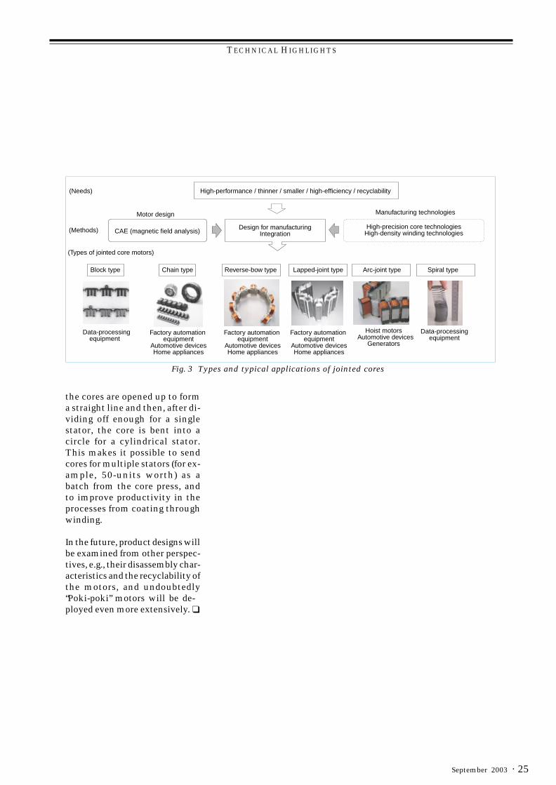
TECHNICAL HIGHLIGHTS
· 25September 2003
the cores are opened up to forma straight line and then, after di-viding off enough for a singlestator, the core is bent into acircle for a cylindrical stator.This makes it possible to sendcores for multiple stators (for ex-ample, 50-units worth) as abatch from the core press, andto improve productivity in theprocesses from coating throughwinding.
In the future, product designs willbe examined from other perspec-tives, e.g., their disassembly char-acteristics and the recyclability ofthe motors, and undoubtedly“Poki-poki” motors will be de-ployed even more extensively. ❑
Fig. 3 Types and typical applications of jointed cores
High-performance / thinner / smaller / high-efficiency / recyclability(Needs)
(Methods)
Motor design
CAE (magnetic field analysis)
Manufacturing technologies
High-precision core technologiesHigh-density winding technologies
Design for manufacturingIntegration
(Types of jointed core motors)
Block type Chain type Reverse-bow type Lapped-joint type Arc-joint type Spiral type
Data-processingequipment
Factory automation equipment
Automotive devicesHome appliances
Factory automation equipment
Automotive devicesHome appliances
Factory automation equipment
Automotive devicesHome appliances
Hoist motors Automotive devices
Generators
Data-processingequipment
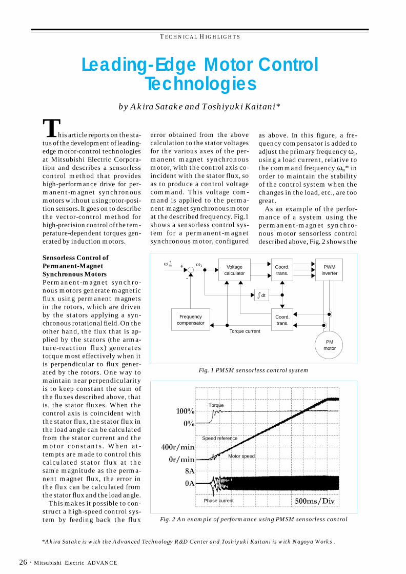
TECHNICAL HIGHLIGHTS
Mitsubishi Electric ADVANCE26 ·
*Akira Satake is with the Advanced Technology R&D Center and Toshiyuki Kaitani is with Nagoya Works .
by Akira Satake and Toshiyuki Kaitani*
Leading-Edge Motor ControlTechnologies
This article reports on the sta-tus of the development of leading-edge motor-control technologiesat Mitsubishi Electric Corpora-tion and describes a sensorlesscontrol method that provideshigh-performance drive for per-manent-magnet synchronousmotors without using rotor-posi-tion sensors. It goes on to describethe vector-control method forhigh-precision control of the tem-perature-dependent torques gen-erated by induction motors.
Sensorless Control ofPermanent-MagnetSynchronous MotorsPermanent-magnet synchro-nous motors generate magneticflux using permanent magnetsin the rotors, which are drivenby the stators applying a syn-chronous rotational field. On theother hand, the flux that is ap-plied by the stators (the arma-ture-reaction flux) generatestorque most effectively when itis perpendicular to flux gener-ated by the rotors. One way tomaintain near perpendicularityis to keep constant the sum ofthe fluxes described above, thatis, the stator fluxes. When thecontrol axis is coincident withthe stator flux, the stator flux inthe load angle can be calculatedfrom the stator current and themotor constants. When at-tempts are made to control thiscalculated stator flux at thesame magnitude as the perma-nent magnet flux, the error inthe flux can be calculated fromthe stator flux and the load angle.
This makes it possible to con-struct a high-speed control sys-tem by feeding back the flux
error obtained from the abovecalculation to the stator voltagesfor the various axes of the per-manent magnet synchronousmotor, with the control axis co-incident with the stator flux, soas to produce a control voltagecommand. This voltage com-mand is applied to the perma-nent-magnet synchronous motorat the described frequency. Fig.1shows a sensorless control sys-tem for a permanent-magnetsynchronous motor, configured
as above. In this figure, a fre-quency compensator is added toadjust the primary frequency ω1,using a load current, relative tothe command frequency ωm* inorder to maintain the stabilityof the control system when thechanges in the load, etc., are toogreat.
As an example of the perfor-mance of a system using thepermanent-magnet synchro-nous motor sensorless controldescribed above, Fig. 2 shows the
Fig. 2 An example of performance using PMSM sensorless control
Torque
Speed reference
Motor speed
Phase current
Fig. 1 PMSM sensorless control system
PWMinverter
Coord.trans.
Coord.trans.
dt
Frequencycompensator
Voltagecalculator
Torque current
1m +
-
PMmotor
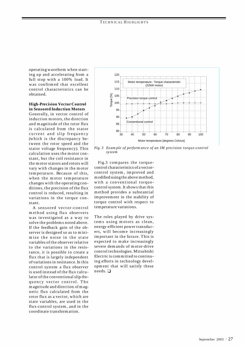
TECHNICAL HIGHLIGHTS
· 27September 2003
operating waveform when start-ing up and accelerating from afull stop with a 100% load. Itwas confirmed that excellentcontrol characteristics can beobtained.
High-Precision Vector Controlin Sensored Induction MotorsGenerally, in vector control ofinduction motors, the directionand magnitude of the rotor fluxis calculated from the statorcurrent and slip frequency(which is the discrepancy be-tween the rotor speed and thestator voltage frequency). Thiscalculation uses the motor con-stant, but the coil resistance inthe motor stators and rotors willvary with changes in the motortemperature. Because of this,when the motor temperaturechanges with the operating con-ditions, the precision of the fluxcontrol is reduced, resulting invariations in the torque con-stant.
A sensored vector-controlmethod using flux observerswas investigated as a way tosolve the problems noted above.If the feedback gain of the ob-server is designed so as to mini-mize the noise in the statevariables of the observer relativeto the variations in the resis-tance, it is possible to create aflux that is largely independentof variations in resistance. In thiscontrol system a flux observeris used instead of the flux calcu-lator of the conventional slip-fre-quency vector control. Themagnitude and direction of mag-netic flux calculated from therotor flux as a vector, which arestate variables, are used in theflux-control system, and in thecoordinate transformation.
Fig.3 compares the torque-control characteristics of a vector-control system, improved andmodified using the above method,with a conventional torque-control system. It shows that thismethod provides a substantialimprovement in the stability oftorque control with respect totemperature variations.
The roles played by drive sys-tems using motors as clean,energy-efficient power transduc-ers, will become increasinglyimportant in the future. This isexpected to make increasinglysevere demands of motor-drivecontrol technologies. MitsubishiElectric is committed to continu-ing efforts in technology devel-opment that will satisfy theseneeds. ❑
Fig. 3 Example of performance of an IM precision torque-controlsystem
Motor temperature [degrees Celcius]
Torq
ue [%
]
30
120
115
110
105
100
95
90
85
8040 50 60 70 80 90 100
Precision torque control
Conventional control
Motor temperature - Torque characteristic(22kW motor)
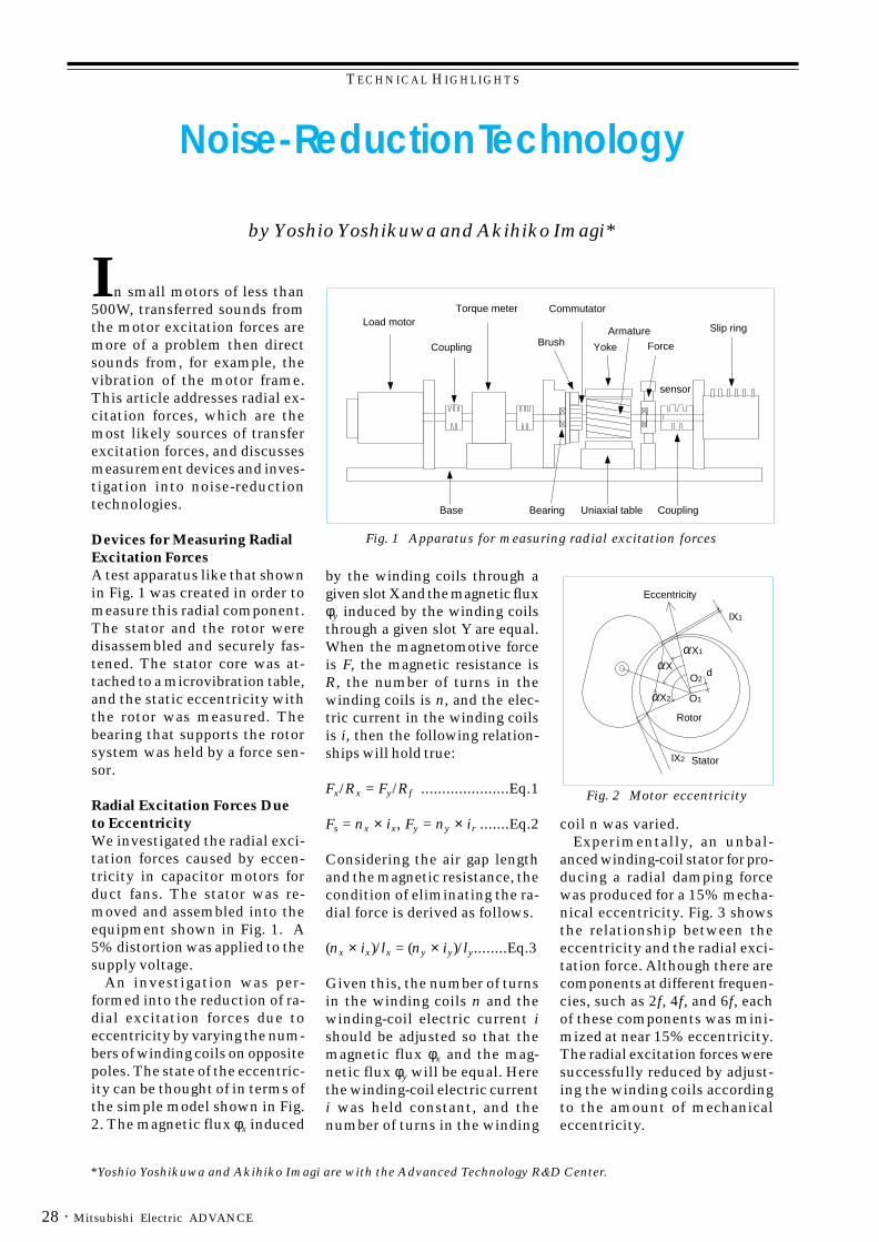
TECHNICAL HIGHLIGHTS
Mitsubishi Electric ADVANCE28 ·
*Yoshio Yoshikuwa and Akihiko Imagi are with the Advanced Technology R&D Center.
by Yoshio Yoshikuwa and Akihiko Imagi*
Noise-Reduction Technology
In small motors of less than500W, transferred sounds fromthe motor excitation forces aremore of a problem then directsounds from, for example, thevibration of the motor frame.This article addresses radial ex-citation forces, which are themost likely sources of transferexcitation forces, and discussesmeasurement devices and inves-tigation into noise-reductiontechnologies.
Devices for Measuring RadialExcitation ForcesA test apparatus like that shownin Fig. 1 was created in order tomeasure this radial component.The stator and the rotor weredisassembled and securely fas-tened. The stator core was at-tached to a microvibration table,and the static eccentricity withthe rotor was measured. Thebearing that supports the rotorsystem was held by a force sen-sor.
Radial Excitation Forces Dueto EccentricityWe investigated the radial exci-tation forces caused by eccen-tricity in capacitor motors forduct fans. The stator was re-moved and assembled into theequipment shown in Fig. 1. A5% distortion was applied to thesupply voltage.
An investigation was per-formed into the reduction of ra-dial excitation forces due toeccentricity by varying the num-bers of winding coils on oppositepoles. The state of the eccentric-ity can be thought of in terms ofthe simple model shown in Fig.2. The magnetic flux φx induced
by the winding coils through agiven slot X and the magnetic fluxφy induced by the winding coilsthrough a given slot Y are equal.When the magnetomotive forceis F, the magnetic resistance isR, the number of turns in thewinding coils is n, and the elec-tric current in the winding coilsis i, then the following relation-ships will hold true:
Fx/Rx = Fy/Rf .....................Eq.1
Fs = nx × ix, Fy = ny × ir .......Eq.2
Considering the air gap lengthand the magnetic resistance, thecondition of eliminating the ra-dial force is derived as follows.
(nx × ix)/lx = (ny × iy)/ly........Eq.3
Given this, the number of turnsin the winding coils n and thewinding-coil electric current ishould be adjusted so that themagnetic flux φx and the mag-netic flux φy will be equal. Herethe winding-coil electric currenti was held constant, and thenumber of turns in the winding
Fig. 1 Apparatus for measuring radial excitation forces
Fig. 2 Motor eccentricity
coil n was varied.Experimentally, an unbal-
anced winding-coil stator for pro-ducing a radial damping forcewas produced for a 15% mecha-nical eccentricity. Fig. 3 showsthe relationship between theeccentricity and the radial exci-tation force. Although there arecomponents at different frequen-cies, such as 2f, 4f, and 6f, eachof these components was mini-mized at near 15% eccentricity.The radial excitation forces weresuccessfully reduced by adjust-ing the winding coils accordingto the amount of mechanicaleccentricity.
Slip ring
YokeBrush
Torque meterLoad motor
Coupling Force
sensor
Uniaxial tableBase
Armature
Commutator
CouplingBearing
Eccentricity
StatorlX2
Rotor
O2
O1
d
X1
lX1
X
X2
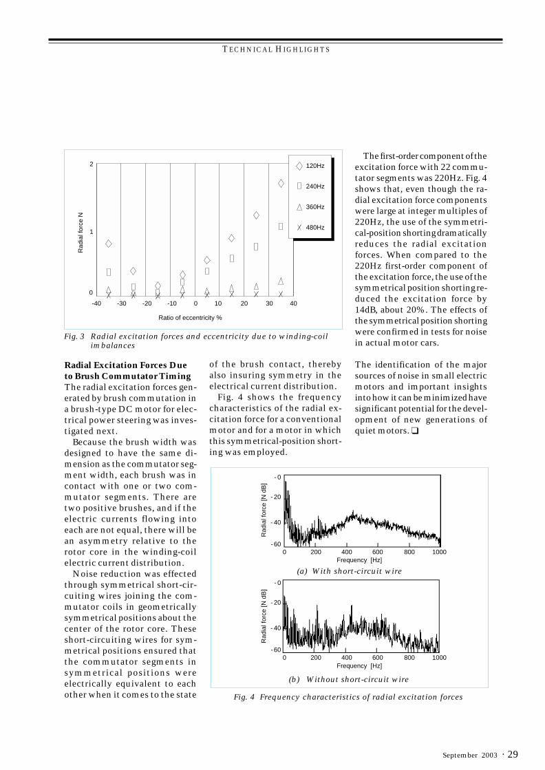
TECHNICAL HIGHLIGHTS
· 29September 2003
Radial Excitation Forces Dueto Brush Commutator TimingThe radial excitation forces gen-erated by brush commutation ina brush-type DC motor for elec-trical power steering was inves-tigated next.
Because the brush width wasdesigned to have the same di-mension as the commutator seg-ment width, each brush was incontact with one or two com-mutator segments. There aretwo positive brushes, and if theelectric currents flowing intoeach are not equal, there will bean asymmetry relative to therotor core in the winding-coilelectric current distribution.
Noise reduction was effectedthrough symmetrical short-cir-cuiting wires joining the com-mutator coils in geometricallysymmetrical positions about thecenter of the rotor core. Theseshort-circuiting wires for sym-metrical positions ensured thatthe commutator segments insymmetrical positions wereelectrically equivalent to eachother when it comes to the state
of the brush contact, therebyalso insuring symmetry in theelectrical current distribution.
Fig. 4 shows the frequencycharacteristics of the radial ex-citation force for a conventionalmotor and for a motor in whichthis symmetrical-position short-ing was employed.
Fig. 3 Radial excitation forces and eccentricity due to winding-coilimbalances
The first-order component of theexcitation force with 22 commu-tator segments was 220Hz. Fig. 4shows that, even though the ra-dial excitation force componentswere large at integer multiples of220Hz, the use of the symmetri-cal-position shorting dramaticallyreduces the radial excitationforces. When compared to the220Hz first-order component ofthe excitation force, the use of thesymmetrical position shorting re-duced the excitation force by14dB, about 20%. The effects ofthe symmetrical position shortingwere confirmed in tests for noisein actual motor cars.
The identification of the majorsources of noise in small electricmotors and important insightsinto how it can be minimized havesignificant potential for the devel-opment of new generations ofquiet motors. ❑
Fig. 4 Frequency characteristics of radial excitation forces
Rad
ial f
orce
N
Ratio of eccentricity %
240Hz
120Hz
360Hz
480Hz
2
1
0
-40 40-30 30-20 20-10 100
Rad
ial f
orce
[N d
B]
R
adia
l for
ce [N
dB
]
- 60
- 40
- 20
- 0
0 200 400 600 800 1000
- 60
- 40
- 20
- 0
0 200 400 600 800 1000Frequency [Hz]
Frequency [Hz]
(a) With short-circuit wire
(b) Without short-circuit wire
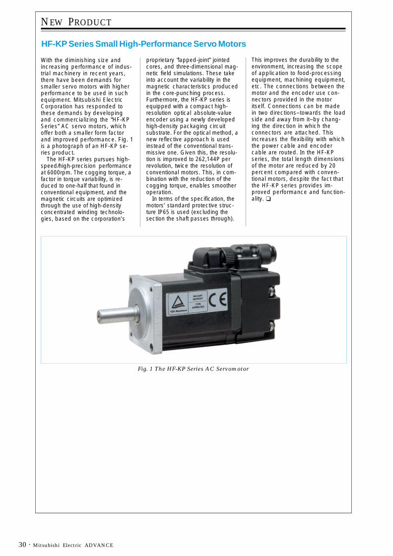
Mitsubishi Electric ADVANCE30 ·
NEW PRODUCT
HF-KP Series Small High-Performance Servo Motors
With the diminishing size andincreasing performance of indus-trial machinery in recent years,there have been demands forsmaller servo motors with higherperformance to be used in suchequipment. Mitsubishi ElectricCorporation has responded tothese demands by developingand commercializing the “HF-KPSeries” AC servo motors, whichoffer both a smaller form factorand improved performance. Fig. 1is a photograph of an HF-KP se-ries product.
The HF-KP series pursues high-speed/high-precision performanceat 6000rpm. The cogging torque, afactor in torque variability, is re-duced to one-half that found inconventional equipment, and themagnetic circuits are optimizedthrough the use of high-densityconcentrated winding technolo-gies, based on the corporation’s
proprietary “lapped-joint” jointedcores, and three-dimensional mag-netic field simulations. These takeinto account the variability in themagnetic characteristics producedin the core-punching process.Furthermore, the HF-KP series isequipped with a compact high-resolution optical absolute-valueencoder using a newly developedhigh-density packaging circuitsubstrate. For the optical method, anew reflective approach is usedinstead of the conventional trans-missive one. Given this, the resolu-tion is improved to 262,144P perrevolution, twice the resolution ofconventional motors. This, in com-bination with the reduction of thecogging torque, enables smootheroperation.
In terms of the specification, themotors’ standard protective struc-ture IP65 is used (excluding thesection the shaft passes through).
This improves the durability to theenvironment, increasing the scopeof application to food-processingequipment, machining equipment,etc. The connections between themotor and the encoder use con-nectors provided in the motoritself. Connections can be madein two directions--towards the loadside and away from it--by chang-ing the direction in which theconnectors are attached. Thisincreases the flexibility with whichthe power cable and encodercable are routed. In the HF-KPseries, the total length dimensionsof the motor are reduced by 20percent compared with conven-tional motors, despite the fact thatthe HF-KP series provides im-proved performance and function-ality. ❑
Fig. 1 The HF-KP Series AC Servomotor


![Gearless-Drives - Modern Lift Tech · Diameter of Traction Sheave DT [mm] 240 Diameter of Ropes ... With our gearless machine we can offer the respectively matched frequency ... precisely](https://img.pdfslide.us/doc/110x75/5b2a43057f8b9aa3308b4941/gearless-drives-modern-lift-diameter-of-traction-sheave-dt-mm-240-diameter.jpg)