Embed Size (px)
Citation preview
*1601-9034-A7*
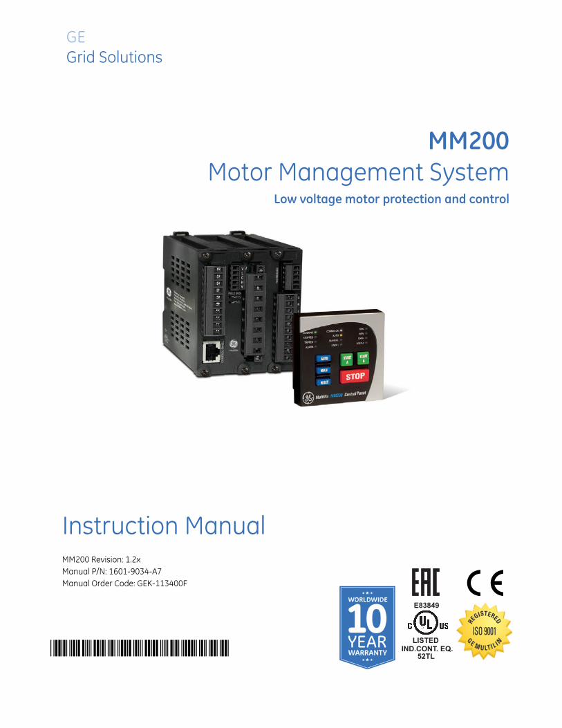
MM200Motor Management System
Low voltage motor protection and control
GEGrid Solutions
LISTED
52TL
IND.CONT. EQ.
E83849
Instruction ManualMM200 Revision: 1.2xManual P/N: 1601-9034-A7Manual Order Code: GEK-113400F
© 2015 GE Multilin Incorporated. All rights reserved.
GE Multilin MM200 Motor Management System instruction manual for revision 1.2x.
MM200 Motor Management System, EnerVista, EnerVista Launchpad, and EnerVista MM300/MM200 Setup are registered trademarks of GE Multilin Inc.
The contents of this manual are the property of GE Multilin Inc. This documentation is furnished on license and may not be reproduced in whole or in part without the permission of GE Multilin. The content of this manual is for informational use only and is subject to change without notice.
Part number: 1601-9034-A7 (December 2015)
StorageStore the unit indoors in a cool, dry place. If possible, store in the original packaging. Follow the storage temperature range outlined in the Specifications.
To avoid deterioration of electrolytic capacitors, power up units that are stored in a de-energized state once per year, for one hour continuously.
This product cannot be disposed of as unsorted municipal waste in the European Union. For proper recycling return this product to your supplier or a designated collection point. For more information go to www.recyclethis.info.
MM200 MOTOR MANAGEMENT SYSTEM – INSTRUCTION MANUAL TOC–I
Table of Contents
1.INTRODUCTION Overview .............................................................................................................................................. 1 - 1Cautions and Warnings..........................................................................................................................1 - 2For Further Assistance ............................................................................................................................1 - 3Description of the MM200 Motor Management system .........................................................1 - 4MM200 order codes .................................................................................................................................1 - 5Example of an MM200 order code....................................................................................................1 - 5
Specifications..................................................................................................................................... 1 - 6Protection specifications .......................................................................................................................1 - 6User interface specifications ...............................................................................................................1 - 7Control specifications..............................................................................................................................1 - 7Inputs specifications ................................................................................................................................1 - 8Outputs specifications ............................................................................................................................1 - 8Power supply specifications.................................................................................................................1 - 9Communications specifications .........................................................................................................1 - 9Testing and certification ........................................................................................................................1 - 9Physical specifications......................................................................................................................... 1 - 10Environmental specifications ........................................................................................................... 1 - 11
2.INSTALLATION Mechanical installation ................................................................................................................. 2 - 1Dimensions...................................................................................................................................................2 - 1Product identification ..............................................................................................................................2 - 2Mounting .......................................................................................................................................................2 - 3
Electrical installation ...................................................................................................................... 2 - 4Thermistor connections .........................................................................................................................2 - 8RS485 connections ...................................................................................................................................2 - 9Protection................................................................................................................................................... 2 - 10Input/output.............................................................................................................................................. 2 - 13Dielectric strength testing.................................................................................................................. 2 - 14
Starter types .....................................................................................................................................2 - 15Full-voltage non-reversing starter ................................................................................................. 2 - 15Full-voltage reversing starter ........................................................................................................... 2 - 17Two-speed starter.................................................................................................................................. 2 - 18
General Maintenance...................................................................................................................2 - 20In-service maintenance ...................................................................................................................... 2 - 20Out-of-service maintenance............................................................................................................. 2 - 20Unscheduled maintenance (system interruption)................................................................... 2 - 20
3.CONTROL PANEL Basic control panel.......................................................................................................................... 3 - 2MM200 graphical display page hierarchy............................................................................ 3 - 3EnerVista MM200 Setup Software............................................................................................ 3 - 4
Software requirements...........................................................................................................................3 - 4Installing the EnerVista MM200 Setup software.........................................................................3 - 4Backing up settings..................................................................................................................................3 - 6Restoring settings .....................................................................................................................................3 - 6Upgrading firmware.................................................................................................................................3 - 7Upgrading the software.........................................................................................................................3 - 8Uninstalling files and clearing data ..................................................................................................3 - 8
4.SETPOINTS Understanding setpoints.............................................................................................................. 4 - 1

TOC–II MM200 MOTOR MANAGEMENT SYSTEM – INSTRUCTION MANUAL
Setting text abbreviations..................................................................................................................... 4 - 1Configuration setpoints .................................................................................................................4 - 2
Motor setpoints.......................................................................................................................................... 4 - 2Current transformers .............................................................................................................................. 4 - 6Inputs.............................................................................................................................................................. 4 - 7Outputs .......................................................................................................................................................... 4 - 8Communications setpoints .................................................................................................................. 4 - 8System............................................................................................................................................................ 4 - 9
Protection elements ..................................................................................................................... 4 - 12Thermal protection.................................................................................................................................4 - 12Mechanical protection..........................................................................................................................4 - 17Electrical protection...............................................................................................................................4 - 19
Control elements............................................................................................................................ 4 - 21Auto/manual control .............................................................................................................................4 - 21Stop/start control element .................................................................................................................4 - 24Power failure restart..............................................................................................................................4 - 24
5.DIAGNOSTICS Digital counters .................................................................................................................................5 - 1Learned data ......................................................................................................................................5 - 2Commands ..........................................................................................................................................5 - 2
6.COMMUNICATIONS
Communications interfaces ........................................................................................................6 - 1
A.APPENDIX A Change notes .....................................................................................................................................A - 1Revision history.......................................................................................................................................... A - 1
Warranty...............................................................................................................................................A - 3Repairs ...................................................................................................................................................A - 3

MM200 MOTOR MANAGEMENT SYSTEM – INSTRUCTION MANUAL 1–1
MM200 Motor Management System
Chapter 1: Introduction
GEGrid Solutions
Introduction
Overview
The MM200 is a motor protection and control system designed specifically for low-voltage motor applications. The MM200 provides the following key benefits.
• Protection, control, and communication options to suit low-voltage motor applications.
• Small footprint designed specifically for IEC and NEMA MCC applications.
• DIN rail Mounting.
• Multiple communication protocols allows simple integration into monitoring and control systems.
• Optional basic control panel interface provides local control and access to system information.

1–2 MM200 MOTOR MANAGEMENT SYSTEM – INSTRUCTION MANUAL
OVERVIEW CHAPTER 1: INTRODUCTION
Cautions and WarningsBefore attempting to install or use the device, review all safety indicators in this document to help prevent injury, equipment damage, or downtime.
Safety words anddefinitions
The following symbols used in this document indicate the following conditions
DANGER: Indicates a hazardous situation which, if not avoided, will result in death or serious injury.
IMPORTANT: Indicates a hazardous situation which, if not avoided, could result in death or serious injury.
CAUTION: Indicates a hazardous situation which, if not avoided, could result in minor or moderate injury.
NOTE
NOTE: Indicates practices not related to personal injury.
General SafetyPrecautions - MM200
CAUTION: Failure to observe and follow the instructions provided in the equipment manual(s) could cause irreversible damage to the equipment and could lead to property damage, personal injury and/or death.
Before attempting to use the equipment, it is important that all danger and caution indicators are reviewed.
If the equipment is used in a manner not specified by the manufacturer or functions abnormally, proceed with caution. Otherwise, the protection provided by the equipment may be impaired and can result in Impaired operation and injury.
Caution: Hazardous voltages can cause shock, burns or death.
Installation/service personnel must be familiar with general device test practices, electrical awareness and safety precautions must be followed.
Before performing visual inspections, tests, or periodic maintenance on this device or associated circuits, isolate or disconnect all hazardous live circuits and sources of electric power.
Failure to shut equipment off prior to removing the power connections could expose you to dangerous voltages causing injury or death.
All recommended equipment that should be grounded and must have a reliable and un-compromised grounding path for safety purposes, protection against electromagnetic interference and proper device operation.
Equipment grounds should be bonded together and connected to the facility’s main ground system for primary power.
Keep all ground leads as short as possible.

CHAPTER 1: INTRODUCTION OVERVIEW
MM200 MOTOR MANAGEMENT SYSTEM – INSTRUCTION MANUAL 1–3
At all times, equipment ground terminal must be grounded during device operation and service.
In addition to the safety precautions mentioned all electrical connections made must respect the applicable local jurisdiction electrical code.
Before working on CTs, they must be short-circuited.
For Further AssistanceFor product support, contact the information and call center as follows:GE Grid Solutions650 Markland StreetMarkham, OntarioCanada L6C 0M1Worldwide telephone: +1 905 927 7070Europe/Middle East/Africa telephone: +34 94 485 88 54North America toll-free: 1 800 547 8629Fax: +1 905 927 5098Worldwide e-mail: [email protected] e-mail: [email protected]: http://www.gegridsolutions.com/multilin

1–4 MM200 MOTOR MANAGEMENT SYSTEM – INSTRUCTION MANUAL
OVERVIEW CHAPTER 1: INTRODUCTION
Description of the MM200 Motor Management systemThe MM200 can be equipped with a basic control panel: includes pushbuttons for Stop, Start A, Start B, Auto, Manual, and Reset, and 12 LED status indicators.The MM200 includes the following input/output capabilities:
• 2 Form A relays, 1 Form C relay
• 7 contact inputs LO power supply; 6 contact inputs HI power supply.
The thermal model uses a standard overload curve with multiplier, and incorporates hot/cold compensation and exponential cooling.A single-line diagram for the MM200 is shown below.
Figure 1-1: Single line diagram
Table 1-1: MM200 protection functions
ANSI device Description
37 Undercurrent
46 Current unbalance
49 Thermal overload
50G Ground instantaneous overcurrent
51R Locked/stalled rotor, mechanical jam
RS485 - Modbus RTU
Profibus/DeviceNet
52
METERING
A
51R 49 37 46
50G
MOTOR
LOAD
Temperature
Thermistor
Phase CT 3
Ground CT 1
Power Fuse
BUS
MM200
MOTOR MANAGEMENT SYSTEM
Contactor
888739A2.CDR
LO: 7 inputs and 3 outputs
HI: 6 inputs and 3 outputs
LO: 24 V DC
HI: 84 to 250 V DC / 60 to 300 V AC

CHAPTER 1: INTRODUCTION OVERVIEW
MM200 MOTOR MANAGEMENT SYSTEM – INSTRUCTION MANUAL 1–5
Figure 1-2: MM200 feature overview
MM200 order codesThe information to specify an MM200 relay is provided in the following order code figure.
Figure 1-3: MM200 order codes
Example of an MM200 order codeMM200-BXL1S: MM200 with basic control panel, 24 V DC power supply, RS485 Modbus RTU communications, three-phase current, thermal overload, undercurrent, Devicenet communications, protection option.
888723A1.CDR
Control Panel
• Control keys
• LED Indication
Front panel control
• Integrated device control
• Dedicated control keys
LED indication
• Motor status
• Alarm indication
• System status
• Communication status
• Additional user LEDs
1–6 MM200 MOTOR MANAGEMENT SYSTEM – INSTRUCTION MANUAL
SPECIFICATIONS CHAPTER 1: INTRODUCTION
Specifications
NOTE
NOTE: Specifications are subject to change without notice.
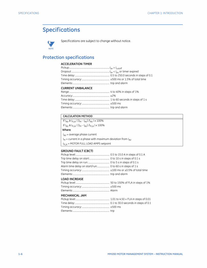
Protection specificationsACCELERATION TIMERPickup:...................................................................... Iav > IcutoffDropout: .................................................................. Iav < Ipu or timer expiredTime delay: ............................................................ 0.5 to 250.0 seconds in steps of 0.1Timing accuracy: ................................................ ±500 ms or 1.5% of total timeElements: ................................................................ trip and alarm
CURRENT UNBALANCERange: ...................................................................... 4 to 40% in steps of 1%Accuracy:................................................................ ±2%Time delay: ............................................................ 1 to 60 seconds in steps of 1 sTiming accuracy: ................................................ ±500 msElements: ................................................................ trip and alarm
GROUND FAULT (CBCT)Pickup level:........................................................... 0.5 to 15.0 A in steps of 0.1 ATrip time delay on start:................................... 0 to 10 s in steps of 0.1 sTrip time delay on run: ..................................... 0 to 5 s in steps of 0.1 sAlarm time delay on start/run:..................... 0 to 60 s in steps of 1 sTiming accuracy: ................................................ ±100 ms or ±0.5% of total timeElements: ................................................................ trip and alarm
LOAD INCREASEPickup level:........................................................... 50 to 150% of FLA in steps of 1%Timing accuracy: ................................................ ±500 msElements: ................................................................ Alarm
MECHANICAL JAMPickup level:........................................................... 1.01 to 4.50 × FLA in steps of 0.01Time delay: ............................................................ 0.1 to 30.0 seconds in steps of 0.1Timing accuracy: ................................................ ±500 msElements: ................................................................ trip
CALCULATION METHOD
If IAV ≥ IFLA: ( [IM - IAV] /IAV ) x 100%
If IAV ≤ IFLA: ( [IM - IAV] /IFLA ) x 100%
Where:
IAV = average phase current
IM = current in a phase with maximum deviation from IAV
IFLA = MOTOR FULL LOAD AMPS setpoint

CHAPTER 1: INTRODUCTION SPECIFICATIONS
MM200 MOTOR MANAGEMENT SYSTEM – INSTRUCTION MANUAL 1–7
THERMAL MODELStandard curve time multiplier: ................... 1 to 15 in steps of 1Thermal overload pickup: ............................... 1.01 to 1.25 in steps of 0.01 x FLAMotor full load current (FLA): ......................... 0.5 to 1000 A in steps of 0.1Motor rated voltage:.......................................... 100 to 690 V ACCurve biasing:....................................................... hot/cold ratio exponential running and stopped cooling
ratesUpdate rate: .......................................................... 3 cyclesHot/cold safe stall ratio: .................................. 1 to 100% in steps of 1%Timing accuracy: ................................................ ±200 ms or ±2% of total time (based on measured value)Elements: ................................................................ trip
THERMISTORSensor types:......................................................... PTC (RHOT = 100 to 30 kohms); NTC (RHOT = 100 to 30 kohms)Timing accuracy: ................................................ ±500 msElements: ................................................................ Trip and alarm
UNDERCURRENTPickup level: ........................................................... 1 to 100% of FLA in steps of 1Time delay:............................................................. 1 to 60 seconds in steps of 1Timing accuracy: ................................................ ±500 msElements: ................................................................ Trip and alarm
POWER FAILURE RESTARTType:.......................................................................... Digital inputPower failure time: ............................................. 0 to 30 seconds in steps of 1Restart time delay: ............................................. 0 to 300 seconds in steps of 1UV detection time accuracy: ......................... ±100 ms or ±5%
User interface specificationsHAND HELD DISPLAY (HHD)Size: ........................................................................... width 153mm, height 102mm, depth 35mmLCD: ........................................................................... 3.5-inch color, 320 by 240 pixelsLED Indicators: ..................................................... 10 LEDsPushbuttons: ......................................................... Start A, Start B, Stop, plus 11 LCD screen display control keysPorts: ......................................................................... USB 2.0 port for laptop computer connectionCable - GCP to Base Unit:................................ Shielded RJ45; Maximum length 6' (1.83m)
BASIC CONTROL PANELSize: ........................................................................... BCP: width 75mm, height 75mm, depth 31mmLED Indicators: ..................................................... 12 LEDsPushbuttons: ......................................................... Start A, Start B, Stop, Reset, Auto, ManualCable - BCP to Base Unit: ................................ Shielded RJ45; Maximum length 6' (1.83m)
Control specificationsPOWER FAILURE RESTARTType:.......................................................................... Digital inputPower failure time: ............................................. 0 to 30 seconds in steps of 1Restart time delay: ............................................. 0 to 300 seconds in steps of 1UV detection time accuracy: ......................... ±100 ms or ±5%
1–8 MM200 MOTOR MANAGEMENT SYSTEM – INSTRUCTION MANUAL
SPECIFICATIONS CHAPTER 1: INTRODUCTION
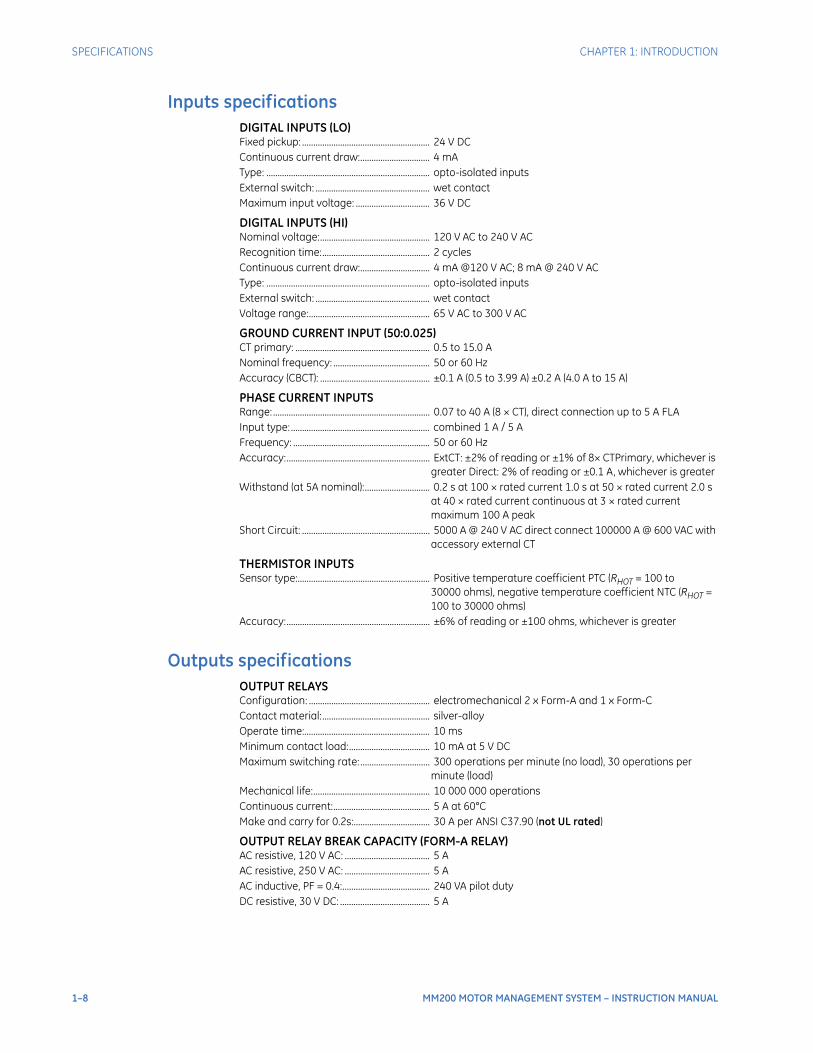
Inputs specificationsDIGITAL INPUTS (LO)Fixed pickup: ......................................................... 24 V DCContinuous current draw:............................... 4 mAType: ......................................................................... opto-isolated inputsExternal switch: ................................................... wet contactMaximum input voltage: ................................. 36 V DC
DIGITAL INPUTS (HI)Nominal voltage:................................................. 120 V AC to 240 V ACRecognition time:................................................ 2 cyclesContinuous current draw:............................... 4 mA @120 V AC; 8 mA @ 240 V ACType: ......................................................................... opto-isolated inputsExternal switch: ................................................... wet contactVoltage range:...................................................... 65 V AC to 300 V AC
GROUND CURRENT INPUT (50:0.025)CT primary: ............................................................ 0.5 to 15.0 ANominal frequency: ........................................... 50 or 60 HzAccuracy (CBCT): ................................................. ±0.1 A (0.5 to 3.99 A) ±0.2 A (4.0 A to 15 A)
PHASE CURRENT INPUTSRange: ...................................................................... 0.07 to 40 A (8 × CT), direct connection up to 5 A FLAInput type: .............................................................. combined 1 A / 5 AFrequency: ............................................................. 50 or 60 HzAccuracy:................................................................ ExtCT: ±2% of reading or ±1% of 8× CTPrimary, whichever is
greater Direct: 2% of reading or ±0.1 A, whichever is greaterWithstand (at 5A nominal):............................. 0.2 s at 100 × rated current 1.0 s at 50 × rated current 2.0 s
at 40 × rated current continuous at 3 × rated current maximum 100 A peak
Short Circuit: ......................................................... 5000 A @ 240 V AC direct connect 100000 A @ 600 VAC with accessory external CT
THERMISTOR INPUTSSensor type:........................................................... Positive temperature coefficient PTC (RHOT = 100 to
30000 ohms), negative temperature coefficient NTC (RHOT = 100 to 30000 ohms)
Accuracy:................................................................ ±6% of reading or ±100 ohms, whichever is greater
Outputs specificationsOUTPUT RELAYSConfiguration: ...................................................... electromechanical 2 x Form-A and 1 x Form-CContact material:................................................ silver-alloyOperate time:........................................................ 10 msMinimum contact load:.................................... 10 mA at 5 V DCMaximum switching rate: ............................... 300 operations per minute (no load), 30 operations per
minute (load)Mechanical life:.................................................... 10 000 000 operationsContinuous current:........................................... 5 A at 60°CMake and carry for 0.2s:.................................. 30 A per ANSI C37.90 (not UL rated)
OUTPUT RELAY BREAK CAPACITY (FORM-A RELAY)AC resistive, 120 V AC: ...................................... 5 AAC resistive, 250 V AC: ...................................... 5 AAC inductive, PF = 0.4:....................................... 240 VA pilot dutyDC resistive, 30 V DC: ........................................ 5 A

CHAPTER 1: INTRODUCTION SPECIFICATIONS
MM200 MOTOR MANAGEMENT SYSTEM – INSTRUCTION MANUAL 1–9
OUTPUT RELAY BREAK CAPACITY (FORM-C RELAY)AC resistive, 120 V AC:....................................... 5 A normally-open, 5 A normally-closedAC resistive, 240 V AC:....................................... 5 A normally-open, 5 A normally-closedAC inductive, PF = 0.4: ....................................... 240 VA pilot dutyDC resistive, 30 V DC: ........................................ 5 A
Power supply specificationsPOWER SUPPLY (LO RANGE)Nominal: .................................................................. 24 V DCRange: ...................................................................... 18 to 36 V DCPower Consumption:......................................... 10 W typical
POWER SUPPLY (HI RANGE)Nominal: .................................................................. 120 to 240 V AC; 125 to 250 V DCRange: ...................................................................... 60 to 300 V AC (50 and 60 Hz); 84 to 250 V DCPower consumption: ......................................... 10 W typicalVoltage withstand: ............................................. 2 × highest nominal voltage for 10 ms
Communications specificationsDEVICENET (COPPER)Modes:...................................................................... slave (125, 250, and 500 kbps)Connector:.............................................................. 5-pin terminalCurrent Draw: ....................................................... 80 mA at 24 VDC
PROFIBUS (COPPER)Modes:...................................................................... DP V0 slave, up to 1.5 MbpsConnector:.............................................................. 5-pin terminal
RS485 PORTPort: ........................................................................... opto-isolatedBaud rates:............................................................. up to 115 kbpsProtocol: .................................................................. Modbus RTU, half-duplexMaximum distance: ........................................... 1200 mIsolation:.................................................................. 2 kV
Testing and certification
TYPE TESTS (TEST NOT PERFORMED FOR AC PSU)
Test Reference Standard Test Level
Dielectric voltage withstand 2.3KV
Impulse voltage withstand EN60255-5 5KV
Damped Oscillatory IEC61000-4-18IEC60255-22-1 2.5KV CM, 1KV DM
Electrostatic Discharge EN61000-4-2/IEC60255-22-2 Level 4
RF immunity EN61000-4-3/IEC60255-22-3 Level 3
Fast Transient Disturbance EN61000-4-4/IEC60255-22-4 Class A
Surge Immunity EN61000-4-5/IEC60255-22-5 Level 3
Conducted RF Immunity EN61000-4-6/IEC60255-22-6 Level 3
Power Frequency Immunity EN61000-4-7/IEC60255-22-7 Class A
Voltage interruptionand Ripple DC IEC60255-11 15% ripple, 200ms interupts
Radiated & Conducted Emissions CISPR11 /CISPR22/ IEC60255-25 Class A
Sinusoidal Vibration IEC60255-21-1 Class 1

1–10 MM200 MOTOR MANAGEMENT SYSTEM – INSTRUCTION MANUAL
SPECIFICATIONS CHAPTER 1: INTRODUCTION
EACThe EAC Technical Regulations (TR) for Machines and Equipment apply to the Customs Union (CU) of the Russian Federation, Belarus, and Kazakhstan
Physical specificationsDIMENSIONSSize: ........................................................................... Base: 78 mm (W) × 90 mm (H) × 113 mm (D) [+ terminals
10mm] BCP: 75 mm (W) × 75 mm (H) × 31 mm (D)Weight (Base):....................................................... 0.5 kg
Shock & Bump IEC60255-21-2 Class 1
Siesmic IEC60255-21-3 Class 2
Power magnetic Immunity IEC61000-4-8 Level 5
Pulse Magnetic Immunity IEC61000-4-9 Level 4
Damped Magnetic Immunity IEC61000-4-10 Level 4
Voltage Dip & interruption IEC61000-4-11 0,40,70% dips,250/300cycle interrupts
Damped Oscillatory IEC61000-4-12 2.5KV CM, 1KV DM
Voltage Ripple IEC61000-4-17 15% ripple
Ingress Protection IEC60529 IP20 (base unit) , IP54 (Control Panel)
Environmental (Cold) IEC60068-2-1 -25C 16 hrs
Environmental (Dry heat) IEC60068-2-2 70C 16hrs
Relative Humidity Cyclic IEC60068-2-30 6day variant 2
UL508 e83849 NKCR
Safety UL C22.2-14 e83849 NKCR7
UL1053 e83849 NKCR
CERTIFICATION
APPROVAL
Applicable Council Directive According to
Low voltage directive EN60255-5, EN60255-27
CE compliance EMC Directive EN60255-26 / EN50263
UL508
North America cULus UL1053
C22.2.No 14
EAC Machines and Equipment TR CU 010/2011
ISO: Manufactured under a registered quality program
ISO9001
Item Description
Country of origin Spain or Canada; see label on the unit
Date of manufacture See label on the side of the MM200 unit
Declaration of Conformity and/or Certificate of Conformity
Available on request
TYPE TESTS (TEST NOT PERFORMED FOR AC PSU)
Test Reference Standard Test Level
CHAPTER 1: INTRODUCTION SPECIFICATIONS
MM200 MOTOR MANAGEMENT SYSTEM – INSTRUCTION MANUAL 1–11
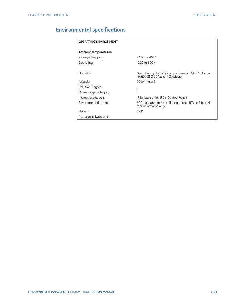
Environmental specifications
OPERATING ENVIRONMENT
Ambient temperatures:
Storage/shiipping: - 40C to 90C *
Operating: -20C to 60C *
Humidity Operating up to 95% (non condensing) @ 55C (As per IEC60068-2-30 Variant 2, 6days)
Altitude: 2000m (max)
Pollution Degree: II
Overvoltage Category: II
Ingress protection: IP20 (base unit) , IP54 (Control Panel)
Environmental rating; 60C surrounding Air ,pollution degree II,Type 1 (panel mount versions only)
Noise: 0 dB
* 1" around base unit

1–12 MM200 MOTOR MANAGEMENT SYSTEM – INSTRUCTION MANUAL
SPECIFICATIONS CHAPTER 1: INTRODUCTION
MM200 MOTOR MANAGEMENT SYSTEM – INSTRUCTION MANUAL 2–1
MM200 Motor Management System
Chapter 2: Installation
GEGrid Solutions
Installation
Mechanical installation
This section describes the mechanical installation of the MM200 system, including dimensions for mounting.
DimensionsThe MM200 is packaged in a fixed format divided into three specific sections.The dimensions of the MM200 are shown below. Additional dimensions for mounting are shown in the following sections.
2–2 MM200 MOTOR MANAGEMENT SYSTEM – INSTRUCTION MANUAL
MECHANICAL INSTALLATION CHAPTER 2: INSTALLATION
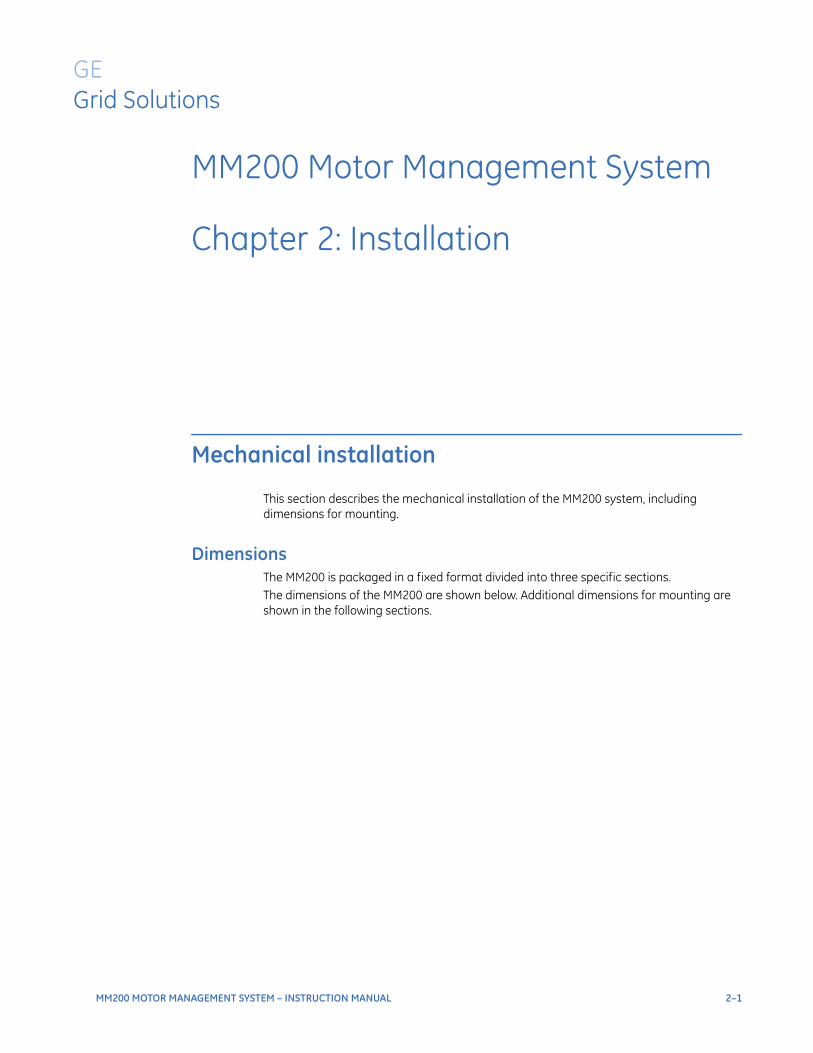
Figure 2-1: MM200 dimensions
Product identificationThe product identification label is located on the side panel of the MM200. This label indicates the product model, serial number, firmware revision, and date of manufacture.
Figure 2-2: MM200 Identification label
888748A1.CDR
Model:
Serial Number:
Firmware: Mfg.Date:

CHAPTER 2: INSTALLATION MECHANICAL INSTALLATION
MM200 MOTOR MANAGEMENT SYSTEM – INSTRUCTION MANUAL 2–3
Figure 2-3: MM200 ratings label
MountingThe MM200 is DIN rail mounted.The standard DIN rail mounting is illustrated below. The DIN rail conforms to EN 50022.
CAUTION: To avoid the potential for personal injury due to fire hazards, ensure the unit is mounted in a safe location and/or within an appropriate enclosure.
Figure 2-4: DIN rail mounting
2–4 MM200 MOTOR MANAGEMENT SYSTEM – INSTRUCTION MANUAL
ELECTRICAL INSTALLATION CHAPTER 2: INSTALLATION
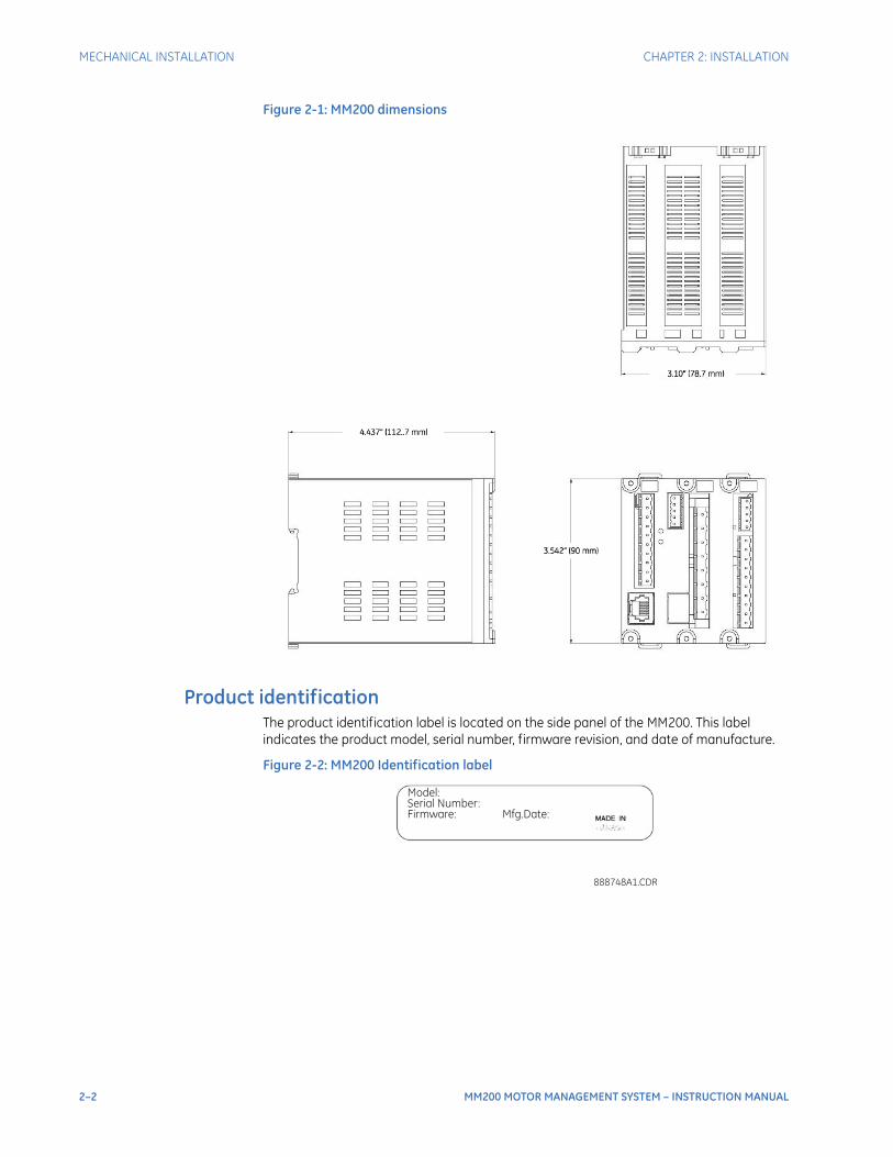
Electrical installation
This section describes the electrical installation of the MM200 system. An overview of the MM200 terminal connections is shown below.
CAUTION: MM200 is not to be used in any way other than described in this manual.
Figure 2-5: MM200 terminal connection overview
A Modbus RTU RS485 port, a thermistor input, and a 50:0.025 CBCT input are provided. Profibus and Devicenet are provided as options.
Table 2-1: Slot position
Figure 2-6: MM200 terminal connection torque rating
Slot Type
A PSU/Inputs/Control Panel
B CPU/CTs
C Outputs/CBCT/Thermistor/RS485
Control Panel
Profibus or DeviceNet
Optional fieldbus protocols
888740A2.CDRCTs
PSU
Inputs
RS485Thermistor
CBCT
2 x Form A1 x Form C
connector screw torque
CT 4.5 lb-in
IPS, output 5.0 lb-in
Fieldbus, 3.0 lb-inThermistor & RS485
CHAPTER 2: INSTALLATION ELECTRICAL INSTALLATION
MM200 MOTOR MANAGEMENT SYSTEM – INSTRUCTION MANUAL 2–5
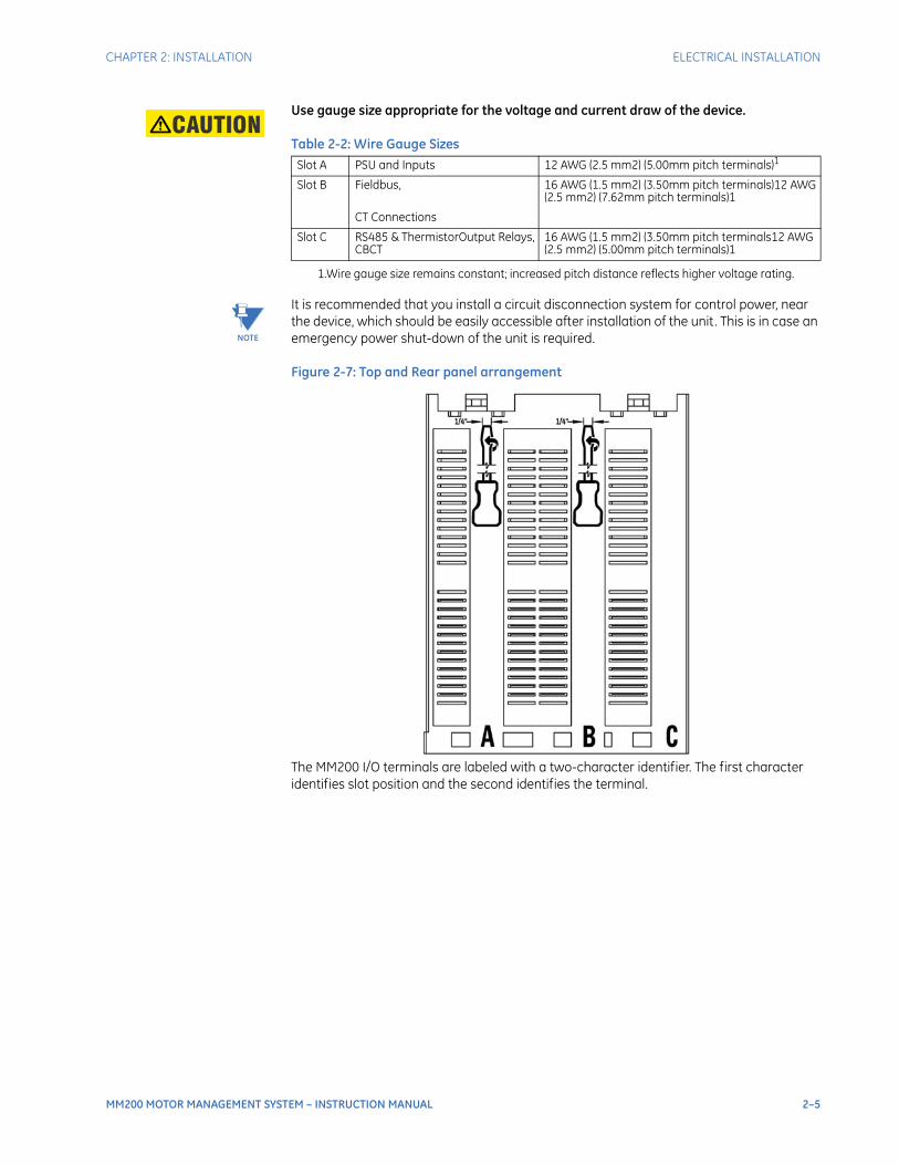
CAUTION: Use gauge size appropriate for the voltage and current draw of the device.
Table 2-2: Wire Gauge Sizes
NOTE
NOTE: It is recommended that you install a circuit disconnection system for control power, near the device, which should be easily accessible after installation of the unit. This is in case an emergency power shut-down of the unit is required.
Figure 2-7: Top and Rear panel arrangement
The MM200 I/O terminals are labeled with a two-character identifier. The first character identifies slot position and the second identifies the terminal.
Slot A PSU and Inputs 12 AWG (2.5 mm2) (5.00mm pitch terminals)1
1.Wire gauge size remains constant; increased pitch distance reflects higher voltage rating.
Slot B Fieldbus,
CT Connections
16 AWG (1.5 mm2) (3.50mm pitch terminals)12 AWG (2.5 mm2) (7.62mm pitch terminals)1
Slot C RS485 & ThermistorOutput Relays, CBCT
16 AWG (1.5 mm2) (3.50mm pitch terminals12 AWG (2.5 mm2) (5.00mm pitch terminals)1
2–6 MM200 MOTOR MANAGEMENT SYSTEM – INSTRUCTION MANUAL
ELECTRICAL INSTALLATION CHAPTER 2: INSTALLATION
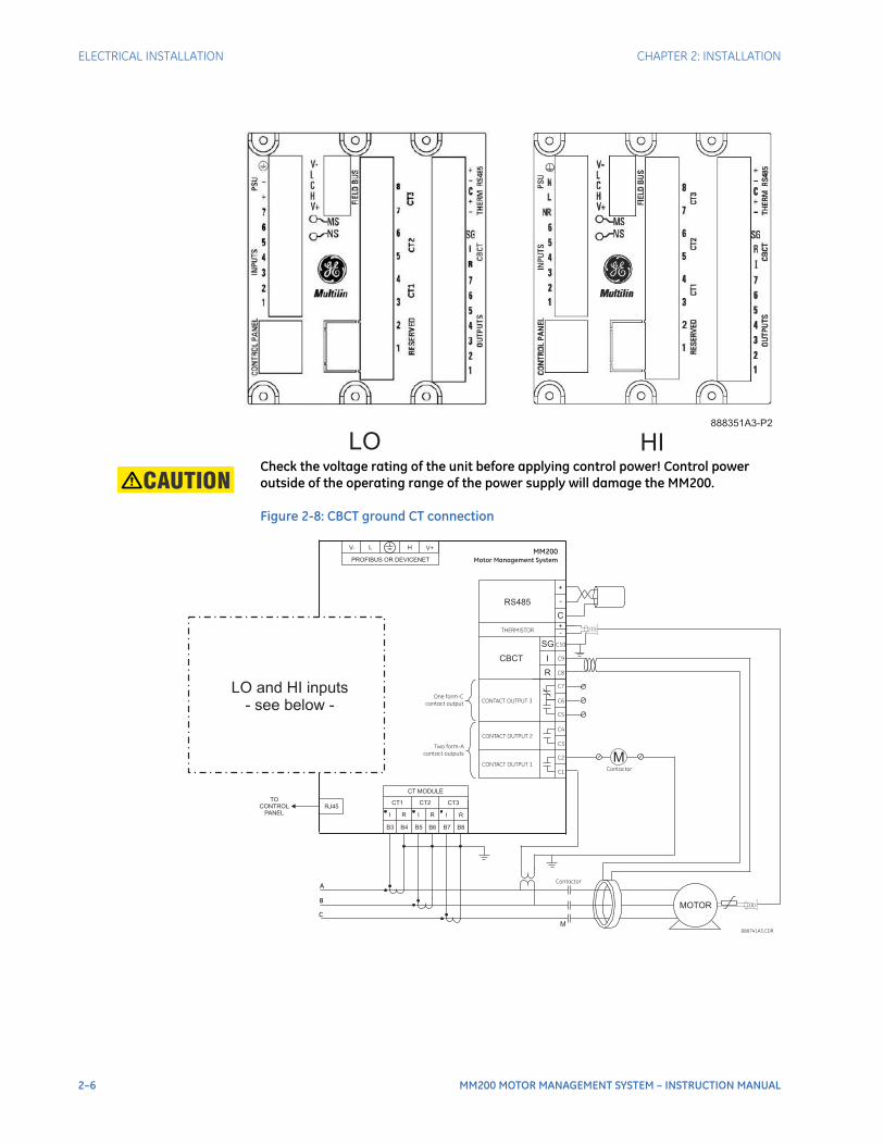
CAUTION: Check the voltage rating of the unit before applying control power! Control power outside of the operating range of the power supply will damage the MM200.
Figure 2-8: CBCT ground CT connection
HILO888351A3-P2
888741A3.CDR
A
C
B
Contactor
Contactor
TOCONTROL
PANEL
C1
C2
C4
C3
C5
C6
MM200
Motor Management System
C8
C9
C10
C7
Two form-A
contact outputs
CONTACT OUTPUT 2
One form-C
contact output
CONTACT OUTPUT 1
CONTACT OUTPUT 3
THERMISTOR
CBCT
RS485
R
I
-+
-
+
C
B3 B4 B5 B6 B7 B8
I R I R I R
CT1 CT2 CT3
CT MODULE
RJ45
PROFIBUS OR DEVICENET
V- L H V+
MOTOR
M
M
SG
LO and HI inputs- see below -

CHAPTER 2: INSTALLATION ELECTRICAL INSTALLATION
MM200 MOTOR MANAGEMENT SYSTEM – INSTRUCTION MANUAL 2–7
Figure 2-9: CBCT ground CT connection - LO and HI inputs
The exact placement of a zero-sequence CT to detect only ground fault current is shown below. If the core balance CT is placed over shielded cable, capacitive coupling of phase current into the cable shield during motor starts may be detected as ground current unless the shield wire is also passed through the CT window. Twisted-pair cabling on the zero-sequence CT is recommended.
Figure 2-10: Core balance ground CT installation, shielded cable
M
-+
A1
A2
A4
A3
A5
A6
A8
A9
A10
A7
+-
24 VD
C C
ON
TAC
T INP
UTS
CO
NTR
OL
PO
WE
R (V
DC
)
CONTROLPOWER24 VDC
FIELD STOP
FIELD START
RESET
M
N
L
A1
A2
A4
A3
A5
A6
A8
A9
A10
L
N
VAC
CO
NTA
CT IN
PU
TS
CO
NTR
OL
PO
WE
R (VA
C)
CONTROLPOWER
VAC
FIELD STOP
FIELD START
RESET
NR
LO HI
888742A3.cdr
RETURN
NOTE: AC power and AC input wiring shown.
POWER CABLE
TO MOTOR
TO STARTER
GROUND BUS
CABLE LUGS
TO SOURCE
TERMINATION
(TWISTED PAIR)
SPLIT-BOLT CONNECTOR
888712A1.CDR
CORE BALANCE CT
SECONDARY CONNECTION
TO MM200 IED
IMPORTANT: FOR SHIELDED
CABLE, THE GROUND WIRE
MUST PASS THROUGH THE
CT WINDOW.
50:0.025 CORE BALANCE CT
FOR GROUND SENSING
STRESS CONE
SHIELD GROUND
CONNECTION
BOTTOM OF
MOTOR STARTER
COMPARTMENT
2–8 MM200 MOTOR MANAGEMENT SYSTEM – INSTRUCTION MANUAL
ELECTRICAL INSTALLATION CHAPTER 2: INSTALLATION
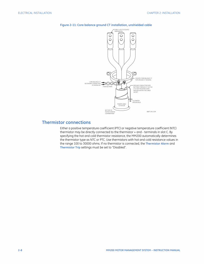
Figure 2-11: Core balance ground CT installation, unshielded cable
Thermistor connectionsEither a positive temperature coefficient (PTC) or negative temperature coefficient (NTC) thermistor may be directly connected to the thermistor + and - terminals in slot C. By specifying the hot and cold thermistor resistance, the MM200 automatically determines the thermistor type as NTC or PTC. Use thermistors with hot and cold resistance values in the range 100 to 30000 ohms. If no thermistor is connected, the Thermistor Alarm and Thermistor Trip settings must be set to “Disabled”.
POWER CABLE
TO MOTOR
50:0.025 CORE BALANCE CT
FOR GROUND CT SENSING
TO STARTER
GROUND BUS
CABLE LUGS TO SOURCE
TERMINATION
(TWISTED-PAIR)
888713A1.CDR
GROUND CONDUCTOR DOES
NOT PASS THROUGH CT, AS THE
CT IS NOT MOUNTED OVER
GROUND WITHIN THE CABLE
JACKET.
BOTTOM OF
MOTOR STARTER
COMPARTMENT
CORE BALANCE CT
SECONDARY CONNECTION
TO MM200 IED
CHAPTER 2: INSTALLATION ELECTRICAL INSTALLATION
MM200 MOTOR MANAGEMENT SYSTEM – INSTRUCTION MANUAL 2–9
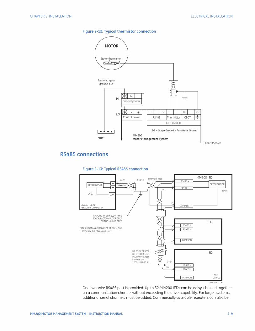
Figure 2-12: Typical thermistor connection
RS485 connections
Figure 2-13: Typical RS485 connection
One two-wire RS485 port is provided. Up to 32 MM200 IEDs can be daisy-chained together on a communication channel without exceeding the driver capability. For larger systems, additional serial channels must be added. Commercially available repeaters can also be
– C –+
CPU module
MM200
Motor Management System
To switchgear
ground bus
888743A2.CDR
R I
RS485 Thermistor CBCT
+
Stator thermistor
MOTOR
Control power
- +
SG = Surge Ground = Functional Ground
SGLO
Control power
N L
HI
SCADA, PLC, OR
PERSONAL COMPUTER
COM
OPTOCOUPLER
DATA
MM200 IEDSHIELD
888745A1.CDR
UP TO 32 MM200
OR OTHER IEDs,
MAXIMUM CABLE
LENGTH OF
1200 m (4000 ft.)
LAST
DEVICE
(*) TERMINATING IMPEDANCE AT EACH END
(typically 120 ohms and 1 nF)
TWISTED PAIR
ZT
(*)
RS485 +
RS485 -
COMMON
RS485 +
RS485 -
COMMON
IED
RS485 +
IED
RS485 -
COMMON
GROUND THE SHIELD AT THE
SCADA/PLC/COMPUTER ONLY
OR THE MM200 ONLY
DATA
OPTOCOUPLER
ZT
(*) +
-
C

2–10 MM200 MOTOR MANAGEMENT SYSTEM – INSTRUCTION MANUAL
ELECTRICAL INSTALLATION CHAPTER 2: INSTALLATION
used to add more than 32 relays on a single channel. Suitable cable should have a characteristic impedance of 120 ohms and total wire length should not exceed 1200 meters (4000 ft.). Commercially available repeaters will allow for transmission distances greater than 1200 meters.Voltage differences between remote ends of the communication link are not uncommon. For this reason, surge protection devices are internally installed across all RS485 terminals. Internally, an isolated power supply with an optocoupled data interface is used to prevent noise coupling.
CAUTION: To ensure that all devices in a daisy-chain are at the same potential, it is imperative that the common terminals of each RS485 port are tied together and grounded only once, at the master or at the MM200. Failure to do so may result in intermittent or failed communications.
The source computer/PLC/SCADA system should have similar transient protection devices installed, either internally or externally. Ground the shield at one point only, as shown in the figure above, to avoid ground loops.Correct polarity is also essential. The MM200 IEDs must be wired with all the positive (+) terminals connected together and all the negative (–) terminals connected together. Each relay must be daisy-chained to the next one. Avoid star or stub connected configurations. The last device at each end of the daisy-chain should be terminated with a 120 ohm ¼ watt resistor in series with a 1 nF capacitor across the positive and negative terminals. Observing these guidelines will ensure a reliable communication system immune to system transients.
Protection
Phase current inputs Figure 2-14: Typical phase current input connections
The MM200 has three channels for phase current inputs, each with an isolating transformer. The phase CTs should be chosen so the FLA is not less than 50% of the rated phase CT primary. Ideally, the phase CT primary should be chosen such that the FLA is
A
C
B
Contactor
B3 B4 B6B5
Phase current inputs
MM200
Motor Management System
To switchgear
ground bus
888714A2.CDR
B7 B8
CT1 CT2 CT3
Control power
+-
A10 A9 A8
Control power
N LHI
A10 A9 A8
LO
CHAPTER 2: INSTALLATION ELECTRICAL INSTALLATION
MM200 MOTOR MANAGEMENT SYSTEM – INSTRUCTION MANUAL 2–11
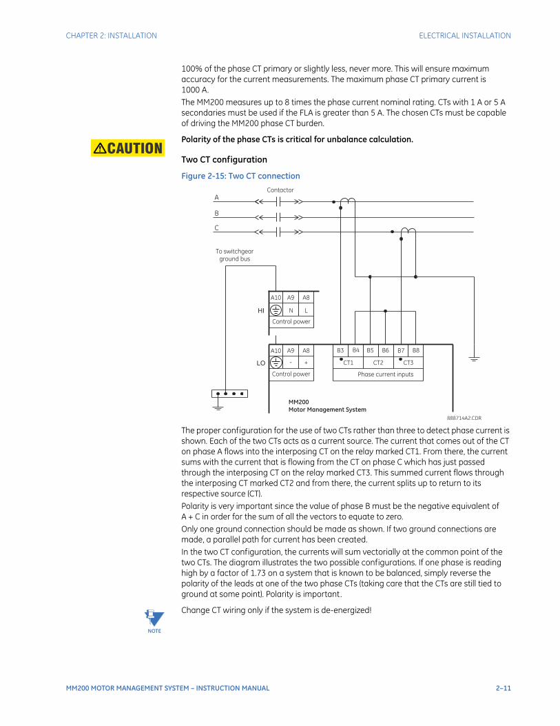
100% of the phase CT primary or slightly less, never more. This will ensure maximum accuracy for the current measurements. The maximum phase CT primary current is 1000 A.The MM200 measures up to 8 times the phase current nominal rating. CTs with 1 A or 5 A secondaries must be used if the FLA is greater than 5 A. The chosen CTs must be capable of driving the MM200 phase CT burden.
CAUTION: Polarity of the phase CTs is critical for unbalance calculation.
Two CT configuration
Figure 2-15: Two CT connection
The proper configuration for the use of two CTs rather than three to detect phase current is shown. Each of the two CTs acts as a current source. The current that comes out of the CT on phase A flows into the interposing CT on the relay marked CT1. From there, the current sums with the current that is flowing from the CT on phase C which has just passed through the interposing CT on the relay marked CT3. This summed current flows through the interposing CT marked CT2 and from there, the current splits up to return to its respective source (CT).Polarity is very important since the value of phase B must be the negative equivalent of A + C in order for the sum of all the vectors to equate to zero.Only one ground connection should be made as shown. If two ground connections are made, a parallel path for current has been created.In the two CT configuration, the currents will sum vectorially at the common point of the two CTs. The diagram illustrates the two possible configurations. If one phase is reading high by a factor of 1.73 on a system that is known to be balanced, simply reverse the polarity of the leads at one of the two phase CTs (taking care that the CTs are still tied to ground at some point). Polarity is important.
NOTE
NOTE: Change CT wiring only if the system is de-energized!
A
C
B
Contactor
B3 B4 B6B5
Phase current inputs
MM200
Motor Management System
To switchgear
ground bus
888714A2.CDR
B7 B8
CT1 CT2 CT3
Control power
+-
A10 A9 A8
Control power
N LHI
A10 A9 A8
LO
2–12 MM200 MOTOR MANAGEMENT SYSTEM – INSTRUCTION MANUAL
ELECTRICAL INSTALLATION CHAPTER 2: INSTALLATION
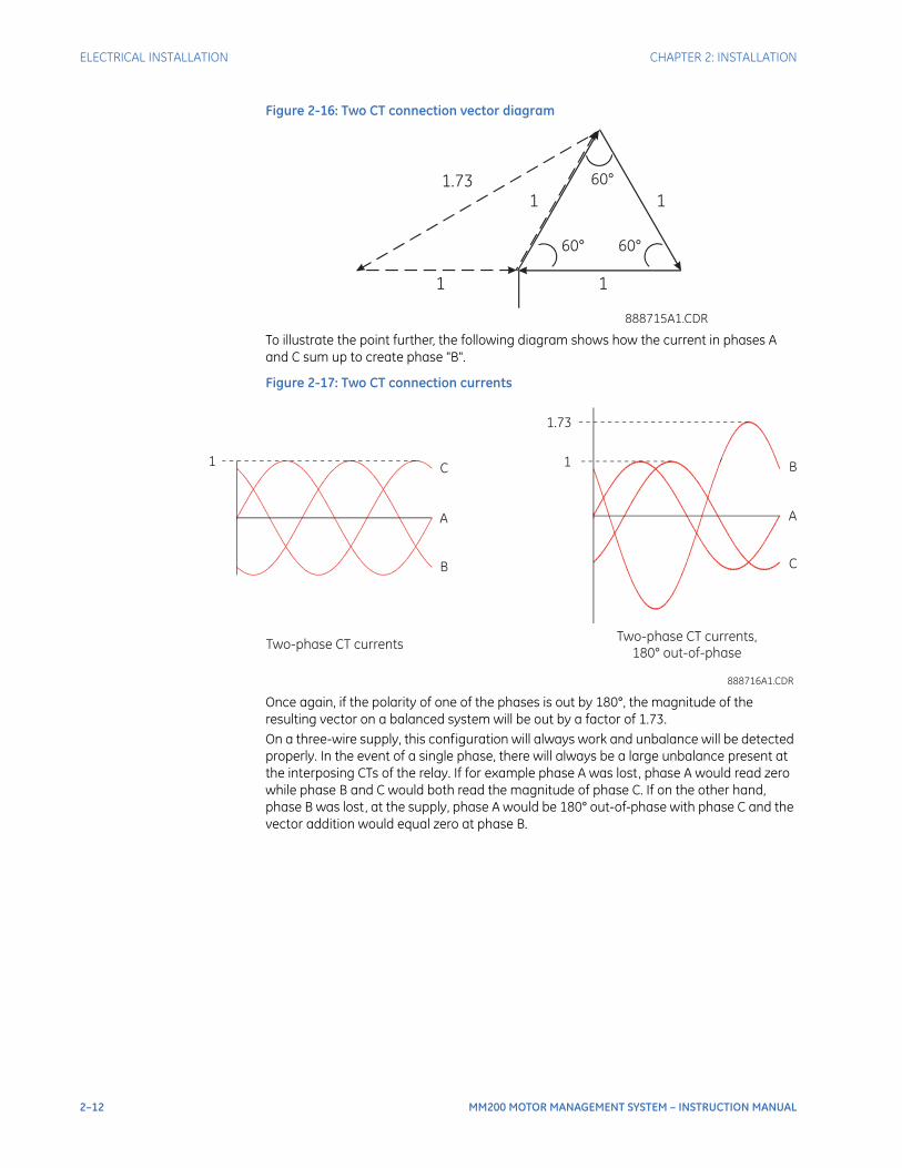
Figure 2-16: Two CT connection vector diagram
To illustrate the point further, the following diagram shows how the current in phases A and C sum up to create phase "B".
Figure 2-17: Two CT connection currents
Once again, if the polarity of one of the phases is out by 180°, the magnitude of the resulting vector on a balanced system will be out by a factor of 1.73.On a three-wire supply, this configuration will always work and unbalance will be detected properly. In the event of a single phase, there will always be a large unbalance present at the interposing CTs of the relay. If for example phase A was lost, phase A would read zero while phase B and C would both read the magnitude of phase C. If on the other hand, phase B was lost, at the supply, phase A would be 180° out-of-phase with phase C and the vector addition would equal zero at phase B.
888715A1.CDR
1.73
1 1
1 1
60°
60° 60°
888716A1.CDR
1C
A
B
1.73
1B
A
C
Two-phase CT currentsTwo-phase CT currents,
180° out-of-phase

CHAPTER 2: INSTALLATION ELECTRICAL INSTALLATION
MM200 MOTOR MANAGEMENT SYSTEM – INSTRUCTION MANUAL 2–13
Input/output
Type IO_Cconnections
Figure 2-18: Typical wiring for IO connectors
Figure 2-19: LO and HI input connections
The MM200 contains two Form-A contact output relays, one Form-C contact output relay, and seven digital inputs.Contact inputs can be programmed to any of the input functions, such as field stop. The exception is that contactor A status is fixed as the first contact input, and contactor B status (where used) is fixed as the second contact input.
888741A3.CDR
A
C
B
Contactor
Contactor
TOCONTROL
PANEL
C1
C2
C4
C3
C5
C6
MM200
Motor Management System
C8
C9
C10
C7
Two form-A
contact outputs
CONTACT OUTPUT 2
One form-C
contact output
CONTACT OUTPUT 1
CONTACT OUTPUT 3
THERMISTOR
CBCT
RS485
R
I
-+
-
+
C
B3 B4 B5 B6 B7 B8
I R I R I R
CT1 CT2 CT3
CT MODULE
RJ45
PROFIBUS OR DEVICENET
V- L H V+
MOTOR
M
M
SG
LO and HI inputs- see below -
M
-
+
A1
A2
A4
A3
A5
A6
A8
A9
A10
A7
+
-
24
VD
CC
ON
TA
CT
INP
UT
S
CO
NT
RO
L
PO
WE
R(V
DC
)
CONTROLPOWER24 VDC
FIELD STOP
FIELD START
RESET
M
N
L
A1
A2
A4
A3
A5
A6
A8
A9
A10
L
N
VA
CC
ON
TA
CT
INP
UT
S
CO
NT
RO
L
PO
WE
R(V
AC
)
CONTROLPOWER
VAC
FIELD STOP
FIELD START
RESET
NR
LO HI
888742A1.cdr
RETURN
NOTE: AC power and AC input wiring shown.Connect NR to Neutral if DC power supply used.
2–14 MM200 MOTOR MANAGEMENT SYSTEM – INSTRUCTION MANUAL
ELECTRICAL INSTALLATION CHAPTER 2: INSTALLATION
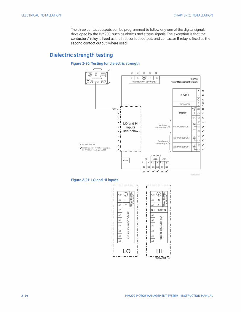
The three contact outputs can be programmed to follow any one of the digital signals developed by the MM200, such as alarms and status signals. The exception is that the contactor A relay is fixed as the first contact output, and contactor B relay is fixed as the second contact output (where used).
Dielectric strength testingFigure 2-20: Testing for dielectric strength
Figure 2-21: LO and HI inputs
Do not HI-POT test
HI-POT test at 1.9 kV AC for 1 second, or
1.6 kV AC for 1 minute (per UL 508)
LINE FAULT
ON
POWER FAULT RESET
kV
VOLTAGE ADJUST HV ON
DIELECTRIC STRENGTH TESTER
BLACK RED
888738A2.CDR
C1
C2
C4
C3
C5
C6
MM200
Motor Management System
C8
C9
C10
C7
Two form-A
contact outputs
CONTACT OUTPUT 2
One form-C
contact output
CONTACT OUTPUT 1
CONTACT OUTPUT 3
THERMISTOR
CBCT
RS485
R
I
-+
-
+
C
B3 B4 B5 B6 B7 B8
I R I R I R
CT1 CT2 CT3
CT MODULE
RJ45
PROFIBUS OR DEVICENET
V- L H V+
A10
LO and HIinputs
- see below -
A1
A2
A4
A3
A5
A6
A8
A9
A10
A7
+
-
24
VD
CC
ON
TA
CT
INP
UT
S
CO
NT
RO
L
PO
WE
R(V
DC
)
A1
A2
A4
A3
A5
A6
A8
A9
A10
L
N
VA
CC
ON
TA
CT
INP
UT
S
CO
NT
RO
L
PO
WE
R(V
AC
)
NR
LO HI888742B1.cdr
RETURN

CHAPTER 2: INSTALLATION STARTER TYPES
MM200 MOTOR MANAGEMENT SYSTEM – INSTRUCTION MANUAL 2–15
It may be required to test a complete motor starter for dielectric strength (“flash” or “HI-POT”) with the MM200 installed. The MM200 is rated for 1.9 kV AC for 1 second, or 1.6 kV AC for 1 minute (per UL 508) isolation between relay contacts, CT inputs, VT inputs and the surge ground terminal SG. Some precautions are required to prevent damage to the MM200 during these tests.The CT inputs, control power, and output relays do not require any special precautions. Low voltage inputs (less than 30 volts), RTDs, and RS485 communication ports are not to be tested for dielectric strength under any circumstance (see above).
Starter types
Full-voltage non-reversing starterFigure 2-22: Full-voltage non-reversing starter wiring
888741A3.CDR
A
C
B
Contactor
Contactor
TOCONTROL
PANEL
C1
C2
C4
C3
C5
C6
MM200
Motor Management System
C8
C9
C10
C7
Two form-A
contact outputs
CONTACT OUTPUT 2
One form-C
contact output
CONTACT OUTPUT 1
CONTACT OUTPUT 3
THERMISTOR
CBCT
RS485
R
I
-+
-
+
C
B3 B4 B5 B6 B7 B8
I R I R I R
CT1 CT2 CT3
CT MODULE
RJ45
PROFIBUS OR DEVICENET
V- L H V+
MOTOR
M
M
SG
LO and HI inputs- see below -
2–16 MM200 MOTOR MANAGEMENT SYSTEM – INSTRUCTION MANUAL
STARTER TYPES CHAPTER 2: INSTALLATION
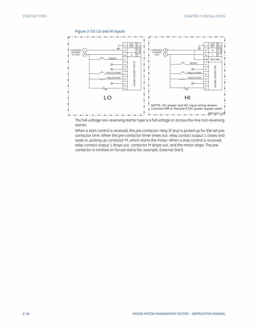
Figure 2-23: LO and HI inputs
The full-voltage non-reversing starter type is a full voltage or across-the-line non-reversing starter.When a start control is received, the pre-contactor relay (if any) is picked up for the set pre-contactor time. When the pre-contactor timer times out, relay contact output 1 closes and seals-in, picking up contactor M, which starts the motor. When a stop control is received, relay contact output 1 drops out, contactor M drops out, and the motor stops. The pre-contactor is omitted on forced starts (for example, External Start).
M
-
+
A1
A2
A4
A3
A5
A6
A8
A9
A10
A7
+
-
24
VD
CC
ON
TA
CT
INP
UT
S
CO
NT
RO
L
PO
WE
R(V
DC
)
CONTROLPOWER24 VDC
FIELD STOP
FIELD START
RESET
M
N
L
A1
A2
A4
A3
A5
A6
A8
A9
A10
L
N
VA
CC
ON
TA
CT
INP
UT
S
CO
NT
RO
L
PO
WE
R(V
AC
)
CONTROLPOWER
VAC
FIELD STOP
FIELD START
RESET
NR
LO HI
888742A1.cdr
RETURN
NOTE: AC power and AC input wiring shown.Connect NR to Neutral if DC power supply used.
CHAPTER 2: INSTALLATION STARTER TYPES
MM200 MOTOR MANAGEMENT SYSTEM – INSTRUCTION MANUAL 2–17
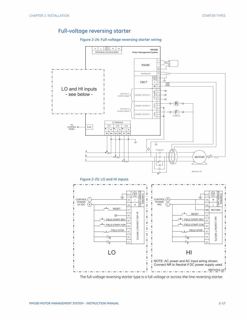
Full-voltage reversing starterFigure 2-24: Full-voltage reversing starter wiring
Figure 2-25: LO and HI inputs
The full-voltage reversing starter type is a full voltage or across-the-line reversing starter.
888705A4.CDR
A
C
B
Contactor
ContactorC1
C2
C4
C3
C5
C6
MM200
Motor Management System
C8
C9
C10
C7
Two form-A
contact outputs
CONTACT OUTPUT 2
One form-C
contact output
CONTACT OUTPUT 1
CONTACT OUTPUT 3
THERMISTOR
CBCT
RS485
R
I
-+
-
+
C
B3 B4 B5 B6 B7 B8
I R I R I R
CT1 CT2 CT3
CT MODULE
RJ45TO
CONTROLPANEL
PROFIBUS OR DEVICENET
V- L H V+
MOTOR
F
F
R
R
LO and HI inputs- see below -
F
-
+
A1
A2
A4
A3
A5
A6
A8
A9
A10
A7
+
-
24
VD
CC
ON
TA
CT
INP
UT
S
CO
NT
RO
L
PO
WE
R(V
DC
)
CONTROLPOWER24 VDC
FIELD STOP
RESET
F
N
L
A1
A2
A4
A3
A5
A6
A8
A9
A10
L
N
VA
CC
ON
TA
CT
INP
UT
S
CO
NT
RO
L
PO
WE
R(V
AC
)
CONTROLPOWER
VAC
FIELD STOP
RESET
NR
LO HI
888742A2.cdr
RETURN
NOTE: AC power and AC input wiring shown.Connect NR to Neutral if DC power supply used.
R R
FIELD START REV
FIELD START FOR
FIELD START REV
FIELD START FOR
2–18 MM200 MOTOR MANAGEMENT SYSTEM – INSTRUCTION MANUAL
STARTER TYPES CHAPTER 2: INSTALLATION
When a start A (forward) control is received, the pre-contactor relay (if any) is picked up for the set pre-contactor time. When the pre-contactor timer times out, relay1 picks up and seals-in, picking up contactor F, which starts the motor in the forward direction. When a start B (reverse) control is received, relay1 drops out, and contactor F drops out. When the contactor F Off status is received, the starter waits for the set transfer time to allow the motor to slow or stop. When the transfer time timer times out, relay2 picks up and seals-in, picking up contactor R, which starts the motor in the reverse direction. When a stop control is received, relays 1 and 2 drop out, contactor F and R drop out, and the motor stops. The starter logic is fully symmetrical between forward and reverse.When a contact input has its function set to forward limit, and that contact closes, relay1 will drop out, stopping any forward rotation. When a contact input has its function set to reverse limit, and that contact closes, relay2 will drop out, stopping any reverse rotation. The pre-contactor is omitted on forced starts (for example, External Start). Forced starts are not supervised by this starter transfer timer – any external starting circuit must itself respect fast direction change restrictions.
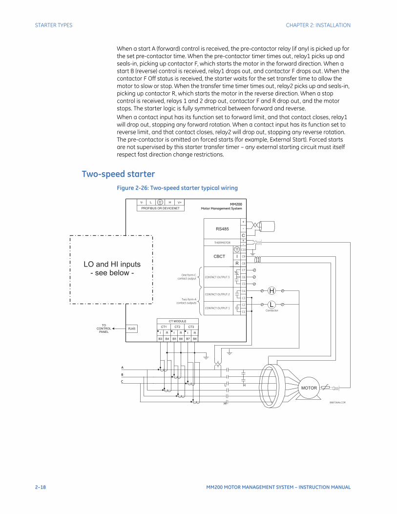
Two-speed starterFigure 2-26: Two-speed starter typical wiring
888706A4.CDR
A
C
B
ContactorC1
C2
C4
C3
C5
C6
MM200
Motor Management System
C8
C9
C10
C7
Two form-A
contact outputs
CONTACT OUTPUT 2
One form-C
contact output
CONTACT OUTPUT 1
CONTACT OUTPUT 3
THERMISTOR
CBCT
RS485
R
I
-+
-
+
C
B3 B4 B5 B6 B7 B8
I R I R I R
CT1 CT2 CT3
CT MODULE
RJ45TO
CONTROLPANEL
PROFIBUS OR DEVICENET
V- L H V+
MOTOR
L
L
H
H
H
LO and HI inputs- see below -
CHAPTER 2: INSTALLATION STARTER TYPES
MM200 MOTOR MANAGEMENT SYSTEM – INSTRUCTION MANUAL 2–19
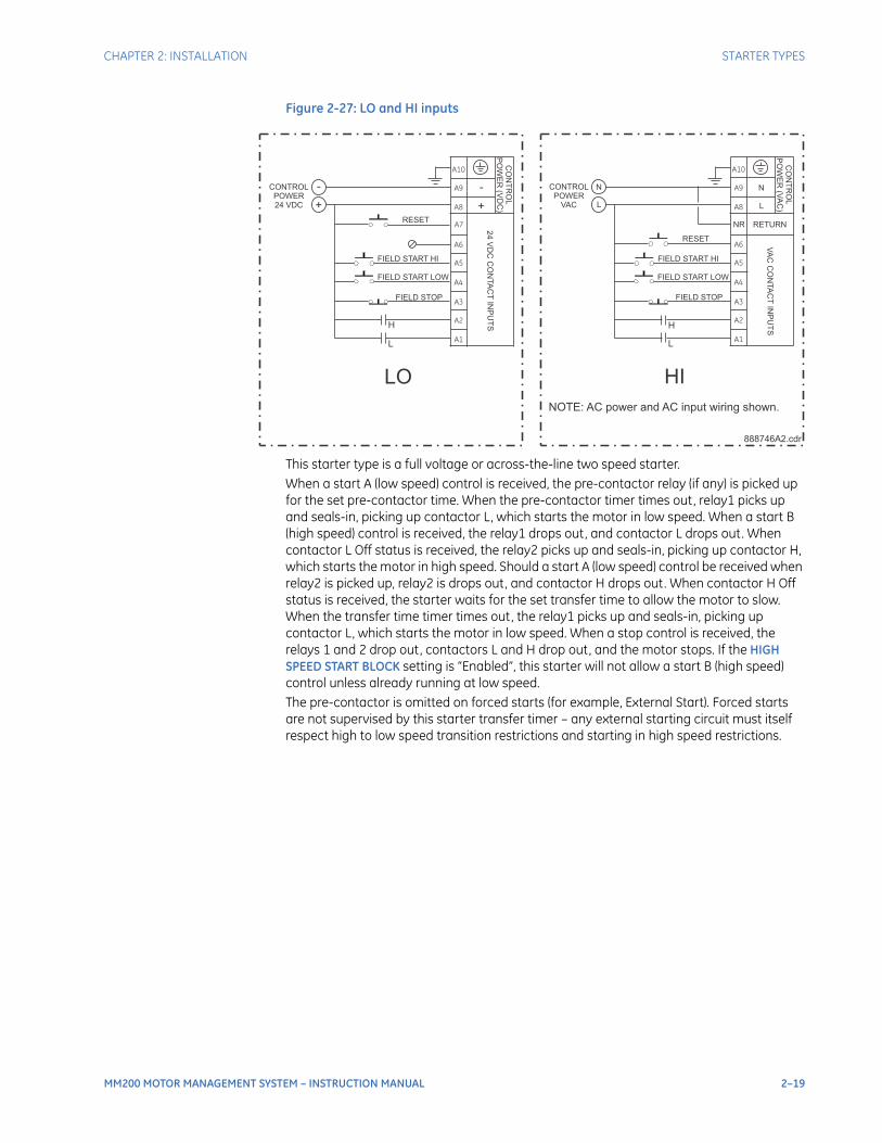
Figure 2-27: LO and HI inputs
This starter type is a full voltage or across-the-line two speed starter.When a start A (low speed) control is received, the pre-contactor relay (if any) is picked up for the set pre-contactor time. When the pre-contactor timer times out, relay1 picks up and seals-in, picking up contactor L, which starts the motor in low speed. When a start B (high speed) control is received, the relay1 drops out, and contactor L drops out. When contactor L Off status is received, the relay2 picks up and seals-in, picking up contactor H, which starts the motor in high speed. Should a start A (low speed) control be received when relay2 is picked up, relay2 is drops out, and contactor H drops out. When contactor H Off status is received, the starter waits for the set transfer time to allow the motor to slow. When the transfer time timer times out, the relay1 picks up and seals-in, picking up contactor L, which starts the motor in low speed. When a stop control is received, the relays 1 and 2 drop out, contactors L and H drop out, and the motor stops. If the HIGH SPEED START BLOCK setting is “Enabled”, this starter will not allow a start B (high speed) control unless already running at low speed.The pre-contactor is omitted on forced starts (for example, External Start). Forced starts are not supervised by this starter transfer timer – any external starting circuit must itself respect high to low speed transition restrictions and starting in high speed restrictions.
L
-+
A1
A2
A4
A3
A5
A6
A8
A9
A10
A7
+-
24 VD
C C
ON
TAC
T INP
UTS
CO
NTR
OL
PO
WE
R (V
DC
)
CONTROLPOWER24 VDC
FIELD STOP
FIELD START LOW
RESET
L
N
L
A1
A2
A4
A3
A5
A6
A8
A9
A10
L
N
VAC
CO
NTA
CT IN
PU
TS
CO
NTR
OL
PO
WE
R (VA
C)
CONTROLPOWER
VAC
FIELD STOP
RESET
NR
LO HI
888746A2.cdr
RETURN
NOTE: AC power and AC input wiring shown.
H H
FIELD START HI
FIELD START LOW
FIELD START HI

2–20 MM200 MOTOR MANAGEMENT SYSTEM – INSTRUCTION MANUAL
GENERAL MAINTENANCE CHAPTER 2: INSTALLATION
General Maintenance
The MM200 requires minimal maintenance. As a microprocessor-based relay, its characteristics do not change over time. The expected service life of an MM200 is 20 years when the environment and electrical conditions are within stated specifications.While the MM200 performs continual self-tests, it is recommended that maintenance be scheduled with other system maintenance. This maintenance can involve in-service, out-of-service, or unscheduled maintenance.
In-service maintenance1. Visual verification of the analog values integrity, such as voltage and current (in
comparison to other devices on the corresponding system).
2. Visual verification of active alarms, relay display messages, and LED indications.
3. Visual inspection for any damage, corrosion, dust, or loose wires.
Out-of-service maintenance1. Check wiring connections for firmness.
2. Analog values (currents, voltages, RTDs, analog inputs) injection test and metering accuracy verification. Calibrated test equipment is required.
3. Protection elements setting verification (analog values injection or visual verification of setting file entries against relay settings schedule).
4. Contact inputs and outputs verification. This test can be conducted by direct change of state forcing or as part of the system functional testing.
5. Visual inspection for any damage, corrosion, or dust.FASTPATH: To avoid deterioration of electrolytic capacitors, power up units that are stored in a de-
energized state once per year, for one hour continuously.
Unscheduled maintenance (system interruption)• View the last trip data for correct operation of inputs, outputs, and elements.
MM200 MOTOR MANAGEMENT SYSTEM – INSTRUCTION MANUAL 3–1
MM200 Motor Management System
Chapter 3: Control panel
GEGrid Solutions
Control panel
This section provides an overview of the interfacing methods available with the MM200. For additional details on interface parameters (for example, settings, actual values, etc.), refer to the individual chapters.There are two methods of interfacing with the MM200 Motor Management System.
• Via the basic control panel.
• Via the EnerVista MM200 Setup software.
NOTE
NOTE: For full details on handling the EnerVista MM200 Setup software, please use the EnerVista MM200 Setup Software Guide which accompanies this manual.

3–2 MM200 MOTOR MANAGEMENT SYSTEM – INSTRUCTION MANUAL
BASIC CONTROL PANEL CHAPTER 3: CONTROL PANEL
Basic control panel
The MM200 basic control panel provides the basic start and stop panel functionality, as well as a series of LED indications. The basic control panel is illustrated below.
Figure 3-1: Basic control panel
The following LEDs are provided:
• Two USER LEDs (USER 1 and USER 2). the user can select parameters from a list
• 50%/80%/100% - showing motor load
• RUNNING, STOPPED, TRIPPED, and ALARM
• COMMS OK
• AUTO and MANUAL
888750A1.CDR

CHAPTER 3: CONTROL PANEL MM200 GRAPHICAL DISPLAY PAGE HIERARCHY
MM200 MOTOR MANAGEMENT SYSTEM – INSTRUCTION MANUAL 3–3
MM200 graphical display page hierarchy
A summary of the MM200 page hierarchy is shown below:
Figure 3-2: MM200 display page hierarchy
8883701A1.CDR
Amps
Sensor
Values
Inputs
Outputs
System
Message
Summary
Status Reset
Protection
Control
Security
ConfigSetpoints
CT
Inputs
Outputs
Motor
Comms
System
Counters
Thermal
Mech
Elec
Sensor
Starter
Inhibits
Alarms
Trips
Control
Counters
Info
Learned
Diag Clear
Manual
AutoControl
Main menu Level 1 Level 2 Level 3
3–4 MM200 MOTOR MANAGEMENT SYSTEM – INSTRUCTION MANUAL
ENERVISTA MM200 SETUP SOFTWARE CHAPTER 3: CONTROL PANEL
EnerVista MM200 Setup Software
The EnerVista MM200 Setup software is available from GE Multilin to make setup as convenient as possible. With EnerVista MM200 Setup running, it is possible to:
• Program and modify settings
• Load and save settings files to and from a disk
• Read actual values
• Monitor status
• Read pre-trip data
• Get help on any topic
• Upgrade the MM200 firmware
NOTE
NOTE: Before performing a firmware upgrade, ensure that you create a back-up of your existing settings files. Once the firmware upgrade has been completed on the PC, the firmware on the MM200 must be immediately upgraded from the PC.
Check the firmware level on the MM200 once the above operations have been completed.
The EnerVista MM200 Setup software allows immediate access to all MM200 features with easy to use pull down menus in the familiar Windows environment. This section provides the necessary information to install EnerVista MM200 Setup, upgrade the relay firmware, and write and edit setting files.The EnerVista MM200 Setup software can run without a MM200 connected to the computer. In this case, settings may be saved to a file for future use. If an MM200 is connected to a PC and communications are enabled, the MM200 can be programmed from the setting screens. In addition, measured values, status and trip messages can be displayed with the actual value screens.
Software requirementsThe following requirements must be met for the EnerVista MM200 Setup software.
• Microsoft Windows™ XP / 2000 is installed and running properly.
• At least 20 MB of hard disk space is available.
• At least 128 MB of RAM is installed.
The EnerVista MM200 Setup software can be installed from either the GE EnerVista CD or the GE Multilin website at http://www.GEmultilin.com.
Installing the EnerVista MM200 Setup softwareAfter ensuring the minimum requirements indicated earlier, use the following procedure to install the EnerVista MM200 Setup software from the enclosed GE EnerVista CD.
1. Insert the GE EnerVista CD into your CD-ROM drive.
2. Click the Install Now button and follow the installation instructions to install the no-charge EnerVista software on the local PC.
3. When installation is complete, start the EnerVista Launchpad application.
4. Click the IED Setup section of the Launch Pad toolbar.
CHAPTER 3: CONTROL PANEL ENERVISTA MM200 SETUP SOFTWARE
MM200 MOTOR MANAGEMENT SYSTEM – INSTRUCTION MANUAL 3–5
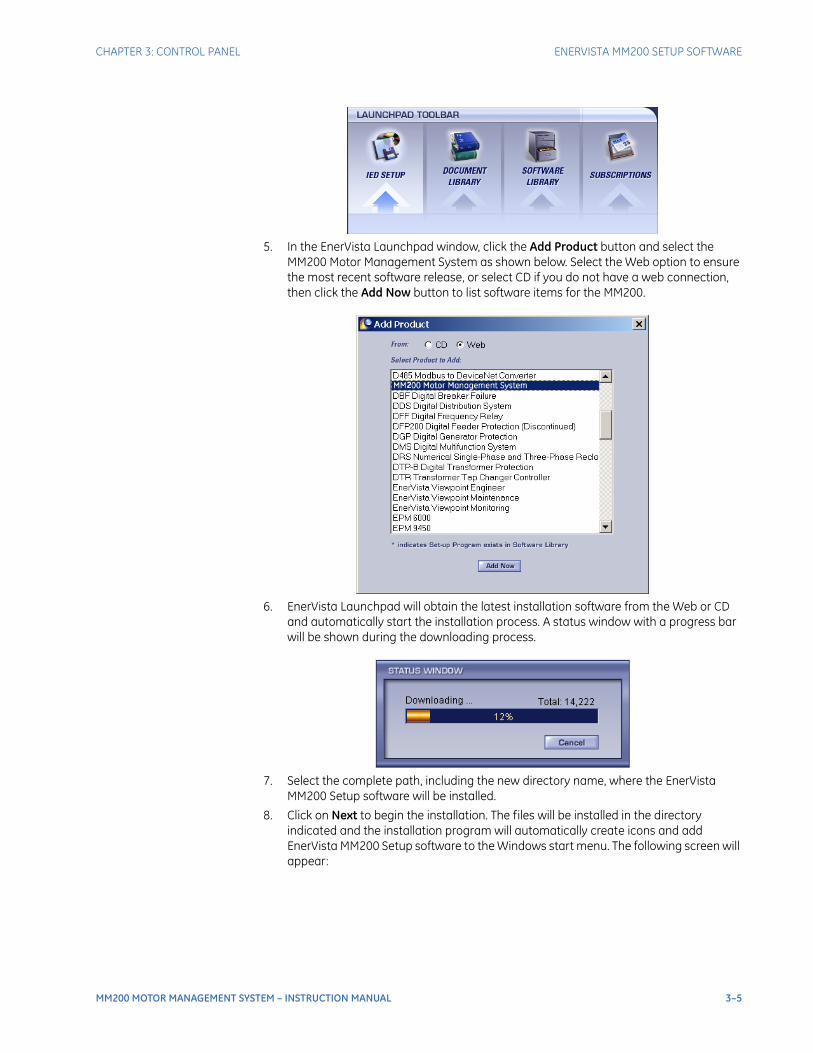
5. In the EnerVista Launchpad window, click the Add Product button and select the MM200 Motor Management System as shown below. Select the Web option to ensure the most recent software release, or select CD if you do not have a web connection, then click the Add Now button to list software items for the MM200.
6. EnerVista Launchpad will obtain the latest installation software from the Web or CD and automatically start the installation process. A status window with a progress bar will be shown during the downloading process.
7. Select the complete path, including the new directory name, where the EnerVista MM200 Setup software will be installed.
8. Click on Next to begin the installation. The files will be installed in the directory indicated and the installation program will automatically create icons and add EnerVista MM200 Setup software to the Windows start menu. The following screen will appear:
3–6 MM200 MOTOR MANAGEMENT SYSTEM – INSTRUCTION MANUAL
ENERVISTA MM200 SETUP SOFTWARE CHAPTER 3: CONTROL PANEL
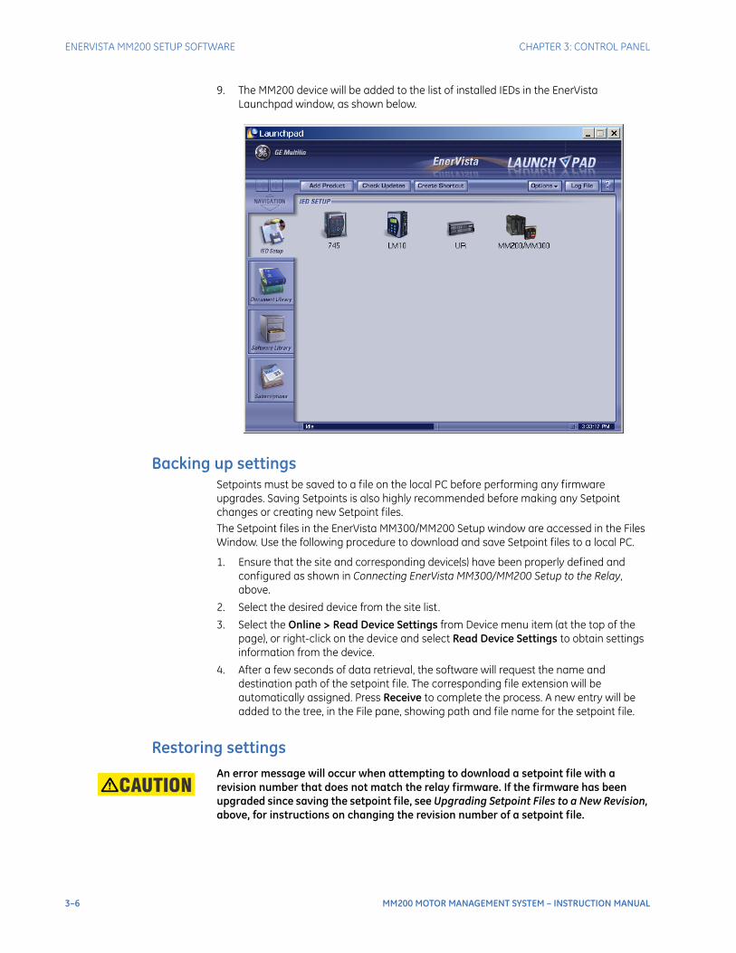
9. The MM200 device will be added to the list of installed IEDs in the EnerVista Launchpad window, as shown below.
Backing up settingsSetpoints must be saved to a file on the local PC before performing any firmware upgrades. Saving Setpoints is also highly recommended before making any Setpoint changes or creating new Setpoint files.The Setpoint files in the EnerVista MM300/MM200 Setup window are accessed in the Files Window. Use the following procedure to download and save Setpoint files to a local PC.
1. Ensure that the site and corresponding device(s) have been properly defined and configured as shown in Connecting EnerVista MM300/MM200 Setup to the Relay, above.
2. Select the desired device from the site list.
3. Select the Online > Read Device Settings from Device menu item (at the top of the page), or right-click on the device and select Read Device Settings to obtain settings information from the device.
4. After a few seconds of data retrieval, the software will request the name and destination path of the setpoint file. The corresponding file extension will be automatically assigned. Press Receive to complete the process. A new entry will be added to the tree, in the File pane, showing path and file name for the setpoint file.
Restoring settingsCAUTION: An error message will occur when attempting to download a setpoint file with a
revision number that does not match the relay firmware. If the firmware has been upgraded since saving the setpoint file, see Upgrading Setpoint Files to a New Revision, above, for instructions on changing the revision number of a setpoint file.
CHAPTER 3: CONTROL PANEL ENERVISTA MM200 SETUP SOFTWARE
MM200 MOTOR MANAGEMENT SYSTEM – INSTRUCTION MANUAL 3–7
The following procedure illustrates how to load setpoints from a file. Before loading a setpoints file, it must first be added to the EnerVista MM300/MM200 Setup environment as described in the section, Adding Setpoints Files to the Environment.
1. Select the previously saved setpoints file from the File pane of the software main window.
2. Select the Offline > Edit Settings File Properties menu item and verify that the corresponding file is fully compatible with the hardware and firmware version of the target relay. If the versions are not identical, see Upgrading Setpoint Files to a New Revision, above, for details on changing the setpoints file version.
3. Right-click on the selected file and select the Write Settings File to Device item.
4. Select the target relay from the list of devices shown and click Send. If there is an incompatibility, an "Incompatible Device" error message will occur:
If there are no incompatibilities between the target device and the settings file, the data will be transferred to the relay. An indication of the percentage completed will be shown at the bottom of the main window.
Upgrading firmwareTo upgrade the MM200 firmware, follow the procedures listed in this section. Upon successful completion of this procedure, the MM200 will have new firmware installed with the factory default setpoints.The latest firmware files are available from the GE Multilin website at http://www.gegridsolutions.com.
NOTE
NOTE: Upgrading firmware requires a RS232 to RJ45 custom cable (p/n 0804-0180), available at the GE Online Store (http://www.gegridsolutions.com). If your PC does not have an RS232 port, you will also need a USB-to-serial converter cable (p/n 0100-0001).
NOTE
NOTE: EnerVista MM300/MM200 Setup software prevents incompatible firmware from being loaded into an MM200 relay.
NOTE
NOTE: Before upgrading firmware, it is very important to save the current settings to a file on your PC. After the firmware has been upgraded, it will be necessary to load this file back into the MM200 relay. Refer to Backing up settings for details on saving relay setpoints to a file.
Use the following steps to upload the MM200 firmware to the MM200 device:
1. Remove the Basic Front Panel (if connected) from the BCP (RJ45) port of the CPU.
2. Connect the special RJ45 to DB9 cable through this RJ45 port to the computer's serial port. If needed, contact GE Multilin to place an order for this cable (p/n 0804-0180).
If your PC does not have an RS232 port, you will also need a USB-to-serial converter cable (p/n 0100-0001).
3. Launch the EnerVista MM300/MM200 Setup software application.
4. Open Device Setup and add a site and a device.
5. Select Serial as the interface.
Baud Rate = 115200
Slave Address = 254
Parity = None
Bits = 8
Stop Bits = 1
6. Select the COM Port number of the PC, to which the DB9 is connected (normally 1 or 2), and press the Read Order Code button.
7. Once the Order Code and Version are read from the device, press OK.

3–8 MM200 MOTOR MANAGEMENT SYSTEM – INSTRUCTION MANUAL
ENERVISTA MM200 SETUP SOFTWARE CHAPTER 3: CONTROL PANEL
8. In Setup Software, go to the Online window and expand the tree for this newly-added device.
9. Go to Maintenance > Firmware Upload, select the firmware file to be uploaded to the device, and press Proceed.
A popup message will appear, showing the type of cable connection needed to perform the firmware upload process (RJ45 to RS232 cable). When uploading firmware, remove the RS485 connector from the device.
When the warning message appears, press OK and the firmware will start to upload.
10. Once the Setup Software message appears indicating that the Firmware Upload was successful, reboot the device.
You have successfully uploaded the new firmware to the device, and the device is now ready to be used.After successfully updating the firmware, the relay will not be operational and will require setpoint programming. To communicate with the relay, the communication settings may have to be manually reprogrammed.When communications are established, the saved setpoints must be reloaded back into the relay. See Restoring settings for details.Modbus addresses assigned to firmware modules, features, settings, and corresponding data items (i.e. default values, min/max values, data type, and item size) may change slightly from version to version of the firmware. Addresses are rearranged when new features are added or existing features are enhanced or modified
Upgrading the softwareThe latest EnerVista software and firmware can be downloaded from:https://www.gegridsolutions.com/app/ViewFiles.aspx?prod=mm200&type=7After upgrading, check the version number under Help > About. If the new version does not display, try uninstalling the software and reinstalling the new versions.
Uninstalling files and clearing dataThe unit can be decommissioned by turning off the power to the unit and disconnecting the wires to it . Files can be cleared after uninstalling the EnerVista software or MM200 device, for example to comply with data security regulations.On the computer, settings files can be identified by the .m30 extension.To clear the current settings file do the following:
1. Create a default settings file.
2. Write the default settings file to the relay.
3. Delete all other files with the .m30 extension.
4. Delete any other data files, which can be in standard formats, such as COMTRADE or .csv.
You cannot directly erase the flash memory, but all records and settings in that memory can be deleted. Do this using these commands:DIAGNOSTICS > COMMANDS
• CLEAR LAST TRIP DATA PROMPT
• CLEAR TRIP COUNTERS
• CLEAR MAINTENANCE TIMER
• RESET MOTOR INFORMATION
MM200 MOTOR MANAGEMENT SYSTEM – INSTRUCTION MANUAL 4–1
MM200 Motor Management System
Chapter 4: Setpoints
GEGrid Solutions
Setpoints
Understanding setpoints
Setpoints can be modified via RS485, using the EnerVista MM200 Setup program.CAUTION: Setpoints may be changed while the motor is running; however it is not recommended
to change important protection parameters without first stopping the motor.
Setpoints will remain stored indefinitely in the internal non-volatile memory even when control power to the unit is removed. Protection parameters are based on the entered data. This data must be complete and accurate for the given system for reliable protection and operation of the motor.
Setting text abbreviationsThe following abbreviations are used in the setpoints pages.
• A, Amps: amperes
• AUX: auxiliary
• CBCT: core balance current transformer
• COM, Comms: communications
• CT: current transformer
• FLA: full load amps
• FV: full voltage
• G/F: ground fault
• GND: ground
• Hz: Hertz
• kohms: kilo-ohms
• MAX: maximum
• MIN: minimum
• SEC, s: seconds
• VT: voltage transformer

4–2 MM200 MOTOR MANAGEMENT SYSTEM – INSTRUCTION MANUAL
CONFIGURATION SETPOINTS CHAPTER 4: SETPOINTS
• %UB: percent unbalance
• Ctrl: control
• Hr & hr: hour
• O/L: overload
• ops: operations
• mcc: motor control center
Configuration setpoints
The configuration setpoints contains data on motor configuration as well as system setup, inputs, outputs, communications, and CTs.
• Motor (setpoints related to motor configuration).
• CT (setpoints related to CT configuration).
• Inputs (setpoints related to digital input configuration)
• Outputs (setpoints related to digital output configuration)
• Comms (setpoints related to communications configuration)
• System (setpoints related to MM200 system configuration, such as the faceplate LEDs)
• Counters (setpoints related to the digital counters)
Motor setpointsThe MM200 starter function is responsible for executing the motor startup sequence, including the pre-contactor start warning. The MM200 provides three pre-defined starters.
• Full-voltage non-reversing
• Full-voltage reversing
• Two-speed
NOTE
NOTE: By selecting a pre-defined starter, inputs and outputs are automatically assigned.
Common motorsetpoints
Several motor setpoints are dependent on the chosen starter type. The setpoints shown below are common to all starter types.
Motor NameRange: up to 20 alphanumeric charactersDefault: Motor Name
This setpoint specifies a name for the motor. This name will appear in the actual values.
Starter Type (Mandatory setpoint)Range: None, FV Non-Reversing, FV Reversing, Two SpeedDefault: FV Non-Reversing
This setpoint selects the starter type. The relay is essentially disabled when the value is set to “None”. Figure 1 illustrates typical starter timing beginning from the stopped state for all starter types.
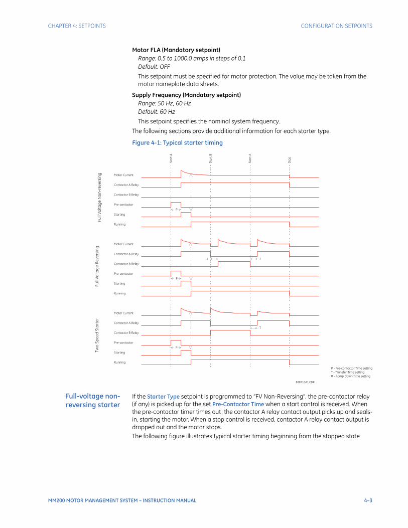
CHAPTER 4: SETPOINTS CONFIGURATION SETPOINTS
MM200 MOTOR MANAGEMENT SYSTEM – INSTRUCTION MANUAL 4–3
Motor FLA (Mandatory setpoint)Range: 0.5 to 1000.0 amps in steps of 0.1Default: OFF
This setpoint must be specified for motor protection. The value may be taken from the motor nameplate data sheets.
Supply Frequency (Mandatory setpoint)Range: 50 Hz, 60 HzDefault: 60 Hz
This setpoint specifies the nominal system frequency.
The following sections provide additional information for each starter type.
Figure 4-1: Typical starter timing
Full-voltage non-reversing starter
If the Starter Type setpoint is programmed to “FV Non-Reversing”, the pre-contactor relay (if any) is picked up for the set Pre-Contactor Time when a start control is received. When the pre-contactor timer times out, the contactor A relay contact output picks up and seals-in, starting the motor. When a stop control is received, contactor A relay contact output is dropped out and the motor stops.The following figure illustrates typical starter timing beginning from the stopped state.
Contactor B Relay
Contactor A Relay
Pre-contactor
Starting
Running
Sta
rtA
Sta
rtB
Sta
rtA
Sto
p
Motor Current
Fu
llV
olt
ag
eN
on
-re
ve
rsin
g
Contactor B Relay
Contactor A Relay
Pre-contactor
Starting
Running
Motor Current
Fu
llV
olt
ag
eR
ev
ers
ing
Contactor B Relay
Contactor A Relay
Pre-contactor
Starting
Running
Motor Current
Tw
oS
pe
ed
Sta
rte
r
P
T
P
P
T
T
P - Pre-contactor Time setting
T - Transfer Time setting
R - Ramp Down Time setting
888710A1.CDR
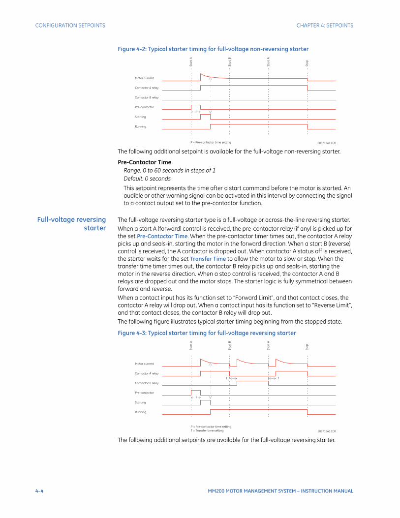
4–4 MM200 MOTOR MANAGEMENT SYSTEM – INSTRUCTION MANUAL
CONFIGURATION SETPOINTS CHAPTER 4: SETPOINTS
Figure 4-2: Typical starter timing for full-voltage non-reversing starter
The following additional setpoint is available for the full-voltage non-reversing starter.
Pre-Contactor TimeRange: 0 to 60 seconds in steps of 1Default: 0 seconds
This setpoint represents the time after a start command before the motor is started. An audible or other warning signal can be activated in this interval by connecting the signal to a contact output set to the pre-contactor function.
Full-voltage reversingstarter
The full-voltage reversing starter type is a full-voltage or across-the-line reversing starter.When a start A (forward) control is received, the pre-contactor relay (if any) is picked up for the set Pre-Contactor Time. When the pre-contactor timer times out, the contactor A relay picks up and seals-in, starting the motor in the forward direction. When a start B (reverse) control is received, the A contactor is dropped out. When contactor A status off is received, the starter waits for the set Transfer Time to allow the motor to slow or stop. When the transfer time timer times out, the contactor B relay picks up and seals-in, starting the motor in the reverse direction. When a stop control is received, the contactor A and B relays are dropped out and the motor stops. The starter logic is fully symmetrical between forward and reverse.When a contact input has its function set to “Forward Limit”, and that contact closes, the contactor A relay will drop out. When a contact input has its function set to “Reverse Limit”, and that contact closes, the contactor B relay will drop out.The following figure illustrates typical starter timing beginning from the stopped state.
Figure 4-3: Typical starter timing for full-voltage reversing starter
The following additional setpoints are available for the full-voltage reversing starter.
Contactor B relay
Contactor A relay
Pre-contactor
Starting
Running
Sta
rtA
Sta
rtB
Sta
rtA
Sto
p
Motor current
P
P = Pre-contactor time setting 888717A1.CDR
Sta
rtA
Sta
rtB
Sta
rtA
Sto
p
Contactor B relay
Contactor A relay
Pre-contactor
Starting
Running
Motor current
T
P
T
P = Pre-contactor time setting
T = Transfer time setting 888718A1.CDR
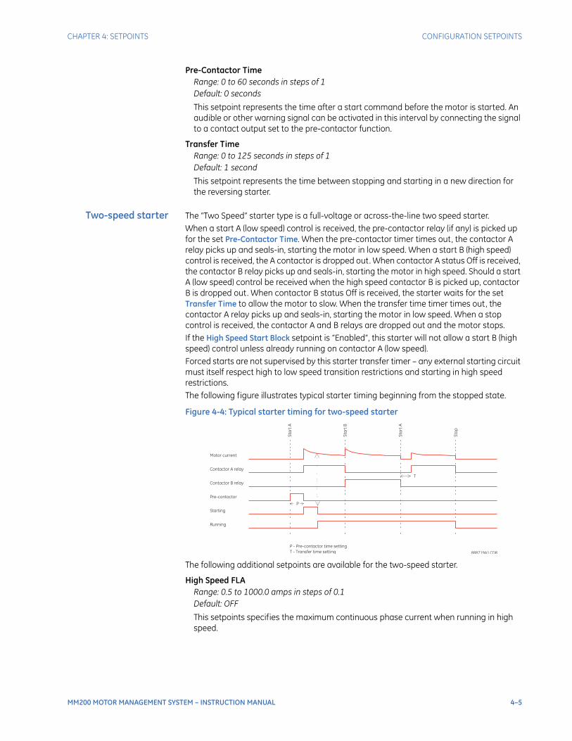
CHAPTER 4: SETPOINTS CONFIGURATION SETPOINTS
MM200 MOTOR MANAGEMENT SYSTEM – INSTRUCTION MANUAL 4–5
Pre-Contactor TimeRange: 0 to 60 seconds in steps of 1Default: 0 seconds
This setpoint represents the time after a start command before the motor is started. An audible or other warning signal can be activated in this interval by connecting the signal to a contact output set to the pre-contactor function.
Transfer TimeRange: 0 to 125 seconds in steps of 1Default: 1 second
This setpoint represents the time between stopping and starting in a new direction for the reversing starter.
Two-speed starter The “Two Speed” starter type is a full-voltage or across-the-line two speed starter.When a start A (low speed) control is received, the pre-contactor relay (if any) is picked up for the set Pre-Contactor Time. When the pre-contactor timer times out, the contactor A relay picks up and seals-in, starting the motor in low speed. When a start B (high speed) control is received, the A contactor is dropped out. When contactor A status Off is received, the contactor B relay picks up and seals-in, starting the motor in high speed. Should a start A (low speed) control be received when the high speed contactor B is picked up, contactor B is dropped out. When contactor B status Off is received, the starter waits for the set Transfer Time to allow the motor to slow. When the transfer time timer times out, the contactor A relay picks up and seals-in, starting the motor in low speed. When a stop control is received, the contactor A and B relays are dropped out and the motor stops.If the High Speed Start Block setpoint is “Enabled”, this starter will not allow a start B (high speed) control unless already running on contactor A (low speed).Forced starts are not supervised by this starter transfer timer – any external starting circuit must itself respect high to low speed transition restrictions and starting in high speed restrictions.The following figure illustrates typical starter timing beginning from the stopped state.
Figure 4-4: Typical starter timing for two-speed starter
The following additional setpoints are available for the two-speed starter.
High Speed FLARange: 0.5 to 1000.0 amps in steps of 0.1Default: OFF
This setpoints specifies the maximum continuous phase current when running in high speed.
Sta
rtA
Sta
rtB
Sta
rtA
Sto
p
Contactor B relay
Contactor A relay
Pre-contactor
Starting
Running
Motor current
P
T
P - Pre-contactor time setting
T - Transfer time setting 888719A1.CDR
4–6 MM200 MOTOR MANAGEMENT SYSTEM – INSTRUCTION MANUAL
CONFIGURATION SETPOINTS CHAPTER 4: SETPOINTS
Pre-Contactor TimeRange: 0 to 60 seconds in steps of 1Default: 0 seconds
This setpoint represents the time between a start command and the starting of the motor. An audible or other warning signal can be activated during this interval, by connecting the signal to a contact output set to the pre-contactor function.
High Speed Start BlockRange: Enabled, DisabledDefault: Enabled
This setpoint specifies the high-speed motor rating for two-speed starters, in kW on the line. This setpoint is for reference only, and does not affect operation of the MM200.
Transfer TimeRange: 0 to 125 seconds in steps of 1Default: 1 second
This setpoint represents the time between running at high speed and starting at low speed for the two speed starter.
Current transformersThe following setpoints are available to configure the current and voltage transformers.
Phase CT Type (Mandatory setpoint)Range: None, 1 A Secondary, 5 A Secondary, Direct ConnectDefault: Direct Connect
This setpoint specifies the phase CT connection type. The “Direct Connect” value indicates that no phase CTs are used; instead, motor phase current passes directly through the relay. The “Direct Connect” selection should never be used where full load current is greater than 5.0 amps.
NOTE
NOTE: If Direct Connect is selected and the FLA is set >5 A, a "FLA too high" message will be displayed on the Status page.
CT Primary TurnsRange: 1 to 10Default: 1
For smaller motors where the drawn current is very low, the motor leads may be wrapped through the CT Primary with several turns thereby increasing the current seen by the MM200 and as a result increasing the accuracy of the measurement. The value of this setting should equal the number of turns on the CT Primary to display the correct current value. Internally the current measurement will be divided by this setting.
CT Primary (Mandatory setpoint)Range: 5 to 1000 amps in steps of 1Default: 5 amps
This setpoint specifies the phase CT primary current. It should never be less than the full load current, and preferably no greater than twice than the full load current.
NOTE
NOTE: This setpoint is displayed only if the phase CT is selected to 1 A secondary or 5 A secondary.

CHAPTER 4: SETPOINTS CONFIGURATION SETPOINTS
MM200 MOTOR MANAGEMENT SYSTEM – INSTRUCTION MANUAL 4–7
High Speed CT PrimaryRange: 5 to 1000 amps in steps of 1Default: 5 amps
This setpoint specifies the phase CT primary current when the motor is running at high speed. It should never be less than the high speed full load current, and preferably no greater than twice than the high speed full load current.
NOTE
NOTE: This setpoint is displayed only if the phase CT is selected as 1 A secondary or 5 A secondary and the motor starter type is two-speed.
InputsThe MM200 digital (contact) inputs are programmed in this menu.
NOTE
NOTE: Inputs are automatically assigned based on typical wiring diagrams, shown in chapter 2, when a pre-defined starter is selected.
The following setpoints are available for each contact input:
FunctionRange: Access Switch, Comms Permissive, Contactor A Status, Contactor B Status, Field Permissive, Field Start A, Field Start B, Field Stop, Forward Limit, Hard Wired Permissive, Hard Wired Start A, Hard Wired Start B, Hard Wired Stop, Lockout Reset, MCC Permissive, Remote Reset, Reverse Limit, Test Switch, Auto/Manual Switch, Poaer Failure Restart Inhibit, Power Failure Input.Default: None
– “Access Switch”: This value represents an open contact that disables security access of selected levels. When closed, sets the access level to the value configured in Security > Access Switch Level.
– “Auto/Manual”: "Close" sets the auto mode. "Open" sets the manual mode.
– “Comms Permissive”: This value represents an open contact that disables communications control. Used by the auto/manual control element.
– “Contactor A Status”: This value represents the normally open auxiliary contact of contactor A. Used by the starters, the stop/start control element, and the system trouble function. Automatically assigned to the first input when a starter type is selected. Not otherwise user-programmable.
– “Contactor B Status”: This value represents the normally open auxiliary contact of contactor B. Used by the starters, the stop/start control element, and the system trouble function. Automatically assigned to the second input when a reversing or two-speed starter type is selected. Not otherwise user assignable.
– “Field Permissive”: This value represents an open contact which disables field control. Used by the auto/manual control element.
– “Field Start A”: This value represents a field-located manual switch requesting contactor A pickup. Used by the auto/manual control element.
– “Field Start B”: This value represents a field-located manual switch requesting contactor B pickup. Used by the auto/manual control element.
– “Field Stop”: This value represents a field-located manual switch where an open position requests stop. Used by the auto/manual control element.
– “Forward Limit”: This value represents a contact which opens at the forward travel limit. Used by the reversing starter type.
– “Hard Wired Permissive”: This value represents an open contact that disables hard-wired control. Used by the auto/manual control element.
4–8 MM200 MOTOR MANAGEMENT SYSTEM – INSTRUCTION MANUAL
CONFIGURATION SETPOINTS CHAPTER 4: SETPOINTS
– “Hard Wired Start A”: This value represents an auto contact (typically from a PLC) requesting contactor A pickup. Used by the auto/manual control element.
– “Hard Wired Start B”: This value represents an auto contact (typically from a PLC) requesting contactor B pickup. Used by the auto/manual control element.
– “Hard Wired Stop”: This value represents an auto contact (typically from a PLC) where the open position requests stop. Used by the auto/manual control element.
– “Lockout Reset”: This value represents a contact input used to reset lockouts, trips, and alarms.
– “NA”: This value indicates the contact Input has no assigned function.
– “MCC Permissive”: This value represents an open contact that disables MCC control. Used by the auto/manual control element.
– “Remote Reset”: This value represents a contact input used to resets non-lockout trips and alarms.
– “Reverse Limit”: This value represents a contact which opens at the reverse travel limit. Used by the reversing starter type.
– “Test Switch”: This value represents a contact input used to suspend collection of selected data items, override auto/manual modes, and cause interlocks to be ignored.
– “Power Failure Input”: This value represents a contact input used to detect an undervoltage which is detected by a digital input associated externally with an External Voltage Relay and then starts the Power Failure Restart function.
– “Power Failure Restart Inhibit Input”: This value represents a contact input used to inhibit the Power Failure Restart function.
NOTE
NOTE: When a Lockout Reset is used to reset a Thermal Overload, the Thermal Capacity % will be reset to zero.
OutputsContact outputs are designated by their card slot letter appended with their card terminal number. Contact outputs, which have two or three terminals, use the first of their terminal numbers on the GCP. This is the same scheme as is used to form the relay terminal designation.When a starter type is selected, the first equipped contact output and the first equipped contact input are forced to the contactor A relay function and the contactor A status function, respectively. When the two-speed or reversing starter type is selected, the second equipped contact output and the second equipped contact input are forced to the contactor B relay function and the contactor B status function, respectively. Any prior values for these setpoints are erased, and the setpoint becomes non-editable.
Communications setpointsThe MM200 has one RS485 serial communications port supporting a subset of the Modbus protocol. An additional DeviceNet or Profibus port is also available as an option.The following setpoints are available.
Slave AddressRange: 1 to 254 in steps of 1Default: 254
For RS485 communications, each MM200 IED must have a unique address from 1 to 254. Address 0 is the broadcast address detected by all IEDs in the serial link. Addresses do not have to be sequential, but no two units can have the same address or errors will occur. Generally, each unit added to the link uses the next higher address starting at 1.
CHAPTER 4: SETPOINTS CONFIGURATION SETPOINTS
MM200 MOTOR MANAGEMENT SYSTEM – INSTRUCTION MANUAL 4–9
RS485 Baud RateRange: 9600, 19200, 38400, 57600, or 115200 baudDefault: 115200 baud
This setpoint selects the baud rate for the RS485 port. The data frame is fixed at 1 start, 8 data, and 1 stop bits, while parity is optional.
DeviceNet MAC IDRange: 0 to 63 in steps of 1Default: 63
This setpoint specifies the dedicated MAC ID as per the DeviceNet design.
DeviceNet Baud RateRange: 125, 250, or 500 kbpsDefault: 125 kbps
This setpoint selects the DeviceNet baud rate.
Profibus AddressRange: 1 to 125Default: 1
This setpoint allows the user to select the appropriate Profibus address.
Profibus Baud RateRange: 9600 to 1.5 MDefault: 1.5 M
This setpoint selects the Profibus baud rate.
Comms OK EvaluationRange: Serial, Serial + Fieldbus, Fieldbus, AllDefault: Serial
Specifies the operands for the Comms OK flag.
Comm Failure TripRange: Off, 1 to 29 step 1sDefault: Off
Specifies the time without comms before a trip will be generated.
Comm Failure AlarmRange: Off, 1 to 29 step 1sDefault: Off
Specifies the time without comms before an alarm will be generated.
NOTE
NOTE: Timing delay commences after failure is detected.
Change Mode on Comm AlarmRange: Disabled, EnabledDefault: Disabled
If enabled, forces control mode to manual if comms are lost.
System
System security Hardware and passcode security features are designed to restrict user access. This can deter inappropriate employee action and curtail errors. Security against hackers or others with malicious intent should be provided by other means. Security for the external hard-wired and field controls should also be externally provided as required.
4–10 MM200 MOTOR MANAGEMENT SYSTEM – INSTRUCTION MANUAL
CONFIGURATION SETPOINTS CHAPTER 4: SETPOINTS
Three security levels above the default level are recognized. Each security level can also be set for passcode access. The passcode is programmed as a five-digit number, using only digits 1 through 5. The security access levels are:
• Default - start/stop control, auto/manual selection, and reset trips
• Level 1 - default privileges plus setpoint access
• Level 2 - level 1 privileges plus lockout reset and reset counters
• Level 3 - level 2 privileges plus factory page.
Passcodes are automatically canceled after five minutes of inactivity. Communications passcode access can be cancelled by writing zero to the passcode register.The following system security setpoints are programmed in the security page.
Passcode Level 1, Passcode Level 2, Passcode Level 3Range: any five-digit number using digits 1 through 5 only or DisabledDefault value: 11111 (level 1), 22222 (level 2)
Access is granted if a passcode has been correctly entered matching the value of this setpoint.
Access Switch LevelRange: 1, 2, 3Default value: 1
Sets the access level provided by the access switch being closed. The contact input for the access switch is configured on the contact inputs page.
Comms securityRange: Enabled, DisabledDefault: Disabled
Sets whether the security feature applies to the communications ports.
System trouble For relay self-test, the MM200 runs a series of self-tests, including data and program memory integrity and program execution watchdogs. If any of these tests fail, a self-test trip or alarm is generated depending on the value of the Self Test Action setpoint.The following setpoints are available for the system trouble element.
Self-Test ActionRange: Trip, AlarmDefault: Trip
This setpoint defines whether a self-test failure will cause a trip or an alarm.
LED indicators These setpoints allow the user to control the display characteristics of the front panel LEDs.The following setpoints are available.
User 1 LED Assignment, User 2 LED Assignment, User 3 LED AssignmentRange: Any alarm trip control I/O operandDefault: Not Set
This setpoint determines whether the Tripped LED flashes or is steadily illuminated when there is a trip or lockout condition.
USER 1 LED ColorRange: None, Red, Green, OrangeDefault: Red
Selects the color of the USER LEDs.
CHAPTER 4: SETPOINTS CONFIGURATION SETPOINTS
MM200 MOTOR MANAGEMENT SYSTEM – INSTRUCTION MANUAL 4–11
USER 2 LED ColorRange: None, Red, Green, OrangeDefault: Red
Selects the color of the USER LEDs.
Reset Lockout using Reset KeyRange: Disabled, EnabledDefault: Disabled
When this setpoint is programmed as "Disabled," the relay does not allow performing of the Reset Lockout using the Reset key. When programmed as "Enabled," the Reset Lockout can be performed using the Reset key.
Change Mode when RunningRange: Disabled, EnabledDefault: Disabled
When this setpoint is programmed as "Disabled," the relay does not allow changing of the Auto/Manual mode. When programmed as "Enabled," the relay does allow changing of the Auto/Manual mode.
Running LED ColorRange: None, Red, Green, OrangeDefault: Green
Selects the color of the Running LED.
Stopped LED ColorRange: None, Red, Green, OrangeDefault: Red
Selects the color of the Stopped LED.
Alarm LED ColorRange: None, Red, Green, OrangeDefault: Orange
Selects the color of the Alarm LED.
Tripped LED ColorRange: None, Red, Green, OrangeDefault: Red
Selects the color of the Tripped LED.
Comms OK LED ColorRange: None, Red, Green, OrangeDefault: Green
Selects the color of the Comms OK LED.
Auto LED ColorRange: None, Red, Green, OrangeDefault: Orange
Selects the color of the Auto LED.
Manual LED ColorRange: None, Red, Green, OrangeDefault: Orange
Selects the color of the Manual LED.

4–12 MM200 MOTOR MANAGEMENT SYSTEM – INSTRUCTION MANUAL
PROTECTION ELEMENTS CHAPTER 4: SETPOINTS
50% LED ColorRange: None, Red, Green, OrangeDefault: Orange
Selects the LED color at 50% of the motor load.
80% LED ColorRange: None, Red, Green, OrangeDefault: Orange
Selects the LED color at 80% of the motor load.
100% LED ColorRange: None, Red, Green, OrangeDefault: Orange
Selects the LED color at 100% of the motor load.
Counters Settings Drive Greasing IntervalRange: 100 to 50000 hours in steps of 100 hoursDefault: OFF
This setpoint allows the user to set the alarm level for the greasing interval
Contactor Inspection IntervalRange: 0 to 64000 hours in steps of 100 hoursDefault: OFF
This setpoint allows the user to set the alarm level for the contactor inspection interval.
Maximum Motor Stopped TimeRange: 10 to 10000 hours in steps of 10 hoursDefault: OFF
This setpoint allow the user to set the alarm level for the maximum allowable motor stopped hours.
Protection elements
Thermal protectionThe primary protective function of the MM200 is the thermal model. The MM200 integrates stator and rotor heating into a single model. The rate of motor heating is gauged by measuring the terminal currents. The present value of the accumulated motor heating is maintained in the Thermal Capacity Used actual value register. When the motor is in overload, the motor temperature and thermal capacity used will rise. A trip occurs when the thermal capacity used reaches 100%. When the motor is stopped and is cooling to ambient, the thermal capacity used decays to zero. If the motor is running normally, the motor temperature will eventually stabilize at some steady state temperature, and the thermal capacity used increases or decreases to some corresponding intermediate value, which accounts for the reduced amount of thermal capacity left to accommodate transient overloads.The thermal model consists of four key elements.
• Hot/cold biasing that accounts for normal temperature rise.
• An overload curve that accounts for the rapid heating that occurs during stall, acceleration, and overload.
• Cooling rate that accounts for heat dissipation.
• Thermal protection reset that controls recovery from thermal trips and lockouts.
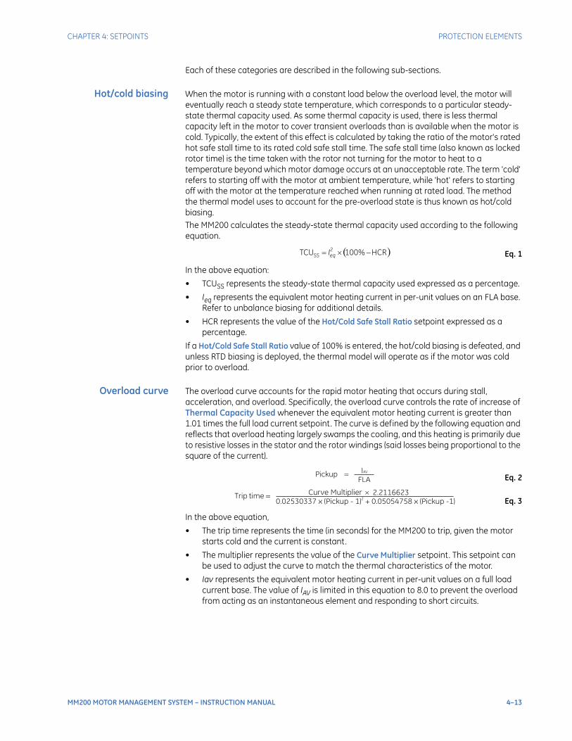
CHAPTER 4: SETPOINTS PROTECTION ELEMENTS
MM200 MOTOR MANAGEMENT SYSTEM – INSTRUCTION MANUAL 4–13
Each of these categories are described in the following sub-sections.
Hot/cold biasing When the motor is running with a constant load below the overload level, the motor will eventually reach a steady state temperature, which corresponds to a particular steady-state thermal capacity used. As some thermal capacity is used, there is less thermal capacity left in the motor to cover transient overloads than is available when the motor is cold. Typically, the extent of this effect is calculated by taking the ratio of the motor's rated hot safe stall time to its rated cold safe stall time. The safe stall time (also known as locked rotor time) is the time taken with the rotor not turning for the motor to heat to a temperature beyond which motor damage occurs at an unacceptable rate. The term 'cold' refers to starting off with the motor at ambient temperature, while 'hot' refers to starting off with the motor at the temperature reached when running at rated load. The method the thermal model uses to account for the pre-overload state is thus known as hot/cold biasing.The MM200 calculates the steady-state thermal capacity used according to the following equation.
Eq. 1
In the above equation:
• TCUSS represents the steady-state thermal capacity used expressed as a percentage.
• Ieq represents the equivalent motor heating current in per-unit values on an FLA base. Refer to unbalance biasing for additional details.
• HCR represents the value of the Hot/Cold Safe Stall Ratio setpoint expressed as a percentage.
If a Hot/Cold Safe Stall Ratio value of 100% is entered, the hot/cold biasing is defeated, and unless RTD biasing is deployed, the thermal model will operate as if the motor was cold prior to overload.
Overload curve The overload curve accounts for the rapid motor heating that occurs during stall, acceleration, and overload. Specifically, the overload curve controls the rate of increase of Thermal Capacity Used whenever the equivalent motor heating current is greater than 1.01 times the full load current setpoint. The curve is defined by the following equation and reflects that overload heating largely swamps the cooling, and this heating is primarily due to resistive losses in the stator and the rotor windings (said losses being proportional to the square of the current).
Eq. 2
Eq. 3
In the above equation,
• The trip time represents the time (in seconds) for the MM200 to trip, given the motor starts cold and the current is constant.
• The multiplier represents the value of the Curve Multiplier setpoint. This setpoint can be used to adjust the curve to match the thermal characteristics of the motor.
• Iav represents the equivalent motor heating current in per-unit values on a full load current base. The value of IAV is limited in this equation to 8.0 to prevent the overload from acting as an instantaneous element and responding to short circuits.
� �HCR%100TCU2
SS��� eqI
�
IAV
PickupFLA
�
�
Curve MultipliertimeTrip
2.2116623
0.02530337 x (Pickup - 1) + 0.05054758 x (Pickup -1)2

4–14 MM200 MOTOR MANAGEMENT SYSTEM – INSTRUCTION MANUAL
PROTECTION ELEMENTS CHAPTER 4: SETPOINTS
For example, a motor with a stall current (also known as locked rotor current) of 8 times its FLA, with a curve multiplier of 7, if stalled from a cold state, trips in the following amount of time.
Eq. 4
This would respect a safe stall cold time of 10 seconds.The standard overload curves are displayed below.
Figure 4-5: Standard overload curves
The trip times for the standard overload curves are tabulated below.
�
�
Curve MultipliertimeTrip
2.2116623
0.02530337 x (Pickup - 1) + 0.05054758 x (Pickup -1)2
�
�
7 2.2116623
0.02530337 x (8 - 1) + 0.05054758 x (8 -1)2
� 9.714 seconds
x1
x15
100000
10000
1000
100
10
1.00
0.10 1.00
MULTIPLE OF FULL LOAD AMPS
TIM
EIN
SE
CO
ND
S
10 100 1000
888731A2.CDR

CHAPTER 4: SETPOINTS PROTECTION ELEMENTS
MM200 MOTOR MANAGEMENT SYSTEM – INSTRUCTION MANUAL 4–15
Table 4-1: Standard overload curve trip times (in seconds)
PICKUP (× FLA)
STANDARD CURVE MULTIPLIERS
× 1 × 2 × 3 × 4 × 5 × 6 × 7 × 8 × 9 × 10 × 11 × 12 × 13 × 14 × 15
1.01
4353.6
8707.2
13061
17414
21768
26122
30475
34829
39183
43536
47890
52243
56597
60951
65304
1.05
853.71
1707.4
2561.1
3414.9
4268.6
5122.3
5976.0
6829.7
7683.4
8537.1
9390.8
10245
11098
11952
12806
1.10
416.68
833.36
1250.0
1666.7
2083.4
2500.1
2916.8
3333.5
3750.1
4166.8
4583.5
5000.2
5416.9
5833.6
6250.2
1.20
198.86
397.72
596.58
795.44
994.30
1193.2
1392.0
1590.9
1789.7
1988.6
2187.5
2386.3
2585.2
2784.1
2982.9
1.30
126.80
253.61
380.41
507.22
634.02
760.82
887.63
1014.4
1141.2
1268.0
1394.8
1521.6
1648.5
1775.3
1902.1
1.40
91.14
182.27
273.41
364.55
455.68
546.82
637.96
729.09
820.23
911.37
1002.5
1093.6
1184.8
1275.9
1367.0
1.50
69.99
139.98
209.97
279.96
349.95
419.94
489.93
559.92
629.91
699.90
769.89
839.88
909.87
979.86
1049.9
1.75
42.41
84.83
127.24
169.66
212.07
254.49
296.90
339.32
381.73
424.15
466.56
508.98
551.39
593.81
636.22
2.00
29.16
58.32
87.47
116.63
145.79
174.95
204.11
233.26
262.42
291.58
320.74
349.90
379.05
408.21
437.37
2.25
21.53
43.06
64.59
86.12
107.65
129.18
150.72
172.25
193.78
215.31
236.84
258.37
279.90
301.43
322.96
2.50
16.66
33.32
49.98
66.64
83.30
99.96
116.62
133.28
149.94
166.60
183.26
199.92
216.58
233.24
249.90
2.75
13.33
26.65
39.98
53.31
66.64
79.96
93.29
106.62
119.95
133.27
146.60
159.93
173.25
186.58
199.91
3.00
10.93
21.86
32.80
43.73
54.66
65.59
76.52
87.46
98.39
109.32
120.25
131.19
142.12
153.05
163.98
3.25
9.15 18.29
27.44
36.58
45.73
54.87
64.02
73.16
82.31
91.46
100.60
109.75
118.89
128.04
137.18
3.50
7.77 15.55
23.32
31.09
38.87
46.64
54.41
62.19
69.96
77.73
85.51
93.28
101.05
108.83
116.60
3.75
6.69 13.39
20.08
26.78
33.47
40.17
46.86
53.56
60.25
66.95
73.64
80.34
87.03
93.73
100.42
4.00
5.83 11.66
17.49
23.32
29.15
34.98
40.81
46.64
52.47
58.30
64.13
69.96
75.79
81.62
87.45
4.25
5.12 10.25
15.37
20.50
25.62
30.75
35.87
41.00
46.12
51.25
56.37
61.50
66.62
71.75
76.87
4.50
4.54 9.08 13.63
18.17
22.71
27.25
31.80
36.34
40.88
45.42
49.97
54.51
59.05
63.59
68.14
4.75
4.06 8.11 12.17
16.22
20.28
24.33
28.39
32.44
36.50
40.55
44.61
48.66
52.72
56.77
60.83
5.00
3.64 7.29 10.93
14.57
18.22
21.86
25.50
29.15
32.79
36.43
40.08
43.72
47.36
51.01
54.65
5.50
2.99 5.98 8.97 11.96
14.95
17.94
20.93
23.91
26.90
29.89
32.88
35.87
38.86
41.85
44.84
6.00
2.50 5.00 7.49 9.99 12.49
14.99
17.49
19.99
22.48
24.98
27.48
29.98
32.48
34.97
37.47
6.50
2.12 4.24 6.36 8.48 10.60
12.72
14.84
16.96
19.08
21.20
23.32
25.44
27.55
29.67
31.79
7.00
1.82 3.64 5.46 7.29 9.11 10.93
12.75
14.57
16.39
18.21
20.04
21.86
23.68
25.50
27.32
7.50
1.58 3.16 4.75 6.33 7.91 9.49 11.08
12.66
14.24
15.82
17.41
18.99
20.57
22.15
23.74
8.00
1.39 2.78 4.16 5.55 6.94 8.33 9.71 11.10
12.49
13.88
15.27
16.65
18.04
19.43
20.82
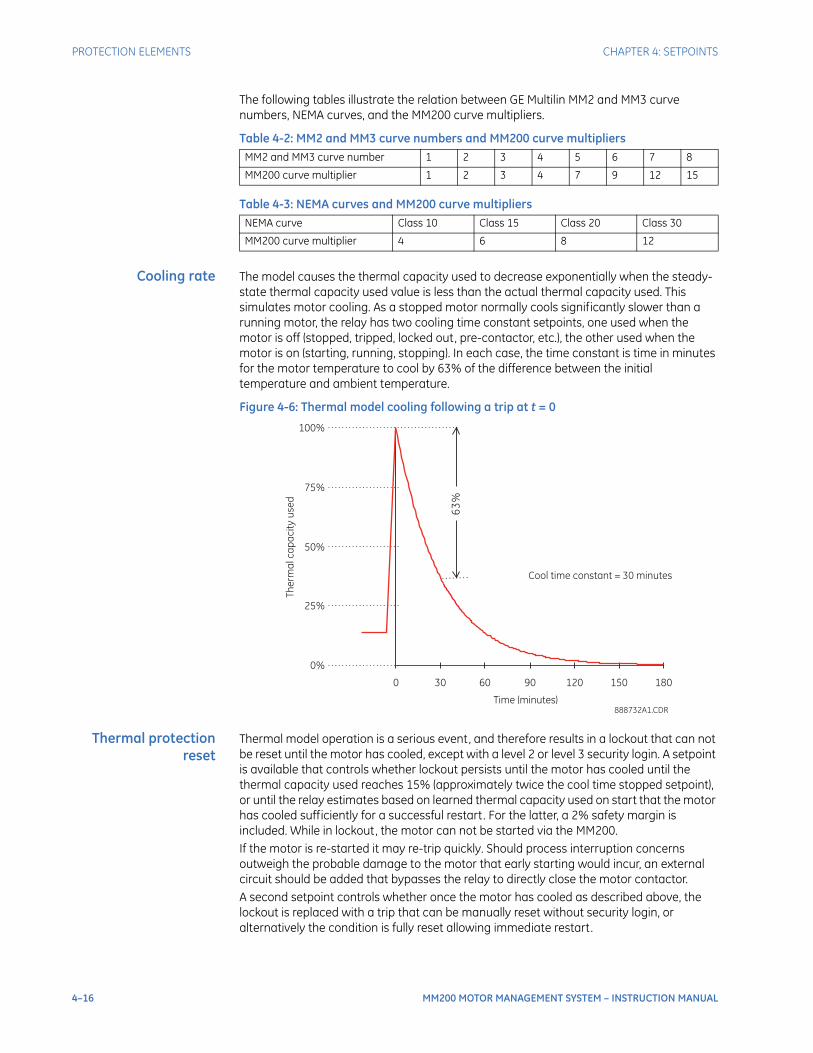
4–16 MM200 MOTOR MANAGEMENT SYSTEM – INSTRUCTION MANUAL
PROTECTION ELEMENTS CHAPTER 4: SETPOINTS
The following tables illustrate the relation between GE Multilin MM2 and MM3 curve numbers, NEMA curves, and the MM200 curve multipliers.
Table 4-2: MM2 and MM3 curve numbers and MM200 curve multipliers
Table 4-3: NEMA curves and MM200 curve multipliers
Cooling rate The model causes the thermal capacity used to decrease exponentially when the steady-state thermal capacity used value is less than the actual thermal capacity used. This simulates motor cooling. As a stopped motor normally cools significantly slower than a running motor, the relay has two cooling time constant setpoints, one used when the motor is off (stopped, tripped, locked out, pre-contactor, etc.), the other used when the motor is on (starting, running, stopping). In each case, the time constant is time in minutes for the motor temperature to cool by 63% of the difference between the initial temperature and ambient temperature.
Figure 4-6: Thermal model cooling following a trip at t = 0
Thermal protectionreset
Thermal model operation is a serious event, and therefore results in a lockout that can not be reset until the motor has cooled, except with a level 2 or level 3 security login. A setpoint is available that controls whether lockout persists until the motor has cooled until the thermal capacity used reaches 15% (approximately twice the cool time stopped setpoint), or until the relay estimates based on learned thermal capacity used on start that the motor has cooled sufficiently for a successful restart. For the latter, a 2% safety margin is included. While in lockout, the motor can not be started via the MM200.If the motor is re-started it may re-trip quickly. Should process interruption concerns outweigh the probable damage to the motor that early starting would incur, an external circuit should be added that bypasses the relay to directly close the motor contactor.A second setpoint controls whether once the motor has cooled as described above, the lockout is replaced with a trip that can be manually reset without security login, or alternatively the condition is fully reset allowing immediate restart.
MM2 and MM3 curve number 1 2 3 4 5 6 7 8
MM200 curve multiplier 1 2 3 4 7 9 12 15
NEMA curve Class 10 Class 15 Class 20 Class 30
MM200 curve multiplier 4 6 8 12
0%
25%
50%
75%
100%
0 30 60 90 120 150 180
Time (minutes)
Cool time constant = 30 minutes
63
%
Th
erm
alc
ap
ac
ity
use
d
888732A1.CDR

CHAPTER 4: SETPOINTS PROTECTION ELEMENTS
MM200 MOTOR MANAGEMENT SYSTEM – INSTRUCTION MANUAL 4–17
Thermal protectionsetpoints
The following setpoints are available for thermal protection.
Standard Overload CurveRange: 1 to 15 in steps of 1Default: 4
This setpoint specifies the standard overload curve to the thermal characteristics of the protected motor.
Overload Pickup LevelRange: 1.01 to 1.25 X FLADefault: 4
This setpoint specifies the Overload Pickup Level for the unit to start.
Hot/Cold Safe Stall RatioRange: 1 to 100% in steps of 1Default: 75%
This setpoint is used to control the hot/cold bias and RTD bias features. It specifies the ratio of the rated hot safe stall time to the rated cold safe stall time as a percentage. A value of “100%” disables the hot/cold bias feature.
Cool Time Constant StoppedRange: 1 to 1000 minutes in steps of 1Default: 30 minutes
This setpoint specifies the cooling time constant used by the thermal model when the motor is stopped. Enter the time in minutes for the temperature to cool by 63% of the difference between the initial value and ambient when the motor is stationary.
Cool Time Constant RunningRange: 1 to 1000 minutes in steps of 1Default: 15 minutes
This setpoint specifies the cooling time constant used by the thermal model when the motor is running. Enter the time in minutes for the temperature to cool by 63% of the difference between the initial value and ambient when the motor is at speed.
Minimize Reset TimeRange: Enabled, DisabledDefault: Disabled
When set to “Disabled”, the lockout condition following a thermal protection operation will persist until the thermal capacity used has dropped to 15%. When set to “Enabled”, the lockout persists until the thermal capacity used has dropped to 2% below the learned thermal capacity used at start (refer to the Thermal Start Inhibit for details).
Overload Reset ModeRange: Manual, AutoDefault: Manual
If this setpoint value is “Auto”, an automatic reset of overload lockouts occurs after the motor has cooled as described above. When set to “Manual”, the lockouts are replaced with trips when the motor cools, the trips must be reset by the control panel, by remote contact or by communications before the motor can be restarted.
Mechanical protectionThe mechanical protection setpoints are divided into the following categories.
• Mechanical jam
• Undercurrent protection
• Acceleration protection
4–18 MM200 MOTOR MANAGEMENT SYSTEM – INSTRUCTION MANUAL
PROTECTION ELEMENTS CHAPTER 4: SETPOINTS
• Open control circuit trip.
The setpoints applicable to each of these categories are described in the following sections.
Mechanical jam After the motor has started and reached a running state, the mechanical jam element (if enabled) produces a trip when the magnitude of Ia, Ib, or Ic reaches or exceeds the pickup level for the time specified by the Mechanical Jam Delay setpoint. This feature may be used to indicate a stall condition when running. Not only does it protect the motor by taking it off-line faster than the thermal model (overload curve), it may also prevent or limit damage to the driven equipment if motor starting torque persists on jammed or broken equipment.The Mechanical Jam Level should be set higher than motor loading during normal operation, but lower than the motor stall level. Normally the delay is set to the minimum time delay or to avoid nuisance trips due to momentary load fluctuations.The following setpoints are available for the mechanical jam element.
Mechanical Jam LevelRange: 1.01 to 4.50 × FLA in steps of 0.01 or OFFDefault: OFF
This setpoint specifies the current pickup level. Set this value to “OFF” to disable mechanical jam protection.
Mechanical Jam DelayRange: 0.1 to 30.0 seconds in steps of 0.1Default: 0.1 seconds
This setpoint specifies the time that the motor current must reach or exceed pickup to generate a mechanical jam trip.
Undercurrentprotection
When the motor is in the running state, a trip or alarm will occur should the magnitude Ia, Ib, or Ic fall below the pickup level for the time specified by the Undercurrent Alarm or Trip Delay. The pickup levels should be set lower than the lowest motor loading during normal operations.The following setpoints are available for the undercurrent protection element.
Undercurrent Trip LevelRange: 1 to 100% of FLA or OFFDefault: OFF
This setpoint specifies the undercurrent trip pickup level. A value of “OFF” disables the undercurrent trip function.
Undercurrent Trip DelayRange: 1 to 60 seconds in steps of 1Default: 1 second
This setpoint specifies the time that the motor current must be below pickup to generate a trip.
Undercurrent Alarm LevelRange: 1 to 100% of FLA or OFFDefault: OFF
This setpoint specifies the undercurrent alarm pickup level. A value of “OFF” disables the undercurrent alarm function.
Undercurrent Alarm DelayRange: 1 to 60 seconds in steps of 1Default: 1 seconds
This setpoint represents the time that the motor current must be below pickup to generate an alarm.
CHAPTER 4: SETPOINTS PROTECTION ELEMENTS
MM200 MOTOR MANAGEMENT SYSTEM – INSTRUCTION MANUAL 4–19
For example, if a pump is cooled by the liquid it pumps, loss-of-load may mean that the pump overheats. In this case, the undercurrent feature is enabled. To prevent motor loading from falling below 0.75 × FLA, even for short durations, the Undercurrent Trip Level could be set to “70%” and the Undercurrent Alarm Level to “75%”. The Undercurrent Trip Delay and Undercurrent Alarm Delay setpoints are typically set as quick as possible (that is, 1 second).
Accelerationprotection
The thermal model protects the motor under both starting and overload conditions. The acceleration timer trip may be used to complement this protection. For example, if the motor always starts in 2 seconds, but the safe stall time is 8 seconds, there is no point letting the motor remain in a stall condition for the 7 or 8 seconds it would take for the thermal model to operate. Furthermore, the starting torque applied to the driven equipment for that period of time could cause severe damage.If enabled, the acceleration protection will trip if the motor stays in the starting state and does not reach the running state by the set acceleration time.The acceleration protection setpoints and logic are described below.
Acceleration Alarm Timer(s)Range: 0.5 to 250.0 seconds in steps of 0.1 or OFFDefault: OFF
This setpoint specifies the maximum acceleration time before alarming. A value of “OFF” disables the acceleration protection alarm.
Acceleration Trip Timer(s)Range: 0.5 to 250.0 seconds in steps of 0.1 or OFFDefault: OFF
This setpoint specifies the maximum acceleration time before tripping. A value of “OFF” disables acceleration protection tripping.
Open Control Circuit TripRange: Enable, Disable
Set to Enable if the MM200 should trip when an open control circuit is detected.
Electrical protection
Current unbalanceprotection
When an unbalance or phase current exceeds the setpoints, an alarm or trip condition is generated.The calculation method is as follows:
Current Unbalance Trip LevelRange: 4 to 40%, in steps of 1, or OFFDefault: 30%
This setpoint specifies the current unbalance trip pickup level. A value of “OFF” disables the current unbalance trip function.
Where:
I = average phase current
I = current in a phase with maximum deviation from I
I = MOTOR FULL LOAD CURRENT setpoint
AV
M AV
FLA
≥IAV IFLA : UB% =|I - I |M AV
IAV
≤IAV IFLA : UB% =|I - I |M AV
IFLA
× 100%
× 100%If
If
4–20 MM200 MOTOR MANAGEMENT SYSTEM – INSTRUCTION MANUAL
PROTECTION ELEMENTS CHAPTER 4: SETPOINTS
Current Unbalance Trip DelayRange: 1 to 60 seconds in steps of 1Default: 1 second
This setpoint specifies the time the motor unbalance current must meet or exceed pickup to generate a trip.
Current Unbalance Alarm LevelRange: 4 to 40%, in steps of 1, or OFFDefault: 15%
This setpoint specifies the current unbalance alarm pickup level. A value of “OFF” disables the current unbalance alarm function.
Current Unbalance Alarm DelayRange: 1 to 60 seconds in steps of 1Default: 1 second
This setpoint specifies the time the motor unbalance current must meet or exceed pickup to generate an alarm.
Ground faultprotection
When motor stator windings become wet or otherwise suffer insulation deterioration, low magnitude leakage currents often precede complete failure and resultant destructive fault currents. Ground fault protection provides early detection of such leakage current, allowing the motor to be taken offline in time to limit motor damage. However, if a high magnitude ground fault occurs that is beyond the capability of the contactor to interrupt, it is desirable to wait for the fuses or an upstream device to provide the interruption.The ground fault protection will alarm or trip when the ground current magnitude meets or exceeds the pickup for the specified time, provided that the maximum phase current is less than 8 × FLA. When used with a core-balance CT, this protection becomes a sensitive ground fault protection.A ground fault trip is a serious event, and therefore results in a lockout that can not be reset until the motor has cooled except with a level 2 or level 3 security login.Various situations (for example, contactor bounce) may cause transient ground currents during motor starting that exceed the ground fault pickup levels for a very short period of time. The delay can be fine-tuned to an application so it still responds very quickly, but rides through normal operational disturbances. Normally, the ground fault time delays are set as short as possible, that is, 0 ms. Time may have to be increased if nuisance tripping occurs.The following setpoints are available for the ground fault protection element.
Ground Trip LevelRange: 0.5 to 15.0 A in steps of 0.1 ADefault: OFF
This setpoint specifies the ground fault trip pickup level. A value of “OFF” disables the ground fault trip function.
Ground Trip Delay on StartRange: 0.0 to 10.0 s in steps of 0.1 sDefault: 0.0 s
This setpoint specifies the time that the motor ground fault current must meet or exceed pickup to generate a ground fault trip when the motor is in a starting condition.
Ground Trip Delay on RunRange: 0.0 to 5.0 s in steps of 0.1 sDefault: 0.0 s
This setpoint specifies the time that the motor ground fault current must meet or exceed pickup to generate a ground fault trip when the motor is in a running condition.
CHAPTER 4: SETPOINTS CONTROL ELEMENTS
MM200 MOTOR MANAGEMENT SYSTEM – INSTRUCTION MANUAL 4–21
Ground Alarm LevelRange: 0.5 to 15.0 A in steps of 0.1 A, when Ground CT type is set to "CBCT 2000:1"Default: OFF
The setpoint specifies the ground fault alarm pickup level. A value of “OFF” disables the ground fault alarm function.
Ground Alarm Delay on StartRange: 0 to 60 s in steps of 1 sDefault: 10 s
This setpoint specifies the time that the motor ground fault current must meet or exceed pickup to generate a ground fault alarm.
Ground Alarm Delay on RunRange: 0 to 60 s in steps of 1 sDefault: 10 s
This setpoint specifies the time that the motor ground fault current must meet or exceed pickup to generate a ground fault alarm.
Load increase alarm The load increase alarm is used to alarm abnormal load increases that may indicate problems with the process. An alarm is enabled only after the acceleration phase is complete and the motor has entered the running phase, and then only if the average current has fallen below the set pickup. Once enabled, the alarm is generated when the current exceeds the set pickup, and automatically resets when the current has subsided.The following setpoints are available.
Load Increase Alarm LevelRange: 50 to 150% of FLA in steps of 1, or OFFDefault: OFF
This setpoint specifies the load increase alarm pickup level. A value of “OFF” disables the load increase alarm.
Control elements
Auto/manual controlThe auto/manual control element manages the auto/manual control mode, consolidates the start A, start B and stop controls from their various sources, and applies auto/manual, test switch and permissive supervision.The MM200 has four possible sources of start A, start B and stop controls:
• Communications: Controls received over a serial data link - Modbus, DeviceNet, Profibus and/or Modbus TCP. Communications controls are not differentiated based on port or protocol.
• Hard-wired: Controls received typically via contact inputs from a PLC or DCS.
• Field: Controls received typically via contact inputs from pushbuttons or switches located adjacent to the controlled equipment.
• MCC: controls received from the control panel of the MM200.
Communications and hard-wired controls are considered to be auto controls, and are inhibited unless auto mode is on. Likewise, field and MCC controls are considered to be manual controls, and are inhibited unless manual mode is on. Each source may also have a contact input assigned to permissive supervision, which enables that source when on.

4–22 MM200 MOTOR MANAGEMENT SYSTEM – INSTRUCTION MANUAL
CONTROL ELEMENTS CHAPTER 4: SETPOINTS
Table 4-4: Auto/manual control sources
The MM200 may also be set to always honor stop controls, regardless of auto/manual mode and permissive supervision (default).The auto/manual control element also drives a control source active indicator for each source on the front panel display (if equipped) that shows the user exactly which control sources have both the correct auto/manual mode on and have their permissive configured and on.The auto/manual control element includes non-volatile latches that hold the auto and manual mode states. Besides supervising controls from the sources, the latches drive auto and manual indicators on the MM200 control panel. The latches can be controlled either by an external auto switch contact or by the control panel.
• When configured for Auto/Man switch contact, auto is on when the contact is closed energizing the input, and manual is on when the contact is open.
• When a switch contact is configured for auto/manual, the front panel auto/manual pushbuttons are inoperative. When no switch contacts are configured, but the MCC Auto/Manual Key setpoint is “Enabled”, the control panel auto and manual keys will switch the mode between auto and manual.
• When no input is configured for auto or manual, and the MCC Auto/Manual Key setpoint is “Disabled”, both auto and manual modes are set on.
The Auto and Manual modes are temporarily forced to settable states when the test switch is on.The following setpoints are available for the auto/manual control element.
Comms Start CtrlRange: Enabled, DisabledDefault: Disabled
Sets whether start commands are accepted via communications.
Comms Stop ModeRange: Always Enabled, Follow Ctrl ModeDefault: Always Enabled
If set to “Always Enabled”, communication stops will always be honoured, irrespective of the Comms Start Ctrl setpoint and auto/manual mode. If set to “Follow Ctrl Mode”, communication stops will be supervised by auto/manual and by communication permissive in the same manner as the starts.
Hard Wired Start CtrlRange: Enabled, DisabledDefault: Disabled
Sets whether start commands are accepted from hard wired start contact inputs.
Hard Wired Stop ModeRange: Always Enabled, Follow Ctrl ModeDefault: Always Enabled
If set to “Always Enabled”, hard-wired stops will always be honoured, irrespective of the Hard Wired Start Ctrl setpoint, auto/manual mode and permissive. If set to “Follow Ctrl Mode”, hard-wired stops will be supervised by auto/manual and by hard-wired permissive in the same manner as the starts.
Control source Supervision
Communications Auto Comms permissive
Hard-wired Auto Hard-wired permissive
Field Manual Field permissive
MCC Manual MCC permissive

CHAPTER 4: SETPOINTS CONTROL ELEMENTS
MM200 MOTOR MANAGEMENT SYSTEM – INSTRUCTION MANUAL 4–23
Hard Wired Stop ActnRange: Stop, TripDefault: Stop
Defines whether hard wired stop control trips (reset required to clear) or stops (no reset required).
Hard Wired 2W/3WRange: 2W, 3WDefault: 3W
The setpoint is for two-wire or three-wire control selection. If in the two-wire mode, all hard-wired start contact inputs being open will be treated as a hard-wired stop control. For reversing and two-speed starter configurations, both start inputs open is treated as a hard-wired stop control.
Field Start CtrlRange: Enabled, DisabledDefault: Disabled
Sets whether start commands are accepted from field start contact inputs.
Field Stop ModeRange: Always Enabled, Follow Ctrl ModeDefault: Always Enabled
If set to “Always Enabled”, field stops will always be honoured, irrespective of the Field Start Ctrl setpoint, auto/manual mode, and permissive. If set to “Follow Ctrl Mode”, field stops will be supervised by auto/manual and by field permissive in the same manner as the starts.
Field Stop ActionRange: Stop, TripDefault: Stop
Defines whether field control trips (reset required to clear) or stops (no reset required).
Field 2W/3WRange: 2W, 3WDefault: 3W
Two-wire or three-wire controls selection. If in the two-wire mode, all field start contact inputs being open will be treated as a field stop control. For reversing and two-speed starter configurations, both start inputs open is treated as a field stop control.
MCC Start CtrlRange: Enabled, DisabledDefault: Enabled
Sets whether start commands are accepted from the control panel.
MCC Stop ModeRange: Always Enabled, Follow Ctrl ModeDefault: Always Enabled
If set to “Always Enabled”, control panel stops will always be honoured, irrespective of the MCC Start Ctrl setpoint, auto/manual mode, and permissive. If set to “Follow Ctrl Mode”, control panel stops will be supervised by auto/manual and by MCC permissive in the same manner as the starts.
MCC Stop ActionRange: Stop, TripDefault: Stop
Defines whether MCC control trips (reset required to clear) or stops (no reset required).

4–24 MM200 MOTOR MANAGEMENT SYSTEM – INSTRUCTION MANUAL
CONTROL ELEMENTS CHAPTER 4: SETPOINTS
Test Auto ModeRange: On, Off, UnaffectedDefault: Off
Sets whether, when the test switch is on, the auto mode is forced on, forced off, or is unaffected.
Test Manual ModeRange: On, Off, UnaffectedDefault: On
When the test switch is on, this setpoint determines if the manual mode is forced on, forced off, or is unaffected.
Stop/start control elementAn external stop sequence has occurred if the relay detects that either contactor A or contactor B has dropped out without receiving a stop command. If the External Stop Action setpoint is programmed as “Stop”, the relay will accept this as a stop control and display the External Stop message. If this setpoint is set to “Trip”, the relay will treat this as an emergency stop trip. This trip condition must be reset before the motor can be restarted.Most protection and control elements in this relay are sensitive to whether the motor is stopped, starting, or running. These include the jam, and acceleration protection, and the thermal start inhibit elements.Traditionally, the motor is deemed to have entered the starting state when the motor current changes from zero to some measurable value, and to have entered the running state when the current having increased above FLA then subsides below FLA. This algorithm is satisfactory for most applications. The current profile of full voltage across-the-line starters for instance typically goes from zero to 6 × FLA within a cycle of the contactor closing, and then decays exponentially until it reaches 1 × FLA just before reaching normal operating speed.The traditional algorithm would detect the start (if it is fast enough), but may or may not detect the running state that follows. Even if it does detect the running state, as it is an atypical start, the learned values such as learned acceleration time would be corrupted.The MM200 employs an improved starting and running state detection algorithm. Normally, it declares starting when either contactor A or contactor B closes. Running is declared when either contactor has been closed for one second, and then current is found to be below 1 × FLA. This provides equivalent functionality to the traditional algorithm..If an A or B motor contactor is externally energized, the relay will treat this as a start A or B control, and display an External Start A Alarm or an External Start B Alarm message.The stop/start control element also consolidates the various start and stop signals for the convenience of other elements.The following setpoint is available:
External Stop ActionRange: Stop, TripDefault: Stop
This setpoints selects whether an external stop is considered to be an emergency stop (reset required to clear) or a stop control (no reset required).
Power failure restartThe Power Failure Restart element (PFR) provides a relay-initiated undervoltage motor restart after a momentary power loss (dip). The undervoltage is detected by a digital input associated with an External Voltage Relay.

CHAPTER 4: SETPOINTS CONTROL ELEMENTS
MM200 MOTOR MANAGEMENT SYSTEM – INSTRUCTION MANUAL 4–25
When the auxiliary voltage supply drops below the pre-set low voltage level, the motor contactor(s) are de-energized until the dip is ended as indicated by supply recovery to the pre-set high voltage level.
• The motor will be switched back to its previous status if the voltage returns within the “Power Failure Time”. This can either take place immediately or be further delayed (Power Failure Restart Time).
If the motor was running at the time the dip occurred, a forced restart will occur as soon as the relay detects healthy auxiliary voltage and the restart time delay has expired.If the motor was not running at the start of the dip, no restart sequence will be initiated. Start controls are ignored while the PFR delay is timing out. While the PFR timer is counting down, the status will change to “PFR Pending”. During PFR Pending, any stop or trip will immediately cancel the restart sequence.With MM200 power supply voltage derived from the incoming motor supply, the MM200 will experience the same interruption as the motor. The MM200 has not been designed to ride through power outages of up to 200ms and the power failure restart is affected by this condition, so with an outage higher than 200 ms the relay will be powered off. When the control supply recovers, the relay will not initiate any motor start.
PFM FunctionRange: Enabled, DisabledDefault: Disabled
Enables the Power Failure Restart function.
Power Failure TimeRange: 0 to 30 s in steps of 1 sDefault: 0.0 s
Sets the maximum measured duration of power failure time. If the mains voltage returns within the Power Failure Time, the motors that were energized before the power failure are automatically reconnected.
If the mains voltage does not return within this period of time, the above motors remain disconnected and a “Trip – Power Failure” fault is generated. Once the mains voltage has returned, the trip will be maintained until a reset command is received.
Restart Time DelayRange: 0 to 300 s in steps of 1 sDefault: 0.0 s
After the mains voltage returns, this setting defines the time delay before the motor is restarted.
NOTE
NOTE: This function restarts the motor based on the stages of the startup sequence provided by the starter type selected.
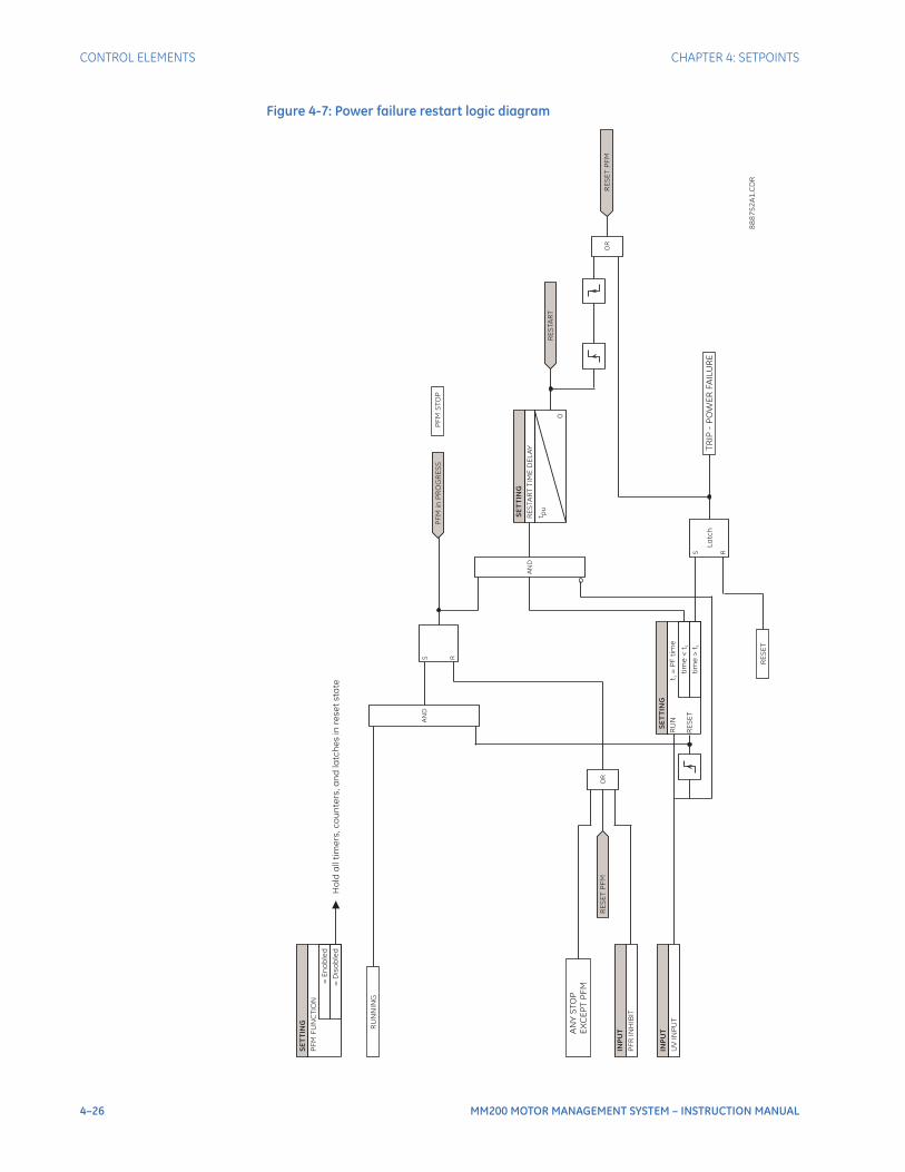
4–26 MM200 MOTOR MANAGEMENT SYSTEM – INSTRUCTION MANUAL
CONTROL ELEMENTS CHAPTER 4: SETPOINTS
Figure 4-7: Power failure restart logic diagram
SE
TT
ING
=E
na
ble
d
=D
isa
ble
d
PF
MF
UN
CT
ION
INP
UT
PF
RIN
HIB
IT
INP
UT
UV
INP
UT
RE
SE
TP
FM
OR
AN
DS R
SE
TT
I NG
tim
e<
t1
t=
PF
tim
e1
La
tc
h
S R
AN
D
SE
TT
I NG
RE
STA
RT
TIM
ED
EL
AY
tp
u
0
OR
TR
IP-
PO
WE
RFA
ILU
RE
AN
YS
TO
P
EX
CE
PT
PF
M
PF
Min
PR
OG
RE
SS
PF
MS
TO
P
RU
N
RE
SE
Ttim
e>
t1
RE
SE
T
RE
STA
RT
RE
SE
TP
FM
RU
NN
ING
Ho
lda
lltim
ers,c
ou
nte
rs,a
nd
latc
he
sin
re
se
tsta
te
88
87
52
A1
. CD
R

CHAPTER 4: SETPOINTS CONTROL ELEMENTS
MM200 MOTOR MANAGEMENT SYSTEM – INSTRUCTION MANUAL 4–27
Figure 4-8: Undervoltage restart control logic diagram
PFM IN PROGRESS
AND
OR
S
R
AND
AND
AND
AND
AND
AND
AND
RESTART
CONTACTOR A STATUS
CONTACTOR A STATUS
S
R
PFR A
PFR STOP
PFR PENDING
PFR B
888753A1.CDR

4–28 MM200 MOTOR MANAGEMENT SYSTEM – INSTRUCTION MANUAL
CONTROL ELEMENTS CHAPTER 4: SETPOINTS

MM200 MOTOR MANAGEMENT SYSTEM – INSTRUCTION MANUAL 5–1
MM200 Motor Management System
Chapter 5: Diagnostics
GEGrid Solutions
Diagnostics
The diagnostics pages display typical diagnostic information, including learned data, phasors, system counters, and system information. In the event of a trip or alarm, the diagnostic pages are often very helpful in diagnosing the cause of the condition.
Digital counters
Trip counters are typically used for scheduling inspections on equipment, for performing qualitative analysis of system problems, and for spotting trends. Several general counters are also available.
NOTE
NOTE: When the relay is powered off, the counter values are stored in non-volatile memory.
Total Number of Trips, Incomplete Sequence Trips, Overload Trips, Mechanical Jam Trips, Undercurrent Trips, Current Unbalance Trips, Ground Fault Trips, Motor Acceleration Trips.
Range: 0 to 65535 trips in steps of 1
These values display a breakdown of number of trips by type. When the total number of trips for any counter exceeds 65535, that counter is reset to 0.
Number of Motor StartsRange: 0 to 65535 starts in steps of 1
This value displays the number of accumulated motor starts or start attempts. This value may be useful information when troubleshooting a motor failure. When this counter exceeds 65535 starts, it will reset to 0.
Motor Running HoursRange: 0 to 100000 hours in steps of 1
The motor running hours timer accumulates the total running time for the motor. This value may be useful for scheduling routine maintenance. Counter will roll over to zero after range is exceeded.
Motor Stopped HoursRange: 0 to 100000 hours in steps of 1
The motor stopped hours timer accumulates the total stopped time for the motor. This value may be useful for scheduling routine maintenance.

5–2 MM200 MOTOR MANAGEMENT SYSTEM – INSTRUCTION MANUAL
LEARNED DATA CHAPTER 5: DIAGNOSTICS
Learned data
The MM200 learns the acceleration time, the starting current, the starting capacity, and the average motor load during motor starts. This data is accumulated based on the last five successful starts.
Learned Acceleration TimeRange: 0.0 to 200.0 ms in steps of 0.1 s
If motor load during starting is relatively consistent, the learned acceleration time may be used to fine tune the acceleration protection. Learned acceleration time will be the greatest time of the last five successful starts. The time is measured from the transition of motor current from zero to greater than overload pickup, until line current falls below the overload pickup level.
Learned Starting CurrentRange: 0.0 to 10000.0 A in steps of 0.1 A
The learned starting current is measured 200 ms after the transition of motor current from zero to greater than overload pickup. This should ensure that the measured current is symmetrical. The value displayed is the average of the last five successful starts. If there are less than five starts, a value of 0 seconds will be averaged in for the full five starts.
Learned Starting CapacityRange: 0 to 100% in steps of 1
The learned starting capacity is used to determine if there is enough thermal capacity to permit a start. If there is not enough thermal capacity available for a start, a start inhibit will be issued. Starting will be blocked until there is sufficient thermal capacity available.
Commands
Select the Home > Diag > Commands page to access diagnostics commands.
Figure 5-1: Diagnostics Commands
Reset
Issues a “Non-Lockout Reset” command.
Lockout Reset
Issues a “Lockout Reset” command.
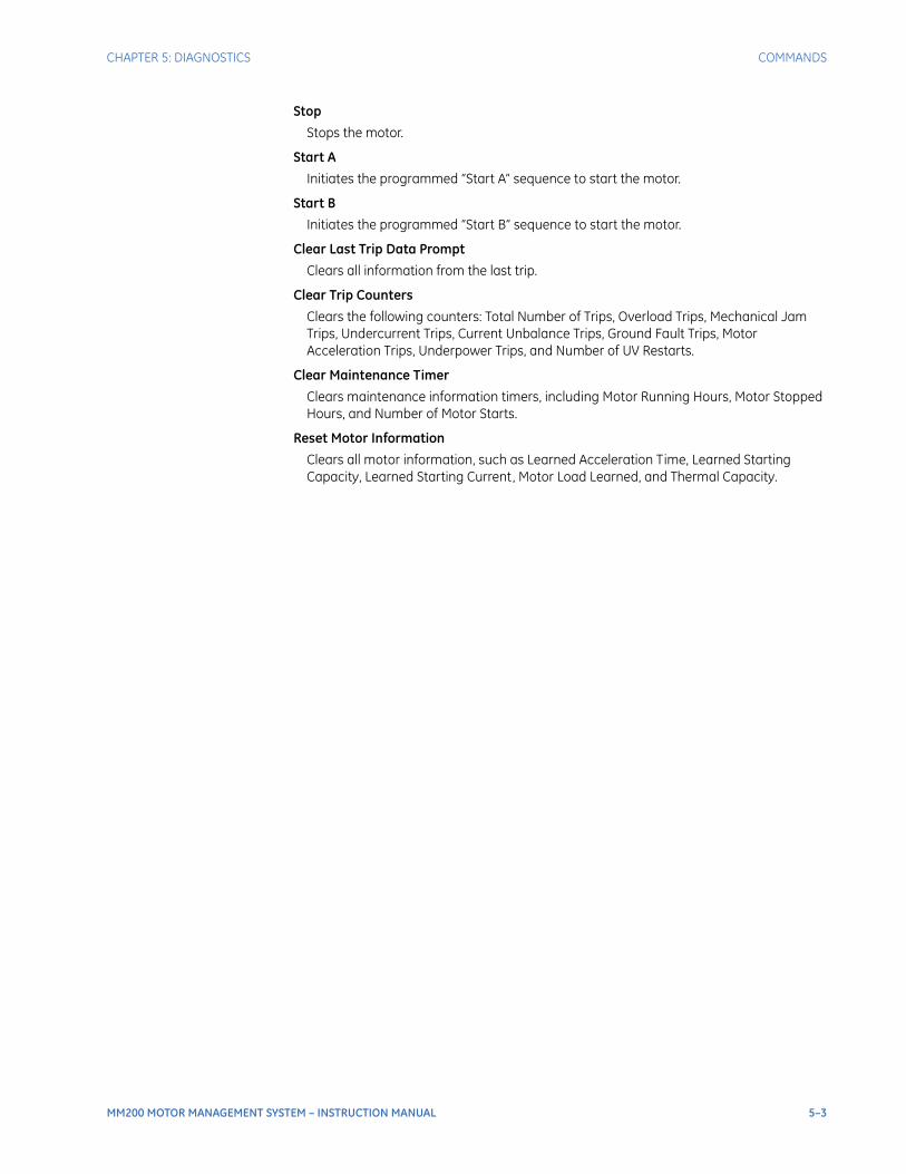
CHAPTER 5: DIAGNOSTICS COMMANDS
MM200 MOTOR MANAGEMENT SYSTEM – INSTRUCTION MANUAL 5–3
Stop
Stops the motor.
Start A
Initiates the programmed “Start A” sequence to start the motor.
Start B
Initiates the programmed “Start B” sequence to start the motor.
Clear Last Trip Data Prompt
Clears all information from the last trip.
Clear Trip Counters
Clears the following counters: Total Number of Trips, Overload Trips, Mechanical Jam Trips, Undercurrent Trips, Current Unbalance Trips, Ground Fault Trips, Motor Acceleration Trips, Underpower Trips, and Number of UV Restarts.
Clear Maintenance Timer
Clears maintenance information timers, including Motor Running Hours, Motor Stopped Hours, and Number of Motor Starts.
Reset Motor Information
Clears all motor information, such as Learned Acceleration Time, Learned Starting Capacity, Learned Starting Current, Motor Load Learned, and Thermal Capacity.

5–4 MM200 MOTOR MANAGEMENT SYSTEM – INSTRUCTION MANUAL
COMMANDS CHAPTER 5: DIAGNOSTICS

MM200 MOTOR MANAGEMENT SYSTEM – INSTRUCTION MANUAL 6–1
MM200 Motor Management System
Chapter 6: Communications
GEGrid Solutions
Communications
Communications interfaces
The MM200 has two communications interfaces:
• RS485
• Fieldbus
NOTE
NOTE: Setpoint changes related to RS485, DeviceNet, and Profibus, require a power cycle to be activated.
NOTE
NOTE: External power must be present on the Fieldbus port at power-up, in order to correctly initialize.
NOTE
NOTE: For full details, please refer to the MM200 Communications Guide, to be found on the GE Multilin web site.

6–2 MM200 MOTOR MANAGEMENT SYSTEM – INSTRUCTION MANUAL
COMMUNICATIONS INTERFACES CHAPTER 6: COMMUNICATIONS

MM200 MOTOR MANAGEMENT SYSTEM – INSTRUCTION MANUAL A–1
MM200 Motor Management System
Appendix A
GEGrid Solutions
Appendix A
Change notes
Revision history
Table A–1: Revision History
MANUAL P/N RELEASE DATE
1601-9034-A1 21 December 2007
1601-9034-A2 05 February 2008
1601-9034-A3 27 July 2008
1601-9034-A5 31 August 2009
1601-9034-A6 23 July 2010
1601-9034-A7 18 December 2015
Table A–2: Major Updates for MM200-A7
Section/Page Number CHANGES
Cover and front matter
Manual revision number from A5 to A6Added EAC logoChanged branding to GE Grid SolutionsAdded Storage and Recycling information
Ch1 Introduction, Overview section
Updated Cautions and WarningAdded For Further Assistance
Ch1 Introduction, Specifications section
Added EAC to Testing and certificationAdded Noise to Environmental specifications
Ch2 Installation Added Maintenance section
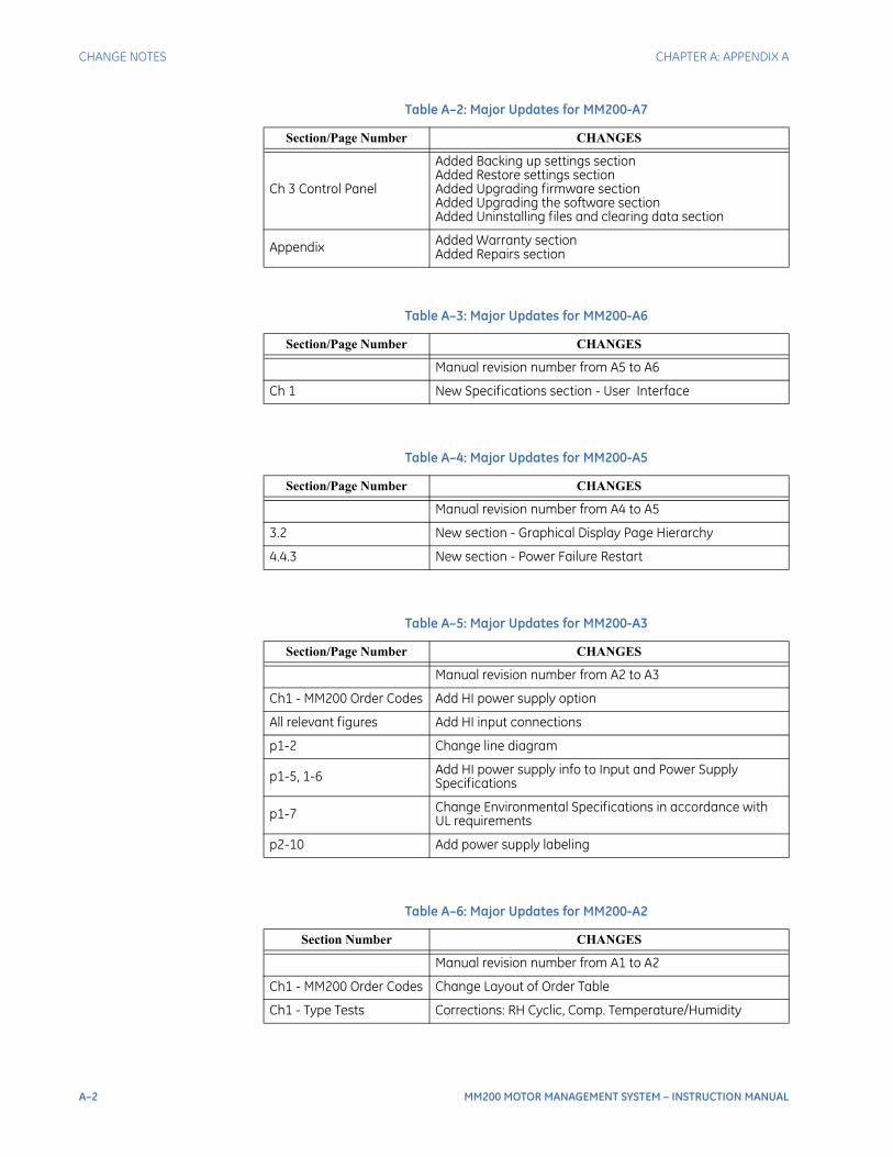
A–2 MM200 MOTOR MANAGEMENT SYSTEM – INSTRUCTION MANUAL
CHANGE NOTES CHAPTER A: APPENDIX A
Ch 3 Control Panel
Added Backing up settings sectionAdded Restore settings sectionAdded Upgrading firmware sectionAdded Upgrading the software sectionAdded Uninstalling files and clearing data section
Appendix Added Warranty sectionAdded Repairs section
Table A–3: Major Updates for MM200-A6
Section/Page Number CHANGES
Manual revision number from A5 to A6
Ch 1 New Specifications section - User Interface
Table A–4: Major Updates for MM200-A5
Section/Page Number CHANGES
Manual revision number from A4 to A5
3.2 New section - Graphical Display Page Hierarchy
4.4.3 New section - Power Failure Restart
Table A–5: Major Updates for MM200-A3
Section/Page Number CHANGES
Manual revision number from A2 to A3
Ch1 - MM200 Order Codes Add HI power supply option
All relevant figures Add HI input connections
p1-2 Change line diagram
p1-5, 1-6 Add HI power supply info to Input and Power Supply Specifications
p1-7 Change Environmental Specifications in accordance with UL requirements
p2-10 Add power supply labeling
Table A–6: Major Updates for MM200-A2
Section Number CHANGES
Manual revision number from A1 to A2
Ch1 - MM200 Order Codes Change Layout of Order Table
Ch1 - Type Tests Corrections: RH Cyclic, Comp. Temperature/Humidity
Table A–2: Major Updates for MM200-A7
Section/Page Number CHANGES

CHAPTER A: APPENDIX A WARRANTY
MM200 MOTOR MANAGEMENT SYSTEM – INSTRUCTION MANUAL A–3
Warranty
For products shipped as of 1 October 2013, GE warrants most of its GE manufactured products for 10 years. For warranty details including any limitations and disclaimers, see our Terms and Conditions at https://www.gegridsolutions.com/multilin/warranty.htm
For products shipped before 1 October 2013, the standard 24-month warranty applies.
Repairs
The firmware and software can be upgraded without return of the device to the factory.
For issues not solved by troubleshooting, the process to return the device to the factory for repair is as follows:
• Contact a GE Grid Solutions Technical Support Center. Contact information is found in the first chapter.
• Obtain a Return Materials Authorization (RMA) number from the Technical Support Center.
• Verify that the RMA and Commercial Invoice received have the correct information.
• Tightly pack the unit in a box with bubble wrap, foam material, or styrofoam inserts or packaging peanuts to cushion the item(s). You may also use double boxing whereby you place the box in a larger box that contains at least 5 cm of cushioning material.
• Ship the unit by courier or freight forwarder, along with the Commercial Invoice and RMA, to the factory.
Customers are responsible for shipping costs to the factory, regardless of whether the unit is under warranty.
• Fax a copy of the shipping information to the GE Grid Solutions service department.
Use the detailed return procedure outlined at
https://www.gegridsolutions.com/multilin/support/ret_proc.htm
The current warranty and return information are outlined at
https://www.gegridsolutions.com/multilin/warranty.htm

A–4 MM200 MOTOR MANAGEMENT SYSTEM – INSTRUCTION MANUAL
REPAIRS CHAPTER A: APPENDIX A