Embed Size (px)
Citation preview
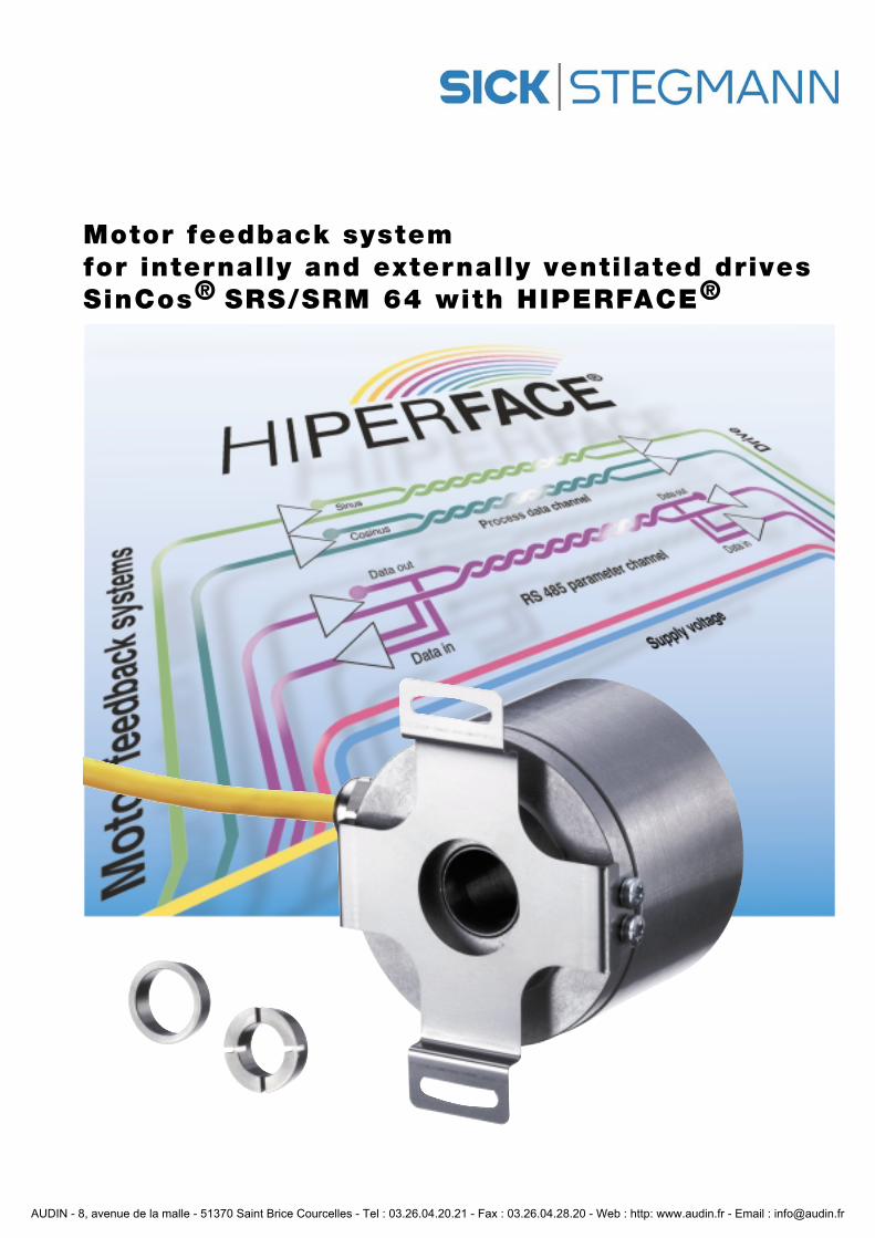
Motor feedback systemfor internally and externally ventilated drivesSinCos® SRS/SRM 64 with HIPERFACE®
AUDIN - 8, avenue de la malle - 51370 Saint Brice Courcelles - Tel : 03.26.04.20.21 - Fax : 03.26.04.28.20 - Web : http: www.audin.fr - Email : [email protected]
Inhaltsverzeichnis
Section Title Page
1 HIPERFACE® * 3
2 Recommended installation 4
3 Technical data and characteristics 5
4 HIPERFACE® type-specific 6-7
5 Signal specification 8
6 Restart 9
7 Dimensional drawing and recommended installation 10
8 Pin allocation 11
9 Accessories 11
* HIPERFACE®: For detailed information see Product information 910 980 003 391
2
Highlights
• 1024 sine/cosine cycles per revolution• Absolute with 15 bits per revolution over 12 bits (4096) revolutions• Electronic type label
• Particularly suitable for fitting to internally and externally ventilated motors• Very small rotation angle error arising from mechanical fitting, because of
double taper shaft coupling
AUDIN - 8, avenue de la malle - 51370 Saint Brice Courcelles - Tel : 03.26.04.20.21 - Fax : 03.26.04.28.20 - Web : http: www.audin.fr - Email : [email protected]
1.HIPERFACE®
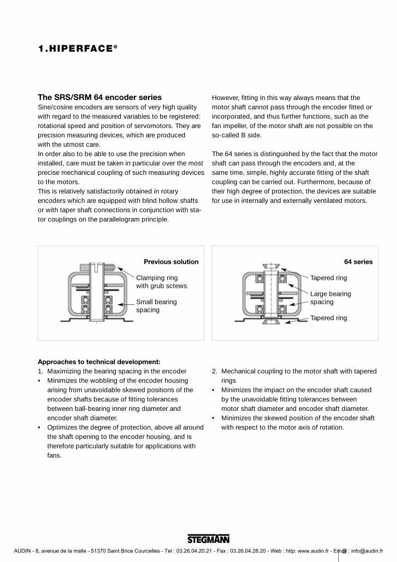
The SRS/SRM 64 encoder seriesSine/cosine encoders are sensors of very high qualitywith regard to the measured variables to be registered: rotational speed and position of servomotors. They areprecision measuring devices, which are produced with the utmost care. In order also to be able to use the precision wheninstalled, care must be taken in particular over the most precise mechanical coupling of such measuring devicesto the motors.This is relatively satisfactorily obtained in rotaryencoders which are equipped with blind hollow shaftsor with taper shaft connections in conjunction with sta-tor couplings on the parallelogram principle.
However, fitting in this way always means that themotor shaft cannot pass through the encoder fitted or incorporated, and thus further functions, such as thefan impeller, of the motor shaft are not possible on the so-called B side.
The 64 series is distinguished by the fact that the motorshaft can pass through the encoders and, at the same time, simple, highly accurate fitting of the shaftcoupling can be carried out. Furthermore, because of their high degree of protection, the devices are suitablefor use in internally and externally ventilated motors.
3
Approaches to technical development:1. Maximizing the bearing spacing in the encoder • Minimizes the wobbling of the encoder housing
arising from unavoidable skewed positions of the encoder shafts because of fitting tolerances between ball-bearing inner ring diameter and encoder shaft diameter.
• Optimizes the degree of protection, above all aroundthe shaft opening to the encoder housing, and is therefore particularly suitable for applications with fans.
2. Mechanical coupling to the motor shaft with taperedrings
• Minimizes the impact on the encoder shaft caused by the unavoidable fitting tolerances between motor shaft diameter and encoder shaft diameter.
• Minimizes the skewed position of the encoder shaft with respect to the motor axis of rotation.
Previous solution
Clamping ringwith grub sctews
Small bearingspacing
64 series
Tapered ring
Large bearing spacing
Tapered ring
AUDIN - 8, avenue de la malle - 51370 Saint Brice Courcelles - Tel : 03.26.04.20.21 - Fax : 03.26.04.28.20 - Web : http: www.audin.fr - Email : [email protected]
2. Recommended installation
4
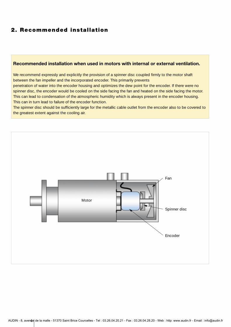
Recommended installation when used in motors with internal or external ventilation.
We recommend expressly and explicitly the provision of a spinner disc coupled firmly to the motor shaftbetween the fan impeller and the incorporated encoder. This primarily prevents penetration of water into the encoder housing and optimizes the dew point for the encoder. If there were nospinner disc, the encoder would be cooled on the side facing the fan and heated on the side facing the motor.This can lead to condensation of the atmospheric humidity which is always present in the encoder housing.This can in turn lead to failure of the encoder function.The spinner disc should be sufficiently large for the metallic cable outlet from the encoder also to be covered tothe greatest extent against the cooling air.
Motor
Fan
Spinner disc
Encoder
AUDIN - 8, avenue de la malle - 51370 Saint Brice Courcelles - Tel : 03.26.04.20.21 - Fax : 03.26.04.28.20 - Web : http: www.audin.fr - Email : [email protected]
5
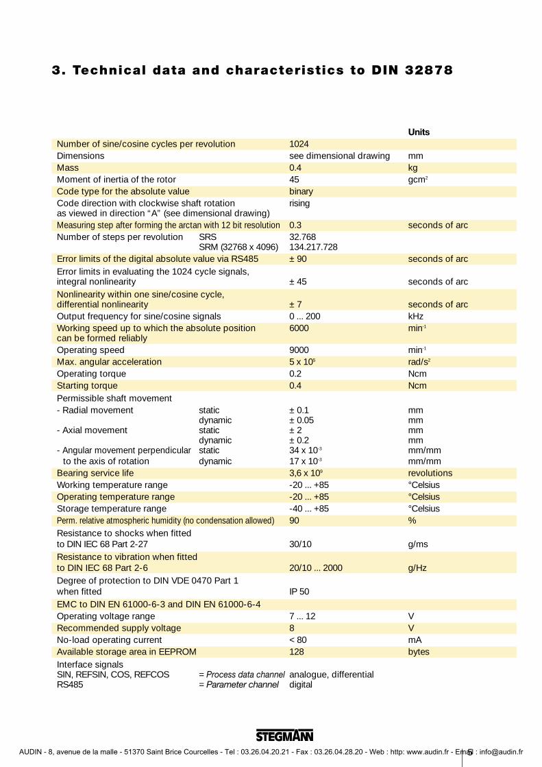
3. Technical data and characteristics to DIN 32878
UnitsNumber of sine/cosine cycles per revolution 1024Dimensions see dimensional drawing mmMass 0.4 kgMoment of inertia of the rotor 45 gcm2
Code type for the absolute value binaryCode direction with clockwise shaft rotation risingas viewed in direction “A” (see dimensional drawing)Measuring step after forming the arctan with 12 bit resolution 0.3 seconds of arcNumber of steps per revolution SRS 32.768
SRM (32768 x 4096) 134.217.728Error limits of the digital absolute value via RS485 ± 90 seconds of arcError limits in evaluating the 1024 cycle signals,integral nonlinearity ± 45 seconds of arcNonlinearity within one sine/cosine cycle,differential nonlinearity ± 7 seconds of arcOutput frequency for sine/cosine signals 0 ... 200 kHzWorking speed up to which the absolute position 6000 min-1
can be formed reliablyOperating speed 9000 min-1
Max. angular acceleration 5 x 10⁵ rad/s2
Operating torque 0.2 NcmStarting torque 0.4 NcmPermissible shaft movement- Radial movement static ± 0.1 mm
dynamic ± 0.05 mm- Axial movement static ± 2 mm
dynamic ± 0.2 mm- Angular movement perpendicular static 34 x 10-3 mm/mm
to the axis of rotation dynamic 17 x 10-3 mm/mmBearing service life 3,6 x 10⁹ revolutionsWorking temperature range -20 ... +85 °CelsiusOperating temperature range -20 ... +85 °CelsiusStorage temperature range -40 ... +85 °CelsiusPerm. relative atmospheric humidity (no condensation allowed) 90 %Resistance to shocks when fittedto DIN IEC 68 Part 2-27 30/10 g/msResistance to vibration when fittedto DIN IEC 68 Part 2-6 20/10 ... 2000 g/HzDegree of protection to DIN VDE 0470 Part 1when fitted IP 50EMC to DIN EN 61000-6-3 and DIN EN 61000-6-4Operating voltage range 7 ... 12 VRecommended supply voltage 8 VNo-load operating current < 80 mAAvailable storage area in EEPROM 128 bytesInterface signalsSIN, REFSIN, COS, REFCOS = Process data channel analogue, differentialRS485 = Parameter channel digital
AUDIN - 8, avenue de la malle - 51370 Saint Brice Courcelles - Tel : 03.26.04.20.21 - Fax : 03.26.04.28.20 - Web : http: www.audin.fr - Email : [email protected]
6
HIPERFACE® defines the physical interface of the motor feedback systems and also the transmission protocol of the parameter channel and the structure of commands, messages and functions (see HIPERFACE®
parameter channel datasheet)
The functional scope can vary from type to type.
The HIPERFACE® functions of the SRS/SRM 64 are described below.
4.HIPERFACE® Type specific
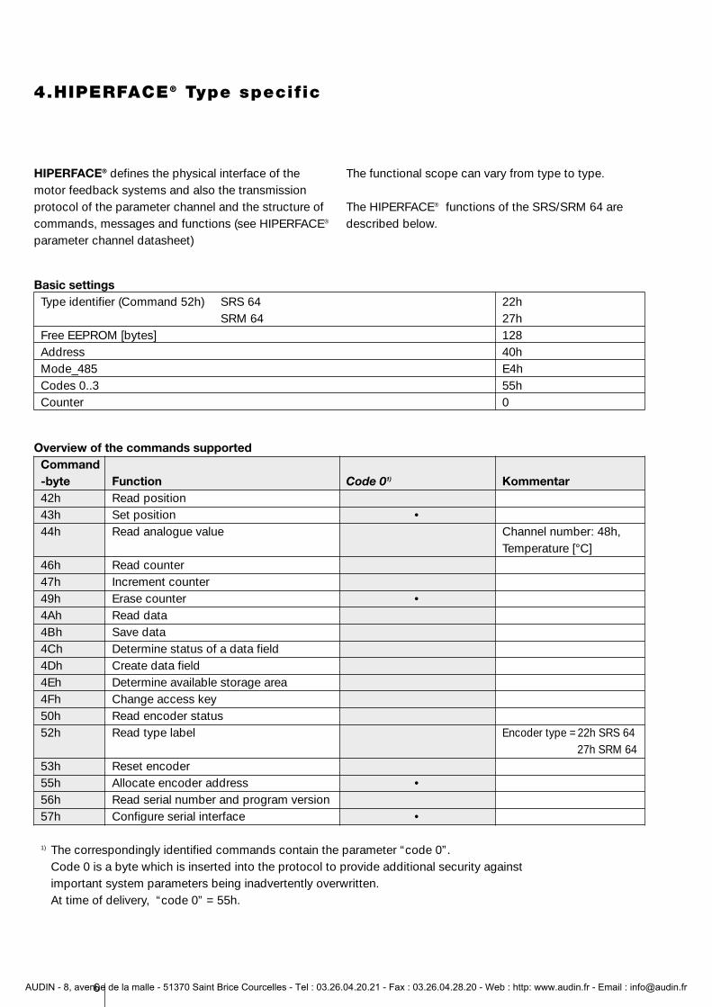
Basic settingsType identifier (Command 52h) SRS 64 22h
SRM 64 27hFree EEPROM [bytes] 128Address 40hMode_485 E4hCodes 0..3 55hCounter 0
Overview of the commands supportedCommand-byte Function Code 01) Kommentar42h Read position43h Set position •44h Read analogue value Channel number: 48h,
Temperature [°C]46h Read counter47h Increment counter49h Erase counter •4Ah Read data4Bh Save data4Ch Determine status of a data field4Dh Create data field4Eh Determine available storage area4Fh Change access key50h Read encoder status52h Read type label Encoder type = 22h SRS 64
27h SRM 6453h Reset encoder55h Allocate encoder address •56h Read serial number and program version57h Configure serial interface •
1) The correspondingly identified commands contain the parameter “code 0”. Code 0 is a byte which is inserted into the protocol to provide additional security against important system parameters being inadvertently overwritten.At time of delivery, “code 0” = 55h.
AUDIN - 8, avenue de la malle - 51370 Saint Brice Courcelles - Tel : 03.26.04.20.21 - Fax : 03.26.04.28.20 - Web : http: www.audin.fr - Email : [email protected]
7
4.HIPERFACE® Type specific
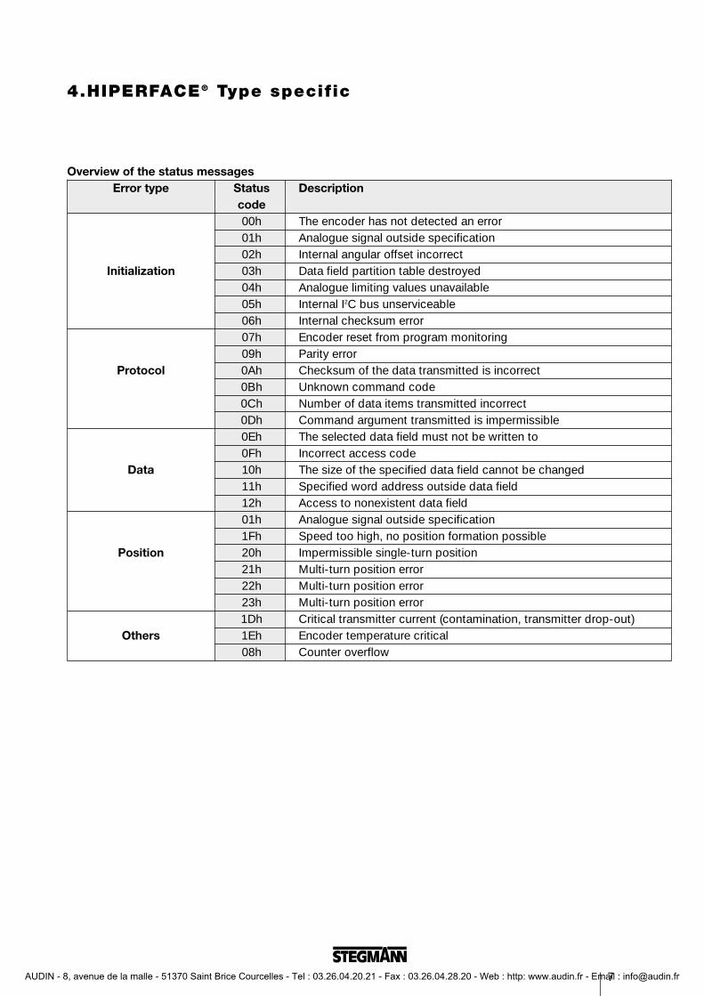
Overview of the status messagesError type Status Description
code00h The encoder has not detected an error01h Analogue signal outside specification02h Internal angular offset incorrect
Initialization 03h Data field partition table destroyed04h Analogue limiting values unavailable05h Internal I2C bus unserviceable06h Internal checksum error07h Encoder reset from program monitoring09h Parity error
Protocol 0Ah Checksum of the data transmitted is incorrect0Bh Unknown command code0Ch Number of data items transmitted incorrect0Dh Command argument transmitted is impermissible0Eh The selected data field must not be written to0Fh Incorrect access code
Data 10h The size of the specified data field cannot be changed11h Specified word address outside data field12h Access to nonexistent data field01h Analogue signal outside specification1Fh Speed too high, no position formation possible
Position 20h Impermissible single-turn position21h Multi-turn position error22h Multi-turn position error23h Multi-turn position error1Dh Critical transmitter current (contamination, transmitter drop-out)
Others 1Eh Encoder temperature critical08h Counter overflow
AUDIN - 8, avenue de la malle - 51370 Saint Brice Courcelles - Tel : 03.26.04.20.21 - Fax : 03.26.04.28.20 - Web : http: www.audin.fr - Email : [email protected]
8
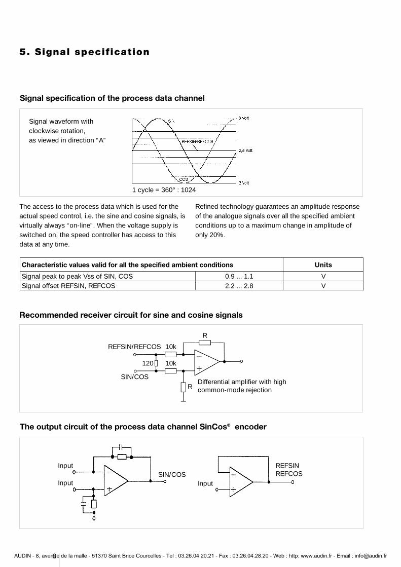
5. Signal specification
Signal specification of the process data channel
The access to the process data which is used for theactual speed control, i.e. the sine and cosine signals, isvirtually always “on-line”. When the voltage supply isswitched on, the speed controller has access to thisdata at any time.
Refined technology guarantees an amplitude responseof the analogue signals over all the specified ambientconditions up to a maximum change in amplitude ofonly 20%.
Characteristic values valid for all the specified ambient conditions
Signal peak to peak Vss of SIN, COSSignal offset REFSIN, REFCOS
0.9 ... 1.12.2 ... 2.8
VV
Units
Recommended receiver circuit for sine and cosine signals
The output circuit of the process data channel SinCos® encoder
Signal waveform withclockwise rotation,as viewed in direction “A”
Input
Input InputSIN/COS
REFSINREFCOS
1 cycle = 360° : 1024
Differential amplifier with highcommon-mode rejection
REFSIN/REFCOS
SIN/COS
120
10k
10k
R
R
AUDIN - 8, avenue de la malle - 51370 Saint Brice Courcelles - Tel : 03.26.04.20.21 - Fax : 03.26.04.28.20 - Web : http: www.audin.fr - Email : [email protected]
9
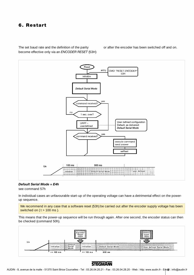
Default Serial Mode = E4hsee command 57h
In individual cases an unfavourable start-up of the operating voltage can have a detrimental effect on the power-up sequence.
This means that the power-up sequence will be run through again. After one second, the encoder status can thenbe checked (command 50h).
6. Restart
We recommend in any case that a software reset (53h) be carried out after the encoder supply voltage has beenswitched on ( t > 100 ms ).
The set baud rate and the definition of the paritybecome effective only via an ENCODER RESET (53H)
or after the encoder has been switched off and on.
AUDIN - 8, avenue de la malle - 51370 Saint Brice Courcelles - Tel : 03.26.04.20.21 - Fax : 03.26.04.28.20 - Web : http: www.audin.fr - Email : [email protected]
10
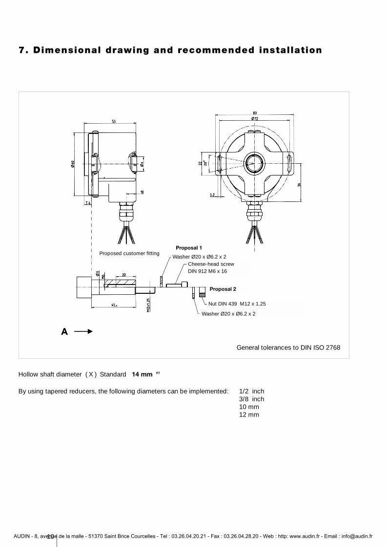
7. Dimensional drawing and recommended installation
General tolerances to DIN ISO 2768
Hollow shaft diameter ( X ) Standard 14 mm F7
By using tapered reducers, the following diameters can be implemented: 1/2 inch3/8 inch10 mm12 mm
Proposed customer fittingProposal 1
Washer Ø20 x Ø6.2 x 2Cheese-head screwDIN 912 M6 x 16
Proposal 2
Nut DIN 439 M12 x 1.25
Washer Ø20 x Ø6.2 x 2
AUDIN - 8, avenue de la malle - 51370 Saint Brice Courcelles - Tel : 03.26.04.20.21 - Fax : 03.26.04.28.20 - Web : http: www.audin.fr - Email : [email protected]
11
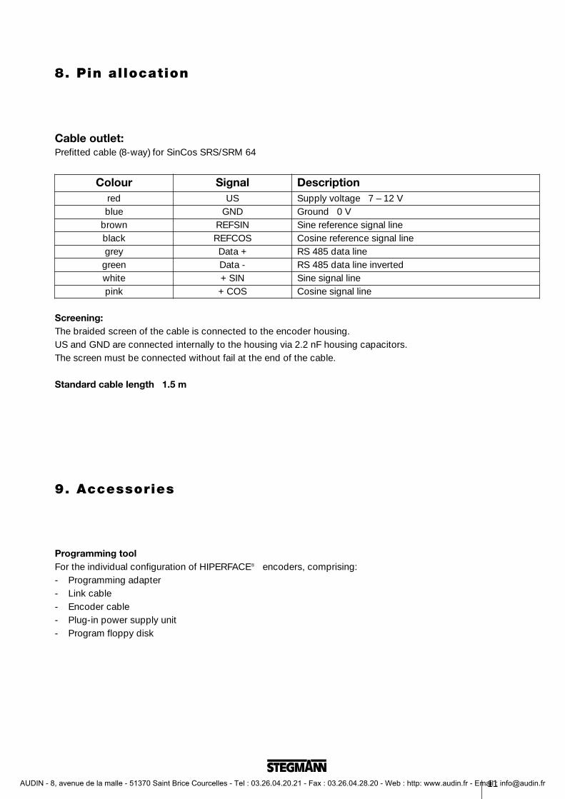
8. Pin allocation
Colour Signal Descriptionred US Supply voltage 7 – 12 Vblue GND Ground 0 V
brown REFSIN Sine reference signal lineblack REFCOS Cosine reference signal linegrey Data + RS 485 data line
green Data - RS 485 data line invertedwhite + SIN Sine signal linepink + COS Cosine signal line
Screening:The braided screen of the cable is connected to the encoder housing.US and GND are connected internally to the housing via 2.2 nF housing capacitors.The screen must be connected without fail at the end of the cable.
Standard cable length 1.5 m
Cable outlet: Prefitted cable (8-way) for SinCos SRS/SRM 64
9. Accessories
Programming toolFor the individual configuration of HIPERFACE® encoders, comprising:- Programming adapter- Link cable- Encoder cable- Plug-in power supply unit- Program floppy disk
AUDIN - 8, avenue de la malle - 51370 Saint Brice Courcelles - Tel : 03.26.04.20.21 - Fax : 03.26.04.28.20 - Web : http: www.audin.fr - Email : [email protected]
Stegmann GmbH & Co. KG Postbox 15 60D - 78156 DonaueschingenDürrheimer Straße 36D - 78166 DonaueschingenTelephone ( 07 71 ) 8 07 - 0Telefax ( 07 71 ) 80 71 00www. stegmann.dee-mail: info@ stegmann.de
Precisionin motion
Incremental andabsolute measuring systems.Feedback systemsfor servomotors.
Synchronous motorsStepping motorsControl units for motorsGears · Actuating drivesPositioning drives
© S
tegm
ann
Gm
bH &
Co.
KG
200
3. P
rinte
d in
Ger
man
y. A
ll rig
hts
rese
rved
.P
rodu
ct In
form
atio
n 91
003
010
461
3, I
ssue
05/
0305
03/1
/3/0
503
ISO 9001EN 29001
AUDIN - 8, avenue de la malle - 51370 Saint Brice Courcelles - Tel : 03.26.04.20.21 - Fax : 03.26.04.28.20 - Web : http: www.audin.fr - Email : [email protected]