Embed Size (px)
Citation preview

Motor Development for Electrical Drive
Systems
(1) (2) (3)
Sources: (1) Voith, Heidenheim, Germany; (2) ELIN EBG Motoren GmbH, Weiz, Austria;
(3) Siemens AG, Germany
Issue SS 2017 Prof. Dr.-Ing. habil. Dr. h.c. Andreas Binder
Institut für Elektrische
Energiewandlung

MMoottoorr DDeevveellooppmmeenntt ffoorr EElleeccttrriicc DDrriivvee SSyysstteemmss PPrreeppaarraattiioonn ffoorr eexxaammiinnaattiioonn
Darmstadt University of Technology Department of Electrical Energy Conversion
Prof. Dr.-Ing. habil. Dr. h.c. A. Binder
OOral examination to lecture
„MMoottoorr DDeevveellooppmmeenntt ffoorr EElleeccttrriicc DDrriivvee SSyysstteemmss“
Examination questions (10 min. per each question):
Rotating permanent magnet drives - synchronous servo-drives:
1) How is the magnetic operating point of the motor determined at no-load operation? How will this
operating point be shifted at load and by temperature change?
2) Draw some typical B(H)-characteristics of permanent magnets and explain them.
3) Sketch and describe the operating characteristics of the PM synchronous motor with rotor
position control.
4) How can field weakening be realized for PM machines?
5) Explain the operating mode of block-current commutated PM synchronous machines! Why is this
motor type called “brushless DC”-drive?
6) Explain the sinus-commutated operating mode of PM synchronous machines! Name the
differences to block-commutation and indicate some advantages and disadvantages!
7) Explain the structure of rotors with surface mounted and buried magnets! What does flux
concentration mean? How is it realized?
8) Describe the structure of a position-controlled PM servo drive. Name some application domains.
9) What does “q-current operation” mean? Explain it with help of the phasor diagram. How does the
torque generation at this operation mode look like (Explain it with the air gap field)?
10) Describe the danger of demagnetization of permanent magnets through the stator field at load /
overload!
11) Which electromagnetic and mechanic parameters are essential for design of high-speed drives
with high utilization of active mass?
PM-linear drives:
1) How are PM linear drives built? Give an overview of the variety of different configurations.
2) Discuss the tangential and normal force density of PM linear motors and give some typical
numerical values, depending on type of motor cooling!
3) Name typical values for the acceleration, the speed, the movement distances of PM linear
machines! Why is the efficiency of linear machines lower than the efficiency of rotating
machines?
4) Name the basic components of a typical PM linear drive. Sketch the structure of the complete
drive system!
PM high-torque drives:
1) What characteristics do synchronous machines with high pole count have and when are they
used?
2) Why is the active mass of PM synchronous machines with high pole count relatively smaller for a
given torque, compared with machines with low pole count (e.g. 2 pole machine) ?
3) Describe the basic ideas of modular synchronous machines. What is a tooth wound armature
winding?
4) Which are the advantages and disadvantages of modular synchronous machines? Where are they
used?
5) How does the transversal flux machine operate in principle? For which application domains is it
well suitable?
6) Describe the basic characteristics of the transversal flux machine. Which loss components are
most dominant?
7) Sketch different structures of transversal flux machines and name the advantages and
disadvantages of them!
MMoottoorr DDeevveellooppmmeenntt ffoorr EElleeccttrriicc DDrriivvee SSyysstteemmss PPrreeppaarraattiioonn ffoorr eexxaammiinnaattiioonn
Darmstadt University of Technology Department of Electrical Energy Conversion
Prof. Dr.-Ing. habil. Dr. h.c. A. Binder
Switched reluctance drives:
1) Describe the motor and inverter design, and the operation modes of switched reluctance drives!
2) What are the advantages and disadvantages of the switched reluctance drive, compared to
traditional rotating field machines?
3) Explain the torque generation of the switched reluctance machine on the basis of the variation of
phase inductance at rotor rotation!
4) Sketch the “maximum torque vs. speed”-curve of the switched reluctance drive and explain the
particular speed sections!
5) Why is for switched reluctance machines a high saturation aimed to get high machine utilization ?
Explain the principle by means of the “flux linkage –current”-characteristic for different rotor
positions!
6) Explain the causes of torque ripple generated by switched reluctance machines!
7) Why do switched reluctance machines tend to generate electromagnetically excited acoustic
noise? Describe the mechanism of this effect! With which dominant frequency does this noise
generation occur?
8) Name typical application domains for switched reluctance drives, and the reasons why they are
used.
Synchronous reluctance motors:
1) Describe the stator and rotor design and the operation modes of synchronous reluctance motors!
Which parameters are significant for torque generation?
2) Draw the phasor diagram of the synchronous reluctance machine in motor operation ! Explain the
main parameter load angle, phase angle, voltage and current !
3) The synchronous reluctance machine is supplied by fixed stator voltage and frequency: Sketch
the torque’s dependency on load angle at neglected stator resistance and give the formula.
How does the stator resistance change the torque curve?
4) Sketch rotor structures of the synchronous reluctance motor for increased ratio Xd/Xq !
5) Name typical application domains for synchronous reluctance motors, and the reasons why they
are used. Why are synchronous reluctance motors built and used only in lower power range ?
PM synchronous machines with rotor cage:
1) Describe the stator and rotor design of a PM synchronous machine with rotor cage. Give
applications, where these motors are used!
2) Explain the flux concentration effect and sketch possible rotor configurations! What is the
concentration factor?
3) Give the characteristic “torque vs. load angle” for a grid-operated PM synchronous machine with
buried rotor magnets! What condition is necessary for minimum magnet strength?
4) Discuss the peculiarities of the starting characteristic “torque vs. speed” of grid-operated PM
synchronous machines with rotor cage!
5) Describe the synchronization process of the line-started PM synchronous machine with rotor cage!
What is the critical slip?
Grid-operated asynchronous machines with squirrel-cage rotor – standard motors:
1) Explain the dependence of motor efficiency and the efficiency maximum at variable load!
2) Name the basic components of standard asynchronous motors! What is “standardized” at these
motors and up to which shaft height?
3) Sketch the speed-torque characteristic of squirrel-cage asynchronous motors by mains supply
with fixed voltage and frequency! What are “torque classifications”?
4) What are the main loss groups in line-operated squirrel-cage asynchronous machines? How do
they influence the operational behaviour?
MMoottoorr DDeevveellooppmmeenntt ffoorr EElleeccttrriicc DDrriivvee SSyysstteemmss PPrreeppaarraattiioonn ffoorr eexxaammiinnaattiioonn
Darmstadt University of Technology Department of Electrical Energy Conversion
Prof. Dr.-Ing. habil. Dr. h.c. A. Binder
5) Explain the physical nature of asynchronous space harmonic torque! How is this additional torque
component generated? How it is influencing motor performance?
6) What are space harmonics of air gap flux density? Give an overview on ordinal numbers
(formula) of stator and rotor field harmonics in squirrel-cage asynchronous machines!
7) Why do cage rotors of grid-operated asynchronous machines have skewed bars?
8) Explain the appearance of inter-bar currents and inter-bar current losses in cage rotors. How do
these losses depend on inter-bar resistance and slot number ratio Qs/Qr?
9) How are rotor time harmonic currents generated in line-fed asynchronous machines? How do
they contribute to so-called additional losses?
10) Why do synchronous space harmonic torque components appear? How does this additional
torque component change the speed-torque characteristic of the asynchronous machine?
11) Explain the generation of magnetic noise in asynchronous machines at line–operation! Explain
the physical background step by step from the magnetic air gap field to the sound pressure waves
in air!
12) What are “slot harmonic” flux density waves? Give an example! Why do different slot number
ratios Qs/Qr have significant influence on the stimulation of magnetic noise?
Inverter-fed standard induction machines:
1) Explain the operational behaviour (maximum torque-speed curve, voltage speed-curve, power-
speed curve) of inverter-fed standard- induction machines without and with influence of the stator
winding resistance!
2) Sketch the steady state torque-speed characteristic (thermal limit of motor winding) of the
variable-speed asynchronous drive with shaft-mounted fan cooling! Explain the particular speed
sections!
3) Discuss the operational mode (maximum torque-speed curve, voltage speed-curve, power-speed
curve) of standard induction machines with “steep” and “flat” voltage-frequency characteristic!
Explain, why the same motor with flat characteristic can deliver a higher (how many times?)
power!
4) Explain the field-weakening operation of inverter-fed asynchronous machines! How is the field-
weakening realized? Why is the field-weakening used? What natural limitations in torque-speed
range exist at field-weakening?
5) Name the loss components in inverter-fed asynchronous machine with shaft-mounted fan! How
do they change with variable stator frequency? What effect has the variable speed (variable loss)
on the steady state torque-speed characteristic concerning thermal limits?
Induction machines, designed especially for inverter operation:
1) How can field weakening range (= constant power range) be extended by serial and parallel
switching of the windings?
2) What methods of creating a wide field weakening range do you know? What typical field
weakening range (= constant power range) is possible? Give applications!
3) How is the shaft-height defined? With which methods can a significant increase of power per
shaft-height be obtained in inverter-fed special induction machines, compared to standard
induction machines?
4) Sketch maximum torque-speed curve, voltage speed-curve, power-speed curve of an inverter-fed
induction motor with external fan cooling!
5) What is the difference between “field-oriented control” and operation with “U/f- characteristic”?
6) Name some special features of induction machines, which are designed especially for inverter-
operation! In what way do they differ from the standard induction machines?

MMoottoorr DDeevveellooppmmeenntt ffoorr EElleeccttrriicc DDrriivvee SSyysstteemmss PPrreeppaarraattiioonn ffoorr eexxaammiinnaattiioonn
Darmstadt University of Technology Department of Electrical Energy Conversion
Prof. Dr.-Ing. habil. Dr. h.c. A. Binder
Effects in asynchronous machines, caused by inverter-operation:
1) Why do additional time harmonic currents occur both in stator and rotor winding in asynchronous
machines at inverter supply? Which are the dominating frequencies, if the inverter is operated
with pulse-width modulated inverter output voltage?
2) Explain the reasons for additional losses in asynchronous machines at inverter supply!
3) How is a “pulsating torque” component generated in asynchronous machines at inverter supply?
Name the dominant frequency! Why may this oscillating torque be harmful in some application
cases?
4) Why are space harmonic additional torque components (asynchronous and synchronous harmonic
torque) generally insignificant at inverter supply?
5) Why does inverter supply lead to an additional electromagnetic noise generation? Which
frequency and pulsation mode of the motor housing are dominating?
6) Why can the time harmonic content of current in asynchronous machines be obviously reduced
with fast-switching IGBT voltage DC link converter?
7) Which parasitic effects occur due to fast-switching IGBT voltage DC link converter in
asynchronous machines and in the motor cables?
8) Explain the appearance of an increased motor terminal voltage at inverter supply, caused by
voltage wave reflections!
9) Why will the “first” coil of each motor phase be the most highly charged with voltage stress at
inverter supply with fast-switching IGBTs?
Rotor balancing:
1) What is “unbalance” of a rotor defined? How is this unbalance disturbing motor operation? How
is its effect encountered by the balancing procedure in principle?
2) Define the static and dynamic unbalance by means of a simple rotor model and give the formulas
for their definition! How do both unbalance modes manifest at motor operation?
3) What is meant by “rigid body balancing”? Describe the configuration of a balancing machine and
its function!
4) Describe the difference between a rigid and an elastic rotor! Explain the natural bending
frequencies and their influence on the oscillatory behaviour of rotor and on the balancing
process?
5) How can be estimated the magnitude of unbalance by a vibration measurement of an (electrical)
machine?
6) Give a quantitative measure which describes the quality of balancing of a rotor? How is it
defined? Give examples (numerical values) for different applications!

Motor development 0/1 General
TU Darmstadt Institute for Electrical Energy Conversion
Contents Literature 0/3 List of symbols 0/4 1. Permanent magnet synchronous machines as “brushless DC drives” 1/1 1.1 Basic principles of brushless DC drives 1/1 1.1.1 Basic function of PM synchronous machine 1/2 1.1.2 Permanent magnet technology 1/5 1.1.3 Torque generation in PM machines with block and sine wave current operation 1/11 1.1.4 Induced no-load voltage (“back EMF”) in PM machines 1/14 1.1.5 Equivalent circuit of PM synchronous machines 1/20 1.1.6 Stator current generation 1/22 1.1.7 Operating limits of brushless DC drives 1/24 1.1.8 Torque ripple of brushless DC motors 1/28 1.1.9 Significance of torque ripple for motor and drive performance 1/33 1.2 Brushless DC drive systems 1/35 1.2.1 Block commutated drives 1/35 1.2.2 Sine wave commutated drives 1/36 1.3 High speed PM machines 1/38 1.3.1 How to increase power of a given machine? 1/38 1.3.2 Flux weakening with negative d-current 1/39 1.3.3 Rotor configurations for flux weakening 1/43 1.3.4 Applications: Tools machinery and electric cars 1/44 1.3.5 Additional losses at high speed 1/47 1.4 PM Linear machines 1/49 1.4.1 Application of high performance linear PM motors 1/49 1.4.2 Basic elements of linear PM motors 1/50 1.4.3 Forces and acceleration in linear PM motors 1/52 1.4.4 Features of linear PM motors 1/54 1.5 High torque machines 1/56 1.5.1 Hi-torque motors with conventional distributed winding 1/57 1.5.2 Modular synchronous machines 1/59 1.5.3 Transversal flux machines 1/64 2. Reluctance motors 2/1 2.1 Switched reluctance drives 2/1 2.1.1 Basic function 2/1 2.1.2 Flux linkage per phase 2/3 2.1.3 Voltage and torque equation 2/5 2.1.4 SR machine operation at ideal conditions 2/6 2.1.5 Calculating torque in saturated SR machine 2/8 2.1.6 SR machine operation at real conditions 2/11 2.1.7 SR Drive operation – torque-speed characteristic 2/14 2.1.8 Inverter rating 2/16 2.1.9 Motor technology and performance 2/18 2.1.10 Applications of SR drives 2/20 2.2 Synchronous reluctance machines 2/21 2.2.1 Basic function of synchronous reluctance machine 2/21 2.2.2 Voltage and torque equation of synchronous reluctance machine 2/23
Motor development 0/2 General
TU Darmstadt Institute for Electrical Energy Conversion
2.2.3 Operation of synchronous reluctance machine at constant voltage and frequency 2/26 2.2.4 Stator flux linkage, saturation of iron 2/28 2.2.5 Synchronous reluctance machine performance and application 2/32 2.2.6 Asynchronous starting 2/34 2.2.7 Special rotor designs for increased ratio Xd/Xq 2/36 3. PM synchronous machines with cage rotor 3/1 3.1 Basic motor function and rotor design 3/1 3.2 Motor performance at synchronous speed 3/4 3.3 Stress of permanent magnets at failures 3/10 3.4 Torque at asynchronous starting 3/11 4. Induction machines 4/1 4.1 Significance and features of induction machines 4/1 4.2 Fundamental wave model of line-operated induction machine 4/6 4.3 Voltage limits and premium efficiency machines 4/16 4.4 Space harmonic effects in induction machines 4/22 4.4.1 Field space harmonics and current time harmonics at sinusoidal stator voltage 4/22 4.4.2 Harmonic torques 4/32 4.4.3 Rotor skew and inter-bar currents 4/38 4.4.4 Electromagnetic acoustic noise 4/47 5. Inverter-fed induction machines 5/1 5.1 Basic performance of variable-speed induction machines 5/1 5.2 Drive characteristics of inverter-fed standard induction motors 5/6 5.3 Features of special induction motors for inverter-operation 5/9 5.4 Influence of inverter harmonics on motor performance 5/15 6. du/dt-effects in inverter-fed machines 6/1 6.1 Voltage wave reflection at motor terminals 6/1 6.2 HF voltage distribution in armature winding 6/9 6.3 Insulation stress of AC winding at inverter supply 6/12 6.4 System design of inverter drives coping with big du/dt 6/14 6.5 Combined inverter-motors 6/16 7. Mechanical motor design 7/1 7.1 Rotor balancing 7/1 7.1.1 Imbalance of rigid rotor bodies 7/2 7.1.2 Balancing equation for rigid rotor bodies 7/6 7.1.3 Balancing of rigid rotors 7/7 7.1.4 Balancing of complete motor system 7/10 7.1.5 Elastic rotor system - Vibrations of rotors 7/13 7.1.6 Balancing of elastic rotors 7/18 8. Stepper motors 8/1 8.1 Basic principle of operation of steppers 8/2 8.2 Stepper motor design 8/8 8.3 Driving circuits for stepper motors 8/12 8.4 Torque characteristics of stepper motors 8/15

Motor development 0/3 General
TU Darmstadt Institute for Electrical Energy Conversion
Literature Mohan, N. et al: Power Electronics, Converters, Applications and Design, John Wiley & Sons, 1995 Miller, T.: Switched Reluctance Motors and their Control, Clarendon Press, Oxford, 1993 Gieras, J.: Permanent Magnet Motor Technology, Wiley, 2000 Hendershot, J.: Design of brushless Permanent-magnet motors, Clarendon Press, Oxford, 1993 Hindmarsh, J.: Electrical Machines and their Application, Pergamon Press, 1991 Fitzgerald, A. et al: Electric machinery, McGraw-Hill, 1992 Salon, S.: Finite Element Analysis of Electrical Machines, Kluwer academic press, 1995 Boldea, I.: Reluctance synchronous machines and drives, Clarendon Press, Oxford, 1996 Parasiliti, F.; Bertoldi, P. (ed.): Energy Efficiency in Motor Driven Systems, Springer, Berlin-Heidelberg, 2003 Amin, B.: Induction Motors, Springer, Berlin, 2001 Dubey, G. K.: Fundamentals of Electrical Drives, Narosa Publishing House, New Delhi, 2000 Boldea, I., Nasar, S.A.: Electric drives, CRC Press, Boca Raton, 1999 Binder, A.: Elektrische Maschinen und Antriebe, Springer, Berlin-Heidelberg, 2012 Binder, A.: Elektrische Maschinen und Antriebe - Übungsbuch, Springer, Berlin-Heidelberg, 2012 The Greek alphabet: Alpha Beta Gamma Delta
Epsilon Zeta Eta Theta
Jota Kappa Lambda My
Nye Xi Omicron Pi
Rho Sigma Tau Ypsilon
Phi Chi Psi Omega
Motor development 0/4 General
TU Darmstadt Institute for Electrical Energy Conversion
List of symbols a - number of parallel branches of winding in AC machines, BUT: Half of number of parallel branches of armature winding in DC machines: A A/m current layer A m2 area bs, br m slot width (Stator, Rotor) bp m pole width B T magnetic flux density dE m penetration depth dsi m inner stator diameter E V/m electric field strength f Hz electric frequency F N force g - integer number h m height H A/m magnetic field strength I A electric current j - imaginary unit J A/m2 electric current density J kgm2 polar momentum of inertia J Vs/m2 magnetic polarization k - ordinal number of time harmonics kd - distribution factor kp - pitch factor kw - winding factor l m axial length L H self inductance m - number of phases M H mutual inductance M Nm torque Mb Nm asynchronous break down torque Mp0 Nm synchronous pull out torque Ms Nm shaft torque M1 Nm starting torque n 1/s rotational speed N - number of turns per phase Nc - number of turns per coil p - number of pole pairs P W power q - number of slots per pole and phase Q - number of slots R Ohm electric resistance s - slip s m distance t s time T s time constant, duration of period U V electric voltage Up V back EMF, synchronous generated voltage üI - current transforming ratio üU - voltage transforming ratio

Motor development 0/5 General
TU Darmstadt Institute for Electrical Energy Conversion
v m/s velocity V A magnetic voltage V m3 volume W J energy W m coil width x m circumference co-ordinate X Ohm reactance Xd, Xq Ohm direct and quadrature reactance z - total number of conductors Z Ohm impedance rad firing angle m air gap width rad phase angle Wb magnetic flux Vs magnetic flux linkage S/m electric conductivity - ordinal number of rotor space harmonics Vs/(Am) magnetic permeability 0 Vs/(Am) magnetic permeability of empty space (4.10-7 Vs/(Am)) - ordinal number of stator space harmonics - „reduced“ conductor height - efficiency °C temperature A ampere turns Q,s,r m slot pitch (stator, rotor) p m pole pitch 1/s electric angular frequency m, m 1/s mechanical angular frequency Subscripts av average b asynchronous break down c coil d direct, DC, distribution, dissipation e electric f field Fe iron h main- i induced in input k short circuit- mag magnetising, magnetic m mechanical max maximum N rated out output p pole, pitch q quadrature
Motor development 0/6 General
TU Darmstadt Institute for Electrical Energy Conversion
Q slot r rotor s stator s shaft syn synchronous w winding air gap leakage 0 no load 1 starting (s = 1 with induction machine) Notation i small letters: instantaneous value (e.g.: electric current) I capital letters: r.m.s. or DC value (e.g.: electric current) X, x capital letter: value in physical units e.g. reactance in , small letter: per unit value I underlined: complex values amplitude related to stator side winding Re(.) real part of ... Im(.) imaginary part of ...

Motor development 0/7 General
TU Darmstadt Institute for Electrical Energy Conversion
Literature (“classical” papers) [1] LLOYD,M.R.: Development in Large Variable Speed Drives, ICEM Proceedings, 1992, Manchester, p.7-11 [2] ARKKIO,A.: On the Choice of the Number of Rotor Slots for Inverter-Fed Cage Induction Motors, ICEM
Proceedings, 1992, Manchester, p.366-370 [3] NEUHAUS,W.; WEPPLER,R.: Einfluss der Querströme auf die Drehmomentenkennlinie polumschaltbarer
Käfigläufermotoren, ETZ-A 88, 1967, H.3, p.80-84 [4] BINDER,A.: Vorausberechnung der Betriebskennlinien von Drehstrom-Kurzschlussläufer-
Asynchronmaschinen mit besonderer Berücksichtigung der Nutung, Diss. TU Wien, 1988 [5] WEPPLER, R.: Ein Beitrag zur Berechnung von Asynchronmotoren mit nichtisoliertem Käfig, Archiv f.
Elektrotechn. 50, 1966, p.238-252 [6] SEINSCH,H.-O.: Oberfelderscheinungen in Drehfeldmaschinen, B.G.Teubner, Stuttgart, 1992 [7] WEPPLER,R.; NEUHAUS,W.: Der Einfluss der Nutöffnungen auf den Drehmomentenverlauf von
Drehstrom-Asynchronmotoren mit Käfigläufern, ETZ-A 90, 1969, p.186-191 [8] Moritz,W.D., RÖHLK,J.: Drehstrom-Asynchron-Fahrmotoren für elektrische Triebfahrzeuge, Ele.Bahnen
50, 1979, H.3, p.65-71 [9] HUTH,G.: Entwicklungstendenzen und Realisierungsmöglichkeiten bei AC-Hauptspindelantrieben, ETG-
Fachberichte, 1987, Offenbach, p.243-25 [10] KLEINRATH,H.: Ersatzschaltbilder für Transformatoren und Asynchronmaschinen, e&i 110, 1993, H.2,
p.68-74 [11] KLEINRATH,H.: Stromrichtergespeiste Drehfeldmaschinen, Springer-Verlag, Wien, 1980 [12] Motorenkatalog M11: Drehstrom-Niederspannungsmotoren, Käfigläufermotoren, SIEMENS AG, 1990 [13] BENECKE,W.: Temperaturfeld und Wärmefluss bei kleineren oberflächengekühlten Drehstrommotoren mit
Käfigläufer, ETZ-A 87, 1966, H.13, p.455-459 [14] PFAFF,G.: Regelung elektrischer Antriebe I, Oldenbourg Verlag, München, 1990, 4.Aufl. [15] Antriebskatalog SIMODRIVE 611(HS/AM-Module), Siemens AG,1991 [16] LINK,U.: Efficient Control Methods for PWM Voltage Source Inverters, ICEM Proc., 1992, Manchester,
p.928-932 [17] Gertmar,L. et al.: Rotor design for inverter-fed high speed induction motors, EPE-Proc. 1989, Aachen, p.51-
56 [18] HÜGEL,H.; SCHWESIG,G.: Neues Stromregelverfahren für Drehstrom-Asynchronmotoren,
antriebstechnik 30, 1991, H.12, p.36-42 [19] BAYER,K.-H.: TRANSVEKTOR-Regelung - Ein Regelprinzip für Drehstromantriebe, Glasers Annalen
104, 1980, H.8/9, p.291-298 [20] ANDRESEN,E.Ch. et al.: Fundamentals for the design of high speed induction motor drives with transistor
inverter supply, EPE Proc., 1989, Aachen, p.823-828 [21] KLAUTSCHEK,H.; SPETH,F.: Mit Mikroprozessoren in hohe Leistungsbereiche der Antriebstechnik,
Energie & Automation, 11, 1989, H.2, p.30-32 [22] BRAUN,M.: Tendenzen und Perspektiven bei Umrichtern, etz 114, 1993, H.17, p.1058-1059 [23] LORENZ,L.: MOS-Controlled Power Semiconductor Components for Voltages from 50V to 2000V, EPE
Journal 2, 1992, H.2, p.77-84 [24] BOYS,T.; HANDLEY,P.G.: Spread spectrum switching: Low noise modulation technique for PWM
inverter drives, IEE Proc.-B 139, 1992, H.3, p.252-260 [25] STEFANOVIC,V.R.: Industrial AC Drives Status of Technology, EPE Journal 2, 1992, H.1, p.7-23 [26] GREEN,T.C; WILLIAMS,B.W.: Derivation of Motor Line-Current Wave Forms from the DC-Link Current
of an Inverter, IEE Proc.B 136, 1989, H.4, p.196-203 [27] HAUN,A.: Vergleich von Steuerverfahren für spannungseinprägende Umrichter zur Speisung von
Käfigläufermotoren, Diss. TH Darmstadt, 1992 [28] KLAUSECKER,K.;SCHWESIG,G.: Drehstromhauptspindelantriebe: digital geregelt und hochdynamisch,
Energie&Automation 9, 1987, H.1, p.28-29 [29] GICK,B. et al.: Kommunikation bei Antrieben, etz 112, 1991, H.17, p.906-918 [30] GRIEVE,D.W.; MC SHANE,I.E.: Torque Pulsations on Inverter Fed Induction Motors [31] HEUMANN,K.: Grundlagen der Leistungselektronik, Teubner, Stuttgart, 1985 [32] BINDER,A. et al.: Motor design with large air gap for centrifugal blood pumps using rare-earth magnets,
Archiv f. Elektrotechn. 73, 1990, p.261-269 [33] DEMEL,W. et al.: Block- und sinusförmige Speisung von bürstenlosen SERVODYN-Motoren für
Werkzeugmaschinen und Handhabungsgeräte, ETG-Fachberichte 1988, Offenbach, p.49-60 [34] LEHMANN,R.: Technik der bürstenlosen Servoantriebe, 1.Teil, Elektronik 21, 1989, p.96-101 [35] MÜHLEGGER,W., RENTMEISTER,M.: Die permanenterregte Synchronmaschine im Feldschwächbetrieb,
e&i 109, 1992, H.6, p.293-299 [36] HENNEBERGER,G.; SCHLEUTER,W.: Servoantriebe für Werkzeugmaschinen und Industrieroboter, etz
110, 1989, H.5, p.200-205; H.6/7, p.274-279
Motor development 0/8 General
TU Darmstadt Institute for Electrical Energy Conversion
[37] HUTH,G.: Grenzkennlinien von Drehstrom-Servoantrieben in Blockstromtechnik, etz-Archiv 11, 1989, H.12, p.401-408
[38] PILLAY,P.; KRISHNAN,R.: An investigation into the torque behaviour of a brushless DC drive, IEEE-IAS, 1988, p.201-207
[39] SCHRÖDER,M.: Einfach anzuwendendes Verfahren zur Unterdrückung der Pendelmomente dauermagneterregter Synchronmaschinen, etz-Archiv 10, 1988, H.1, p.15-18
[40] NEROWSKI,G. et al.: New Permanent-Field Synchronous Motor with Integrated Inverter, ICEM-Proc., Boston, 1990, p.124-131
[41] MENKE,K.: Gut verpackt - Drehstromantriebe für Verpackungsmaschinen, drive&control 4, 1993, p.7-8 [42] BEINHORN,R.; GEKELER,M.: Kostengünstiges Positionieren mit bürstenlosen Servoantrieben,
antriebstechnik 30, 1991, H.3, p.84, 90, 91 [43] Antriebskatalog SIMODRIVE 611 (Drehstrom-Vorschubantriebe), Siemens AG, 1989 [44] FEUSTEL,H.P.: Bürstenlose Antriebe bis 130kW, elektroanzeiger 45, 1992, H.9, p.46-50 [45] Werkstoffkatalog Selten-Erd-Magnetwerkstoffe (VACODYM, VACOMAX); Vacuumschmelze GmbH,
4/88 [46] BÖNING,W.(Hrsg.): HÜTTE-Elektrische Energietechnik, Bd.1: Maschinen, Abschn. Elektrische
Entwurfsrechnung, Springer, Berlin, 1978 [47] RUSSENSCHUCK,S.: Mathematische Optimierung permanenterregter Synchronmaschinen mit Hilfe der
numerischen Feldberechnung, Diss., TH Darmstadt, 1990 [48] KLEINRATH,H.: Kennlinienberechnung und Entwurf von Schenkelpolsynchronmaschinen mit Erregung
durch Permanentmagnete, E&M 82, 1964, H.10, p.489-500 [49] VOLKRODT,W.: Eigenschaften eines neuartigen Synchronmotors mit Erregung durch
Bariumferritmagnete, Diss. TH Braunschweig, 1960 [50] VOLKRODT,W.: Polradspannung, Reaktanzen und Ortskurve des Stromes der mit Dauermagneten erregten
Synchronmaschine, ETZ-A 83, 1962, H.16, p.517-522 [51] VOLKRODT,W.: Ferritmagneterregung bei größeren elektrischen Maschinen, Siemens Zeitschrift 49,
1975, H.6, p.368-374 [52] BAUSCH,H. et al.: Anlauf von Reluktanzmotoren mit geblechtem Läufer, ETZ-A 85, 1964, p.170-173 [53] BINDER,A.: Untersuchung zur magnetischen Kopplung von Längs- und Querachse durch Sättigung am
Beispiel der Reluktanzmaschine, Archiv f. Elektrotechn. 72, 1989, p.277-282 [54] SCHROEDER,J.W.: Beitrag zum Vergleich zwischen Reluktanz- und MERRILL-Motor, ETZ-A 89, 1968,
H.10, p.230-233 [55] KURSCHEIDT,P.: Theoretische und experimentelle Untersuchung einer neuartigen Reaktionsmaschine,
Diss RWTH.Aachen, 1961 [56] SCHMIDT,A.: Beitrag zur Berechnung der Reluktanzmaschine, Diplomarbeit, TU Wien, Inst. f. ele. Masch.
u. Antriebe, 1987 [57] LAWRENSON,P.J.; GUPTA,S.K.: Developments in the performance and theory of segment-rotor
reluctance motors, Proc. IEE 114, 1967, H.5, p.645-653, correspondence in: Proc. IEE 115, 1968, H.9, p.1283-1285, Proc. IEE 117, 1970, H.12, p.2271-2272
[58] KAMPER,M.J.; TRÜBENBACH,R.A.: Vector Control and Performance of a Reluctance Synchronous Machine with a Flux Barrier Rotor, ICEM Proc., Manchester, 1992, p.547-551
[59] TAEGEN,F. et al.: Elektromagnetisches Geräusch von Reluktanzmaschinen mit segmentiertem Läufer, Archiv f. Elektrotechn. 73, 1990, p.253-260, p.293-298
[60] NAGRIAL,M.H.; LAWRENSON,P.J.: Optimum steady-state and transient performance of reluctance motors, ICEM Proc., Lausanne, 1984, p.321-324
[61] BOLDEA,I. et al.: Distributed Anisotropy Rotor Synchronous Drives - Motor Identification and Performance, ICEM Proc., Manchester, 1992, p.542-546
[62] HOPPER,E.: Geschalteter Reluktanzmotor als robuste Alternative, Elektronik 26, 1992, p.72-75 [63] LAWRENSON,P.J.: Switched reluctance drives: a perspective, ICEM Proc., Manchester, 1992, p.12-21 [64] RIEKE,B.: Untersuchungen zum Betriebsverhalten stromrichtergespeister Reluktanzantriebe, Diss.
Hochschule der Bundeswehr, München, 1981 [65] AMIN,B.: Structure of High Performance Switched Reluctance Machines and their Power Feeding
Circuitries, ETEP 2, 1992, H.4, p.215-221 [66] CAMERON,D.E. et al.: The Origin and Reduction of Acoustic Noise in Doubly Salient Variable-
Reluctance Motors, IEEE-IAS 28, 1992, p.1250-1255 [67] MOGHBELLI,H. et al.: Performance of a 10HP-Switched Reluctance Motor and Comparison with
Induction Motors, IEEE-IAS 27, 1991, H.3, p.531-538 [68] OMEKANDA,A. et al.: Quadratic hybrid boundary integral equation-finite element method applied to
magnetic analysis of a switched reluctance motor, ICEM Proc., Manchester, 1992, p.499-502 [69] AUERNHAMMER,E. et al.: Kompaktere Gleichstromantriebe durch Leistungssteigerung, etz, 1992, H.21,
p.1342-1349 [70] GROSS,H. (Hrsg.): Elektrische Vorschubantriebe für Werkzeugmaschinen, Siemens AG, München, 1981

Motor development 0/9 General
TU Darmstadt Institute for Electrical Energy Conversion
[71] PRETZENBACHER,R.; FANGMEYER,H.: Ohne Stau zum Ziel - Antriebstechnik für Kabelfertigung, drive&control 10, 1993, H.4, p.10-11
[72] REICHE,H.: Objektive Bewertung der Kommutierungsgüte - ein Beitrag zur Entwicklung des Gleichstromantriebes, Elektrie 46, 1992, H.7, p.344-346
[73] GABSI,M.K. et al.: Calculation and measurement of commutation currents in DC machines, Electric machines and power systems 17, 1989, p.167-182
[74] PARSLEY,G.M.J. et al.: Factors Affecting the Prediction of Commutation Limits for a DC Machine under Varying Speed and Load Conditions, Trans. of the SA Institute of Electrical Engineers, 1992, p.171-176
[75] VOITS,M.: Tuning durch Digitaltechnik, Elektronik 7, 1991, p.97-102 [76] LAUER,L.: Digitalisiertes Stromrichterkonzept für Gleichstromantriebe, antriebstechnik 30, 1991, H.11,
p.62-66 [77] HENTSCHEL,E. et al.: Beanspruchung der Wicklungsisolierung von Drehstrommaschinen, etz 114, 1993,
H.7, p.1074-1077 [78] HELLER,B.; VEVERKA,A.: Stoßerscheinungen in elektrischen Maschinen, VEB Verlag Technik, Berlin,
1957 [79] DEISENROTH,H.; TRABERT,Ch.: Vermeidung von Überspannungen bei Pulsumrichterbetrieb, etz 114,
1993, H.17, p.1060-1066 [80] SCHMID,W.: Pulsumrichterantriebe mit langen Motorleitungen, AGT 4, 1992, p.58-64 [81] KAUFHOLD,M.; BÖRNER,G.: Langzeitverhalten der Isolierung von Asynchronmaschinen bei Speisung
mit Pulsumrichtern, Elektrie 47, 1993, H.3, p.90-95 [82] BUNZEL,E.; GRASS,H.: Spannungsbeanspruchung von Asynchronmotoren im Umrichterbetrieb, etz 114,
1993, H.7/8, p.448-458 [83] FEICHTINGER,P.; GOSS,W.: Rechnergestützte Diagnose am Bus - kontinuierliche Überwachung von
Gleichstromantrieben, drive&control 2, 1992, p.28-29 [84] Wälzlager-Katalog "Präzisions-Schrägkugellager", SNFA, 4.Aufl., Leonberg, Deutschland [85] Wälzlager-Katalog "Wälzlager für Werkzeugmaschinen", NSK (Nippon Seiko), 1991, Pr.Nr.G124,
Ratingen, Deutschland [86] Wälzlager-Katalog "Kugellager, Rollenlager", NSK, 1988, Kat.Nr.D1100, Ratingen, Deutschland [87] HOFMANN,R. et al.: Wer gut schmiert...- Fett erobert den High-Speed-Bereich, Konstruktionspraxis 21,
1991, H.8, p.12-14 [88] RENTZSCH,H.: Elektromotoren - Electric Motors, ABB-Fachbuch, 4.Aufl., 1992, ABB-Drives AG, Turgi,
Schweiz [89] LINGENER,A.: Auswuchten - Theorie und Praxis, Verlag Technik GmbH Berlin, 1992 [90] ECK,B.: Ventilatoren, Springer, Berlin, 1971, 5.Aufl. [91] BINDER,A.: Additional losses in converter-feds uncompensated D.C.motors - their calculation and
measurement, Archiv f. Elektrotechn. 74, 1991, p.357-369 [92] TAEGEN,F.: Zusatzverluste von Asynchronmaschinen, Acta Technika CSAV, 1968, H.1, p.1-31 [93] JORDAN,H. et al.: Ein einfaches Verfahren zur Messung der Zusatzverluste in Asynchronmaschinen, ETZ-
A 88, 1967, H.23, p.577-583 [94] JORDAN,H.: TAEGEN,F.: Experimentelle Untersuchungen der lastabhängigen Zusatzverluste von
Käfigläufermotoren im reverse rotation test, E&M 85, 1967, H.1, p.11-17 [95] SCHÄFER,G.: Pendelmomente bei permanenterregten, bürstenlosen Servoantrieben, ihre Ursachen und
meßtechnische Bestimmung, ETG-Fachberichte 22, Offenbach, 1988, p.109-118 [96] DREYFUS,L.: Eine Methode zur experimentellen Ermittlung des BLONDEL'schen Koeffizienten der
Gesamtstreuung für Drehstrommotoren, E&M 39, 1921, H.13, p.149-151 [97] RENTZSCH,H.: Luftströmungsgeräusche in elektrischen Maschinen, ETZ-A 82, 1961, H.24, p.792-798 [98] FERENCZ,G.: Alles geregelt - Erfassen und Messen von Drehzahlen bei Antrieben mit Hilfe von
Tachogeneratoren, Maschinenmarkt, Würzburg 97, 1991, p.46-50 [99] WILHELMY,L. et al.: Drehzahl-Istwertaufnehmer: Longlife oder bürstenlos?, etz 110, 1989, H.5, p.246-
247 [100] BOYES,G.S.: Synchro and Resolver Conversion, 1980, Memory Devices Ltd., Surrey, United Kingdom [101] Katalog "Resolvers", Moore Reed and Company Ltd., 1979, Walworth, Andover, Hampshire, United
Kingdom [102] SCHRÖDL,M.; STEFAN,T.: New Rotor Position Detector for Permanent Magnet Synchronous Machines
Using the "Inform"-Method, ETEP 1, 1991, H.1, p.47-53 [103] CARDOLETTI,L. et al.: Indirect position detection at stand-still for brushless DC and step motors, EPE
Proc. 1989, Aachen, p.1219-1222 [104] SATTLER,Ph.-K.; STÄRKER,K.: Estimation of speed and pole position of an inverter fed permanent
excited synchronous machine, EPE Proc., 1989, Aachen, p.1207-1212 [105] BINNS,K.J. et al.: A self-commutating PM machine with implicit rotor position sensing using search coils,
ICEM Proc., Boston, 1990, p.53-56
Motor development 0/10 General
TU Darmstadt Institute for Electrical Energy Conversion
[106] BINNS,K.J. et al.; Implicit rotor position sensing using motor windings for a self-commutating permanent-magnet drive system, IEE Proc.B 138, 1991, H.1, p.28-34
[107] BRUNSBACH,B.-J. et al.: Lagegeregelte Servoantriebe ohne mechanische Sensoren, Archiv f. Elektrotechn. 76, 1993, p.335-341
[108] BRUNSBACH,B.-J.; HENNEBERGER,G.: Einsatz eines Kalman-Filters zum feldorientierten Betrieb einer Asynchronmaschine ohne mechanische Sensoren, Archiv f. Elektrotechn. 73, 1990, p.325-335
[109] PANDA,S.K.; AMARATUNGA,G.A.J.: Waveform detection technique for indirect rotor-position sensing of switched reluctance motor drives, IEE Proc.B 140, 1993, H.1, p.80-96
[110] SCHRÖDL,M.: Sensorless Control of Induction Motors at low Speed and Standstill, ICEM Proc., Manchester, 1992, p.863-867
[111] ENGEL,U.; JORDAN,H.: Über pendelmomentbildende Sättigungsfelder in Drehstrom-Asynchronmaschinen, ETZ-A 94, 1973, H.1, p.1-3
[112] REICHERT,K.; NEUBAUER,R.; REICHE, H.; BERG, F.: Elektrische Antriebe energieoptimal auslegen und betreiben, RAVEL-Broschüre, Bern, 1993 (Eidgen. Drucksachen- u. Materialzentrale, Best.Nr.724.331d)
[113] URGELL; J.J.; REGIS, A.: A new spindle drive: High power-to-weight and low speed through magnetic flux control, GEC Alsthom Techn. Review 6 (1991), p.67-74
[114] GAILLARD, G.; REGIS, A.; FAGE, P.: Moteur synchrone adpaté pour marcher à puissance constante et commande pour ce moteur, Europ. Patentamt, Patent Nr.0 378 162 A1 (1990), zurückgezogen 1994, (Fa.Parvex, Dijon, Frankreich)
[115] CUENOT, A.; PETITBOULANGER, A.: Moteur synchrone comportant des aimants insérés dans un rotor, Europ. Patentamt, Patent Nr.0 695 018 A 1(1995) (Fa.Parvex, Dijon, Frankreich)
[116] HENZE, M.: Standard-Asynchronmotor mit integriertem Frequenzumrichter, antriebstechnik 35 (1996), H.11, p.36/39
[117] PAUSTIAN, R.: Drehstrommotoren mit integriertem Frequenzumrichter für Pumpenantriebe, antriebstechnik 35 (1996), H.8, p.40/41
[118] STEINBECK, L.: Innovation durch Integration - SIMOVERT COMBIMASTER, der Frequenzumrichter im Motor, drive&control (1995), H.3, p.20-21
[119] BÄHR, H.: Gemeinsam noch stärker - 2BH7, der intelligente ELMO-G Verdichter mit integriertem Frequenzumrichter, drive&control (1996) H.2, p.6-7
[120] KIZLER, A.: Evolution im Motorenbau - ROTEC - progressive Motoren für Umrichterbetrieb von 0.5kW bis 300kW, drive&control (1996) H.1, p.14-15
[121] RICHTER, E.; CALO FERREIRA, A.; RADUN, A.V.: Testing and performance analysis of a high speed, 250kW switched reluctance starter generator system, Proc. ICEM 1996, Vigo, Vol.3, p.364-369
[122] LUTZ, J.F.: Selecting pole count for permanent magnet motor designs, Proc. ICEM 1996, Vigo, Vol.2, p.3675-380
[123] WEH, H.: Permanentmagneterregte Synchronmaschinen hoher Kraftdichte nach dem Transversalflusskonzept, etzArchiv 10 (1988), H.5, p.143-149
[124] WEH, H.; HOFFMANN, H.; LANDRATH, J.: New permanent magnet excited synchronous machine with high efficiency at low speeds, Proc. ICEM 1988, Pisa, p.35-40
[125] VOITH Transversalflussmotoren - Grundlagen, Werbeprospekt Fa.Voith G1320 4.92 (1992) [126] VOITH Transversalflussmaschine - Entwicklung eines elektrischen Einzelradantriebes für Citybusse der
Zukunft, Werbeprospekt Fa.Voith G1401 d 5.95 (1995) [127] KOLLETSCHKE, H.-D.: Die modulare Dauermagnetmaschine - Aufbau und Eigenschaften, Diss. Techn.
Univ. der Bundeswehr Neubiberg b. München, 1987 [128] BAUSCH, H.; KOLLETSCHKE, H.-D.: A novel polyphase multipole permanent-magnet machine for
wheel drive applications, Proc. ICEM 1984, Lausanne, p.591-594 [129] TAEGEN, F.; KOLBE, J.: Drehmomente und Geräusche der modularen Dauermagnetmaschine, Archiv f.
Elektrotechnik 77 (1994), p.391-399 [130] STILLMAN, H.: IGCT2 – Megawatt-Halbleiterschalter für den Mittelspannungsbereich, ABB Technik 3
(1997), p.12-17 [131] LEMP, D.: Realisierung eines asynchronen Antriebs mit direkter Fluss- und Drehmomentregelung, Diss.
TH Darmstadt, 1997, Verlag Shaker, Deutschland [132] Pelloloa, M.; Perala, S.; Bryfors, U.: ACS600-Antriebe mit direkter Drehmomentregelung, ABB Technik 6
(1997), p.31-39 [133] Wissenswertes über Frequenzumrichter, Handbuch, Danfoss A/S, 1997 [134] Binder, A.: Motor- und Kabelbelastung durch Umrichter, in: Reichert, K. (Hrsg.): Messen von
Betriebsparametern elektrischer Antriebe, RAVEL-Broschüre, 1996, p. 48-52 [135] BINDER, A.; SCHREPFER, A.: Bearing Currents in Induction Machines due to Inverter Supply, Proc.
ICEM 1998, Istanbul, p.586-591 [136] BINDER, A.: Measures to cope with a.c. motor insulation stress due to IGBT-inverter supply, Proc.
PEVD, Nottingham, 1996, p.569-574
Motor development 0/11 General
TU Darmstadt Institute for Electrical Energy Conversion
[137] GREUBEL, K.; HELBIG, F.; HEINEMANN, G.; PAPIERNIK, W.: Einsatz von Linearantrieben zur Herstellung von Konturenwirkware, ETG-Fachbericht 79, 1999, p.461-470
[138] SCHNURR, B.; WINKLER, W.: Lineare Direktantriebe: Neue Möglichkeiten im Werkzeugmaschinenbau, ETG-Fachbericht 79, 1999, p.449-460
[139] STÖLTING, H.-D.; BEISSE, A.: Elektrische Kleinmaschinen, Teubner, Stuttgart, 1987 [140] N.N.: Stepping motors and associated electronics, Philips Data Handbook: Components and Materials,
Book C17, Philips Export B.V., Eindhoven, Netherlands, 1986 [141] N.N.: Drei-Phasen-Schrittmotoren und Leistungsansteuerungen, Katalog Berger-Lahr, Juni 1994 [142] RUMMICH, E. (Hrsg.): Elektrische Schrittmotoren und -antriebe, expert-Verlag, Band 365,
Ehringen/Böblingen,1992 [143] KENJO, I.: Stepping motors and their microprocessor controls, Oxford Press, 1984
Motor development 0/12 General
TU Darmstadt Institute for Electrical Energy Conversion
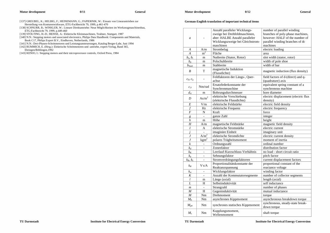
German-English translation of important technical items
a -
Anzahl paralleler Wicklungs-zweige bei Drehfeldmaschinen, aber: HALBE Anzahl paralleler Wicklungszweige bei Gleichstrom-maschinen
number of parallel winding branches of poly-phase machines, however: HALF of the number of parallel winding branches of dc machines
A A/m Strombelag electric loading A m2 Fläche area
bs, br m Nutbreite (Stator, Rotor) slot width (stator, rotor) bp m Polschuhbreite width of pole shoe
bStab m Stabbreite width of bar
B T magnetische Induktion (Flussdichte) magnetic induction (flux density)
cd, cq - Feldfaktoren der Längs-, Quer-achse
field factors of d-(direct) and q-(quadrature) axis
c Nm/rad Ersatzfederkonstante der Synchronmaschine
equivalent spring constant of a synchronous machine
dsi m Bohrungsdurchmesser bore diameter
D As/m2 elektrische Verschiebung (elektrische Flussdichte)
electric displacement (electric flux density)
E V/m elektrische Feldstärke electric field density f Hz elektrische Frequenz electric frequency F N Kraft force g - ganze Zahl integer h m Höhe height H A/m magnetische Feldstärke magnetic field density I A elektrische Stromstärke electric current j - imaginäre Einheit imaginary unit J A/m2 elektrische Stromdichte electric current density J kgm2 polares Trägheitsmoment moment of inertia k - Ordnungszahl ordinal number kd - Zonenfaktor distribution factor kK - Leerlauf-Kurzschluss-Verhältnis no load - short circuit ratio kp - Sehnungsfaktor pitch factor
kR, kL - Stromverdrängungsfaktoren current displacement factors
kR V.s/A Proportionalitätskonstante der Reaktanzspannung
proportional constant of the reactance voltage
kw - Wicklungsfaktor winding factor K - Anzahl der Kommutatorsegmente number of collector segments l m Länge (axial) length (axial) L H Selbstinduktivität self inductance m - Strangzahl number of phases M H Gegeninduktivität mutual inductance M Nm Drehmoment torque Mb Nm asynchrones Kippmoment asynchronous breakdown torque
Mp0 Nm synchrones statisches Kippmoment synchronous, steady-state break-down torque
Ms Nm Kupplungsmoment, Wellenmoment shaft torque
Motor development 0/13 General
TU Darmstadt Institute for Electrical Energy Conversion
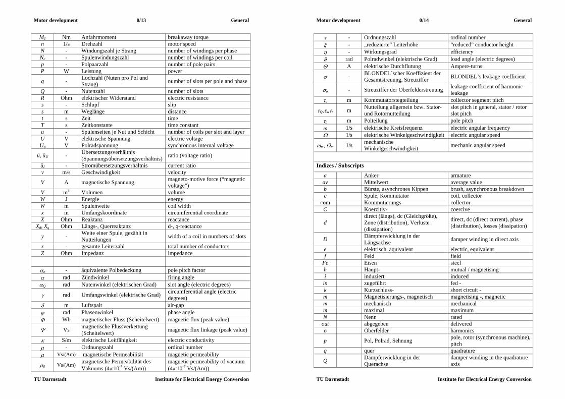
M1 Nm Anfahrmoment breakaway torque n 1/s Drehzahl motor speed N - Windungszahl je Strang number of windings per phase Nc - Spulenwindungszahl number of windings per coil p - Polpaarzahl number of pole pairs P W Leistung power
q - Lochzahl (Nuten pro Pol und Strang) number of slots per pole and phase
Q - Nutenzahl number of slots R Ohm elektrischer Widerstand electric resistance s - Schlupf slip s m Weglänge distance t s Zeit time T s Zeitkonstante time constant u - Spulenseiten je Nut und Schicht number of coils per slot and layer U V elektrische Spannung electric voltage Up V Polradspannung synchronous internal voltage
ü, üU - Übersetzungsverhältnis (Spannungsübersetzungsverhältnis) ratio (voltage ratio)
üI - Stromübersetzungsverhältnis current ratio v m/s Geschwindigkeit velocity
V A magnetische Spannung magneto-motive force (“magnetic voltage”)
V m3 Volumen volume W J Energie energy W m Spulenweite coil width x m Umfangskoordinate circumferential coordinate X Ohm Reaktanz reactance
Xd, Xq Ohm Längs-, Querreaktanz d-, q-reactance
y - Weite einer Spule, gezählt in Nutteilungen width of a coil in numbers of slots
z - gesamte Leiterzahl total number of conductors Z Ohm Impedanz impedance
e - äquivalente Polbedeckung pole pitch factor rad Zündwinkel firing angle Q rad Nutenwinkel (elektrischen Grad) slot angle (electric degrees)
rad Umfangswinkel (elektrische Grad) circumferential angle (electric degrees)
m Luftspalt air-gap rad Phasenwinkel phase angle Wb magnetischer Fluss (Scheitelwert) magnetic flux (peak value)
Vs magnetische Flussverkettung (Scheitelwert) magnetic flux linkage (peak value)
S/m elektrische Leitfähigkeit electric conductivity - Ordnungszahl ordinal number Vs/(Am) magnetische Permeabilität magnetic permeability
0 Vs/(Am) magnetische Permeabilität des Vakuums (4.10-7 Vs/(Am))
magnetic permeability of vacuum (4.10-7 Vs/(Am))
Motor development 0/14 General
TU Darmstadt Institute for Electrical Energy Conversion
- Ordnungszahl ordinal number - „reduzierte“ Leiterhöhe “reduced” conductor height - Wirkungsgrad efficiency rad Polradwinkel (elektrische Grad) load angle (electric degrees) A elektrische Durchflutung Ampere-turns
- BLONDEL´scher Koeffizient der Gesamtstreuung, Streuziffer BLONDEL’s leakage coefficient
o - Streuziffer der Oberfelderstreuung leakage coefficient of harmonic leakage
c m Kommutatorstegteilung collector segment pitch
Q,s,r m Nutteilung allgemein bzw. Stator- und Rotornutteilung
slot pitch in general, stator / rotor slot pitch
p m Polteilung pole pitch 1/s elektrische Kreisfrequenz electric angular frequency 1/s elektrische Winkelgeschwindigkeit electric angular speed
m, m 1/s mechanische Winkelgeschwindigkeit mechanic angular speed
Indizes / Subscripts
a Anker armature av Mittelwert average value b Bürste, asynchrones Kippen brush, asynchronous breakdown c Spule, Kommutator coil, collector
com Kommutierungs- collector C Koerzitiv- coercive
d direct (längs), dc (Gleichgröße), Zone (distribution), Verluste (dissipation)
direct, dc (direct current), phase (distribution), losses (dissipation)
D Dämpferwicklung in der Längsachse damper winding in direct axis
e elektrisch, äquivalent electric, equivalent f Feld field
Fe Eisen steel h Haupt- mutual / magnetising i induziert induced
in zugeführt fed - k Kurzschluss- short circuit - m Magnetisierungs-, magnetisch magnetising -, magnetic m mechanisch mechanical m maximal maximum N Nenn rated
out abgegeben delivered o Oberfelder harmonics
p Pol, Polrad, Sehnung pole, rotor (synchronous machine), pitch
q quer quadrature
Q Dämpferwicklung in der Querachse
damper winding in the quadrature axis
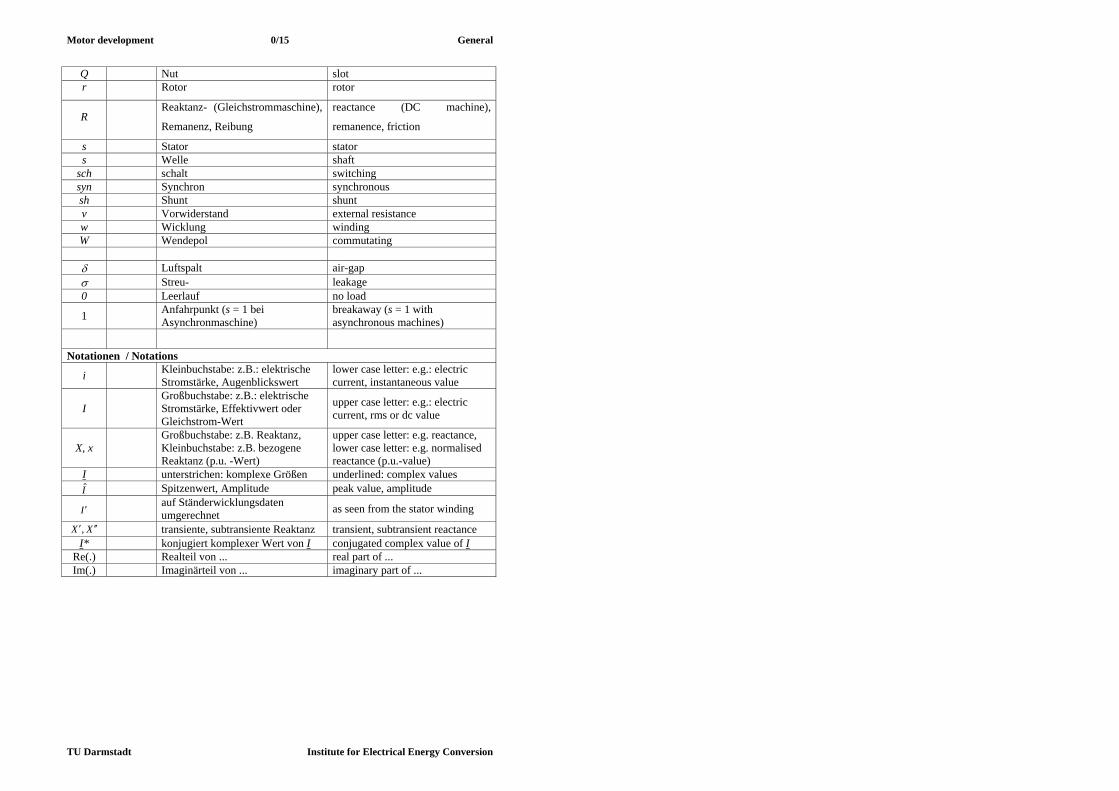
Motor development 0/15 General
TU Darmstadt Institute for Electrical Energy Conversion
Q Nut slot r Rotor rotor
R Reaktanz- (Gleichstrommaschine),
Remanenz, Reibung
reactance (DC machine),
remanence, friction
s Stator stator s Welle shaft
sch schalt switching syn Synchron synchronous sh Shunt shunt v Vorwiderstand external resistance w Wicklung winding W Wendepol commutating Luftspalt air-gap Streu- leakage 0 Leerlauf no load
1 Anfahrpunkt (s = 1 bei Asynchronmaschine)
breakaway (s = 1 with asynchronous machines)
Notationen / Notations
i Kleinbuchstabe: z.B.: elektrische Stromstärke, Augenblickswert
lower case letter: e.g.: electric current, instantaneous value
I Großbuchstabe: z.B.: elektrische Stromstärke, Effektivwert oder Gleichstrom-Wert
upper case letter: e.g.: electric current, rms or dc value
X, x Großbuchstabe: z.B. Reaktanz, Kleinbuchstabe: z.B. bezogene Reaktanz (p.u. -Wert)
upper case letter: e.g. reactance, lower case letter: e.g. normalised reactance (p.u.-value)
I unterstrichen: komplexe Größen underlined: complex values I Spitzenwert, Amplitude peak value, amplitude
I auf Ständerwicklungsdaten umgerechnet as seen from the stator winding
XX , transiente, subtransiente Reaktanz transient, subtransient reactance I* konjugiert komplexer Wert von I conjugated complex value of I
Re(.) Realteil von ... real part of ... Im(.) Imaginärteil von ... imaginary part of ...

Motor development 1/1 Permanent magnet machines
TU Darmstadt Institute for Electrical Energy Conversion
1. Permanent magnet synchronous machines as “brushless DC drives” 1.1 Basic principle of brushless DC drives
Fig. 1.1-1: Cross section of six-pole PM Fig. 1.1-2: Robot with four degrees of freedom synchronous machine (Siemens AG) (axes A1, A2, A3, A6) for loading goods: 160 kg
lifting force, 1200 cycles per hour (=3 s per cycle), continuous operation. Brushless DC drives visible on the sides of the axes joints (ABB, Sweden).
a) b) Fig. 1.1-3: Tooling machines for milling with main drive (usually AC induction motor or PM synchronous drive) and a) 3 and b) 2 brushless DC servo drives for positioning the tool (Siemens AG). Synchronous machines, fed by PWM inverters, which allow field oriented motor control, behave like DC machines and not like line-fed synchronous machines. No pull-out torque exists and no oscillation of rotor. The inverter acts like the commutator of the DC machine, the stator three-phase AC winding like the DC armature winding of the DC rotor and the magnetostatically excited rotor of the synchronous machine corresponds with the magneto-statically excited DC stator. Therefore this kind of synchronous machine is called "brushless DC drive", as – unlike in DC machines - no brushes are necessary. Usually a rotor position sensor is used to determine rotor flux orientation, which is necessary for field oriented control. Permanent magnet rotor excitation allows rotor flux generation without any excitation losses, thus gaining high efficiency and low temperature rise. Stator PWM voltage generates three phase AC current system in stator winding, the coils of which are distributed
Motor development 1/2 Permanent magnet machines
TU Darmstadt Institute for Electrical Energy Conversion
in stator slots. These AC winding currents with a time shift of one third of a period between each two currents generate along with the distributed three-phase winding a travelling air gap magnetic field, which drags the rotors synchronously. Fig.1.1-1 shows the cross section of a typical three phase, six-pole PM synchronous motor with rare earth rotor permanent magnets, 36 stator slots and q = 2 slots per pole and phase. These brushless DC drives are widely used, such as robot drives (Fig.1.1-2) or in tooling machines (Fig.1.1-3 a, b). Their features are low torque ripple (typically below 2 %) for smooth movements at low speed ("servo drive function"), high overload capability for fast acceleration (typically 4-times overload for short period of time e.g. a few seconds), no additional cooling system ("self cooling") and high degree of protection ("totally enclosed machine"). 1.1.1 Basic function of PM synchronous machine A magnetic field H is excited along a closed loop C in empty space according to Ampere´s law (1.1.1-1) by the enclosed ampere-turns IN , where I is the electric current and N is the number of turns in series of the electric conductor.
C
INsdH (1.1.1-1)
Fig.1.1.1-1 shows an example where two different conductors with two different currents I1 and I2 form the total ampere-turns. The so-called magnetic flux density B is proportional to the field strength H.
700 104 HB Vs/(Am) (1.1.1-2)
Fig.1.1.1-1: Ampere´s law: A magnetic field H is excited along a closed loop C in empty space by the enclosed ampere-turns . In this example two different conductors with two different currents I1 and I2 form the total ampere-turns (A. Prechtl, Springer, Wien). In Fig.1.1.1-2 is shown one phase, called U, of a distributed winding with q = 3 coils in series per pole and phase. The coil sides are placed in slots, the connection of coil sides by winding overhangs is not depicted. If the coils are excited by a current, according to (1.1.1-1) a field is excited, which generates a magnetic flux. As the magnetic flux per pole penetrates iron parts and air gap, the flux density in the air gap and in the iron is determined by the geometric cross sections A, AFe, where the flux passes by.

Motor development 1/3 Permanent magnet machines
TU Darmstadt Institute for Electrical Energy Conversion
FeFe ABAB /,/ (1.1.1-3) With material law for air and iron
FeFeFe HBHB ,0 (1.1.1-4) we get the magnetic field strength, which is determined by Ampere´s law (1.1.1-1). With
70 104 Vs/(Am) and assuming instead of real ratio 5000...2000/ 0 Fe in
unsaturated state the theoretically ideal iron with Fe the magnetic field strength HFe in the iron parts is zero.
0/ FeFeFe BH (1.1.1-5) From Ampere´s law for a closed flux line C around a stator slot (with its ampere-turns Q), which contains the sections and sFe in air gap and iron parts, thus crossing the air gap from stator (subscript s) to rotor (subscript r) we get
QC
leftrightrFerFesFesFe HHsHsHsdH ,,,,,,
. (1.1.1-6)
The values leftright HH ,, , denote the field strength left and right of one slot in the air gap. With HFe = 0 and the “magnetic voltage” (“magnetmotive force” MMF) for air gap
HV (1.1.1-7) the air gap flux density B is directly proportional to MMF:
/0VB . (1.1.1-6)
Fig. 1.1.1-2: Generation of flux lines by distributed winding system (here only one phase U depicted, q = 3, Nc turns per coil, aa parallel coil groups, so current in one coil is i/aa) In Fig.1.1.1-3 for a distributed three-phase winding with q = 2 slots per pole and phase the slot ampere turn distribution is shown for time steps t = 0, t = T/12 and t = T/6, where T = 1/fs is the AC current period with fs stator frequency of AC sinusoidal currents. Defining positive direction of H from stator to rotor, and applying (1.1.1-6) to each slot along co-ordinate x, the MMF distribution in air gap is
Motor development 1/4 Permanent magnet machines
TU Darmstadt Institute for Electrical Energy Conversion
)()(,, xxVHHsdH QC
leftright
. (1.1.1-9)
Starting at an arbitrary position x, where H is zero, a step-like MMF distribution is generated by the distributed winding. At each slot the MMF distribution changes according to the local slot ampere turns Q, stepping up, if Q > 0, and stepping down, if Q < 0. Slot width is neglected, therefore the change of stator field at the slot ampere turns is stepwise with step height proportional to instantaneous slot ampere turns. According to (1.1.1-8) the MMF distribution coincides with air gap flux density distribution B, as long as Fe . Thus the air gap field B is a step-like function of circumference co-ordinate x.
Fig. 1.1.1-3: Generation of travelling air gap field by sinusoidal three phase current system (q = 2) Regarding the time steps t = 0, t = T/12 and t = T/6, one recognizes that the air gap flux density distribution B is travelling to the left with the speed pssyn fv 2 . It may be shown by Fourier analysis of this flux density distribution, that the fundamental space harmonic, which is sinusoidally distributed, keeps its shape unchanged during travelling,

Motor development 1/5 Permanent magnet machines
TU Darmstadt Institute for Electrical Energy Conversion
whereas the step-like flux density distribution changes shape during travelling, as can be seen from Fig.1.1.1-2. Speed of this fundamental travelling sine wave is also
pssyn fv 2 , (1.1.1-10) where pole pitch p is half of the wave length of this fundamental sine wave. In rotational machines this velocity is the wave surface velocity at the stator bore, therefore rotational speed of this fundamental wave is
pfn s
syn . (1.1.1-11)
This stator travelling wave acts on the rotor magnets with a magnetic dragging force, this moving the permanent magnet rotor synchronously with the same speed n = nsyn. Thus the machine is acting as a motor. If the rotor is turned by external source, it will induce in the stator winding a voltage due to the moving rotor magnets, thus causing a changing flux linkage of stator coils. This induced voltage up may generate a current in the stator loaded winding; - the machine is in generating mode (generator). Conclusions: A three-phase winding with distributed coils with their coil sides placed in slots is called distributed winding. When fed with current, this distributed winding excites a step-like air gap flux density distribution with north and south poles. Width of the poles is called pole pitch. The fundamental harmonic of this step-like distribution has wavelength equal to two pole pitches. If the coils of the three phases U, V, W of the distributed winding are spaced by
3/2 p and are fed by sinusoidal three-phase current with 3/2 phase shift, the air gap flux density is travelling (rotating) with synchronous speed. 1.1.2. Permanent magnet technology a) Permanent magnet properties: The elements Fe, Ni and Co show ferromagnetic behaviour, that means they consist of randomly distributed elementary permanently magnetized regions. If these elements are exposed to an external magnetic field H, these “elementary” magnets turn parallel to this external field and create an own magnetic polarization J. This polarization amplifies the external field, yielding a resulting magnetic flux density
JHB 0 . (1.1.2-1) Permanent magnets always consist of these elements Fe, Ni or Co and other elements, which are necessary to increase coercive field. The most widely used permanent magnet materials are - AlNiCo, - Ba-Ferrite and Sr-Ferrite, - Rare earth magnets SmCo and NdFeB. Magnetization of rare earth permanent magnetic material in external field HM is shown in Fig.1.1.2-1 along the dotted “virgin” curve. When all “elementary” magnets are in parallel
Motor development 1/6 Permanent magnet machines
TU Darmstadt Institute for Electrical Energy Conversion
with the external field, the maximum value JM = Js, the so-called saturation of polarization, is reached. The corresponding necessary flux density
ssM JHB 0 (1.1.2-2) is huge (about 3.5 T ... 4 T). When the external field is switched off, J decreases along the upper branch of the closed JM(HM) loop and reaches JM(HM=0) = JR = BR, the so-called remanence flux density. With inverse field H the permanent magnet is demagnetized completely at HCJ. At the coercive field strength HCB the resulting flux density BM vanishes.
Fig.1.1.2-1: Hysteresis loop JM(HM) and BM(HM) of a rare earth permanent magnet The inclination of the BM(HM)-loop is ca. 1.05 0 according to (1.1.2-1). Therefore modern rare earth magnets behave in an external magnetic field like air with a relative permeability of nearly unity. b) Design of magnet dimensions: In permanent magnet motors the magnets are often fixed on the rotor surface (Fig.1.1-1). The air gap between stator and rotor and the stator and rotor iron have to be magnetized by the magnets. Let us assume that the iron permeability is infinite ( Fe ), then according to
FeFeFe HB and a given flux density the iron magnetic field HFe is zero. Thus Ampere´s law yields for the resulting magnetic field of the surface mounted magnets with magnet height hM according to Fig.1.1.2-2 with C as the closed loop of the B flux lines:
Fig.1.1.2-2: Magnet field of surface mounted permanent magnet (no electric current in stator winding)
Motor development 1/7 Permanent magnet machines
TU Darmstadt Institute for Electrical Energy Conversion
0)(2 MMC
hHHsdH (1.1.2-2)
As the magnetic flux of the magnets has to be constant in the machine and the cross section of flux in air gap and in the magnets is the same AM = A , one gets ABAB MM (1.1.2-3) and therefore BM = B . With (1.1.2-2) the relation between the air gap flux density and field strength within the magnet is
MMM BHhHB
00 . (1.1.2-4)
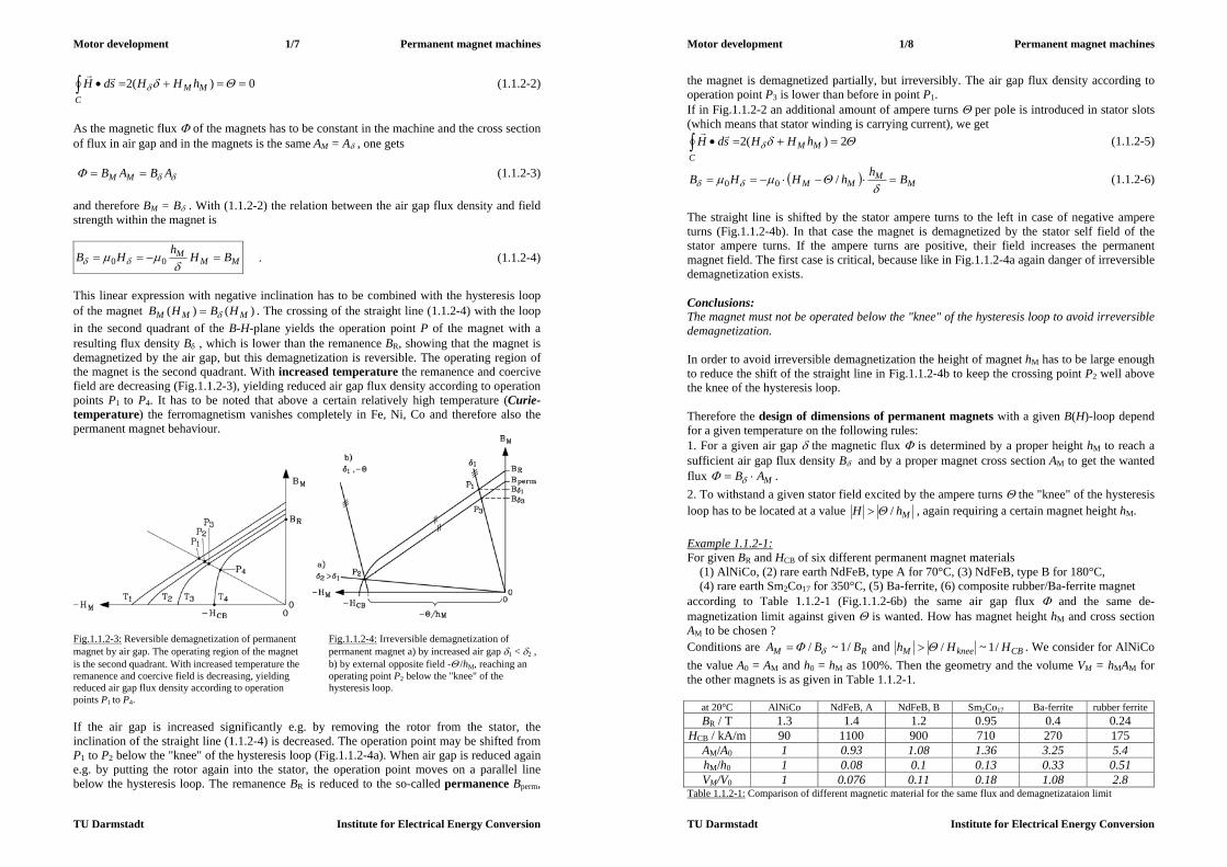
This linear expression with negative inclination has to be combined with the hysteresis loop of the magnet )()( MMM HBHB . The crossing of the straight line (1.1.2-4) with the loop in the second quadrant of the B-H-plane yields the operation point P of the magnet with a resulting flux density B , which is lower than the remanence BR, showing that the magnet is demagnetized by the air gap, but this demagnetization is reversible. The operating region of the magnet is the second quadrant. With increased temperature the remanence and coercive field are decreasing (Fig.1.1.2-3), yielding reduced air gap flux density according to operation points P1 to P4. It has to be noted that above a certain relatively high temperature (Curie-temperature) the ferromagnetism vanishes completely in Fe, Ni, Co and therefore also the permanent magnet behaviour.
Fig.1.1.2-3: Reversible demagnetization of permanent Fig.1.1.2-4: Irreversible demagnetization of magnet by air gap. The operating region of the magnet permanent magnet a) by increased air gap 1 < 2 , is the second quadrant. With increased temperature the b) by external opposite field - /hM, reaching an remanence and coercive field is decreasing, yielding operating point P2 below the "knee" of the reduced air gap flux density according to operation hysteresis loop. points P1 to P4. If the air gap is increased significantly e.g. by removing the rotor from the stator, the inclination of the straight line (1.1.2-4) is decreased. The operation point may be shifted from P1 to P2 below the "knee" of the hysteresis loop (Fig.1.1.2-4a). When air gap is reduced again e.g. by putting the rotor again into the stator, the operation point moves on a parallel line below the hysteresis loop. The remanence BR is reduced to the so-called permanence Bperm,
Motor development 1/8 Permanent magnet machines
TU Darmstadt Institute for Electrical Energy Conversion
the magnet is demagnetized partially, but irreversibly. The air gap flux density according to operation point P3 is lower than before in point P1. If in Fig.1.1.2-2 an additional amount of ampere turns per pole is introduced in stator slots (which means that stator winding is carrying current), we get
2)(2 MMC
hHHsdH (1.1.2-5)
MM
MM BhhHHB
/00 (1.1.2-6)
The straight line is shifted by the stator ampere turns to the left in case of negative ampere turns (Fig.1.1.2-4b). In that case the magnet is demagnetized by the stator self field of the stator ampere turns. If the ampere turns are positive, their field increases the permanent magnet field. The first case is critical, because like in Fig.1.1.2-4a again danger of irreversible demagnetization exists. Conclusions: The magnet must not be operated below the "knee" of the hysteresis loop to avoid irreversible demagnetization. In order to avoid irreversible demagnetization the height of magnet hM has to be large enough to reduce the shift of the straight line in Fig.1.1.2-4b to keep the crossing point P2 well above the knee of the hysteresis loop. Therefore the design of dimensions of permanent magnets with a given B(H)-loop depend for a given temperature on the following rules: 1. For a given air gap the magnetic flux is determined by a proper height hM to reach a sufficient air gap flux density B and by a proper magnet cross section AM to get the wanted flux MAB . 2. To withstand a given stator field excited by the ampere turns the "knee" of the hysteresis loop has to be located at a value MhH / , again requiring a certain magnet height hM. Example 1.1.2-1: For given BR and HCB of six different permanent magnet materials (1) AlNiCo, (2) rare earth NdFeB, type A for 70°C, (3) NdFeB, type B for 180°C, (4) rare earth Sm2Co17 for 350°C, (5) Ba-ferrite, (6) composite rubber/Ba-ferrite magnet according to Table 1.1.2-1 (Fig.1.1.2-6b) the same air gap flux and the same de-magnetization limit against given is wanted. How has magnet height hM and cross section AM to be chosen ? Conditions are RM BBA /1~/ and CBkneeM HHh /1~/ . We consider for AlNiCo the value A0 = AM and h0 = hM as 100%. Then the geometry and the volume VM = hMAM for the other magnets is as given in Table 1.1.2-1.
at 20°C AlNiCo NdFeB, A NdFeB, B Sm2Co17 Ba-ferrite rubber ferrite BR / T 1.3 1.4 1.2 0.95 0.4 0.24
HCB / kA/m 90 1100 900 710 270 175 AM/A0 1 0.93 1.08 1.36 3.25 5.4 hM/h0 1 0.08 0.1 0.13 0.33 0.51 VM/V0 1 0.076 0.11 0.18 1.08 2.8
Table 1.1.2-1: Comparison of different magnetic material for the same flux and demagnetizataion limit

Motor development 1/9 Permanent magnet machines
TU Darmstadt Institute for Electrical Energy Conversion
Conclusions: Rare earth magnets allow for the same flux and the same demagnetization limit a much smaller magnetic volume of only about 10%, which yields compact PM motors, but it is expensive. Cheap PM motors with ferrite magnets need nearly the same amount of magnets as AlNiCo. Motors with AlNiCo need relatively long magnets, whereas ferrite magnets without flux concentration methods have a rather low air gap flux density below 0.4 T.
Fig.1.1.2-5: Comparison of influence of material properties on magnetic design for (1) AlNiCo, (2) rare earth NdFeB, type A for 70°C, (3) NdFeB, type B for 180°C, (4) Sm2Co17, (5) Ba-ferrite, (6) composite rubber-ferrite Example 1.1.2-2: Magnetic B(H)-loops for (Fig.1.1.2-6) a) 1: Soft magnetic material (e.g. iron) compared with 2: permanent magnet characteristic b) Second quadrant for permanent magnets: (1) AlNiCo, (2) anisotropic Ba-ferrite, (3) rare
earth magnet Sm2Co17 (for 350°C), (4) rare earth magnet NdFeB (for 180°C)
a) b) Fig.1.1.2-6: B(H)-characteristics: a) (1) Soft magnetic material, (2) PM magnet, (b) PM magnets: Second quadrant at 20°C; (1) Al-Ni-Co, (2): Ba-Ferrit, (3): Sm2Co17 (max = 350°C) (4): NdFeB (max = 180°C) c) Surface-mounted permanent magnets on rotors:
Motor development 1/10 Permanent magnet machines
TU Darmstadt Institute for Electrical Energy Conversion
a) b) Fig.1.1.2-7: No-load air gap magnetic flux density a) with pole coverage ratio e = 1, and b) with e < 1 The no-load condition of an electric machine means that stator current is zero. Rotor magnets produce a rectangular shaped magnetic flux density profile (Fig.1.1.2-7a) with an amplitude given by (1.1.2-4). If some magnets are omitted, the pole coverage ratio is e < 1; thus a pole gap exists (Fig.1.1.2-7b). Under load, the feeding inverter impresses a stator current distribution, which should yield maximum torque for a given current amplitude. According to the electromagnetic Lorentz-force Fc on a current-carrying conductor (current I) with length l
l
c BsdIF0
)(
(1.1.2-7)
we get for right angle between straight conductor and constant flux density vector B
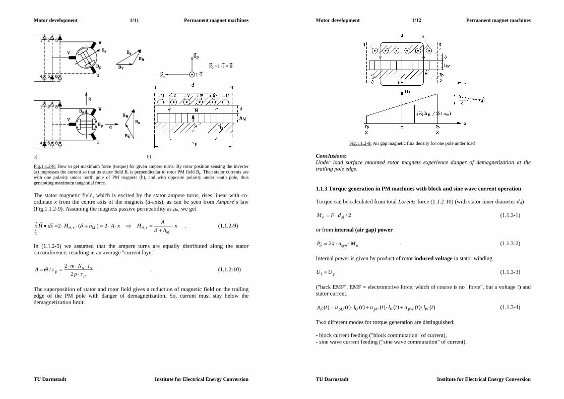
lBIFc . (1.1.2-8) Thus for maximum force cFF (and therefore maximum torque) of all current-carrying conductors in stator winding the currents of the three phases must flow per pole in the same direction to add to a total resulting force. For a three-phase winding this is achieved by moving the stator travelling field synchronously with rotor magnets and keeping the rotor position relative to the stator travelling field so, that positive ampere turns are opposite of rotor north pole and negative ampere turns are opposite of rotor south pole. Therefore a rotor position sensor is necessary to tell the inverter the appropriate current phase angle for impressing stator current. In Fig.1.1.2-8 the current distribution for maximum torque is shown along with force generation.
Motor development 1/11 Permanent magnet machines
TU Darmstadt Institute for Electrical Energy Conversion
a) b) Fig.1.1.2-8: How to get maximum force (torque) for given ampere turns: By rotor position sensing the inverter (a) impresses the current so that its stator field Bs is perpendicular to rotor PM field Bp. Then stator currents are with one polarity under north pole of PM magnets (b), and with opposite polarity under south pole, thus generating maximum tangential force. The stator magnetic field, which is excited by the stator ampere turns, rises linear with co-ordinate x from the centre axis of the magnets (d-axis), as can be seen from Ampere´s law (Fig.1.1.2-9). Assuming the magnets passive permeability as 0, we get
xh
AHxAhHsdHM
sMsC
,, 2)(2
. (1.1.2-9)
In (1.1.2-5) we assumed that the ampere turns are equally distributed along the stator circumference, resulting in an average "current layer"
p
ssp p
INmA
22/ . (1.1.2-10)
The superposition of stator and rotor field gives a reduction of magnetic field on the trailing edge of the PM pole with danger of demagnetization. So, current must stay below the demagnetization limit.
Motor development 1/12 Permanent magnet machines
TU Darmstadt Institute for Electrical Energy Conversion
Fig.1.1.2-9: Air gap magnetic flux density for one pole under load Conclusions: Under load surface mounted rotor magnets experience danger of demagnetization at the trailing pole edge. 1.1.3 Torque generation in PM machines with block and sine wave current operation Torque can be calculated from total Lorentz-force (1.1.2-10) (with stator inner diameter dsi)
2/sie dFM (1.1.3-1) or from internal (air gap) power
esyn MnP 2 . (1.1.3-2) Internal power is given by product of rotor induced voltage in stator winding
pi UU (1.1.3-3) ("back EMF", EMF = electromotive force, which of course is no "force", but a voltage !) and stator current.
)()()()()()()( titutitutitutp WpWVpVUpU (1.1.3-4) Two different modes for torque generation are distinguished: - block current feeding ("block commutation" of current), - sine wave current feeding ("sine wave commutation" of current).

Motor development 1/13 Permanent magnet machines
TU Darmstadt Institute for Electrical Energy Conversion
a) (Siemens AG, Germany) b) Fig.1.1.3-1: Block current feeding: a) Cross section of PM synchronous machine with 100% pole coverage ratio, b) trapezoidal no-load stator phase voltage (back EMF); block shaped current impressed in phase with back EMF With block current feeding the rotor has surface mounted magnets with 100% pole coverage ratio, yielding rectangular shaped air gap magnetic flux density. This distribution yields trapezoidal no-load stator induced voltage (back EMF, Fig.1.1.3-1), when stator slots or rotor magnets are skewed by one stator slot pitch. For this purpose, the stator winding consists of coils with coil span W equal to pole pitch p. Therefore, simple single layer three phase winding can be used. If block stator currents are impressed by inverter with 120° pulse width and 60° gap in phase with back EMF, the internal power according to (1.1.3-4) is contributed at each moment by only two of the three phases. The third phase always yields zero power (Fig. 1.1.3-2). Usually stator winding for inverter operation is star-connected. With phase current block amplitude I and phase back EMF amplitude pU torque amplitude is
nIU
M pe
2
ˆˆ2 . (1.1.3-5)
Motor development 1/14 Permanent magnet machines
TU Darmstadt Institute for Electrical Energy Conversion
Fig.1.1.3-2: Torque generation with block current feeding, calculated via internal power. A smooth torque without any ripple is theoretically produced with contribution of two phases at each moment With sine wave current feeding the rotor has surface mounted magnets with typically 85% pole coverage ratio, yielding 85%-block shaped air gap magnetic flux density with gaps of 15% in between. If a two-layer star-connected chorded winding with coil span W < p is used with number of coils per pole and phase q > 1 is used, the induced no-load voltage is nearly sinusoidal (Fig.1.1.3-3). If sine wave stator currents are impressed by inverter in phase with this sinusoidal back EMF, the internal power according to (1.1.3-4) is constant for each moment. Each phase contributes one third of the total power.
Fig.1.1.3-3: Torque generation with sine wave current feeding: Sinusoidal phase current is impressed by inverter in phase with sinusoidal back EMF, resulting in pulsating power per phase, but smooth constant power and torque for all three phases.
Motor development 1/15 Permanent magnet machines
TU Darmstadt Institute for Electrical Energy Conversion
)3/4cos(ˆ)3/4cos(ˆ)3/2cos(ˆ)3/2cos(ˆ)cos(ˆ)cos(ˆ)(
tItU
tItUtItUtp
p
pp (1.1.3-6)
By use of
)cos()cos(21coscos
we get
1)
382cos(
2
ˆˆ1)
342cos(
2
ˆˆ1)2cos(
2
ˆˆ)( t
IUt
IUt
IUtp ppp
and with
0)3
8cos()3
4cos()cos(
finally the time-independent internal power (m = 3: number of phases)
.2
ˆˆ)( const
IUmtp p (1.1.3-7)
and the electromagnetic torque
nIU
M pe
2
ˆˆ)2/3( . (1.1.3-8)
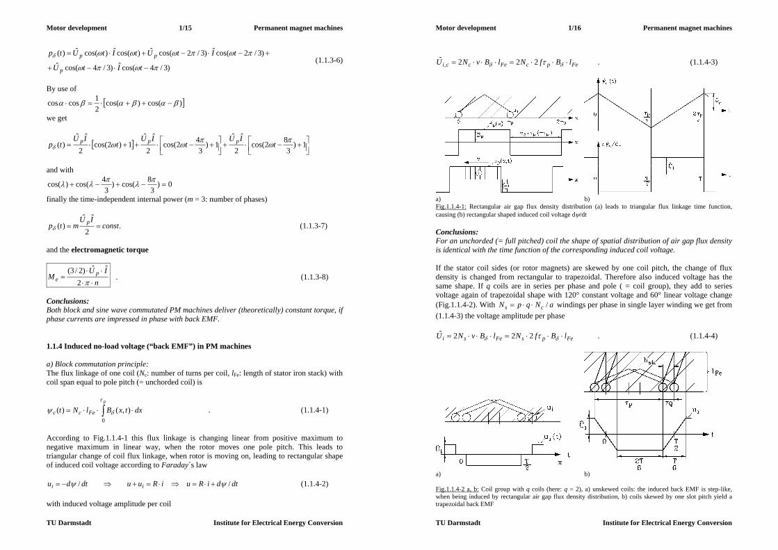
Conclusions: Both block and sine wave commutated PM machines deliver (theoretically) constant torque, if phase currents are impressed in phase with back EMF. 1.1.4 Induced no-load voltage (“back EMF”) in PM machines a) Block commutation principle: The flux linkage of one coil (Nc: number of turns per coil, lFe: length of stator iron stack) with coil span equal to pole pitch (= unchorded coil) is
dxtxBlNtp
Fecc
0
),()( . (1.1.4-1)
According to Fig.1.1.4-1 this flux linkage is changing linear from positive maximum to negative maximum in linear way, when the rotor moves one pole pitch. This leads to triangular change of coil flux linkage, when rotor is moving on, leading to rectangular shape of induced coil voltage according to Faraday´s law
dtdiRuiRuudtdu ii // (1.1.4-2) with induced voltage amplitude per coil
Motor development 1/16 Permanent magnet machines
TU Darmstadt Institute for Electrical Energy Conversion
FepcFecci lBfNlBvNU 222ˆ, . (1.1.4-3)
a) b) Fig.1.1.4-1: Rectangular air gap flux density distribution (a) leads to triangular flux linkage time function, causing (b) rectangular shaped induced coil voltage d/dt Conclusions: For an unchorded (= full pitched) coil the shape of spatial distribution of air gap flux density is identical with the time function of the corresponding induced coil voltage. If the stator coil sides (or rotor magnets) are skewed by one coil pitch, the change of flux density is changed from rectangular to trapezoidal. Therefore also induced voltage has the same shape. If q coils are in series per phase and pole ( = coil group), they add to series voltage again of trapezoidal shape with 120° constant voltage and 60° linear voltage change (Fig.1.1.4-2). With aNqpN cs / windings per phase in single layer winding we get from (1.1.4-3) the voltage amplitude per phase
FepsFesi lBfNlBvNU 222ˆ . (1.1.4-4)
a) b) Fig.1.1.4-2 a, b: Coil group with q coils (here: q = 2), a) unskewed coils: the induced back EMF is step-like, when being induced by rectangular air gap flux density distribution, b) coils skewed by one slot pitch yield a trapezoidal back EMF

Motor development 1/17 Permanent magnet machines
TU Darmstadt Institute for Electrical Energy Conversion
c) Fig.1.1.4-2c: Coil group with q = 3 coils: unskewed coils: the induced back EMF is step-like, but coils - skewed by one slot pitch - yield a trapezoidal back EMF b) Sine wave commutation principle:
Fig.1.1.4-3: Influence of e on the rotor flux density amplitudes: At e = 0.85 the fundamental amplitude is reduced by 3%, but 5th and 7th harmonic are reduced drastically. The air gap flux density distribution – depending on rotor co-ordinate xr - may be expanded into a Fourier-series with only odd ordinal numbers due to the symmetry of north and south pole
1, )/cos()(
prr xBxB , ...,7,5,3,1 (1.1.4-5)
Motor development 1/18 Permanent magnet machines
TU Darmstadt Institute for Electrical Energy Conversion
with amplitudes
)2/sin(4,
eBB . (1.1.4-6)
In Fig.1.1.4-3 the influence of e on the amplitudes shows, that at e = 0.85 the fundamental amplitude is reduced by 3%, but 5th and 7th harmonic are reduced considerably. With moving rotor the relationship between stator and rotor co-ordinate x = xs and xr is
tfxtvxx prsynrs 2 (1.1.4-7) and therefore
)cos(),( ,, txBtxBp
, = 1, 3, 5, 7, ... . (1.1.4-8)
If the coil span is smaller than one pole pitch, the coil flux linkage of the remaining 5th and 7th harmonic can be further reduced, if the ratio pW / is chosen appropriately. With (1.1.4.-1) and (1.1.4-3) we get
2/
2/, )cos()
2sin(2),()(
W
W pFe
pcFecc tWBlNdxtxBlNt
. (1.1.4-9)
Compared with unchorded coil W = p, we get a reduction of flux linkage by the pitch factor
)2
sin(
p
pWk . (1.1.4-10)
Example 1.1.4-1: Three-phase winding with 6 slots per pole, thus q = 2 slots per pole and phase. Coil span reduced by one slot pitch, resulting in W /p = 5/6. Reduction of flux linkage is very strong for 5th and 7th harmonic.
1 3 5 7 9 11 13 kp 0.966 -0.707 0.259 0.259 -0.707 0.966 0.966
Table 1.1.4-1: Reduction of coil flux linkage due to chording W /p = 5/6. So harmonics with higher ordinal number will induce stator voltage with increased frequency f, but can be reduced by appropriate chording. A further reduction of these higher harmonics occurs due to the fact, that with q > 1 several coils per pole and phase are connected in series. There is a phase shift Q between the voltages of adjacent coils due the coil displacement by the slot pitch Q, which increases with increasing ordinal number.
)/( pQQ (1.1.4-11) Therefore the resulting series voltage of the coil group is smaller than the algebraic sum of voltage per coil.

Motor development 1/19 Permanent magnet machines
TU Darmstadt Institute for Electrical Energy Conversion
Example 1.1.4-2: Three-phase winding, 9 slots per pole, q = 3 coils per pole and phase.
209/1809/)/(1 pQQQ
Fig.1.1.4-4: The resulting series voltage ugr of the coil group with q = 3 coils is smaller than the algebraic sum of voltage per coil uc. The ratio of resulting series voltage ,,griU versus algebraic sum of coil voltages ,,ciU is according to Fig.1.1.4-4 the so-called distribution factor kd,:
mqq
m
q
q
UqU
kQ
Q
ci
grid
2sin
2sin
2sin2
2sin2
ˆˆ
,
,
,,
,,,
(1.1.4-12)
1 3 5 7 9 11 13
kd 0.960 0.667 0.218 -0.177 -0.333 -0.177 0.218 Table 1.1.4-2: Reduction of coil flux linkage due to coil group arrangement q = 3. So, the resulting effect of harmonics, decreasing with ordinal number, and of chording and coil group arrangement, being summarized in the winding factor
,,, dpw kkk , (1.1.4-13) can be given for the induced voltage with (1.1.4-2) as
)sin()sin(2)( tUtBlkNtu iFep
wsi
, (1.1.4-14)
where aNqpN cs /2 is the number of windings per phase of two-layer winding. If the stator winding is star connected, the third harmonic voltages in all three phases U, V, W are IN phase and IDENTICAL:
)()3cos())3/4(3cos()()()3cos())3/2(3cos()(
)3cos()(
3333
3333
33
tutUtUtututUtUtu
tUtu
UW
UV
U
(1.1.4-15)
Motor development 1/20 Permanent magnet machines
TU Darmstadt Institute for Electrical Energy Conversion
Therefore the line-to-line voltages show NO 3rd harmonic component: 0)()()()()( 33333 tututututu UUVUUV
and so on for all phases. Further, no current of 3rd harmonic can occur, as according to Ohm´s law the current per phase is proportional to the phase impedance Z3 and phase voltage U3 and according to Kirchhoff´s second law the sum of all currents in the star node must be zero.
003/ 33333333 IIIIIZUI WVU (1.1.4-16) Thus, by star connection, the 3rd current harmonic and all other current harmonics with ordinal numbers, divisible by factor 3, and all corresponding line-to-line voltages are suppressed. So, the ordinal numbers 3, 9, 15, ... vanish. In addition, skewing by the distance bsk reduces flux linkage and therefore induced voltage further by the so-called skewing factor (which is not derived here)
p
skbSSS
2/)sin( . (1.1.4-17)
Example 1.1.4-3: Six pole machine, rotor speed 1500/min Stator: Three-phase winding, 5/6 chorded coils, q = 2 coils per pole and phase Rotor: Surface permanent magnets, 85% pole coverage ratio
Magnets skewed by one stator slot pitch 15122
p
skb
Ordinal Number
Stator frequency
Flux density
Winding Factor
Skewing factor
Induced phase
voltage
Induced line-line voltage
f B kw skew, Ui Ui,LL 1 75 Hz 100 % 0.933 0.989 100 % 100 % 3 225 Hz -26.1 % -0.50 0.900 12.73 % 0 5 375 Hz 7.9 % 0.067 0.738 0.42 % 0.42 % 7 525 Hz 1.2 % -0.067 0.527 0.05 % 0.05 % 9 675 Hz -6.0 % 0.50 0.300 0.98 % 0 11 825 Hz 8.0 % -0.933 0.090 0.73 % 0.73 %
Table 1.1.4-3: Spectrum of induced voltages for six pole machine, rotor speed 1500/min, three-phase winding, 5/6 chorded coils, q = 2 coils per pole and phase, 85% pole coverage ratio, skew one slot pitch Table 1.1.4-3 shows that the amplitudes of induced voltages of higher harmonics are below of 1 % of fundamental voltage and can therefore be neglected. Conclusions: Due to pole coverage ratio less than unity, chording of coils, arrangement of coils in coil groups, skewing of coils and star connection the back EMF is nearly sinusoidal, although air gap flux density is not. Example 1.1.4-4: Motor designed for sine wave commutation: Measured no-load voltage in generator mode (back EMF), machine driven by external motor (Fig.1.1.4-5). The back EMF (no-load voltage) is nearly sinusoidal due to “filter effect” of stator winding, although the rotor has

Motor development 1/21 Permanent magnet machines
TU Darmstadt Institute for Electrical Energy Conversion
surface mounted magnets with 85% pole coverage. Fourier analysis shows that higher harmonics (here: 5th order: f = 5fs = 167 Hz) are very small, compared with fundamental fs = 33.5 Hz.
Fig.1.1.4-5: Measured no-load voltage line-to-line of a 4 pole brushless DC motor, designed for sine wave commutation, at 1000/min, showing nearly ideal sine wave back EMF (Data: MN = 1.3 Nm, nN = 6000/min) Fourier-Analysis of no-load voltage: = 1: 33.5 Hz, 74.8 V = 5: 167 Hz, 0.34 V Other amplitudes are negligible ! 1.1.5 Equivalent circuit of PM synchronous machine
Fig.1.1.5-1: Distributed stator winding excites air gap flux density. Fundamental of this flux density induces back into stator winding, thus linking phases U, V, W, generating a self- inductance Lh, which is equal for all three phases (here is shown flux linkage with coil of phase U) The stator field Bs – excited by the stator currents – contains a fundamental sine wave, which can be easily calculated with (1.1.5-2), if a constant magnetically active air gap res is assumed. With surface mounted magnets we get this magnetically active air gap as the sum of mechanical air gap , bandage height hB and the height of magnets hM, as modern rare earth magnets behave in an external magnetic field like air with a relative permeability of nearly unity.
MBres hh (1.1.5-1) Sine wave amplitude Bs,1 of stator field for stator current Is (rms):
pIkNmB swsss
ress
20
1, . (1.1.5-2)
Motor development 1/22 Permanent magnet machines
TU Darmstadt Institute for Electrical Energy Conversion
The flux per pole is
1,2
sFep Bl
, (1.1.5-3)
yielding a self-induced voltage per phase
wss
sss kNU
2, , (1.1.5-4)
which can be expressed by the main inductance
res
Fepswss
ss
ssh
l
pmkN
IU
L
2
20
, 2)( . (1.1.5-5)
a) b) Fig.1.1.5-2: Schematic drawing of stray flux lines: a) Slot leakage flux, rising linear from bottom to top of slot according to Ampere´s law, b) leakage flux density of winding overhangs Additional stray flux in the slots LQ and in the winding overhangs Lb (Fig.1.1.5-2) and the self-inductance of the higher Fourier harmonics Lo of the step-like air gap flux density distribution have to be considered in addition as so called stray (or leakage) inductance L = LQ + Lb + Lo, yielding finally the so-called synchronous self inductance
LLL hd . (1.1.5-6)
Fig.1.1.5-3: Equivalent circuit per phase of synchronous PM machine Along with the stator resistance per phase Rs and the back EMF up we get the equivalent circuit per phase Fig.1.1.5-3.
)()()()( tudt
tdiLtiRtu ps
dsss (1.1.5-7)

Motor development 1/23 Permanent magnet machines
TU Darmstadt Institute for Electrical Energy Conversion
Considering only fundamental harmonics of voltage and current, we may use complex phasors Us , Up and Is, leading us to complex phasor diagram Fig.1.1.5-4a. Field oriented operation demands current in phase with back EMF, thus getting phasor diagram Fig.1.1.5-4b. Current phasor is then directed into q-axis and is therefore called q-axis current Iq. We assume here that inductivity for d-axis and q-axis is identical (Ld = Lq = Ls).
psdsss UILjIRU , 2/pp jU (1.1.5-8)
a) b) Fig.1.1.5-4: Phasor diagram per phase of synchronous PM machine at operation with sinusoidal voltage and current: a) for arbitrary current phase shift, b) for field-oriented control with current in phase with back EMF Up (“brushless DC drive”) 1.1.6 Stator current generation Stator current is impressed by dc link voltage inverter via B6-bridge switching inverter (Fig. 1.1.6-1).
Fig.1.1.6-1: DC link voltage source inverter with switching transistors and free-wheeling diodes For simplification we consider two legs of the inverter, e.g. feeding phase U and V in series, while phase W is switched off. For that instant, the dc link voltage is connected to the two phases via two switches, which are represented in Fig.1.1.6-2a by one switch and one resulting winding inductance Ls and phase resistance Rs. During that short time of operation the back EMF is considered constant, so that we get with us,LL = Ud, up,LL = Up,LL
ssssLLpd iRdtdiLUU /, . (1.1.6-1)
Motor development 1/24 Permanent magnet machines
TU Darmstadt Institute for Electrical Energy Conversion
Fig.1.1.6-2: a) Equivalent switching scheme of DC link voltage source inverter, connected to the two phases with switching transistor and free-wheeling diode, b) Current ripple and chopped inverter voltage Neglecting the resistance we get (1) a linear rise of current, when the switch is closed, and (2) a linear decrease of current, when the switch is opened. During that time the current continues to flow through the free-wheeling diode. Thus we get a current with a ripple (Fig.1.1.5-2b). (1): dtdiLUU ssLLpd /, (2): dtdiLU ssLLp /, (1.1.6-2) Considering that in reality this are two switches in series, switching in alternating mode, the ripple frequency fP is twice the switching frequency fc of the switches. The current controller governs the transistor switches within a hysteresis band iHyst to get either a block shape of the phase current (Fig.1.1.6-3a) for block commutation or within a sine wave band for sinusoidal operation (Fig.1.1.6-3b).
a) b) Fig.1.1.6-3: Hysteresis band controller for a) block commutation, b) sine wave commutation
Fig.1.1.6-4: A rotor disc and three stator-fixed sensors U, V, W, spaced by 120°/p (p: number of pole pairs), are sufficient for rotor position sensing for block commutation (here: 2p = 4) A rotor position sensor is used to check rotor position, thus giving information of the phase shift of the induced rotor voltage. Thus it is possible to impress stator phase currents IN PHASE with the induced rotor voltage. For block commutation only the beginning and the end of each current block per half period must be known, therefore a simple sensor like in
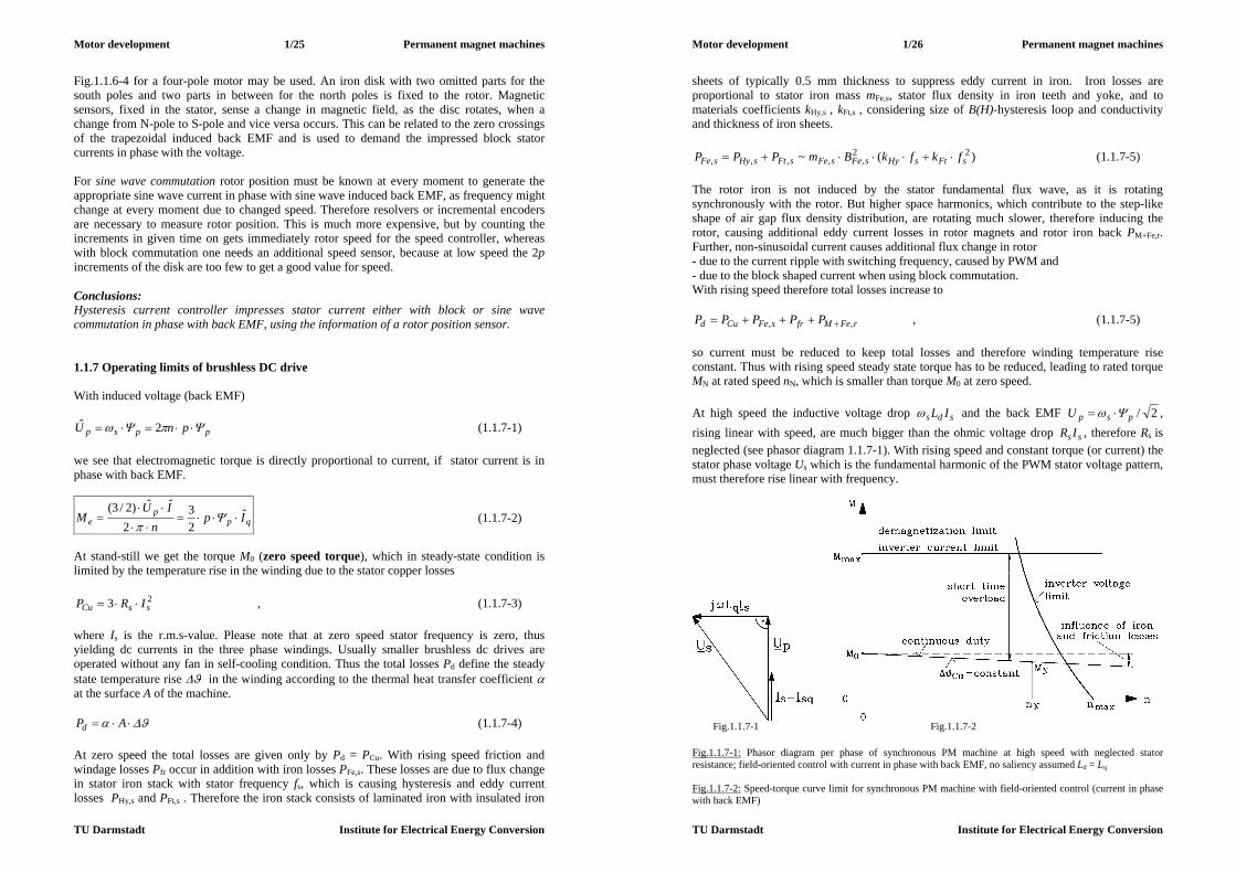
Motor development 1/25 Permanent magnet machines
TU Darmstadt Institute for Electrical Energy Conversion
Fig.1.1.6-4 for a four-pole motor may be used. An iron disk with two omitted parts for the south poles and two parts in between for the north poles is fixed to the rotor. Magnetic sensors, fixed in the stator, sense a change in magnetic field, as the disc rotates, when a change from N-pole to S-pole and vice versa occurs. This can be related to the zero crossings of the trapezoidal induced back EMF and is used to demand the impressed block stator currents in phase with the voltage. For sine wave commutation rotor position must be known at every moment to generate the appropriate sine wave current in phase with sine wave induced back EMF, as frequency might change at every moment due to changed speed. Therefore resolvers or incremental encoders are necessary to measure rotor position. This is much more expensive, but by counting the increments in given time on gets immediately rotor speed for the speed controller, whereas with block commutation one needs an additional speed sensor, because at low speed the 2p increments of the disk are too few to get a good value for speed. Conclusions: Hysteresis current controller impresses stator current either with block or sine wave commutation in phase with back EMF, using the information of a rotor position sensor. 1.1.7 Operating limits of brushless DC drive With induced voltage (back EMF)
ppsp pnU 2ˆ (1.1.7-1) we see that electromagnetic torque is directly proportional to current, if stator current is in phase with back EMF.
qpp
e Ipn
IUM ˆ
23
2
ˆˆ)2/3(
(1.1.7-2)
At stand-still we get the torque M0 (zero speed torque), which in steady-state condition is limited by the temperature rise in the winding due to the stator copper losses
23 ssCu IRP , (1.1.7-3) where Is is the r.m.s-value. Please note that at zero speed stator frequency is zero, thus yielding dc currents in the three phase windings. Usually smaller brushless dc drives are operated without any fan in self-cooling condition. Thus the total losses Pd define the steady state temperature rise in the winding according to the thermal heat transfer coefficient at the surface A of the machine.
APd (1.1.7-4) At zero speed the total losses are given only by Pd = PCu. With rising speed friction and windage losses Pfr occur in addition with iron losses PFe,s. These losses are due to flux change in stator iron stack with stator frequency fs, which is causing hysteresis and eddy current losses PHy,s and PFt,s . Therefore the iron stack consists of laminated iron with insulated iron
Motor development 1/26 Permanent magnet machines
TU Darmstadt Institute for Electrical Energy Conversion
sheets of typically 0.5 mm thickness to suppress eddy current in iron. Iron losses are proportional to stator iron mass mFe,s, stator flux density in iron teeth and yoke, and to materials coefficients kHy,s , kFt,s , considering size of B(H)-hysteresis loop and conductivity and thickness of iron sheets.
)(~ 22,,,,, sFtsHysFesFesFtsHysFe fkfkBmPPP (1.1.7-5)
The rotor iron is not induced by the stator fundamental flux wave, as it is rotating synchronously with the rotor. But higher space harmonics, which contribute to the step-like shape of air gap flux density distribution, are rotating much slower, therefore inducing the rotor, causing additional eddy current losses in rotor magnets and rotor iron back PM+Fe,r. Further, non-sinusoidal current causes additional flux change in rotor - due to the current ripple with switching frequency, caused by PWM and - due to the block shaped current when using block commutation. With rising speed therefore total losses increase to
rFeMfrsFeCud PPPPP ,, , (1.1.7-5) so current must be reduced to keep total losses and therefore winding temperature rise constant. Thus with rising speed steady state torque has to be reduced, leading to rated torque MN at rated speed nN, which is smaller than torque M0 at zero speed. At high speed the inductive voltage drop sds IL and the back EMF 2/pspU , rising linear with speed, are much bigger than the ohmic voltage drop ss IR , therefore Rs is neglected (see phasor diagram 1.1.7-1). With rising speed and constant torque (or current) the stator phase voltage Us which is the fundamental harmonic of the PWM stator voltage pattern, must therefore rise linear with frequency.
Fig.1.1.7-1 Fig.1.1.7-2 Fig.1.1.7-1: Phasor diagram per phase of synchronous PM machine at high speed with neglected stator resistance; field-oriented control with current in phase with back EMF, no saliency assumed Ld = Lq Fig.1.1.7-2: Speed-torque curve limit for synchronous PM machine with field-oriented control (current in phase with back EMF)
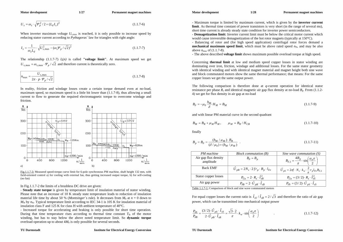
Motor development 1/27 Permanent magnet machines
TU Darmstadt Institute for Electrical Energy Conversion
22 )(2/ sdpss ILU (1.1.7-6) When inverter maximum voltage Us,max is reached, it is only possible to increase speed by reducing stator current according to Pythagoras´ law for triangles with right angle:
22max, )2/(1
pssds
s UL
I
(1.1.7-7)
The relationship (1.1.7-7) Is(n) is called "voltage limit". At maximum speed we get
2/max,max, pssU and therefore current is theoretically zero.
2/2max,
maxp
s
pU
n
(1.1.7-8)
In reality, friction and windage losses create a certain torque demand even at no-load, maximum speed, so maximum speed is a little bit lower than (1.1.7-8), thus allowing a small current to flow to generate the required electromagnetic torque to overcome windage and friction.
a) b) Fig.1.1.7-3: Measured speed-torque curve limit for 6-pole synchronous PM machine, shaft height 132 mm, with field-oriented control a) for cooling with external fan, thus getting increased output torque, b) for self-cooling (no fan) In Fig.1.1.7-2 the limits of a brushless DC drive are given: - Steady state torque is given by temperature limit of insulation material of stator winding. Please note that an increase of 10 K steady state temperature leads to reduction of insulation material life time by about 50 % (Montsinger´s rule). It decreases from M0 at n = 0 down to MN by nN. Typical temperature limit according to IEC 34-1 is 105 K for insulation material of insulation class F and 125 K for class H with ambient temperature of 40°C. - Increased torque for accelerating and braking is only possible for short time operation. During that time temperature rises according to thermal time constant Tth of the motor winding, but has to stay below the above noted temperature limit. So dynamic torque overload operation up to about 4M0 is only possible for several seconds.
Motor development 1/28 Permanent magnet machines
TU Darmstadt Institute for Electrical Energy Conversion
- Maximum torque is limited by maximum current, which is given by the inverter current limit. As thermal time constant of power transistors is very short (in the range of several ms), short time current is already steady state condition for inverter power semiconductors. - Demagetization limit: Inverter current limit must be below the critical motor current which would cause irreversible demagnetization of the hot rotor magnets (typically at 150°C). - Balancing of rotor and (for high speed application) centrifugal rotor forces demand a mechanical maximum speed limit, which must be above rated speed nN, and may be also above nmax of (1.1.7-8). - The above described voltage limit shows maximum possible overload torque at high speed. Concerning thermal limit at low and medium speed copper losses in stator winding are dominating over iron, friction, windage and additional losses. For the same stator geometry with identical winding and with identical magnet material and magnet height both sine wave and block commutated motors show the same thermal performance; that means: For the same copper losses we get the same output power. The following comparison is therefore done at q-current operation for identical stator resistance per phase Rs and identical magnetic air gap flux density at no-load Bp. From (1.1.2-4) we get for flux density in air gap at no-load
MMM BHhB
0 (1.1.7-9)
and with linear PM material curve in the second quadrant
CBRMMMRM HBHBB /, (1.1.7-10) finally
)/()/()/(
0 MM
RMMp h
BhBB
. (1.1.7-11)
PM machine Block commutation (B) Sine wave commutation (S)
Air gap flux density amplitude
pBB
2sin
41,
epBB
Back EMF FeppspB lBfNU 22ˆ
1,22ˆ
BlkNfU FepwspS
Stator copper losses 2ˆ2 sBsCu IRP 2ˆ)2/3( sSsCu IRP Air gap power
sBpBB IUP ˆˆ2 sSpSS IUP ˆˆ)2/3( Table 1.1.7-1: Comparison of block and sine wave commutated motors For equal copper losses the current ratio is 3/2ˆ/ˆ sBsS II and therefore the ratio of air gap power, which can be transmitted into mechanical output power
2sin23
ˆˆ2
ˆˆ)2/3(
ew
sBpB
sSpS
B
S kIU
IUPP . (1.1.7-12)
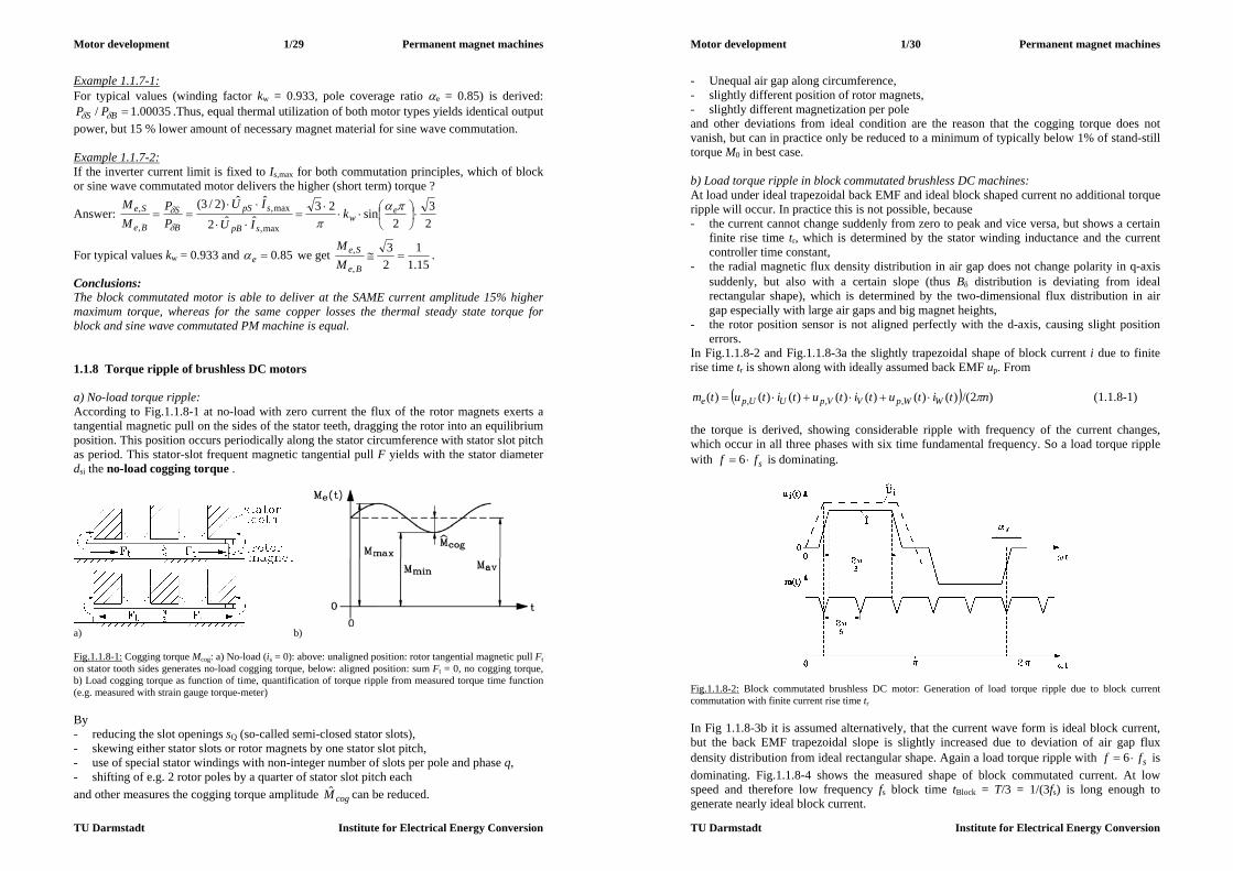
Motor development 1/29 Permanent magnet machines
TU Darmstadt Institute for Electrical Energy Conversion
Example 1.1.7-1: For typical values (winding factor kw = 0.933, pole coverage ratio e = 0.85) is derived:
00035.1/ BS PP .Thus, equal thermal utilization of both motor types yields identical output power, but 15 % lower amount of necessary magnet material for sine wave commutation. Example 1.1.7-2: If the inverter current limit is fixed to Is,max for both commutation principles, which of block or sine wave commutated motor delivers the higher (short term) torque ?
Answer: 23
2sin23
ˆˆ2
ˆˆ)2/3(
max,
max,
,
,
ew
spB
spS
B
S
Be
Se kIU
IUPP
MM
For typical values kw = 0.933 and 85.0e we get 15.11
23
,
, Be
Se
MM
.
Conclusions: The block commutated motor is able to deliver at the SAME current amplitude 15% higher maximum torque, whereas for the same copper losses the thermal steady state torque for block and sine wave commutated PM machine is equal. 1.1.8 Torque ripple of brushless DC motors a) No-load torque ripple: According to Fig.1.1.8-1 at no-load with zero current the flux of the rotor magnets exerts a tangential magnetic pull on the sides of the stator teeth, dragging the rotor into an equilibrium position. This position occurs periodically along the stator circumference with stator slot pitch as period. This stator-slot frequent magnetic tangential pull F yields with the stator diameter dsi the no-load cogging torque .
a) b) Fig.1.1.8-1: Cogging torque Mcog: a) No-load (is = 0): above: unaligned position: rotor tangential magnetic pull Ft on stator tooth sides generates no-load cogging torque, below: aligned position: sum Ft = 0, no cogging torque, b) Load cogging torque as function of time, quantification of torque ripple from measured torque time function (e.g. measured with strain gauge torque-meter) By - reducing the slot openings sQ (so-called semi-closed stator slots), - skewing either stator slots or rotor magnets by one stator slot pitch, - use of special stator windings with non-integer number of slots per pole and phase q, - shifting of e.g. 2 rotor poles by a quarter of stator slot pitch each and other measures the cogging torque amplitude cogM can be reduced.
Motor development 1/30 Permanent magnet machines
TU Darmstadt Institute for Electrical Energy Conversion
- Unequal air gap along circumference, - slightly different position of rotor magnets, - slightly different magnetization per pole and other deviations from ideal condition are the reason that the cogging torque does not vanish, but can in practice only be reduced to a minimum of typically below 1% of stand-still torque M0 in best case. b) Load torque ripple in block commutated brushless DC machines: At load under ideal trapezoidal back EMF and ideal block shaped current no additional torque ripple will occur. In practice this is not possible, because - the current cannot change suddenly from zero to peak and vice versa, but shows a certain
finite rise time tr, which is determined by the stator winding inductance and the current controller time constant,
- the radial magnetic flux density distribution in air gap does not change polarity in q-axis suddenly, but also with a certain slope (thus B distribution is deviating from ideal rectangular shape), which is determined by the two-dimensional flux distribution in air gap especially with large air gaps and big magnet heights,
- the rotor position sensor is not aligned perfectly with the d-axis, causing slight position errors.
In Fig.1.1.8-2 and Fig.1.1.8-3a the slightly trapezoidal shape of block current i due to finite rise time tr is shown along with ideally assumed back EMF up. From
)2/()()()()()()()( ,,, ntitutitutitutm WWpVVpUUpe (1.1.8-1) the torque is derived, showing considerable ripple with frequency of the current changes, which occur in all three phases with six time fundamental frequency. So a load torque ripple with sff 6 is dominating.
Fig.1.1.8-2: Block commutated brushless DC motor: Generation of load torque ripple due to block current commutation with finite current rise time tr In Fig 1.1.8-3b it is assumed alternatively, that the current wave form is ideal block current, but the back EMF trapezoidal slope is slightly increased due to deviation of air gap flux density distribution from ideal rectangular shape. Again a load torque ripple with sff 6 is dominating. Fig.1.1.8-4 shows the measured shape of block commutated current. At low speed and therefore low frequency fs block time tBlock = T/3 = 1/(3fs) is long enough to generate nearly ideal block current.
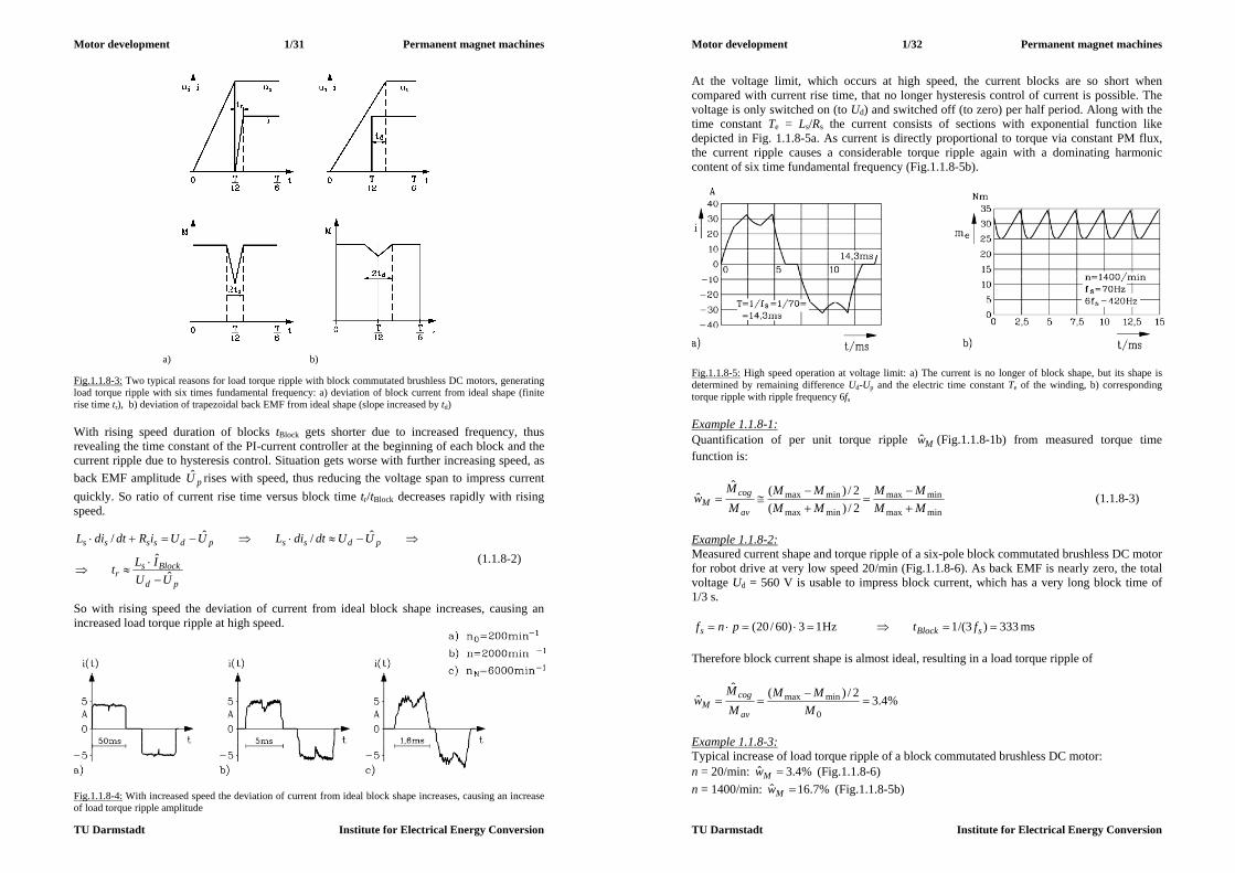
Motor development 1/31 Permanent magnet machines
TU Darmstadt Institute for Electrical Energy Conversion
a) b) Fig.1.1.8-3: Two typical reasons for load torque ripple with block commutated brushless DC motors, generating load torque ripple with six times fundamental frequency: a) deviation of block current from ideal shape (finite rise time tr), b) deviation of trapezoidal back EMF from ideal shape (slope increased by td) With rising speed duration of blocks tBlock gets shorter due to increased frequency, thus revealing the time constant of the PI-current controller at the beginning of each block and the current ripple due to hysteresis control. Situation gets worse with further increasing speed, as back EMF amplitude pU rises with speed, thus reducing the voltage span to impress current quickly. So ratio of current rise time versus block time tr/tBlock decreases rapidly with rising speed.
pd
Blocksr
pdsspdssss
UUILt
UUdtdiLUUiRdtdiL
ˆˆ
ˆ/ˆ/
(1.1.8-2)
So with rising speed the deviation of current from ideal block shape increases, causing an increased load torque ripple at high speed.
Fig.1.1.8-4: With increased speed the deviation of current from ideal block shape increases, causing an increase of load torque ripple amplitude
Motor development 1/32 Permanent magnet machines
TU Darmstadt Institute for Electrical Energy Conversion
At the voltage limit, which occurs at high speed, the current blocks are so short when compared with current rise time, that no longer hysteresis control of current is possible. The voltage is only switched on (to Ud) and switched off (to zero) per half period. Along with the time constant Te = Ls/Rs the current consists of sections with exponential function like depicted in Fig. 1.1.8-5a. As current is directly proportional to torque via constant PM flux, the current ripple causes a considerable torque ripple again with a dominating harmonic content of six time fundamental frequency (Fig.1.1.8-5b).
Fig.1.1.8-5: High speed operation at voltage limit: a) The current is no longer of block shape, but its shape is determined by remaining difference Ud-Up and the electric time constant Te of the winding, b) corresponding torque ripple with ripple frequency 6fs Example 1.1.8-1: Quantification of per unit torque ripple Mw (Fig.1.1.8-1b) from measured torque time function is:
minmax
minmax
minmax
minmax2/)(2/)(ˆ
ˆMMMM
MMMM
MM
wav
cogM
(1.1.8-3)
Example 1.1.8-2: Measured current shape and torque ripple of a six-pole block commutated brushless DC motor for robot drive at very low speed 20/min (Fig.1.1.8-6). As back EMF is nearly zero, the total voltage Ud = 560 V is usable to impress block current, which has a very long block time of 1/3 s.
13)60/20( pnfs Hz 333)3/(1 sBlock ft ms Therefore block current shape is almost ideal, resulting in a load torque ripple of
%4.32/)(ˆˆ
0
minmax
M
MMMM
wav
cogM
Example 1.1.8-3: Typical increase of load torque ripple of a block commutated brushless DC motor: n = 20/min: %4.3ˆ Mw (Fig.1.1.8-6) n = 1400/min: %7.16ˆ Mw (Fig.1.1.8-5b)

Motor development 1/33 Permanent magnet machines
TU Darmstadt Institute for Electrical Energy Conversion
Fig.1.1.8-6: Measured block current and corresponding torque ripple (measured with strain gauge torque-meter) at very low speed 20/min c) Load torque ripple in sine wave commutated brushless DC machines: As current changes sinusoidal, the sudden current changes of block commutated machines, which are difficult to realize especially at increased speed, do not occur. Further, the air gap flux density distribution does not need to be of ideal rectangular shape, as only the fundamental of the air gap flux is used for force generation. Due to the sinusoidal wave form of both back EMF and current, a position error of the position sensor results only in a reduction of torque due to a phase shift between sinus current and sinus back EMF, but not in an increased torque ripple. So, the load torque ripple of sine wave commutated machines is much smaller than of block commutated machines. Good sine wave commutated brushless DC drives show a total current ripple (no-load and load) of %1ˆ Mw . Example 1.1.8-4: Comparison of Fourier analysis of torque ripple at rated torque and very low speed 20/min for a) block commutated 6-pole motor and b) sine wave commutated 8-pole motor (Fig.1.1.8-7). The harmonic content of a) shows a dominating 6th harmonic in torque ripple, which in b) is very small. Thus with a) in best case a load torque ripple at very low speed of about
%4...3ˆ Mw can be achieved, whereas with b) lower values %1ˆ Mw are possible.
Fig.1.1.8-7: Measured Fourier spectrum of torque ripple of a) block commutated and b) sine wave commutated brushless DC machine (ripple measured with strain gauge torque-meter at very low speed 20/min)
Motor development 1/34 Permanent magnet machines
TU Darmstadt Institute for Electrical Energy Conversion
Conclusions: The sine wave commutated motor has a lower load dependent torque ripple than the block commutated brushless DC drive. 1.1.9 Significance of torque ripple for motor and drive performance a) Torsion resonance: A drive system consists typically of the motor (rotor inertia JM) and driven load (rotary inertia JL) with usually an elastic coupling (torsion spring coefficient c) in between (Fig.1.1.9-1).
a) b) Fig.1.1.9-1: Torsion resonance: a) Rotor of motor coupled to rotating load via an elastic coupling, b) Shaft torque amplitude, excited by air gap cogging torque Let us assume that a cogging torque with e.g. dominant frequency k = 6 (block commutated brushless DC drive)
)2(),sin(ˆ)(, pnktMtm ce (1.1.9-1) acting in addition to the motor torque, which causes the speed n. For evaluating the oscillating shaft torque ms at the coupling the torque equation for both rotor bodies with their oscillation angles M, L yields
LMscesMMsLL cmmmJmJ ,,0 , (1.1.9-2) or with
M
ces
LMLMMsceMLsL J
mm
JJJmmJm ,
,11/)(,/
(1.1.9-3)
finally the system differential equation (with abbreviation LM )
M
ce
LM
LMJm
JJJJc ,)(
. (1.1.9-4)
Solution for exciting torque ripple (1.1.9-1) yields for the torsion vibration angle and for the oscillating shaft torque ms :
)sin(1ˆ)( 22 t
JMt
oM
, )sin(
ˆ)()( 22 tc
JMtctm
oMs
(1.1.9-5)

Motor development 1/35 Permanent magnet machines
TU Darmstadt Institute for Electrical Energy Conversion
If the frequency of the cogging torque f = /(2) equals the torsion resonance frequency of the drive system
LM
LMJJJJcf
21)2/(00 , (1.1.9-6)
the shaft torque – in spite of the small cogging torque amplitude M - gets infinite, as no damping is assumed. In that case the coupling will break (“torsion resonance”). Conclusions: It must be avoided that the dominant cogging torque frequency excites the torsion resonance of the drive system. This can be achieved by designing the drive with a stiff coupling (c: high value) to stay with cogging torque frequency below the resonance. At low speed n the cogging torque frequency f = /(2) = k.n.p is also low: 0 . Therefore the oscillating shaft torque at low speed is
)sin(ˆ
)sin(ˆ
)( 20
tJJJMtc
JMtm
ML
L
Ms
(1.1.9-7)
directly proportional to the cogging torque in the motor air gap. In measurement systems for cogging torque therefore a load machine is coupled to the test motor with additional inertia disc to get JL >> JM in order to get ms(t) me,c(t). Thus a torquemeter in the coupling – measuring shaft oscillating torque – also directly measures the cogging torque (e.g. like in section 1.1.8). b) Speed ripple: Due to cogging torque an additional speed ripple n is superimposed to constant speed
)()( tnntn , (1.1.9-8) bringing difficulty for smooth positioning in tooling machinery such as grinding, milling, polishing etc., as the surface of the working piece gets a slight ripple, which is clearly visible with the eye, when observing the reflected light from the surface.
)2/()()( ttn M (1.1.9-9)
)sin(/1ˆ)()()( 22 tJc
JM
Jtmtmt
o
M
MM
seM
(1.1.9-10)
)cos(/12
ˆ)2/()()( 22 tJc
JMttn
o
M
MM
(1.1.9-11)
Staying below the resonance 0 , we observe that especially at low speed the speed ripple amplitude, expressed as percentage of actual speed, increases with DECREASING speed:
Motor development 1/36 Permanent magnet machines
TU Darmstadt Institute for Electrical Energy Conversion
2222222
1~)()2(
ˆ/1)2(
ˆ
nJJnpkMJc
JnpkM
nn
MLo
M
M
(1.1.9-12)
Note, that due to operation well below resonance the result could have also been obtained by considering a very stiff coupling between motor and load ( LMc ) , getting a much simpler differential equation:
)cos()(2
ˆ)()sin(ˆ)( t
JJMtntMJJ
MLMML
(1.1.9-13)
Conclusions: Especially at low speed the torque ripple leads to considerable speed ripple, when compared with actual speed. Therefore servo drive applications with positioning tasks are sensitive to torque ripple, demanding low cogging torque amplitudes. 1.2 Brushless DC drive systems Brushless DC drive systems are positioning drives of utmost accuracy with very smooth torque at low speed as so called servo drives. A high overload capability for fast acceleration yields a high dynamic performance. A motor as electromechanical energy conversion actuator, a positioning measurement system, a power electronic system for motor feeding and a control system for motion control comprise the basic elements for a high performance brushless DC servo drive system. The whole drive is usually connected to an electronic bus system such as - PROFIBUS (Process Field Bus), - Drivecom-Bus (Interbus-S), - SERCOS-Interface, - CAN-Bus (Controller Area Network), - ASI (Actor-Sensor-Interface) or others. 1.2.1 Block commutated drives According to Fig. 1.2.1-1 a block commutated drive system consists of - a permanent magnet motor with three phase, single layer winding, skewed slots and 100%
pole coverage ratio for the rotor magnets, - a simple rotor position sensor with rotor disc according to pole number, - a brushless DC tachometer for speed measurement, - an encoder with high resolution for precise positioning, - a voltage source inverter system with power transistors and speed and current control,
implemented in a micro-computer system and motor current measurement devices such as shunts or DC transformers with Hall-sensors,
- a motion control system, which is implemented in a second microcomputer and allows position control, but also different motion control such as special velocity profiles according to the needs of the driven load.
Often the motion control due to the modern powerful microcomputer systems is nowadays implemented in the inverter itself.
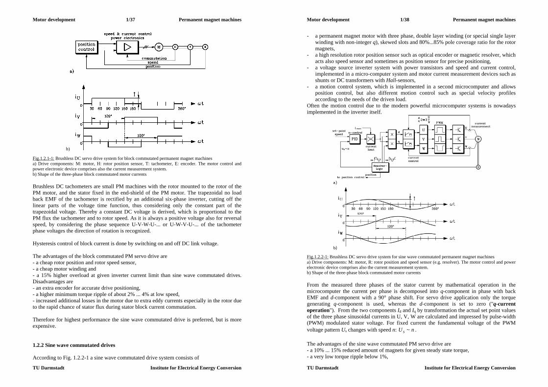
Motor development 1/37 Permanent magnet machines
TU Darmstadt Institute for Electrical Energy Conversion
b)
Fig.1.2.1-1: Brushless DC servo drive system for block commutated permanent magnet machines a) Drive components: M: motor, H: rotor position sensor, T: tachometer, E: encoder. The motor control and power electronic device comprises also the current measurement system. b) Shape of the three-phase block commutated motor currents
Brushless DC tachometers are small PM machines with the rotor mounted to the rotor of the PM motor, and the stator fixed in the end-shield of the PM motor. The trapezoidal no load back EMF of the tachometer is rectified by an additional six-phase inverter, cutting off the linear parts of the voltage time function, thus considering only the constant part of the trapezoidal voltage. Thereby a constant DC voltage is derived, which is proportional to the PM flux the tachometer and to rotor speed. As it is always a positive voltage also for reversal speed, by considering the phase sequence U-V-W-U-... or U-W-V-U-... of the tachometer phase voltages the direction of rotation is recognized. Hysteresis control of block current is done by switching on and off DC link voltage. The advantages of the block commutated PM servo drive are - a cheap rotor position and rotor speed sensor, - a cheap motor winding and - a 15% higher overload at given inverter current limit than sine wave commutated drives. Disadvantages are - an extra encoder for accurate drive positioning, - a higher minimum torque ripple of about 2% ... 4% at low speed, - increased additional losses in the motor due to extra eddy currents especially in the rotor due to the rapid chance of stator flux during stator block current commutation. Therefore for highest performance the sine wave commutated drive is preferred, but is more expensive. 1.2.2 Sine wave commutated drives According to Fig. 1.2.2-1 a sine wave commutated drive system consists of
Motor development 1/38 Permanent magnet machines
TU Darmstadt Institute for Electrical Energy Conversion
- a permanent magnet motor with three phase, double layer winding (or special single layer winding with non-integer q), skewed slots and 80%...85% pole coverage ratio for the rotor magnets,
- a high resolution rotor position sensor such as optical encoder or magnetic resolver, which acts also speed sensor and sometimes as position sensor for precise positioning,
- a voltage source inverter system with power transistors and speed and current control, implemented in a micro-computer system and motor current measurement devices such as shunts or DC transformers with Hall-sensors,
- a motion control system, which is implemented in a second microcomputer and allows position control, but also different motion control such as special velocity profiles according to the needs of the driven load.
Often the motion control due to the modern powerful microcomputer systems is nowadays implemented in the inverter itself.
Fig.1.2.2-1: Brushless DC servo drive system for sine wave commutated permanent magnet machines a) Drive components: M: motor, R: rotor position and speed sensor (e.g. resolver). The motor control and power electronic device comprises also the current measurement system. b) Shape of the three-phase block commutated motor currents
From the measured three phases of the stator current by mathematical operation in the microcomputer the current per phase is decomposed into q-component in phase with back EMF and d-component with a 90° phase shift. For servo drive application only the torque generating q-component is used, whereas the d-component is set to zero ("q-current operation"). From the two components Id and Iq by transformation the actual set point values of the three phase sinusoidal currents in U, V, W are calculated and impressed by pulse-width (PWM) modulated stator voltage. For fixed current the fundamental voltage of the PWM voltage pattern Us changes with speed n: nU s ~ . The advantages of the sine wave commutated PM servo drive are - a 10% ... 15% reduced amount of magnets for given steady state torque, - a very low torque ripple below 1%,
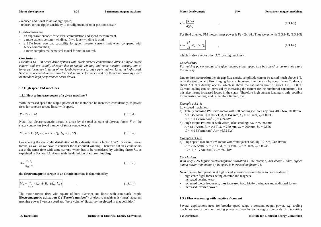
Motor development 1/39 Permanent magnet machines
TU Darmstadt Institute for Electrical Energy Conversion
- reduced additional losses at high speed, - reduced torque ripple sensitivity to misalignment of rotor position sensor. Disadvantages are - an expensive encoder for current commutation and speed measurement, - a more expensive stator winding, if two layer winding is used, - a 15% lower overload capability for given inverter current limit when compared with
block commutation, - a more complex mathematical model for motor control. Conclusions: Brushless DC PM servo drive systems with block current commutation offer a simple motor control and are usually cheaper due to simple winding and rotor position sensing, but at lower performance in terms of low load-dependent torque ripple and low losses at high speed. Sine wave operated drives show the best servo performance and are therefore nowadays used as standard high performance servo drives. 1.3 High speed PM machines 1.3.1 How to increase power of a given machine ? With increased speed the output power of the motor can be increased considerably, as power rises for constant torque linear with speed.
MnP 2 (1.3.1-1) Note, that electromagnetic torque is given by the total amount of Lorentz-forces F on the stator conductors (total number of stator conductors: z)
)2/()2/( siFessie dlBIzdFzM . (1.3.1-2) Considering the sinusoidal distribution of flux density gives a factor 2/1 for overall mean torque, as well as we have to consider the distributed winding. Therefore not all z conductors act at the same time with same current, which has to be considered by winding factor kw, as explained in Section 1.1. Along with the definition of current loading
si
sd
IzA (1.3.1-3)
the electromagnetic torque of an electric machine is determined by
)(22
2Fesiwe ldBAkM
. (1.3.1-4)
The motor torque rises with square of bore diameter and linear with iron stack length. Electromagnetic utilization C (“Esson´s number”) of electric machines is (inner) apparent machine power S versus speed and “bore volume” (factor /4 neglected in that definition)
Motor development 1/40 Permanent magnet machines
TU Darmstadt Institute for Electrical Energy Conversion
FesildnSC 2
)/( . (1.3.1-5)
For field oriented PM motors inner power is P = 2nMe. Thus we get with (1.3.1-4), (1.3.1-5)
BAkC w
2
2 , (1.3.1-6)
which is also true for other AC rotating machines. Conclusions: For raising power output of a given motor, either speed can be raised or current load and flux density. Due to iron saturation the air gap flux density amplitude cannot be raised much above 1 T, as in the teeth, where flux fringing leads to increased flux density by about factor 2, already about 2 T flux density occurs, which is above the saturation limit of about 1.7 ... 1.8 T. Current loading can be increased by increasing the current (or the number of conductors), but this also means increased losses in the stator. Therefore high current loading is only possible for intensive cooling, and is therefore limited, too. Example 1.3.1-1: Low speed machines: a) Totally enclosed PM servo motor with self cooling (without any fan): 40.5 Nm, 1000/min
A = 145 A/cm, B = 0.65 T, dsi = 154 mm, lFe = 175 mm, kw = 0.933 C = 1.0 kVAmin/m3, P = 4.24 kW
b) High torque PM motor with water jacket cooling: 737 Nm, 600/min A = 611 A/cm, B = 0.8 T, dsi = 280 mm, lFe = 200 mm, kw = 0.866 C = 4.9 kVAmin/m3, P = 46.32 kW
Example 1.3.1-2: c) High speed machine: PM motor with water jacket cooling: 12 Nm, 24000/min
A = 225 A/cm, B = 0.7 T, dsi = 90 mm, lFe = 90 mm, kw = 0.933 C = 1.7 kVAmin/m3, P = 30.0 kW
Conclusions: With only 70% higher electromagnetic utilization C the motor c) has about 7 times higher output power than motor a), as speed is increased by factor 24. Nevertheless, for operation at high speed several constraints have to be considered: - high centrifugal forces acting on rotor and magnets - increased bearing wear - increased motor frequency, thus increased iron, friction, windage and additional losses - increased inverter power. 1.3.2 Flux weakening with negative d-current Several applications need for broader speed range a constant output power, e.g. tooling machines need a constant cutting power – given by technological demands of the cutting

Motor development 1/41 Permanent magnet machines
TU Darmstadt Institute for Electrical Energy Conversion
process - in order to get good results. Nevertheless this cutting power is needed at high speed to get a quick cutting process (“HSC – high speed cutting”). In Fig.1.3.2-1 the power demand is shown. Above rated speed nN the power is kept constant. The torque therefore decreases with 1/n, thus the motor is oversized at high speed, but not at low speed, where full torque is required. In order not to oversize the expensive inverter, the inverter power reaches its maximum voltage at rated speed. Below rated speed, for maximum torque the current limit of the inverter is used, as torque in field-oriented controlled PM machines is proportional to current.
0,~ dqssp IIIIM (1.3.2-1) At speed above rated speed the back EMF rises further, as it is directly proportional to speed:
nU pp ~ (1.3.2-2)
Fig.1.3.2-1: Variable speed, constant power operation, showing maximum required torque, stator voltage and back EMF In order to avoid “voltage limit” due to Iq-operation and to reach much higher speed, a negative d-current component Id is added, as is shown in the phasor diagrams of Fig.1.3.2-2. Example 1.3.2-1: Operation of PM synchronous motor with flux weakening (Fig.1.3.2-2): Voltage limit of inverter Us,max = UN (=100%), inverter current limit Is,max = 2IN (= 200% of rated value). Synchronous reactance xd = Xd/ZN = 0.33 p.u.; ZN = UN/IN, Up/UN = 0.7 at rated speed.
Voltage us
Current is d-axis isd q-axis isq Power Speed n cos
a) 0.8 1.0 0 1.0 PN nN 0.89 ind b) 1.0 2.0 0 2.0 2PN nN 0.7 ind c) 1.0 1.5 -0.8 1.2 2PN 1.67nN 0.98 ind d) 1.0 1.7 -1.6 0.5 2PN 4nN 0.89 cap
Table 1.3.2-1: Electric data of variable speed PM motor with flux weakening (p.u.-values: us = Us/UN, is = Is/IN) At rated speed, rated torque (Fig.1.3.2-2a) the field oriented control as described in Section 1.1 is used with only q-current operation. For overload torque at rated speed the stator voltage has to be increased to Us,max as well as the current to inverter its current limit Is,max, still as a q-current (Fig.1.3.2-2b). For further speed increase the rising back EMF has to be reduced by an additional voltage drop at stator reactance sdss LX (Fig.1.3.2-2c). According to
Motor development 1/42 Permanent magnet machines
TU Darmstadt Institute for Electrical Energy Conversion
22dqs III (1.3.2-3)
an additional (negative) d-current component means a necessary reduction of Iq. This is possible, as the torque demand in the constant power range decreases. As long as the decrease of q-current balances the increased demand of negative d-current component, the inverter is able to supply the needed current. In Fig.1.3.2-2d at n = 4nN, the back EMF is 4 times higher than at rated speed, but the required torque only Mmax/4. Therefore only Iq = Is,max/4 ( = 0.5IN) is needed, leaving 96.8% of inverter current limit for flux weakening component Id.
Us
dp
Is Isq=
Up
X Iss
3b
q
q
Us
d
Up
3a
Is Isq=
X Iss
p
Isd
Us
X Iss
p d
3c
Is Isq
Up
q
3d
Up
q
Us
X Iss
d
Is
IsdIsq p
Fig.1.3.2-2: Phasor diagrams of PM machine with field weakening (stator resistance Rs neglected): a) rated speed, rated torque, b) rated speed, overload torque, c) speed at 170% rated speed, decreased torque, flux weakening by negative Id-current, d) very high speed (400%) can only be reached by strong field weakening; nearly the whole current consists of
flux weakening component Id, whereas torque-producing component Iq is very small.
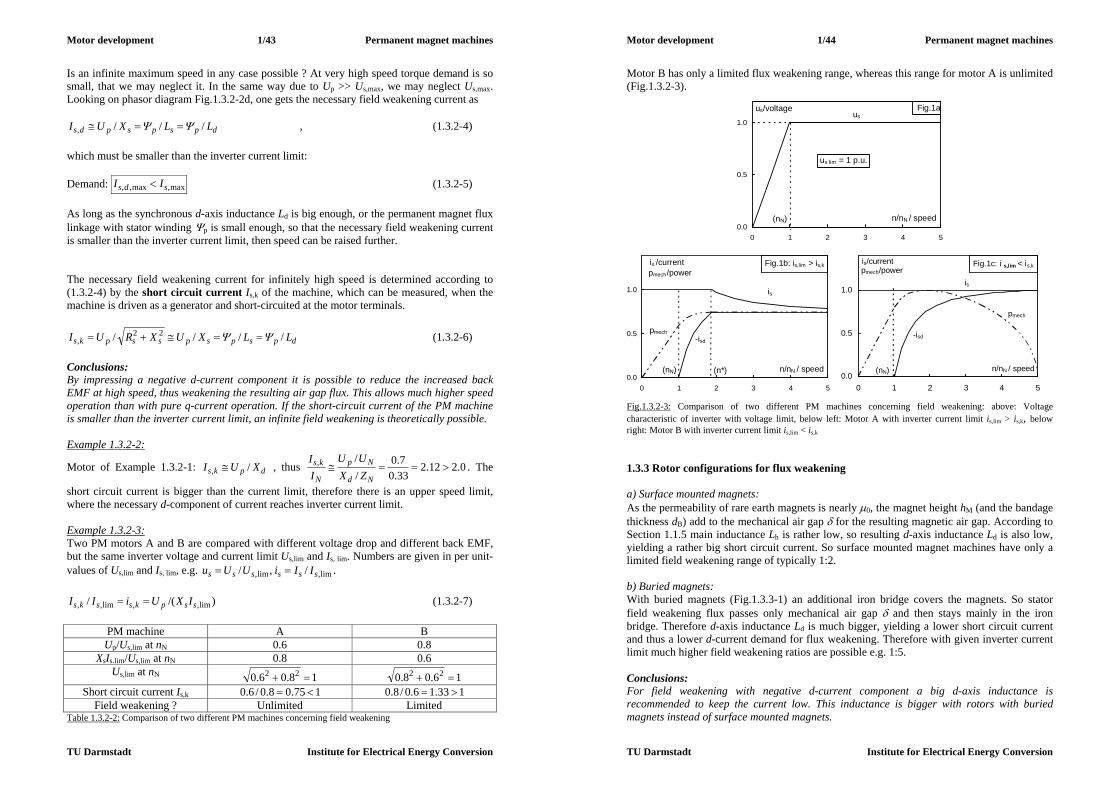
Motor development 1/43 Permanent magnet machines
TU Darmstadt Institute for Electrical Energy Conversion
Is an infinite maximum speed in any case possible ? At very high speed torque demand is so small, that we may neglect it. In the same way due to Up >> Us,max, we may neglect Us,max. Looking on phasor diagram Fig.1.3.2-2d, one gets the necessary field weakening current as
dpspspds LLXUI ///, , (1.3.2-4) which must be smaller than the inverter current limit: Demand: max,max,, sds II (1.3.2-5) As long as the synchronous d-axis inductance Ld is big enough, or the permanent magnet flux linkage with stator winding p is small enough, so that the necessary field weakening current is smaller than the inverter current limit, then speed can be raised further. The necessary field weakening current for infinitely high speed is determined according to (1.3.2-4) by the short circuit current Is,k of the machine, which can be measured, when the machine is driven as a generator and short-circuited at the motor terminals.
dpspspsspks LLXUXRUI //// 22, (1.3.2-6)
Conclusions: By impressing a negative d-current component it is possible to reduce the increased back EMF at high speed, thus weakening the resulting air gap flux. This allows much higher speed operation than with pure q-current operation. If the short-circuit current of the PM machine is smaller than the inverter current limit, an infinite field weakening is theoretically possible. Example 1.3.2-2:
Motor of Example 1.3.2-1: dpks XUI /, , thus 0.212.233.07.0
//,
Nd
Np
N
ks
ZXUU
II
. The
short circuit current is bigger than the current limit, therefore there is an upper speed limit, where the necessary d-component of current reaches inverter current limit. Example 1.3.2-3: Two PM motors A and B are compared with different voltage drop and different back EMF, but the same inverter voltage and current limit Us,lim and Is, lim. Numbers are given in per unit-values of Us,lim and Is, lim, e.g. lim,lim, /,/ ssssss IIiUUu .
)/(/ lim,,lim,, sspkssks IXUiII (1.3.2-7)
PM machine A B Up/Us,lim at nN 0.6 0.8
XsIs.lim/Us,lim at nN 0.8 0.6 Us,lim at nN 18.06.0 22 16.08.0 22
Short circuit current Is,k 175.08.0/6.0 133.16.0/8.0 Field weakening ? Unlimited Limited
Table 1.3.2-2: Comparison of two different PM machines concerning field weakening
Motor development 1/44 Permanent magnet machines
TU Darmstadt Institute for Electrical Energy Conversion
Motor B has only a limited flux weakening range, whereas this range for motor A is unlimited (Fig.1.3.2-3).
0.0
0.5
1.0
0 1 2 3 4 5
n/nN / speed
us lim = 1 p.u.
us
(nN)
us/voltage Fig.1a
Fig.1b: is,lim > is,k
0.0
0.5
1.0
0 1 2 3 4 5
n/nN / speed
is /current
is
-isd
pmech
(nN) (n*)
pmech/power
Fig.1c: i s,lim < is,k
0.0
0.5
1.0
0 1 2 3 4 5
n/nN / speed
is/current
is
-isd
pmech
(nN)
pmech/power
Fig.1.3.2-3: Comparison of two different PM machines concerning field weakening: above: Voltage characteristic of inverter with voltage limit, below left: Motor A with inverter current limit is,lim > is,k, below right: Motor B with inverter current limit is,lim < is,k 1.3.3 Rotor configurations for flux weakening a) Surface mounted magnets: As the permeability of rare earth magnets is nearly 0, the magnet height hM (and the bandage thickness dB) add to the mechanical air gap for the resulting magnetic air gap. According to Section 1.1.5 main inductance Lh is rather low, so resulting d-axis inductance Ld is also low, yielding a rather big short circuit current. So surface mounted magnet machines have only a limited field weakening range of typically 1:2. b) Buried magnets: With buried magnets (Fig.1.3.3-1) an additional iron bridge covers the magnets. So stator field weakening flux passes only mechanical air gap and then stays mainly in the iron bridge. Therefore d-axis inductance Ld is much bigger, yielding a lower short circuit current and thus a lower d-current demand for flux weakening. Therefore with given inverter current limit much higher field weakening ratios are possible e.g. 1:5. Conclusions: For field weakening with negative d-current component a big d-axis inductance is recommended to keep the current low. This inductance is bigger with rotors with buried magnets instead of surface mounted magnets.
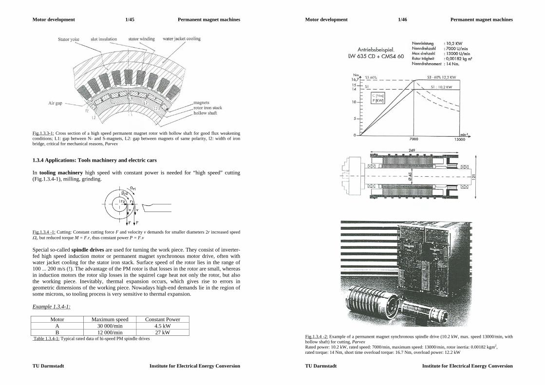
Motor development 1/45 Permanent magnet machines
TU Darmstadt Institute for Electrical Energy Conversion
Fig.1.3.3-1: Cross section of a high speed permanent magnet rotor with hollow shaft for good flux weakening conditions; L1: gap between N- and S-magnets, L2: gap between magnets of same polarity, l2: width of iron bridge, critical for mechanical reasons, Parvex 1.3.4 Applications: Tools machinery and electric cars In tooling machinery high speed with constant power is needed for “high speed” cutting (Fig.1.3.4-1), milling, grinding.
Fig.1.3.4 -1: Cutting: Constant cutting force F and velocity v demands for smaller diameters 2r increased speed r, but reduced torque M = F.r, thus constant power P = F.v Special so-called spindle drives are used for turning the work piece. They consist of inverter-fed high speed induction motor or permanent magnet synchronous motor drive, often with water jacket cooling for the stator iron stack. Surface speed of the rotor lies in the range of 100 ... 200 m/s (!). The advantage of the PM rotor is that losses in the rotor are small, whereas in induction motors the rotor slip losses in the squirrel cage heat not only the rotor, but also the working piece. Inevitably, thermal expansion occurs, which gives rise to errors in geometric dimensions of the working piece. Nowadays high-end demands lie in the region of some microns, so tooling process is very sensitive to thermal expansion. Example 1.3.4-1:
Motor Maximum speed Constant Power A 30 000/min 4.5 kW B 12 000/min 27 kW
Table 1.3.4-1: Typical rated data of hi-speed PM spindle drives
Motor development 1/46 Permanent magnet machines
TU Darmstadt Institute for Electrical Energy Conversion
Fig.1.3.4 -2: Example of a permanent magnet synchronous spindle drive (10.2 kW, max. speed 13000/min, with hollow shaft) for cutting, Parvex Rated power: 10.2 kW, rated speed: 7000/min, maximum speed: 13000/min, rotor inertia: 0.00182 kgm2, rated torque: 14 Nm, short time overload torque: 16.7 Nm, overload power: 12.2 kW

Motor development 1/47 Permanent magnet machines
TU Darmstadt Institute for Electrical Energy Conversion
With increasing maximum operating speed the rotor outer diameter dr dsi of the motor has to be reduced to keep the rotor surface speed maxmax ndv r and thus the centrifugal forces constant. Therefore with rising maximum speed the power of motors decreases.
max2
maxmaxmax
/1~)(22
22:1~ nldBAknMnPn
d Fesiwesi (1.3.4-1)
In electric or hybrid-electric cars the demanded propulsion power (e.g. 30 ... 40 kW for small sized cars) should also be delivered by very small motors, as there is not much space aboard for driving components. Most of the space is occupied by batteries. Therefore inverter-fed induction motors or PM motors must operate at high speed to get the power out of the speed, keeping the torque and thus the motor diameter small. Usually operation up 10000/min is used along with a gear, which reduces speed to the wheel rotational speed. Note that motor in electric traction must sustain 1.25nmax for 2 min. as over-speed stress during final motor test at manufacturer. Example 1.3.4-2: Medium sized car: 1400 kg mass, tire diameter D = 0.6 m, gear ratio i = 8, motor maximum speed nmax = 10000/min. How big is car maximum speed ?
3.398/)60/10000(6.0/maxmax, inDvcar m/s = 141 km/h
0
50
100
150
0 100 200 300
calculated withoutsaturationcalculated withsaturationmeasured
Is/current (A)
M/torque (Nm)
0.0
0.5
1.0
0 1 2 3 4 50.0
0.5
1.0
measuredcalculated
M/Mpk
speed
torque, power current
Pmech/Ppk
Is/Is,lim
a) b)
c) Fig.1.3.4 -3: Propulsion for electric car: a) Torque-Current-Characteristic for propulsion motor, b) Measured torque-speed drive characteristic at 132V DC, AIkWPNmM spkpk 315,35,156 lim, , (inverter) c) Prototype of fuel cell powered cars NECAR (New Electric Car) of DaimlerChrysler with electric drive system Example 1.3.4-3: (Fig.1.3.4-3) Typical electric data of motor for small sized car: outer diameter ds = 200 mm, overall length 400 mm, battery voltage 132 V = DC link voltage of inverter, inverter current limit 400 A
Motor development 1/48 Permanent magnet machines
TU Darmstadt Institute for Electrical Energy Conversion
a) constant rated torque 65 Nm between zero and rated speed nN = 2200/min b) overload torque 156 Nm for short time operation c) constant power 15 kW rated speed nN = 2200/min and max. speed nN = 10000/min d) overload power 30 kW for short time operation 1.3.5 Additional losses at high speed The following loss groups of PM synchronous motors have been already discussed in 1.1.7 and are essential for heating of stator copper winding and insulation and of rotor magnets and bandage fixing. Considering frequency pnf , we get: No-load losses: a) Iron losses: xx
Fe nBfBP 22 ~~ , (1.3.5-1) x = ca. 1.8, considering eddy-current and hysteresis losses b) Friction losses at the rotor surface (and in the bearings):
yFerfr nldP ~ (1.3.5-2)
y = 2 ... 3, depending on rotor and stator surface condition Load losses: c) Armature winding losses (copper losses):
23 ssCu IRP (1.3.5-3) d) Additional losses in rotor magnets and rotor iron:
,(, nfP rFeM current shape) znI 2~ (1.3.5-4) z = ca. 1.5 ... 2, depending on rotor geometry and stator current shape. With high speed motors the loss groups a), b) and d) dominate, and therefore special care must be taken for motor design. Low loss iron sheets with only 1 W/kg losses at 1 T, 50 Hz may reduce iron losses. Sine wave current operation is superior to block current operation yielding lower additional losses. The reason is that Fourier-analysis of block shaped current yields additional current harmonics (amplitudes Ik) with high frequencies fk >> fs , which excite additional magnetic field in air gap. These flux density waves have the same number of poles like the stator field of sine wave fundamental current Is, but they rotate with increased speed pfn kk / and therefore induce in rotor massive conductive parts like magnets or rotor iron back harmful eddy currents. Conclusions: At high speed the frequency dependent iron, friction and additional losses dominate over the copper losses. For high speed sine wave current operation should be used instead of block current, as the additional losses are much lower.
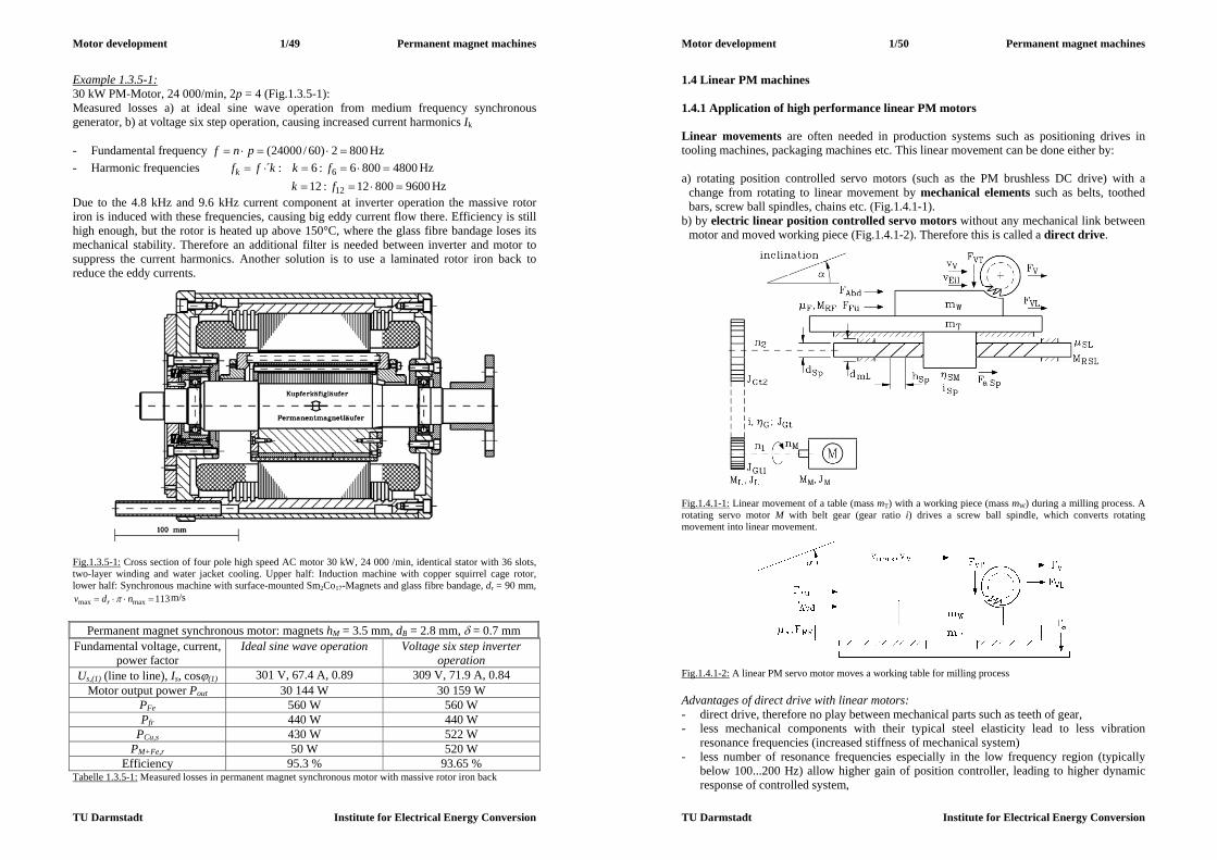
Motor development 1/49 Permanent magnet machines
TU Darmstadt Institute for Electrical Energy Conversion
Example 1.3.5-1: 30 kW PM-Motor, 24 000/min, 2p = 4 (Fig.1.3.5-1): Measured losses a) at ideal sine wave operation from medium frequency synchronous generator, b) at voltage six step operation, causing increased current harmonics Ik - Fundamental frequency 8002)60/24000( pnf Hz - Harmonic frequencies 48008006:6:´ 6 fkkffk Hz 960080012:12 12 fk Hz Due to the 4.8 kHz and 9.6 kHz current component at inverter operation the massive rotor iron is induced with these frequencies, causing big eddy current flow there. Efficiency is still high enough, but the rotor is heated up above 150°C, where the glass fibre bandage loses its mechanical stability. Therefore an additional filter is needed between inverter and motor to suppress the current harmonics. Another solution is to use a laminated rotor iron back to reduce the eddy currents.
Fig.1.3.5-1: Cross section of four pole high speed AC motor 30 kW, 24 000 /min, identical stator with 36 slots, two-layer winding and water jacket cooling. Upper half: Induction machine with copper squirrel cage rotor, lower half: Synchronous machine with surface-mounted Sm2Co17-Magnets and glass fibre bandage, dr = 90 mm,
113maxmax ndv r m/s
Permanent magnet synchronous motor: magnets hM = 3.5 mm, dB = 2.8 mm, = 0.7 mm
Fundamental voltage, current, power factor
Ideal sine wave operation Voltage six step inverter operation
Us,(1) (line to line), Is, cos(1) 301 V, 67.4 A, 0.89 309 V, 71.9 A, 0.84 Motor output power Pout 30 144 W 30 159 W
PFe 560 W 560 W Pfr 440 W 440 W
PCu,s 430 W 522 W PM+Fe,r 50 W 520 W
Efficiency 95.3 % 93.65 % Tabelle 1.3.5-1: Measured losses in permanent magnet synchronous motor with massive rotor iron back
Motor development 1/50 Permanent magnet machines
TU Darmstadt Institute for Electrical Energy Conversion
1.4 Linear PM machines 1.4.1 Application of high performance linear PM motors Linear movements are often needed in production systems such as positioning drives in tooling machines, packaging machines etc. This linear movement can be done either by: a) rotating position controlled servo motors (such as the PM brushless DC drive) with a
change from rotating to linear movement by mechanical elements such as belts, toothed bars, screw ball spindles, chains etc. (Fig.1.4.1-1).
b) by electric linear position controlled servo motors without any mechanical link between motor and moved working piece (Fig.1.4.1-2). Therefore this is called a direct drive.
Fig.1.4.1-1: Linear movement of a table (mass mT) with a working piece (mass mW) during a milling process. A rotating servo motor M with belt gear (gear ratio i) drives a screw ball spindle, which converts rotating movement into linear movement.
Fig.1.4.1-2: A linear PM servo motor moves a working table for milling process Advantages of direct drive with linear motors: - direct drive, therefore no play between mechanical parts such as teeth of gear, - less mechanical components with their typical steel elasticity lead to less vibration
resonance frequencies (increased stiffness of mechanical system) - less number of resonance frequencies especially in the low frequency region (typically
below 100...200 Hz) allow higher gain of position controller, leading to higher dynamic response of controlled system,
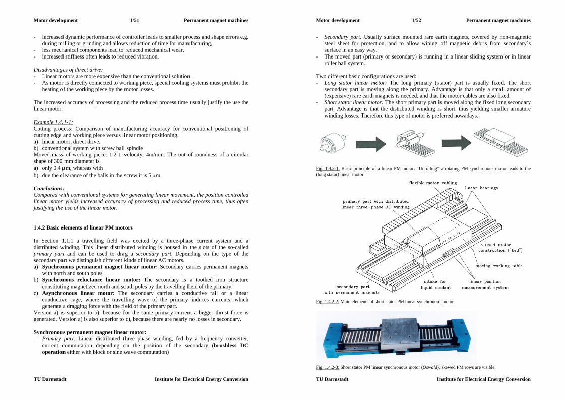
Motor development 1/51 Permanent magnet machines
TU Darmstadt Institute for Electrical Energy Conversion
- increased dynamic performance of controller leads to smaller process and shape errors e.g. during milling or grinding and allows reduction of time for manufacturing,
- less mechanical components lead to reduced mechanical wear, - increased stiffness often leads to reduced vibration. Disadvantages of direct drive: - Linear motors are more expensive than the conventional solution. - As motor is directly connected to working piece, special cooling systems must prohibit the
heating of the working piece by the motor losses. The increased accuracy of processing and the reduced process time usually justify the use the linear motor. Example 1.4.1-1: Cutting process: Comparison of manufacturing accuracy for conventional positioning of cutting edge and working piece versus linear motor positioning. a) linear motor, direct drive, b) conventional system with screw ball spindle Moved mass of working piece: 1.2 t, velocity: 4m/min. The out-of-roundness of a circular shape of 300 mm diameter is a) only 0.4 m, whereas with b) due the clearance of the balls in the screw it is 5 m. Conclusions: Compared with conventional systems for generating linear movement, the position controlled linear motor yields increased accuracy of processing and reduced process time, thus often justifying the use of the linear motor. 1.4.2 Basic elements of linear PM motors In Section 1.1.1 a travelling field was excited by a three-phase current system and a distributed winding. This linear distributed winding is housed in the slots of the so-called primary part and can be used to drag a secondary part. Depending on the type of the secondary part we distinguish different kinds of linear AC motors. a) Synchronous permanent magnet linear motor: Secondary carries permanent magnets
with north and south poles b) Synchronous reluctance linear motor: The secondary is a toothed iron structure
constituting magnetized north and south poles by the travelling field of the primary. c) Asynchronous linear motor: The secondary carries a conductive rail or a linear
conductive cage, where the travelling wave of the primary induces currents, which generate a dragging force with the field of the primary part.
Version a) is superior to b), because for the same primary current a bigger thrust force is generated. Version a) is also superior to c), because there are nearly no losses in secondary. Synchronous permanent magnet linear motor: - Primary part: Linear distributed three phase winding, fed by a frequency converter,
current commutation depending on the position of the secondary (brushless DC operation either with block or sine wave commutation)
Motor development 1/52 Permanent magnet machines
TU Darmstadt Institute for Electrical Energy Conversion
- Secondary part: Usually surface mounted rare earth magnets, covered by non-magnetic steel sheet for protection, and to allow wiping off magnetic debris from secondary´s surface in an easy way.
- The moved part (primary or secondary) is running in a linear sliding system or in linear roller ball system.
Two different basic configurations are used: - Long stator linear motor: The long primary (stator) part is usually fixed. The short
secondary part is moving along the primary. Advantage is that only a small amount of (expensive) rare earth magnets is needed, and that the motor cables are also fixed.
- Short stator linear motor: The short primary part is moved along the fixed long secondary part. Advantage is that the distributed winding is short, thus yielding smaller armature winding losses. Therefore this type of motor is preferred nowadays.
Fig. 1.4.2-1: Basic principle of a linear PM motor: “Unrolling” a rotating PM synchronous motor leads to the (long stator) linear motor
Fig. 1.4.2-2: Main elements of short stator PM linear synchronous motor
Fig. 1.4.2-3: Short stator PM linear synchronous motor (Oswald), skewed PM rows are visible.
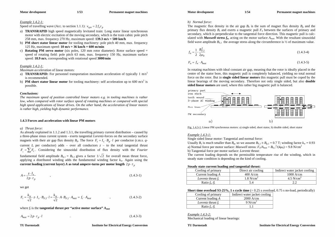
Motor development 1/53 Permanent magnet machines
TU Darmstadt Institute for Electrical Energy Conversion
Example 1.4.2-1: Speed of travelling wave (Acc. to section 1.1.1): pssyn fv 2 a) TRANSRAPID high speed magnetically levitated train: Long stator linear synchronous
motor with electric excitation of the moving secondary, which is the train cabin: pole pitch 258 mm, max. frequency 270 Hz, maximum speed: 139.3 m/s = 500 km/h
b) PM short stator linear motor for tooling machinery: pole pitch 40 mm, max. frequency 125 Hz, maximum speed: 10 m/s = 36 km/h = 600 m/min
c) Rotating PM servo motor (six poles, 120 mm rotor diameter): Rotor surface speed = speed of rotating field: pole pitch 63 mm, max. frequency 150 Hz, maximum surface speed: 18.9 m/s, corresponding with rotational speed 3000/min
Example 1.4.2-1: Maximum acceleration of linear motors: a) TRANSRAPID: For personnel transportation maximum acceleration of typically 1 m/s2
is recommended. b) PM short stator linear motor for tooling machinery: self acceleration up to 600 m/s2 is
possible. Conclusions: The maximum speed of position controlled linear motors e.g. in tooling machines is rather low, when compared with rotor surface speed of rotating machines or compared with special high speed applications of linear drives. On the other hand, the acceleration of linear motors is rather high, yielding high dynamic performance. 1.4.3 Forces and acceleration with linear PM motors a) Thrust force: As already explained in 1.1.2 and 1.3.1, the travelling primary current distribution – caused by a three-phase sinus current system - exerts tangential Lorentz-forces on the secondary surface magnets with their air gap flux density Bp. The force lBIF psc per conductor (r.m.s. q-current Is per conductor) adds – over all conductors z – to the total tangential thrust
cFFt
. Considering the sinusoidal distribution of flux density with the Fourier
fundamental field amplitude Bp,1 = B,1 gives a factor 2/1 for overall mean thrust force, applying a distributed winding adds the fundamental winding factor kw. Again using the current loading (current layer) A as total ampere-turns per motor length pp 2
p
sp
IzA
2 , (1.4.3-1)
we get
mottmotw
sw
t AfABAklBIzkF 1,1, 22 , (1.4.3-2)
where ft is the tangential thrust per “active motor surface” Amot
lpA pmot 2 . (1.4.3-3)
Motor development 1/54 Permanent magnet machines
TU Darmstadt Institute for Electrical Energy Conversion
b) Normal force: The magnetic flux density in the air gap B is the sum of magnet flux density Bp and the primary flux density Bs and exerts a magnetic pull Fn between the surfaces of primary and secondary, which is perpendicular to the tangential force direction. This magnetic pull is calc-ulated with Maxwell stress fn, acting on the motor surface Amot. With the resultant sinusoidal field wave amplitude B,1 the average stress along the circumference is ½ of maximum value.
0
21,
221
B
fn (1.4.3-4)
motnn AfF (1.4.3-5) In rotating machines with ideal constant air gap, meaning that the rotor is ideally placed in the centre of the stator bore, this magnetic pull is completely balanced, yielding no total normal force on the rotor. But in single sided linear motors this magnetic pull must be coped by the linear bearings of the moving secondary. Therefore not only single sided, but also double sided linear motors are used, where this rather big magnetic pull is balanced.
Fig. 1.4.3-1: Linear PM synchronous motors: a) single sided, short stator, b) double sided, short stator Example 1.4.3-1: Single sided linear motor: Tangential and normal force: Usually Bs is much smaller than Bp, so we assume B,1 Bp,1 = 0.7 T; winding factor kw = 0.93 a) Normal force per motor surface: Maxwell stress: Fn/Amot = B,1
2/(40) = 9.8 N/cm2 b) Tangential force per motor surface: Lorentz thrust: The current loading depends on the permissible temperature rise of the winding, which in steady state condition is depending on the kind of cooling. Steady state current loading and tangential thrust:
Cooling of primary Direct air cooling Indirect water jacket cooling Current loading A 400 A/cm 1000 A/cm Lorentz thrust ft 1.8 N/cm2 4.5 N/cm2
Ratio fn /ft 5.4 2.2 Short time overload S3-25%, 1 s cycle time (= 0.25 s overload, 0.75 s no-load, periodically)
Cooling of primary Indirect water jacket cooling Current loading A 2000 A/cm Lorentz thrust ft 9 N/cm2
Ratio fn /ft 1.1 Example 1.4.3-2: Mechanical loading of linear bearings:
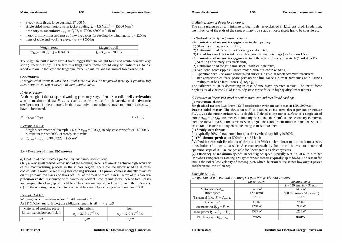
Motor development 1/55 Permanent magnet machines
TU Darmstadt Institute for Electrical Energy Conversion
- Steady state thrust force demand: 17 000 N, - single sided linear motor, water jacket cooling: ft = 4.5 N/cm2 (= 45000 N/m2) - necessary motor surface: 38.045000/17000/ ttmot fFA m2, - motor primary mass and mass of moving cables for feeding the winding: mmot = 220 kg - mass of table and working piece: mW+T = 1500 kg
Weight force Magnetic pull 16870)( gmm motTW N 37050 motn Af N
The magnetic pull is more than 4 times bigger than the weight force and would demand very strong linear bearings. Therefore this (big) linear motor would only be realized as double sided version. In that case the tangential force is doubled, and the normal force cancelled. Conclusions: In single sided linear motors the normal force exceeds the tangential force by a factor 5. Big linear motors therefore have to be built double sided. c) Acceleration: As the weight of the transported working piece may vary, often the so-called self acceleration a with maximum thrust Ft,max is used as typical value for characterizing the dynamic performance of linear motors. In that case only motor primary mass and motor cables mmot have to be moved.
mott mFa /max, (1.4.3-6) Example 1.4.3-3: - Single sided motor of Example 1.4.3-2: mmot = 220 kg, steady state thrust force: 17 000 N - Maximum thrust: 200% of steady state value
155220/34000/max, mott mFa m/s2 1.4.4 Features of linear PM motors a) Cooling of linear motors for tooling machinery application: Only a very small thermal expansion of the working piece is allowed to achieve high accuracy of the manufacturing process in the micron region. Therefore the motor winding is often cooled with a water jacket, using two cooling systems. The power cooler is directly mounted on the primary iron stack and takes off 85% of the total primary losses. On top of this cooler a precision cooler is mounted with controlled coolant flow, taking away 15% of total losses and keeping the changing of the table surface temperature of the linear drive within = 2 K (!). So the working piece, mounted on the table, sees only a change in temperature of 2 K. Example 1.4.4-1: Working piece: main dimension: l = 400 mm at 20°C At 22°C (when motor is hot) the additional length is ll
Material of working piece Aluminium Iron Linear expansion coefficient /108.23 6 K /100.12 6 K
l 19 m 10 m
Motor development 1/56 Permanent magnet machines
TU Darmstadt Institute for Electrical Energy Conversion
b) Minimization of thrust force ripple: The same measures as to minimize torque ripple, as explained in 1.1.8, are used. In addition, the influence of the ends of the short primary iron stack on force ripple has to be considered. (i) No-load force ripple (current is zero): - Minimization of magnetic cogging due to slot openings 1) Skewing of magnets or of slots, 2) Optimization of the ratio slot opening vs. slot pitch, 3) Use of fractional slot windings such as tooth wound windings (see Section 1.5.2) - Minimization of magnetic cogging due to both ends of primary iron stack (“end effect”) 1) Skewing of primary iron stack ends, 2) Optimization of the ratio iron stack length vs. pole pitch, (ii) Additional force ripple at loaded motor (current flow in winding): - Operation with sine wave commutated currents instead of block commutated currents - star connection of three phase primary winding cancels current harmonics with 3-times
multiples of basic frequencies 3fs, 6fs, 9fs, ... The influence of (i) is dominating in case of sine wave operated motors. The thrust force ripple is usually below 2% of the steady state thrust force in high quality linear motors. c) Features of linear PM synchronous motors with indirect liquid cooling: (i) Maximum thrust: Single sided motor: 5...8 N/cm2. Self acceleration (without cable mass): 150...300m/s2. Double sided motor: The thrust force Ft is doubled at the same thrust per motor surface Ft/Amot , as the motor surface Amot is doubled. Related to the motor surface of a single sided motor Amot = 2pplFe this means a doubling of ft : 10...16 N/cm2. If the secondary is moved, then the moved mass is the same as with single sided motor, but thrust is doubled. So self-acceleration is increased by 200%, reaching values of 600 m/s2. (ii) Steady state thrust: It is typically 50% of maximum thrust, so the overload capability is 200%. (iii) Maximum speed: up to 600m/min = 36 km/h (iv) Position control: Resolution of the position: With modern linear optical position sensors a resolution of 1 nm is possible. Accurate repeatability for control is less; for controlled operation steps of 0.5 m are possible for linear precision drive systems. (v) Efficiency at maximum speed: Depending on speed typically 60% to 70%, thus rather low when compared to rotating PM synchronous motors (typically up to 95%). The reason for this is the rather low velocity of moving part, which determines the rather low output power and therefore low efficiency. Example 1.4.4-2: Comparison of a linear and a rotating six pole PM synchronous motor:
Linear motor Rotating motor dr = 120 mm, lFe = 37 mm
Motor surface Amot 140 cm2 140 cm2 Rated speed 120 m/min 1500/min (v = 565 m/min)
Tangential force tmott fAF 630 N 630 N
Frequency fs 16 Hz 75 Hz Output power vFPout 1260 W 5930 W
Input power Cuoutin PPP 1585 W 6255 W
Efficiency inout PP / 79.5% 94.8%
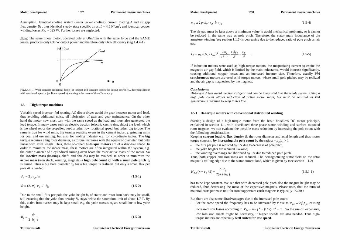
Motor development 1/57 Permanent magnet machines
TU Darmstadt Institute for Electrical Energy Conversion
Assumption: Identical cooling system (water jacket cooling), current loading A and air gap flux density B , thus identical steady state specific thrust ft = 4.5 N/cm2, and identical copper winding losses PCu = 325 W. Further losses are neglected. Note: The same linear motor, operated only at 60m/min with the same force and the SAME losses, produces only 630 W output power and therefore only 66% efficiency (Fig.1.4.4-1).
Fig.1.4.4.-1: With constant tangential force (or torque) and constant losses the output power Pout decreases linear with rotational speed n (or linear speed v), causing a decrease of the efficiency 1.5 High torque machines Variable speed inverter- fed rotating AC direct drives avoid the gear between motor and load, thus avoiding additional noise, oil lubrication of gear and gear maintenance. On the other hand the motor now must turn with the same speed as the load and must also generated the load torque. In many cases such as electric traction (electric cars, trains, ships) the load, which is the wheel set or the propeller, need a rather low rotational speed, but rather big torque. The same is true for wind mills, big turning roasting ovens in the cement industry, grinding mills for coal and ore mining, but also for tooling industry e.g. for co-ordinate tables. The big torque requires a big rotor diameter, as torque increases with the square of diameter, but only linear with axial length. Thus, these so-called hi-torque motors are of a disc-like shape. In order to minimize the motor mass, these motors are often integrated within the system, e.g. the outer diameter of a cylindrical turning oven bears the rotor active mass of the motor. So the inactive mass (bearings, shaft, end shields) may be avoided. In order to mimimize the active mass (iron stack, winding, magnets) a high pole count 2p with a small pole pitch p is aimed. Thus a big bore diameter dsi for a big torque is realized, but only a small flux per pole is needed.
/2 psi pd (1.5-1)
Blp )/2( (1.5-2) Due to the small flux per pole the yoke height hy of stator and rotor iron back may be small, still ensuring that the yoke flux density By stays below the saturation limit of about 1.7 T. By this, active iron masses may be kept small, e.g. the yoke masses my are small due to low yoke height.
lhB
yy
2 (1.5-3)
Motor development 1/58 Permanent magnet machines
TU Darmstadt Institute for Electrical Energy Conversion
Fepyy lhpm 2 (1.5-4) The air gap must be kept above a minimum value to avoid mechanical problems, so it cannot be reduced in the same way as pole pitch. Therefore, the stator main inductance of the armature winding (see section 1.1.5) is decreasing due to the reduced ratio of pole pitch vs. air gap.
pFeps
wsshl
pmkNL ~2)( 2
20
. (1.5-5)
If induction motors were used as high torque motors, the magnetizing current to excite the magnetic air gap field, which is limited by the main inductance, would increase significantly, causing additional copper losses and an increased inverter size. Therefore, usually PM synchronous motors are used as hi-torque motors, where small pole pitches may be realized and the air gap is magnetized by the magnets. Conclusions: Hi-torque drives avoid mechanical gear and can be integrated into the whole system. Using a high pole count allows reduction of active motor mass, but must be realized as PM synchronous machine to keep losses low. 1.5.1 Hi-torque motors with conventional distributed winding Starting a design of a high-torque motor from the basic brushless DC motor principle, explained in section 1.1, with distributed three-phase stator winding and surface mounted rotor magnets, we can evaluate the possible mass reduction by increasing the pole count with the following considerations. Keeping current load A, flux density B, the rotor diameter and axial length and thus motor torque constant, by increasing the pole count by the ratio x = p2/p1 > 1 - the flux per pole is reduced by 1/x due to decrease of pole pitch, - the yoke heights are reduced likewise, - the winding overhangs are shortened by 1/x due to reduced pole pitch. Thus, both copper and iron mass are reduced. The demagnetizing stator field on the rotor magnet´s trailing edge due to the stator current load, which is given by (see section 1.1.2)
)(2)2/(,
M
pps h
AxH
(1.5.1-1)
has to be kept constant. We see that with decreased pole pitch also the magnet height may be reduced, thus decreasing the mass of the expensive magnets. Please note, that the ratio of material costs per mass unit for iron/copper/rare earth magnets is typically 1/2/30 ! But there are also some disadvantages due to the increased pole count: - For the same speed the frequency has to be increased by x due to pssyn fv 2 , causing
increased iron losses according to xxxfmPFe 22 )/1(~~ . So the use of expensive, low loss iron sheets might be necessary, if higher speeds are also needed. Thus high-torque motors are especially well suited for low speed.
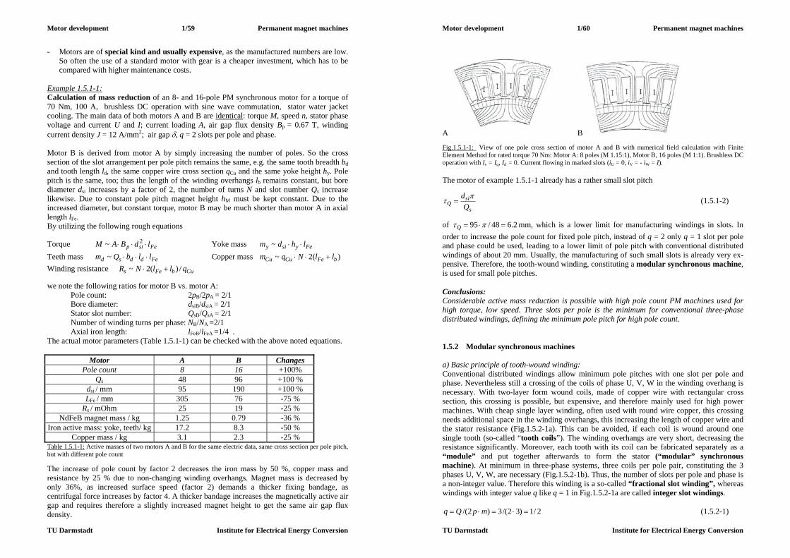
Motor development 1/59 Permanent magnet machines
TU Darmstadt Institute for Electrical Energy Conversion
- Motors are of special kind and usually expensive, as the manufactured numbers are low. So often the use of a standard motor with gear is a cheaper investment, which has to be compared with higher maintenance costs.
Example 1.5.1-1: Calculation of mass reduction of an 8- and 16-pole PM synchronous motor for a torque of 70 Nm, 100 A, brushless DC operation with sine wave commutation, stator water jacket cooling. The main data of both motors A and B are identical: torque M, speed n, stator phase voltage and current U and I; current loading A, air gap flux density Bp = 0.67 T, winding current density J = 12 A/mm2; air gap , q = 2 slots per pole and phase. Motor B is derived from motor A by simply increasing the number of poles. So the cross section of the slot arrangement per pole pitch remains the same, e.g. the same tooth breadth bd and tooth length ld, the same copper wire cross section qCu and the same yoke height hy. Pole pitch is the same, too; thus the length of the winding overhangs lb remains constant, but bore diameter dsi increases by a factor of 2, the number of turns N and slot number Qs increase likewise. Due to constant pole pitch magnet height hM must be kept constant. Due to the increased diameter, but constant torque, motor B may be much shorter than motor A in axial length lFe. By utilizing the following rough equations
Torque Fesip ldBAM 2~ Yoke mass Feysiy lhdm ~ Teeth mass Feddsd llbQm ~ Copper mass )(2~ bFeCuCu llNqm Winding resistance CubFes qllNR /)(2~ we note the following ratios for motor B vs. motor A:
Pole count: 2pB/2pA = 2/1 Bore diameter: dsiB/dsiA = 2/1 Stator slot number: QsB/QsA = 2/1 Number of winding turns per phase: NB/NA =2/1
Axial iron length: lFeB/lFeA =1/4 . The actual motor parameters (Table 1.5.1-1) can be checked with the above noted equations.
Motor A B Changes Pole count 8 16 +100%
Qs 48 96 +100 % dsi / mm 95 190 +100 % LFe / mm 305 76 -75 %
Rs / mOhm 25 19 -25 % NdFeB magnet mass / kg 1.25 0.79 -36 %
Iron active mass: yoke, teeth/ kg 17.2 8.3 -50 % Copper mass / kg 3.1 2.3 -25 %
Table 1.5.1-1: Active masses of two motors A and B for the same electric data, same cross section per pole pitch, but with different pole count The increase of pole count by factor 2 decreases the iron mass by 50 %, copper mass and resistance by 25 % due to non-changing winding overhangs. Magnet mass is decreased by only 36%, as increased surface speed (factor 2) demands a thicker fixing bandage, as centrifugal force increases by factor 4. A thicker bandage increases the magnetically active air gap and requires therefore a slightly increased magnet height to get the same air gap flux density.
Motor development 1/60 Permanent magnet machines
TU Darmstadt Institute for Electrical Energy Conversion
A B Fig.1.5.1-1: View of one pole cross section of motor A and B with numerical field calculation with Finite Element Method for rated torque 70 Nm: Motor A: 8 poles (M 1.15:1), Motor B, 16 poles (M 1:1). Brushless DC operation with Is = Iq, Id = 0. Current flowing in marked slots (iU = 0, iV = - iW = I). The motor of example 1.5.1-1 already has a rather small slot pitch
s
siQ Q
d (1.5.1-2)
of 2.648/95 Q mm, which is a lower limit for manufacturing windings in slots. In order to increase the pole count for fixed pole pitch, instead of q = 2 only q = 1 slot per pole and phase could be used, leading to a lower limit of pole pitch with conventional distributed windings of about 20 mm. Usually, the manufacturing of such small slots is already very ex-pensive. Therefore, the tooth-wound winding, constituting a modular synchronous machine, is used for small pole pitches. Conclusions: Considerable active mass reduction is possible with high pole count PM machines used for high torque, low speed. Three slots per pole is the minimum for conventional three-phase distributed windings, defining the minimum pole pitch for high pole count. 1.5.2 Modular synchronous machines a) Basic principle of tooth-wound winding: Conventional distributed windings allow minimum pole pitches with one slot per pole and phase. Nevertheless still a crossing of the coils of phase U, V, W in the winding overhang is necessary. With two-layer form wound coils, made of copper wire with rectangular cross section, this crossing is possible, but expensive, and therefore mainly used for high power machines. With cheap single layer winding, often used with round wire copper, this crossing needs additional space in the winding overhangs, this increasing the length of copper wire and the stator resistance (Fig.1.5.2-1a). This can be avoided, if each coil is wound around one single tooth (so-called “tooth coils”). The winding overhangs are very short, decreasing the resistance significantly. Moreover, each tooth with its coil can be fabricated separately as a “module” and put together afterwards to form the stator (“modular” synchronous machine). At minimum in three-phase systems, three coils per pole pair, constituting the 3 phases U, V, W, are necessary (Fig.1.5.2-1b). Thus, the number of slots per pole and phase is a non-integer value. Therefore this winding is a so-called “fractional slot winding”, whereas windings with integer value q like q = 1 in Fig.1.5.2-1a are called integer slot windings.
2/1)32/(3)2/( mpQq (1.5.2-1)

Motor development 1/61 Permanent magnet machines
TU Darmstadt Institute for Electrical Energy Conversion
In Fig.1.5.2-1 the MMF distribution V(x) = H(x) and the corresponding flux density distribution B,s(x) is shown for the moment, when the phase currents are iU = 0, iV = - iW. This distribution is symmetrical to x-axis in case of integer slot winding (Fig.1.5.2-1b), but asymmetric in case of fractional slot winding (Fig.1.5.2-1a).
Fig.1.5.2-1: Magnetic flux density distribution and fundamental in a constant air gap: a) fractional slot winding q = ½, b) Integer slot winding q = 1, current flowing in marked slots (iU = 0, iV = - iW = I). b) Air gap space harmonics: Fourier-analysis therefore yields a spectrum of travelling waves with different wave lengths
/2 p (1.5.2-1) and MMF amplitudes Vs, and flux density amplitudes B,s,, which are decreasing with rising ordinal number . In the symmetric case only odd values occur, whereas in the asymmetric case both odd and even values occur. Due to the three phase system (m = 3) no values occur, which are divisible by factor 3. Integer slot winding: ,...13,11,7,5,1,...3,2,1,021 ggm
Fractional slot winding: 1,/ NNZ qqqq , ,...3,2,1,0/21 gqgm N For ,...13,11,10,8,7,5,4,2,1:2 Nq The sign of the ordinal number denotes the direction of rotation. As all waves are exited by stator current, oscillating with frequency fs, the wave speed is
sp
s ffv
2
(1.5.2-2) Thus waves with negative rotate counter-clockwise, whereas waves with positive rotate clockwise. The fundamental wave = 1 is the one, which produces the tangential force with the rotor magnet flux wave of the same wave length. For basic motor understanding, as done so far, the consideration of the fundamental space harmonic is sufficient. The other waves, so-called space harmonics, produce no constant tangential force with the permanent magnet flux
Motor development 1/62 Permanent magnet machines
TU Darmstadt Institute for Electrical Energy Conversion
distribution, as they are moving slower with increasing ordinal number, whereas the rotor permanent magnet flux distribution rotates with synchronous speed only. Thus, additional oscillating parasitic torque is generated, which has been discussed already in 1.1.8 as load torque ripple. We have to conclude that the amount of oscillating torque may increase with fractional slot winding due to the increase of space harmonics. The magnetic pull of these space harmonics is also oscillating and might cause the stator and rotor construction to vibrate. Usually the cylindrical shell-like stator yoke and housing is less stiff than the rotor and more sensitive to vibrations. The vibrations may compress and decompress the surrounding air, thus generating acoustic sound (“magnetic noise”). Furthermore, the space harmonics, running asynchronously with respect to the rotor, may induce eddy currents in the conductive magnets and iron back, thus generating additional rotor losses even at ideal sinusoidal current supply. Conclusions: With tooth-wound coils of the modular synchronous machine a low stator resistance and a small pole pitch for high pole count is achieved at the expense of asymmetric stator air gap flux density distribution, which may give rise to additional load torque ripple, magnetic noise and additional rotor losses. c) Use of modular machines to increase pole count: The big advantage of modular machines is that the pole pitch may be decreased even further without the need of reducing slot pitch. In Fig. 1.5.2-3a the case for q = ¼ is shown, that means that three stator slots are opposed by 4 rotor magnet poles. The stator coil arrangement and therefore the MMF distribution is the same as for q = ½ (Fig.1.5.2-3b), but now the rotor pole pitch does not fit with the wave length of the stator wave = 1, but for = -2. That means that the rotor will rotate synchronously not with the stator fundamental wave, but with the first space harmonic, thus a 50% speed and in counter-clockwise direction. The fundamental will generate a pulsating torque with the rotor magnets, which has to be sustained.
Example 1.5.2-1: Gearless direct drive with 28 poles for light rail vehicles such as metros (Fig.1.5.2-2) Rated output power PN per motor 250 kW Rated/maximum rotational speed nN per wheel set 398 /min / 772 /min Rated torque MN per wheel set: low vs. maximum speed 6000 Nm / 3094 NmDC link voltage Ud 750 V Rated phase voltage UN (rms), sine-wave 338 V Overall outer /inner diameter da / dsi 390 mm / 282 mmAir gap + bandage: + dB 1.34 mm Pole pitch p & magnet height hmag & stack length lFe 31.64 mm & 7 mm & 975 mm Two different designs with tooth-wound coils are shown in Fig. 1.5.2-3: q = 1/4 and q =1/2.
Fig.1.5.2-2: Cross section of a direct drive modular synchronous machine with the rotor directly mounted on the axle shaft of a metro wheel set

Motor development 1/63 Permanent magnet machines
TU Darmstadt Institute for Electrical Energy Conversion
Fig.1.5.2-3: Modular synchronous machine: Numerically calculated magnetic flux density distribution at no-load (current is zero) for 2 pole pairs of PM synchronous machines with tooth-wound fractional slot winding: a) q = ¼ ( with 4 mm narrow inter-tooth to separate tooth coils), b) q =1/2 (no inter-tooth used) The wave length of the stator fundamental defines the basic scheme of a stator winding arrangement. This can be repeated periodically, e.g. four times. With the number of zS = 7 basic schemes we get in Fig.1.5.2-3a 2137 slots and 2874 poles. Per basic scheme in Fig.1.5.2-3 the number of slots and rotor poles differs by one. This configuration is often used to design modular synchronous machines. For this case we get the number of poles by
)1(2 mQzp MS , (1.5.2-3) with QM being the number of slots per module. d) Application of modular motors: The fractional slot winding with tooth-coils is used not only for high torque rotating machines, but also extensively for linear PM motors and for standard PM brushless DC servo drives. The main feature is that the rotor has surface mounted magnets. Due to this fact the magnetically active air gap MBres hd is rather big, yielding only very small space harmonic amplitudes:
res
ss
VB
,
0, (1.5.2-4)
In induction machines with their small air gap the space harmonic amplitudes would be rather big, causing big additional harmonic currents in the short circuited rotor winding with big additional losses. Therefore, these fractional slot windings have to be used very carefully only with those rotor configurations, where the influence of space harmonics is kept small. Example 1.5.2-2: Wheel-hub motor for military vehicle (Fig.1.5.2-4) An outer rotor construction is chosen to be fixed directly to the wheel. A big torque is needed to accelerate the vehicle from stand-still. Therefore, a modular synchronous machine is well suited. For increased safety a five phase system is chosen, feeding the five winding legs from
Motor development 1/64 Permanent magnet machines
TU Darmstadt Institute for Electrical Energy Conversion
five independent single-phase inverters. If one of the phases fails, the other four will still produce a travelling field to drive the rotor, even when starting from stand still. Please note, that a three phase system with one phase failed will not produce a travelling field any longer, but only a pulsating air gap field: So no starting from stand still is possible in case of a failure. Number of basic schemes: 2Sz , number of slots per module: 1MQ , number of phases: m = 5 (a ... e); number of slots: 10 MSs QmzQ number of poles: 12)151(2)1(2 mQzp MS
Fig.1.5.2-4: Modular outer rotor synchronous motor as a wheel hub drive, operated with 5 phases a, b, c, d, e (PhD thesis Kolletschke, Uni Bundeswehr, Munich)
a) b) Fig.1.5.2-5: High torque motor with tooth-wound coils: a) stator with tooth coils, b) complete motor with water jacket cooling (Note spiral slot in stator housing for water flow), Siemens AG, Germany.
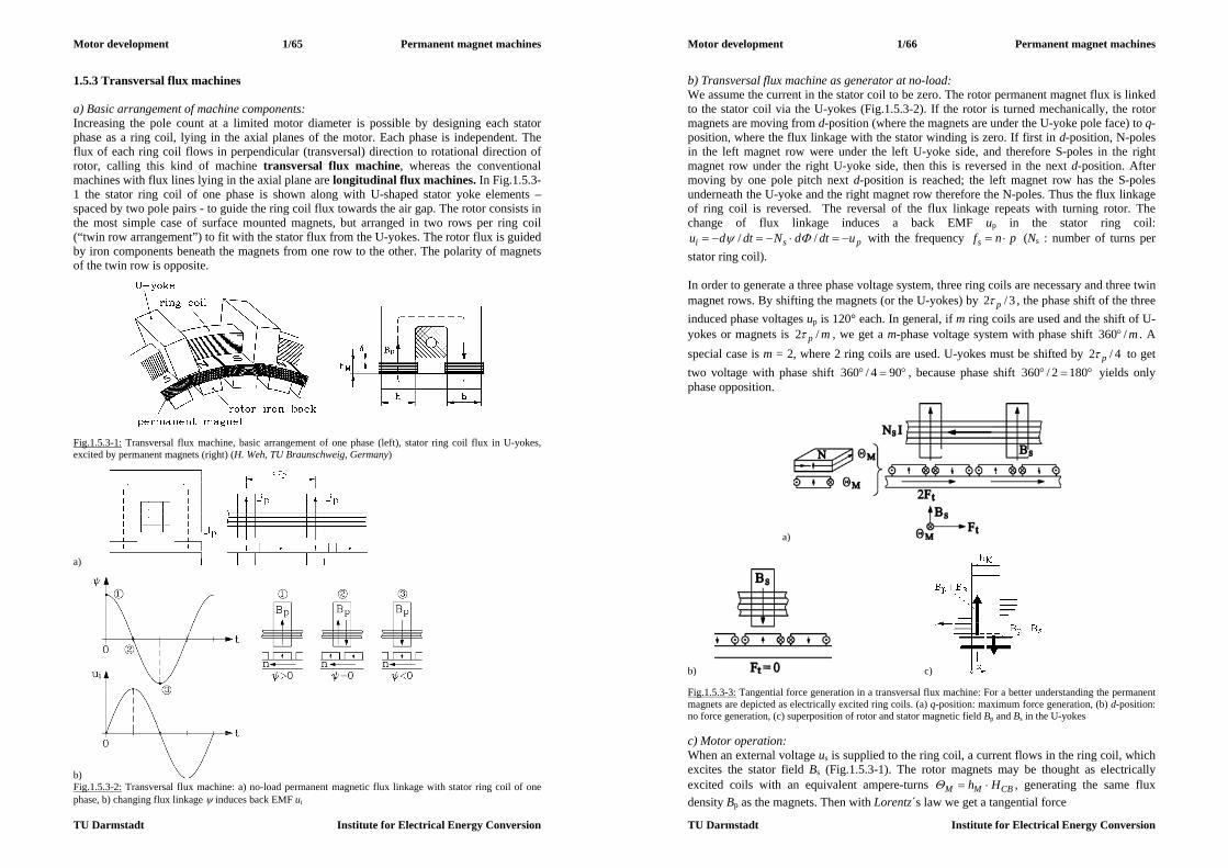
Motor development 1/65 Permanent magnet machines
TU Darmstadt Institute for Electrical Energy Conversion
1.5.3 Transversal flux machines a) Basic arrangement of machine components: Increasing the pole count at a limited motor diameter is possible by designing each stator phase as a ring coil, lying in the axial planes of the motor. Each phase is independent. The flux of each ring coil flows in perpendicular (transversal) direction to rotational direction of rotor, calling this kind of machine transversal flux machine, whereas the conventional machines with flux lines lying in the axial plane are longitudinal flux machines. In Fig.1.5.3-1 the stator ring coil of one phase is shown along with U-shaped stator yoke elements – spaced by two pole pairs - to guide the ring coil flux towards the air gap. The rotor consists in the most simple case of surface mounted magnets, but arranged in two rows per ring coil (“twin row arrangement”) to fit with the stator flux from the U-yokes. The rotor flux is guided by iron components beneath the magnets from one row to the other. The polarity of magnets of the twin row is opposite.
Fig.1.5.3-1: Transversal flux machine, basic arrangement of one phase (left), stator ring coil flux in U-yokes, excited by permanent magnets (right) (H. Weh, TU Braunschweig, Germany)
a)
b) Fig.1.5.3-2: Transversal flux machine: a) no-load permanent magnetic flux linkage with stator ring coil of one phase, b) changing flux linkage induces back EMF ui
Motor development 1/66 Permanent magnet machines
TU Darmstadt Institute for Electrical Energy Conversion
b) Transversal flux machine as generator at no-load: We assume the current in the stator coil to be zero. The rotor permanent magnet flux is linked to the stator coil via the U-yokes (Fig.1.5.3-2). If the rotor is turned mechanically, the rotor magnets are moving from d-position (where the magnets are under the U-yoke pole face) to q-position, where the flux linkage with the stator winding is zero. If first in d-position, N-poles in the left magnet row were under the left U-yoke side, and therefore S-poles in the right magnet row under the right U-yoke side, then this is reversed in the next d-position. After moving by one pole pitch next d-position is reached; the left magnet row has the S-poles underneath the U-yoke and the right magnet row therefore the N-poles. Thus the flux linkage of ring coil is reversed. The reversal of the flux linkage repeats with turning rotor. The change of flux linkage induces a back EMF up in the stator ring coil:
psi udtdNdtdu // with the frequency pnfs (Ns : number of turns per stator ring coil). In order to generate a three phase voltage system, three ring coils are necessary and three twin magnet rows. By shifting the magnets (or the U-yokes) by 3/2 p , the phase shift of the three induced phase voltages up is 120° each. In general, if m ring coils are used and the shift of U-yokes or magnets is mp /2 , we get a m-phase voltage system with phase shift m/360 . A special case is m = 2, where 2 ring coils are used. U-yokes must be shifted by 4/2 p to get two voltage with phase shift 904/360 , because phase shift 1802/360 yields only phase opposition.
a)
b) c) Fig.1.5.3-3: Tangential force generation in a transversal flux machine: For a better understanding the permanent magnets are depicted as electrically excited ring coils. (a) q-position: maximum force generation, (b) d-position: no force generation, (c) superposition of rotor and stator magnetic field Bp and Bs in the U-yokes c) Motor operation: When an external voltage us is supplied to the ring coil, a current flows in the ring coil, which excites the stator field Bs (Fig.1.5.3-1). The rotor magnets may be thought as electrically excited coils with an equivalent ampere-turns CBMM Hh , generating the same flux density Bp as the magnets. Then with Lorentz´s law we get a tangential force

Motor development 1/67 Permanent magnet machines
TU Darmstadt Institute for Electrical Energy Conversion
hBF sMMt , (1.5.3-1) per pole magnet per row, when the magnet is in q-position, meaning that the gap between two adjacent pole magnets is centred under the U-yoke pole face. In d-position the magnetic equivalent ampere-turns are outside of the stator field, and no force is generated. In the stator coils flows the AC current with a frequency pnfs . At q-position maximum current must occur, whereas in d-position the current can be zero. This is the already discussed q-current operation of brushless DC machines. After movement of the rotor by one pole pitch, negative current amplitude with the rotor magnet of opposite polarity again produces positive tangential force (Fig.1.5.3-4). Thus the force pulsates with double stator frequency.
Fig.1.5.3-4: AC current produces positive (pulsating) tangential force in one phase of a transversal flux machine This can also be understood by considering the internal power of one coil, which is determined by back EMF and current:
)()2cos(12
ˆˆ)sin(ˆ)sin(ˆ)()()( tFvt
IUtItUtitutp tsyns
spssspp (1.5.3-2)
As in any single phase system, power and therefore force is consisting of an average value and an oscillating part with twice frequency. As the ring coils-magnet systems of the other phases operate with voltage and current phase shifted by 2/m, the total tangential rotor force is constant, given by the sum average force values per phase, whereas the oscillating parts are cancelling.
syn
spt v
IUmF
2
ˆˆ sp
ssite IUmpdFM
)2/( (1.5.3-3)
Thus torque has the same formula as at conventional PM machines. As the stator field also induces a voltage sss IL due to self-induction in the ring coil, where Ls is the inductance of the coil, we finally get –along with the resistive voltage drop - the voltage equation for each ring coil, which is the same as with conventional PM synchronous machines. Thus we understand that the transversal flux machine is a special kind of PM synchronous machine, which delivers maximum torque if it is operated with a position sensor as a brushless DC drive with sine wave commutated q-current.
psssss UIjXIRU (1.5.3-4)
Motor development 1/68 Permanent magnet machines
TU Darmstadt Institute for Electrical Energy Conversion
In Fig.1.5.3-3c the superposition of stator and rotor field in U-yoke is shown. On the left side the flux is increased to ps BB , on the right side it is decreased to ps BB . So the left side will saturate strongly, thus limiting the total flux density and the power output of the machine. Tangential force generation can also be understood by considering this resulting magnetic field. On the left side in the U-yoke it is increased, on the right side decreased. So the tangential magnetic force on the left side is bigger than on the right side, therefore a tangential magnetic pull will drag the rotor from left to right. This is the same result as with consideration of Lorentz-force on magnetic equivalent ampere-turns in Fig.1.5.3-3a. Conclusions: The transversal flux machine is a special kind of PM synchronous machine with a high pole count, as no slots are necessary. As coil cross section and flux cross section lie in perpendicular planes (transversal arrangement), the coil cross section may be increased without influencing the magnetic flux path. This is a big advantage compared to longitudinal machines. There, increase of coil cross section means increase of slot area, thus reducing tooth area, where magnetic flux is passing. Narrower teeth mean increased tooth flux density and increased iron saturation. Therefore the flux must be reduced to avoid extensive saturation. Hence in longitudinal machines areas for flux and current flow are dependent from each other, whereas in transversal flux machines they can be chosen independently. d) Rotor magnetic flux concentration: Instead of using surface mounted magnets, it is possible to use buried magnets in order to increase air gap flux density and to reduce permanent magnet material (Fig.1.5.3-5). So we get a symmetric arrangement, which allows a double sided ring coil arrangement. Hence the tangential force is generated twice, thus doubling the torque.
Fig.1.5.3-5: Magnetic flux concentration inside the rotor of a transversal flux machine in order to increase the air gap flux density and to allow a double sided ring coil arrangement (left); schematic of flux concentration with main dimensions (right) (H. Weh, TU Braunschweig, Germany) Theoretical flux concentration is given by the ratio of both permanent magnet surfaces versus the pole pitch surface:
12)(2 p
M
MMpMM
bBBkhBhbB
(1.5.3-5)

Motor development 1/69 Permanent magnet machines
TU Darmstadt Institute for Electrical Energy Conversion
So magnet breadth bM must be at least bigger than half the pole pitch to get flux concentration inside the air gap. By using Ampere´s law for assumed )0( FeFe H at no-load (current is zero) we get
MM
MMC
HhHBhHHsdH 2
0)2(2 00
. (1.5.3-6)
Combining it with the BM(HM)-characteristic of the permanent magnet in the second quadrant
RMMM BHB , (1.5.3-7) we finally get with (1.5.3-5) for no-load air-gap flux density pBIB )0( :
M
M
M
R
hk
BB
0
21
. (1.5.3-8)
In Fig.1.5.3-6 a 2D numerical field calculation is shown for d- and q-position of the rotor to calculate real flux concentration. Left, in d-position, current and force are zero. So we get the conditions assumed for the derivation of (1.5.3-8). But we see that a considerable part (23%) of the rotor permanent magnet flux is leaving the rotor downwards, thus reducing the flux available for concentration. Only 77% of magnet breadth bM delivers its flux to the upward air gap. Hence the concentration factor decreases: pMM bk /277.0 .
Fig.1.5.3-6: Real flux concentration (2D numerical field calculation): left: d-position of rotor: stator current and tangential force is zero, (right) q-position, maximum current and force Example 1.5.3-1: Theoretical increase of the air gap-flux density by flux concentration for the following data:
Motor development 1/70 Permanent magnet machines
TU Darmstadt Institute for Electrical Energy Conversion
4/ Mh , 05.1/ 0 M , BR = 1.1 T.
No flux concentration
Flux concentration No stray flux
Flux concentration Stray flux 23%
Concentration factor kM 1 3.4 6.24.377.0 pBIB )0( 0.72 T 1.34 T (+85%) 1.21 T (+68%)
By using a concentration factor of 3.4, an increase of the air gap flux density by a factor of 1.85 is theoretically possible. Considering 2D rotor stray flux of 23% of PM flux, this concentration increase is reduced to factor 1.68. Possible flux increase is limited, because under load the stator field Bs is added in the U-yoke. The total flux density then should not exceed 2.0 T to avoid extensive iron saturation. The flux line pattern of Fig.1.5.3-6 leads again to understanding of force generation by considering the magnetic pull. Imagining the flux lines as elastic rubber strings, in d-position this pull is symmetric to left and right side, yielding total force value zero. In q-position the pull on rotor on left side of U-yokes is bigger than on right side. Thus a total tangential force exists, moving the rotor to the right. e) Electromagnetic utilization of transversal flux machines: Now we want to calculate power output of a simplified single sided transversal flux machine. We assume the pole width of the U-yoke bP equal to the pole pitch p and neglect the magnet height hM. Then the flux density pBIB )0( in d-position (Fig.1.5.3-7a, time t = 0) is constant along the pole pitch, yielding the pole flux
)( ppp hB . (1.5.3-9) The flux is linked to the ring coil p times (in p U-yokes), yielding a flux linkage
psNp . This maximum flux linkage decreases linear, when the rotor is moving and is zero in q-position (t = T/4) and negative maximum at t = T/2. Faraday´s law yields for induced voltage dtdui / a rectangular oscillating induced voltage, oscillating with
ss f 2 (T = 1/fs), with the amplitude (Fig.1.5.3-7b)
ppssi BhfNpT
U
222/
2ˆ . (1.5.3-10)
Considering the voltage fundamental 2ˆˆ
1)1( pii UUkU (here: /41 k ) according to Fourier analysis as ideal sinus back EMF, the internal power of transversal machines with q-current operation Is = Iq is derived:
2221 sppsssp IBhfpNkmIUmP . (1.3.5-11) As with longitudinal flux machines in Section 1.3, we consider the power per speed
pfn s / and active rotor volume (Esson´s number C), which is proportional to torque per
rotor volume. Rotor volume is (neglecting 4/ ) given as Fesild 2 . With psi pd 2 and hmlFe 2 for all m phases we get

Motor development 1/71 Permanent magnet machines
TU Darmstadt Institute for Electrical Energy Conversion
pp
ss
FesiBkIN
ldnPC 1
2
2 22
(1.3.5-12)
a) b) Fig.1.5.3-7: Ideal transversal flux machine: a) Permanent magnet flux linkage of the ring coil at d-position of the rotor (time t = 0), b) changing of the flux linkage, when the rotor is moving, induced rectangular shaped coil voltage and its fundamental Comparing this with C for longitudinal machines (section 1.3.1)
BAkC w 2
2 we see:
The concentrated ring coil of a transversal flux machine (TFM) has the winding factor kW = 1, and we can take pBk1 as equivalent amplitude of a sinusoidal distributed flux density to get an ideal sine wave back EMF. Most interesting is that for the transversal flux machine we have to take the current loading
p
ssINA2
(single sided TFM), p
ssINA2
2 (double sided TFM) (1.3.5-13)
As the ring coil with its ampere-turns NsIs passes all U-yokes, which are distanced by 2p, the current loading per U-yoke is NsIs/(2p), thus explaining the result (1.3.5-12) easily. When comparing A of TFM with that one of the longitudinal flux machine (LFM) (Section 1.3.1)
p
ss
si
sp
INmd
IzA 2
2
(1.3.5-14)
we see, that for LFM all phases contribute, whereas for TFM each phase acts independently. Most important is, that with the increase of pole count and simultaneous decrease of pole pitch the current loading and therefore motor output power remains constant for the LFM, but not for the TFM. As A for the TFM does not depend on the pole count, with decreasing pole pitch (= increasing pole count) current loading increases and thus the internal power, too. This can be easily understood. Tangential force per pole magnet hBF sMMt , is added to the total force summing all force contributions of U-yokes. So, with an increasing number of poles and therefore increasing number of all U-yokes we increase force and therefore torque and power.
hBpmFF sMMtt 2, (1.3.5-14)
Motor development 1/72 Permanent magnet machines
TU Darmstadt Institute for Electrical Energy Conversion
Of course, by reducing the pole pitch at a very small pole pitch (below about 20 mm) also the magnet height has to be reduced (Fig.1.3.5-6), so Bp decreases, and the motor loses power. Thus we get an optimum for the pole pitch of theoretically 10 ... 15 mm (Fig.1.3.5-8), which is derived by numerical field calculation.
Fig.1.5.3-8: Increase of power of a TFM at a given motor diameter and length by increasing the pole count (decreasing the pole pitch p) with a theoretical optimum pole pitch at about 10 ... 15 mm Example 1.5.3-2: Steady state internal power of single sided small 2-phase TFM (bore diameter dsi = 167 mm): Data: 2p = 30, p = 17.5 mm, = 0.8 mm, h = 28 mm, hM = 6.5 mm, bM = 18 mm,
m = 2, M/0 =1.05, BR = 1.095 T, stray flux: 30%, k1 = 1.07, Ns = 22 indirect cooling of the ring coil, current density: 4.6 A/mm2, nominal current Is = 95 A
speed n = 900/min a) Internal power:
22515)60/900( pnfs Hz
44.15.17
)3.01(182)3.01(2
p
MM
bk
15.1
5.68.0205.1
44.11
095.121
0
M
M
M
Rp
hk
BB
T
3.16715.1028.020175.02252221522ˆ ppssi BhfNpU V
1793.16707.1ˆˆ1)1( ii UkU V
2495)2/179(2 spIUmP kW c) Steady state utilization of a TFM:
60075.129522
2
p
ssINA
A/cm
515000)15.107.1(6000022
2
1
2
pBkAC Ws/m3 = 8.6kVAmin/m3
Compared to the results of longitudinal flux machines, Example 1.3.1-1b) we get 75% higher utilization. Conclusions: The transversal flux machine has a high torque per volume ratio, if the pole count is high, yielding an optimum pole pitches of typically 10...15 mm. Thus the TFM is well suited for low

Motor development 1/73 Permanent magnet machines
TU Darmstadt Institute for Electrical Energy Conversion
speed, high torque applications as direct drive. Utilization can be increased by a factor of about 2 compared to longitudinal flux machines. f) Performance and technology of transversal flux machines: In order to judge the technical value of transversal flux machines, one has to regard: - electromagnetic performance, concerning power output and losses - manufacturing (motor technology) - inverter rating. Electromagnetic performance: - No-load losses: The U-yokes experience iron losses due to changing flux linkage. The
numerically calculated flux plots show rather big stray flux already at no-load. With a rotating rotor this flux causes already at no-load eddy currents in metallic parts, such as end shields, cooling ducts, and in those ring coil copper wires, which are adjacent to the air gap. Eddy currents act along with this stray flux as an eddy current brake and reduce the possible shaft torque. In the rotor the PM flux has to change direction to the upper and lower U-yoke with stator frequency, causing additional eddy current losses in rotor iron and rotor magnets. These losses are dominating over friction losses.
- Load losses: At load the stator field adds to the stator iron losses and rotor magnet and iron losses, whereas the resistive losses in the ring coils are small. The ring coils are very compact and therefore have a low ohmic resistance.
- Tangential force usually per phase is not pulsating with an ideal sine, so over all phases the force and torque ripple is not cancelling totally, leading to a torque ripple with the frequency mnpf 2 . At the same time a radial magnetic pull between U-yokes and the rotor occurs, which is also pulsating with that frequency, causing radial vibrations of the stator and rotor, which might lead – especially in case of mechanical resonance with the natural frequency of the stator housing – to considerable magnetic noise.
Motor technology: - Flux concentration and buried rotor magnets are necessary to increase flux density in the
air gap, which is possible up to 1.5 T, as no tooth-slot-structure will cause further fringing. Only under load the additional stator flux in the U-yoke must be considered. The composite rotor consists of different components: laminated iron, permanent magnets, glass fibre construction to fix the magnet rows to the shaft and glue to fix the magnets. Due to different thermal expansion coefficients the rotor is mechanically sensitive to large changes in temperature.
- Rotor iron between the magnets must be laminated, as the permanent magnet flux is pulsating between upper and lower U-yokes (see Fig.1.5.3-6).
- Each phase is an electrically and mechanically independent module. So power may be increased by stacking more modules on one shaft. On the other hand, the pulsating forces of each single phase are acting on the rotor fixation, which must endure this stress.
- As the TFM has many poles, the stator frequency is rather high, if higher speed range is wanted. With frequencies up to 2000 Hz the U-yokes must be manufactured of very low loss iron sheet (0.1 mm thickness). As flux is not rotating within the sheets, low loss Hi-B-transformer iron sheets with losses of only 0.3 W/kg (at 1 T, 50 Hz) may be used. Another possibility is the use of the rather new material “soft magnetic composite”, which is a pressed structure of small iron grains, insulated by plastic encapsulation. Thus eddy currents are suppressed very well, but due to the plastic content the permeability is rather low (typical values 0500 ).
Motor development 1/74 Permanent magnet machines
TU Darmstadt Institute for Electrical Energy Conversion
Fig.1.5.3-9: Two phase prototype TFM (Univ. Brunswick, Prof. Weh): motor components and cross section
Fig.1.5.3-10: Two phase TFM demands a full bridge per phase Inverter technology: - In order to simplify the rotor construction, only three and two phase machines are used.
Three phase machines allow the use of conventional IGBT voltage source inverters (six IGBTs, six free-wheeling diodes on the motor side) with brushless DC current control. A rotor position sensor is needed. For two phase machines special inverters are necessary: Each phase is supplied by a full bridge inverter with 4 IGBTs and 4 free-wheeling diodes (Fig.1.5.3-10), which is more expensive than in three phase case. Upper and lower half bridge are chopping phase shifted, thus reducing the transistor switching frequency by factor 2 for a given pulse frequency at the coil terminals.
- At low speed the inverter is chopping the DC link voltage with a fixed switching frequency. With increased speed only six step mode (for three phases) or four step mode (for two phases) switching is applied, reducing the switching losses in the IGBTs. The back EMF is usually rather sinusoidal and dominates at elevated speed. So even with six or four step mode (= block shaped terminal voltage) the motor current is rather sinusoidal.
- Flux weakening for increased speed is possible by impressing Id current. With a buried magnet rotor the inductance of the stator coil is rather big, as the air gap between the U-yoke and the rotor may be kept small (< 1 mm). Hence the short circuit current is in the order of the rated current. So the necessary d-component of current for flux weakening can be easily supplied by the inverter.
- Due to the big stator inductance the power factor of the machine is rather low between 0.5 and 0.7. Hence the inverter needs a bigger current rating especially at low speed.
Conclusions: Rated current and short circuit current are nearly equal; the motor is flux weakened without overrating of the inverter. The power factor of about 0.75 is rather low due to the rather big inductance.

Motor development 1/75 Permanent magnet machines
TU Darmstadt Institute for Electrical Energy Conversion
g) Applications: Transversal flux machines are up to now not widely used. Small three phase motors exist as servo drives for positioning (Fig.1.5.3-13), but due to the strong curvature of the rotor at the small dimensions of about 100...150 mm outer diameter considerable stray flux reduces the power output. So the utilization of these motors is not bigger than of conventional longitudinal flux PM motors. Interesting applications for the TFM may be as direct drives in electric vehicles, street cars, trains, ships and wind-mills, where an increased motor diameter allows a high machine utilization. Prototypes have been built for several of these applications: - Three phase wheel-hub motors for street cars with about 45 kW power, - 500 kW prototype gearless drive for the ICE 3 high speed train, - Direct drives for city busses, where a diesel engine powers a TFM generator at constant
speed and optimum efficiency with minimized exhaustion and environmental pollution. The generator feeds inverters, which supply a wheel hub TFM for propelling the bus.
- Other projects deal with smaller motors for electric driven air planes, electric car drives, and larger ones with wind mill generators.
Example 1.5.3-3: Variable speed drive system for a City-Bus (Voith-Company, Heidenheim, Germany) Transversal motor: nmax = 2500/min, Mmax = 1050 Nm, fmax = 1375Hz, steady state output power 57 kW, Outer diameter 420 mm, mass 115 kg, 300 V DC link voltage, high pole count 2p = 66, two phase system m = 2
Base speed range: Constant torque
0...750/min 725 Nm steady state 1050 Nm overload
Constant power range 750...2500/min 725...218 Nm steady state
Fig.1.5.3-11: 57kW TFM calculated electric characteristic for a city bus drive system (Voith, Germany). Upper diagram: Steady state and overload torque vs. speed, lower diagram: Current, back EMF, torque and inverter output voltage at maximum speed. The torque ripple due to non-sinusoidal current visible with 4-times stator frequency 5.5 kHz; per unit torque ripple 17%
137533)60/2500(max, pnfs Hz
Motor development 1/76 Permanent magnet machines
TU Darmstadt Institute for Electrical Energy Conversion
Rated power: 57725)60/750(22 nMP kW Back EMF amplitude at rated / maximum speed: 285ˆ pU V / 950ˆ
max, pU V Stator inductance: Ls = 0.5 mH Four step operation in flux weakening range: rectangular stator voltage with DC link voltage as amplitude has a Fourier-fundamental 380300)/4()/4(ˆ
)1( ds UU V(rms: 270 V)
Rated current (losses neglected): Is = IsqN = 141 A: 57141)2/285(2 spIUmP kW
Current at maximum speed: peak 168 A, r.m.s.: 1192/168 A q-current at max. speed: 3.42)2500/750(141 sqI A
d-current at max. speed: 1113.42119 2222 sqssd III A
Short circuit current (resistance neglected): 158)/(. sspks LUI A
Fundamental voltage at rated speed and load: 270)( 22)1( sqNssps ILUU V
Power factor at rated load: 75.0)1412702/(57000)/(cos )1()1( sqNs ImUP
Fig.1.5.3-12: Transversal flux motor with indirect water cooling (left), cross section (right) for a city bus drive system (Voith, Germany)
Fig.1.5.3-13: Three phase small transversal flux motor with outer rotor as servo drive: a) motor cut view, b) ring coil with flux linkage, c) cross section, d) axial cross section (Landert, Switzerland)

Motor development 2/1 Reluctance machines
TU Darmstadt Institute for Electrical Energy Conversion
2. Reluctance motors 2.1 Switched reluctance drives 2.1.1 Basic function Stator and rotor of switched reluctance machines consist of different number of teeth and slots, e.g.: stator: 8 teeth, rotor: 6 teeth (Fig.2.1.1-1). Stator teeth bear tooth coils, which are connected in m different phases. Usually three phases are used for medium power motors.
(i) (ii) Fig. 2.1.1-1: Two pole, four phase switched reluctance machine (cross section): (i) Phase “4” is energized by a H-bridge inverter, fed from DC link Ud. The magnetic pull of the flux lines drags the next rotor teeth into aligned position with the energized stator teeth, thus creating a torque (E. Hopper, Maccon, Germany), (ii) numerical field calculation shows the flux pattern with energized phase “4” (Motor data: outer stator diameter: 320 mm, air gap: 1 mm, iron stack length: 320 mm, shaft diameter: 70 mm, coil turns per tooth: 10, current per turn: 10 A DC), (Source: A. Omekanda). The rotor teeth contain no winding, so it is a very robust construction. Each phase winding is energized independently from the next. By using a rotor position sensor, that phase is chosen to be energized, which may pull the next rotor tooth into an aligned position (Fig.2.1.1-1; Phase “4”). In Fig.2.1.1-1 the flux lines show a tangential and a radial direction. Thus magnetic pull is both tangential to generate torque and radial, attracting the stator teeth versus the rotor teeth (radial pull). When the rotor is in an aligned position for phase “4”, it is switched off, and phase “1” is energized to generate torque. Thus it is sufficient to impress unipolar current (= block shaped current of one polarity) into the coils, as the magnetic pull is independent of the sign of the current flow. By switching one phase after the other in that mode, the rotor keeps turning and explains the name “switched” reluctance motors (motor mode). The flux lines try to pass through the iron teeth with their high permeability ( )0 Fe and avoid the slot region. We say: The iron teeth have a low magnetic resistance, and the slots a big one. This rotor structure of high and low magnetic resistance is called a reluctance structure. By switching the phases, the rotor moves stepwise, therefore this principle is also used for small reluctance stepper motors, but then without a position sensor to get a cheap drive. With position sensor the rotor movement is completely controllable. No pull-out at overload is possible, as long as the inverter is able to impress current. Speed can be measured by using the rotor position sensor as a speed sensor. Thus, a variable speed drive is easily realized (speed control). By measuring the current, its amplitude may be controlled by chopping the DC link voltage with PWM.
Motor development 2/2 Reluctance machines
TU Darmstadt Institute for Electrical Energy Conversion
In Fig.2.1.1-1 the switching on/off sequence of the phases “1”, “2”, “3”, “4”, “1”, ... gives clockwise rotation, whereas “4”, “3”, “2”, “1”, “4”, ... gives counter-clockwise rotation. If the rotor is driven mechanically and the stator coils are energized when the rotor moves from aligned to unaligned position, then the magnetic pull is braking the rotor. As the rotor movement causes a flux change in the stator coils, a voltage is induced, which along with the stator current gives generated electric power, which is fed to the inverter (generator mode). The switched reluctance (SR) machine Fig.2.1.1-1 is a 2-pole, 4-phase machine, as each of the phases excites one N- and S-pole (notation: per pole pair: 8/6-stator/rotor teeth). In Fig.2.1.1-2 the cross section of a 4-pole, 3-phase machine is shown. Each of the 3 phases excites 2 N- and 2 S-poles (notation: per pole pair: 6/4-stator/rotor teeth).
Fig.2.1.1-2: Cross section of a totally enclosed, air cooled 4-pole SR machine, 7.5 kW, 1500/min, motor current (rms): 12 A, stator outer/inner diameter: 210 / 120.9 mm, air gap: 0.45 mm As teeth numbers of stator and rotor must be different, usually the number of rotor teeth is chosen smaller than the stator teeth number: sr QQ . Stator teeth number is
mpQs 2 (2.1.1-1) and rotor teeth number is often chosen as
pQQ sr 2 (2.1.1-2) Example 2.1.1-1: Stator and rotor teeth numbers a) Three phase machine: per pole pair (2p = 2): m = 3:
6322 mpQs , 4262 pQQ sr So for higher number of pole pairs the 6/4 arrangement is repeated p-times at the motor circumference. In Fig.2.1.1-2 a four pole machine yields 12/8 as teeth numbers. b) Four phase machine: per pole pair (2p = 2): m = 4:
8422 mpQs , 6282 pQQ sr (Fig.2.1.1-1)

Motor development 2/3 Reluctance machines
TU Darmstadt Institute for Electrical Energy Conversion
From Figs.2.1.1-1 and 2.1.1-2 we see, that the motors can start from any position, as there are always some rotor and stator teeth non-aligned and will exert a tangential magnetic pull, when the corresponding coils are energized. Note: For 2-phase machines self-starting is not possible from any rotor position (Fig.2.1.1-3a). By putting a step into the rotor tooth surface, the rotor will be asymmetric and then self-starting again is possible (Fig.2.1.1-3b). Example 2.1.1-2: Stator and rotor teeth numbers, two phase machine: per pole pair (2p = 2): m = 2:
4222 mpQs , 2242 pQQ sr Self starting is only assured, if some special asymmetry is put into the machine e.g. asymmetric rotor teeth, additional permanent magnet in one stator tooth etc.
a) b) Fig.2.1.1-3: Cross section of a two phase, two pole SR Machine: a) a symmetric rotor cannot start from an aligned position (phase 1), when phase 2 is energized, a total tangential magnetic pull is zero, b) Phase 2 exerts a magnetic pull on the asymmetric rotor, which is therefore self-starting 2.1.2 Flux linkage per phase
a) b) Fig.2.1.2-1: Flux linkage: a) Magnetic field in the air gap between stator and rotor iron, excited by a tooth coil (closed flux lines, not depicted here), b) Flux linkage of 7.5 kW 12/8-motor (Fig.2.1.1-2) in d- and q-axis (full line: measured at 50 Hz, sinusoidal voltage, dotted line: calculated) The magnetic flux in the air gap is the same as in iron, if the coil stray flux is neglected.
Motor development 2/4 Reluctance machines
TU Darmstadt Institute for Electrical Energy Conversion
FeBABA FeBB (2.1.2-1) The flux linkage with the tooth coil (N = Nc: number of turns per coil) is given by
BANN c with lbA (2.1.2-2) with the permeability of iron and air according to Fe and 0.
0,
BHBH
Fe
FeFe (2.1.2-3)
Ampere´s law yields the field strength H along the air gap and iron path:
iNsHHsdH cFeFeC
(2.1.2-4)
Thus we get
)/( 0
0
FeFe
cs
iNB
(2.1.2-5)
And the self inductance per coil as:
lNlk
bNs
ANi
BANi
L cs
cFeFe
ccc
20
20
0
20
)/( (2.1.2-6)
The self inductance is defined by the square of the number of turns and by the "geometric parameter":
skb
with )/()/(1 0 FeFes sk (2.1.2-7)
Conclusions: With an increasing air gap the inductance is decreasing. In case of ideally unsaturated iron ( Fe ) the saturation factor 1sk . With an increasing current i the flux increases and iron saturation occurs: Fe decreases and ks increases. Thus the coil inductance Lc(i) decreases with an increasing current. The inductance per phase includes all coil inductances along with the stray flux in the slots and the winding overhangs. If all coils per phase are connected in series, the total number of turns is cNpN 2 . The inductance cLpL 2 is biggest in aligned position (d-position), as the flux lines then only have to cross the small air gap . In the unaligned position a rotor slot opposes a stator tooth, thus the air gap increases and is equal to the slot depth (q-position). In that case the inductance is smallest. Thus the inductance varies with moving rotor between Ld and Lq. Conclusions: The inductance depends on current and rotor position ),( iL .

Motor development 2/5 Reluctance machines
TU Darmstadt Institute for Electrical Energy Conversion
Fig. 2.1.2-1b shows the flux linkage depending on the coil current for different rotor positions. At low current no saturation occurs and assuming Fe >> 0, the factor ks = 1. Then the characteristics are linear rising. With beginning saturation ks > 1 the curves are bent (“saturation region”). In d-position the air gap is d , and in q-position the air gap is equal to rotor tooth length drq l . Therefore the q-axis flux linkage is much smaller than the flux of d-axis. In order to get a big torque the difference between d-axis and q-axis flux linkage must be very big, as shown in Section 2.1.4.
lk
bip
NBANs
2
2
0 (2.1.2-8)
Fig.2.1.2-2: Flux linkage for different rotor positions, calculated with Finite Element numerical field calculation for motor of Fig.2.1.1-1b, compared with measurement 2.1.3 Voltage and torque equation Each phase is fed independently from an H-bridge, which is considered here as a voltage source u. Each phase has a resistance R and an inductance L. With a big current the excited flux is so big that the iron in teeth and yokes is saturating. Rotor movement is described by the rotor position angle , leading to the rotor angular speed
dtdm / . (2.1.3-1) The flux linkage per phase is given by the inductance
iiLi ),(),( (2.1.3-2)
and without saturation: )(L , leading to
dtd
ddLi
dtdiL
dtd
, (2.1.3-3)
and the voltage equation is
mddLi
dtdiLiR
dtdiRu
(2.1.3-4)
Motor development 2/6 Reluctance machines
TU Darmstadt Institute for Electrical Energy Conversion
with the “rotational induced voltage” (where is considered in mech. degrees)
mi ddLiu , (2.1.3-5)
which may be regarded as back EMF. The electric input power pe per phase has to balance the change of the stored magnetic energy Wmag, the resistive losses and the internal p, which is converted into mechanical output power. Here we neglect the stator iron losses.
pdt
dWpp mag
Cue . (2.1.3-6) The magnetic energy per phase and its derivative are
2),( 2iiLWmag
m
mag
ddLi
dtdiLi
dtdW
2
21 (2.1.3-7)
By multiplying the voltage equation with the current these different parts of the power balance are determined.
me ddLi
dtdiLiiRiup
22 (2.1.3-8)
Comparing (2.1.3-6), (2.1.3-7), (2.1.3-8) we get the internal power
mddLip 2
21 (2.1.3-9)
and finally the electromagnetic torque without considering iron saturation
d
dLipM me 221/ . (2.1.3-10)
2.1.4 SR machine operation at ideal conditions In Fig.2.1.4-1 the change of the inductance is shown, which may be considered almost linear as the overlapping region of stator and rotor tooth is decreasing linear, when the rotor is moving along the angle (here considered in mechanical degrees: 1 rotor revolution = 2). Stator and rotor tooth width bds and bdr correspond with the circumference angles s and r. For Qs > Qr a stator tooth is usually smaller than a rotor tooth, hence there is an angle
rs ~ , where the complete stator tooth width is facing either a rotor tooth or a rotor slot opening. In that region the stator inductance will not change. By impressing ideal constant current Ii ˆ into the considered phase during the movement of the rotor from an unaligned to an aligned position only for the section , motor torque is produced.
qd
eLL
IddLiM
22 ˆ
21
21 (2.1.4-1)
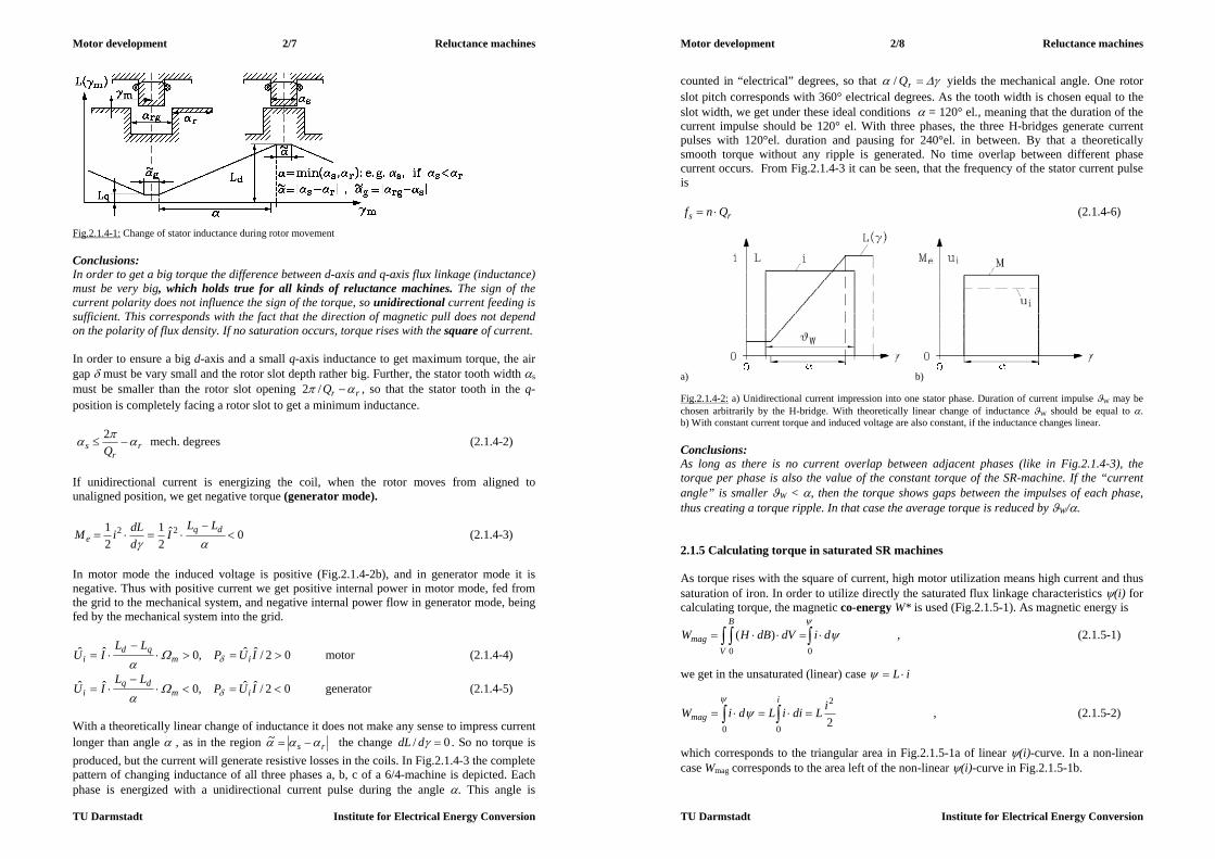
Motor development 2/7 Reluctance machines
TU Darmstadt Institute for Electrical Energy Conversion
Fig.2.1.4-1: Change of stator inductance during rotor movement Conclusions: In order to get a big torque the difference between d-axis and q-axis flux linkage (inductance) must be very big, which holds true for all kinds of reluctance machines. The sign of the current polarity does not influence the sign of the torque, so unidirectional current feeding is sufficient. This corresponds with the fact that the direction of magnetic pull does not depend on the polarity of flux density. If no saturation occurs, torque rises with the square of current. In order to ensure a big d-axis and a small q-axis inductance to get maximum torque, the air gap must be vary small and the rotor slot depth rather big. Further, the stator tooth width s
must be smaller than the rotor slot opening rrQ /2 , so that the stator tooth in the q-position is completely facing a rotor slot to get a minimum inductance.
rr
s Q
2 mech. degrees (2.1.4-2)
If unidirectional current is energizing the coil, when the rotor moves from aligned to unaligned position, we get negative torque (generator mode).
0ˆ21
21 22
dq
eLL
IddLiM (2.1.4-3)
In motor mode the induced voltage is positive (Fig.2.1.4-2b), and in generator mode it is negative. Thus with positive current we get positive internal power in motor mode, fed from the grid to the mechanical system, and negative internal power flow in generator mode, being fed by the mechanical system into the grid.
02/ˆˆ,0ˆˆ
IUPLL
IU imqd
i
motor (2.1.4-4)
02/ˆˆ,0ˆˆ
IUPLL
IU imdq
i
generator (2.1.4-5)
With a theoretically linear change of inductance it does not make any sense to impress current longer than angle , as in the region rs ~ the change 0/ ddL . So no torque is produced, but the current will generate resistive losses in the coils. In Fig.2.1.4-3 the complete pattern of changing inductance of all three phases a, b, c of a 6/4-machine is depicted. Each phase is energized with a unidirectional current pulse during the angle . This angle is
Motor development 2/8 Reluctance machines
TU Darmstadt Institute for Electrical Energy Conversion
counted in “electrical” degrees, so that rQ/ yields the mechanical angle. One rotor slot pitch corresponds with 360° electrical degrees. As the tooth width is chosen equal to the slot width, we get under these ideal conditions = 120° el., meaning that the duration of the current impulse should be 120° el. With three phases, the three H-bridges generate current pulses with 120°el. duration and pausing for 240°el. in between. By that a theoretically smooth torque without any ripple is generated. No time overlap between different phase current occurs. From Fig.2.1.4-3 it can be seen, that the frequency of the stator current pulse is
rs Qnf (2.1.4-6)
a) b) Fig.2.1.4-2: a) Unidirectional current impression into one stator phase. Duration of current impulse W may be chosen arbitrarily by the H-bridge. With theoretically linear change of inductance W should be equal to . b) With constant current torque and induced voltage are also constant, if the inductance changes linear. Conclusions: As long as there is no current overlap between adjacent phases (like in Fig.2.1.4-3), the torque per phase is also the value of the constant torque of the SR-machine. If the “current angle” is smaller W < , then the torque shows gaps between the impulses of each phase, thus creating a torque ripple. In that case the average torque is reduced by W/. 2.1.5 Calculating torque in saturated SR machines As torque rises with the square of current, high motor utilization means high current and thus saturation of iron. In order to utilize directly the saturated flux linkage characteristics (i) for calculating torque, the magnetic co-energy W* is used (Fig.2.1.5-1). As magnetic energy is
00
)( didVdBHWV
B
mag , (2.1.5-1)
we get in the unsaturated (linear) case iL
2
2
00
iLdiiLdiWi
mag
, (2.1.5-2)
which corresponds to the triangular area in Fig.2.1.5-1a of linear (i)-curve. In a non-linear case Wmag corresponds to the area left of the non-linear (i)-curve in Fig.2.1.5-1b.

Motor development 2/9 Reluctance machines
TU Darmstadt Institute for Electrical Energy Conversion
Fig.2.1.4-3: Three phase 6/4-SR machine: Unidirectional current impression is done for W = = 120° el. for each phase, yielding a theoretically smooth torque. A current impression of 180° at this ideal linear change of inductance will only increase resistive losses, but not torque. Magnetic co-energy is defined as
magWiW * (2.1.5-3) and corresponds to the area to the right of the (i)-curve in Fig. 2.1.5-1.
Motor development 2/10 Reluctance machines
TU Darmstadt Institute for Electrical Energy Conversion
When the rotor is turning, the magnetic flux linkage changes from one characteristic to the next (see Fig.2.1.2-2). Assuming linear characteristics in Fig.2.1.5-2 and operation with constant current i0, a movement of the rotor towards aligned position means a changing from a lower to an upper (i)-curve. We assume a (very small) rotor step d , then the change of magnetic energy and co-energy by moving from characteristic 1 to characteristic 2 yields an increase of magnetic energy and of co-energy, as the total flux linkage is now larger by the value d. By comparing the areas in Fig.2.1.5-2 (left), we note
*01,1,2, dWdiWdWWW magmagmagmag . (2.1.5-4)
a) b) Fig.2.1.5-1: Magnetic energy Wmag and co-energy W* for a) linear (unsaturated) and b) non-linear (saturated) flux linkage
Fig.2.1.5-2: A very small rotor movement leads to a small change from flux linkage 1 (left) to flux linkage 2 (right) From the voltage equation we get the energy balance during the very small step d, corresponding to the time step dt :
mmagoe dAdWdtiRdidtiRdtiudWdt
diRu 200
200 (2.1.5-5)
A very small time step leads to an increase of loss and magnetic energy. The delivered torque produces mechanical work :
dtMdMdA meem (2.1.5-6) By comparing (2.1.5-4) and (2.1.5-5), we see

Motor development 2/11 Reluctance machines
TU Darmstadt Institute for Electrical Energy Conversion
mmagmag dAdWdWdWdi *0 mdAdW * , (2.1.5-7)
thus getting the following torque equation
ddWiMe
*),( (2.1.5-8)
When changing from q- to d-position, the change in co-energy *W is the area between the d(i)-curve and the q(i)-curve. For maximizing the torque of a SR motor, this area has to be as big as possible, which demands a very high motor current. If the motor is unsaturated, the magnetic energy and co-energy are equal. This means that increase of co-energy gives the same increase to magnetic energy. As with each switch-on and switch-off of one phase the complete magnetic energy has to be put into the system and afterwards taken out, the feeding inverter must be rated for this additional amount of energy flow either by over-sizing voltage or current rating. In saturated machines, with increasing current the co-energy rises much stronger than magnetic energy (Fig.2.1.5-1b), which is very economical for inverter rating. Therefore SR machines should be operated as highly saturated machines, which is quite contrary to many other electric machines. Conclusions: Torque calculation can be done from the map of (i)-curves, evaluating the change of co-energy with change of rotor angle for a given current i. SR machines shall be operated highly saturated in order to limit inverter rating by limiting switched magnetic energy. In low current operation (no saturation) co-energy difference between d- and q-position equals a triangle area. Triangle surface is proportional to 2i . Thus torque rises with square of current. At high saturation increase of co-energy difference between d- and q-position increases linear with rising current. Therefore torque of saturated SR machines rises linear with current (Fig.2.1.5-3).
a) b) Fig.2.1.5-3: Torque-current characteristic: a) Torque is proportional to change of co-energy between d- and q-position W*, which in unsaturated case i < isat is proportional i2, in saturated case i > isat tends to be proportional nearly i , b) Torque-current characteristic with unsaturated and saturated part (IN: rated current) 2.1.6 SR machine operation at real conditions a) Real change of inductance between unaligned and aligned position: In Fig.2.1.6-1a the change of inductance - calculated with Finite Elements - is shown for the 8/6-motor of Fig.2.1.1-1b, being compared with the linear approximation of Section 2.1.2 and
Motor development 2/12 Reluctance machines
TU Darmstadt Institute for Electrical Energy Conversion
with measurement. Thus the angle of real change of inductance is larger than the angle . The derivative ddL / is not constant, but looks like a hump (Fig.2.1.6-1b). Thus even with
constant current the torque ddLiMe /)2/()( 2 is not any longer constant, but shows a considerable torque ripple. In the same way induced voltage is also now hump-like shaped:
mi ddLiu /)( .
a) b) Fig.2.1.6-1: Numerical calculation of inductance and torque for the 8/6-motor of Fig.2.1.1-1b, compared with measurement. Although current is constant, torque is not, showing a considerable ripple. This torque ripple may be reduced a little bit, if the current angle is increased: W > . Maximum possible angle is W =180°. Bigger angle would already generate braking torque. In Fig. 2.1.6-2a the torque ripple is shown for current angle 120°. By increasing angle to 180° (Fig. 2.1.6-2b), the torque contributions of adjacent phases overlap, resulting in a smoother total torque and a slight increase in average torque on the expense of higher resistive losses.
a) b) Fig.2.1.6-2: Torque ripple in SR machines: a) Due to non-linear change of inductance torque per tooth and phase shows a hump-like shape, thus reducing average torque and generating torque ripple b) If current angle is increased from 120° to 180°, torque ripple is reduced a little bit and average torque is raised.

Motor development 2/13 Reluctance machines
TU Darmstadt Institute for Electrical Energy Conversion
Conclusions: Real SR machines show considerable torque ripple already at low speed, when operated with constant current. Frequency of torque ripple is given by stator frequency rs Qnf per phase and number of phases m, thus mQnf rpuls . Average resistive losses per period T = 1/fs are calculated with
2
0
21 IRmdtiT
RmPT
Cu , (2.1.6-1)
where r.m.s-value of unipolar current is depending on current angle, which for 120° gives a ratio of time of current flow vs. period of x120 = 120°/360° = 1/3 and for 180° the value x180 = 1/2:
IxxTIT
dtIT
dtiT
IxTT
ˆˆ1ˆ11 2
0
2
0
2 (2.1.6-2)
Conclusions: For 180° current angle the resistive losses are 50% higher than with 120° current angle (x180/x120 = 3/2 = 1.5). b) Real shape of unidirectional current: In order to get block shaped unidirectional current, the H-bridge per phase is chopping the DC link voltage, and tries to keep by hysteresis current control the current amplitude within a certain small hysteresis band. The H-bridge of Fig.2.1.1-1a is chopping the DC link voltage Ud e.g. by switching upper transistor T2 on and off. Current flow continues – driven by stored magnetic energy Wmag - with T2 “off” by flowing through free-wheeling diode D1. Turning off current is accomplished by switching off T1 and T2. The current continues to flow via diodes D1 and D2 against the direction of DC link voltage and is therefore reduced rather quick. Stored magnetic energy is fed back to DC link. From voltage equation
0orUorUddLi
dtdiLiRu ddm
(2.1.6-3)
we see at low speed m, that induced voltage is much smaller than Ud, thus being neglected. If we also neglect resistance, current rises and decreases linear according to dtdiLu / (Fig.2.1.6-3, left). Thus the ideal block shaped unipolar current is more or less well reached by the chopping operation. At high speed the time duration TW ~ 1/n for current pulse is very short according to high current frequency. The time constant of phase winding RLTe / is now even larger than TW, so current rise is much longer than the wished time duration of current pulse. No longer chopping mode is possible. It is only possible to switch DC link voltage on and off. Therefore current pulse shape is no longer of block shape, but determined by the difference of constant DC link voltage and hump-like shaped induced voltage
)(iu (Fig.2.1.6-3, right). With this current shape )(i the torque ripple increases
drastically: ddLiMe /)2/)(()( 2 . In Fig.2.1.6-4 unidirectional current for very low (left) and very high (right) speed is shown. Please note, that rise and fall of current at low speed is determined mainly by inductance, which increases with time towards aligned
Motor development 2/14 Reluctance machines
TU Darmstadt Institute for Electrical Energy Conversion
position. Thus current rise and fall of current ripple in hysteresis band is slowed changes is slowed down with inductance increase.
Fig.2.1.6-3: Real current shape: Left: At low speed hysteresis control of current allows generating rather block shaped unidirectional current. Right: At high speed time is too short to chop DC link voltage, so only “voltage on” and “off” is possible, leading to distorted current pulse, which generates increased torque ripple
Fig.2.1.6-4: Real current shape: Left: At very low speed, Right: At very high speed time (with time scale extremely enlarged, compared to left figure) 2.1.7 SR Drive operation – torque-speed characteristic Maximum possible torque vs. speed is called torque-speed characteristic, which is consisting of mainly two sections: current limit and voltage limit.

Motor development 2/15 Reluctance machines
TU Darmstadt Institute for Electrical Energy Conversion
a) Voltage limit: At high speed the induced voltage (back EMF), which is increasing with increasing speed, limits current flow, as stator voltage cannot surpass maximum value DC link voltage Ud. The induced voltage and the resistive and inductive voltage drop equal the DC link voltage (“voltage limit”). Neglecting resistance R = 0 and assuming constant back EMF
ii Uu ˆ)( and constant current Ii ˆ)( , the condition for voltage limit is:
midid ddLIUUU
dtIdLIRUu
ˆˆˆˆˆ . (2.1.7-1)
Current flow at voltage limit is
mqd
d
ms
dLL
UddL
UI1
/)(1
/ˆ
. (2.1.7-2)
Possible current flow rises with inverse of decreasing speed, until it reaches the inverter current limit maxI at speed
/)(ˆ21
max qd
dg LLI
Un
. (2.1.7-3)
Thus torque-speed characteristic at voltage limit is therefore
2
/)(21
m
d
qde
ULL
M
, gnn (2.1.7-4)
Conclusions: At the voltage limit the maximum possible torque of SR drives decreases with the square of rising speed. b) Current limit:
a) b) Fig.2.1.7-1: Torque-speed characteristic of SR machine, a) for ideal block-shaped current, b) considering real current shape, which deviates from block shape with rising speed
Motor development 2/16 Reluctance machines
TU Darmstadt Institute for Electrical Energy Conversion
Inverter current limit is also thermal limit of inverter, as thermal time constant of semi-conductor devices is below 1 s. Motor thermal current limit (“rated current”) usually is 50% of this inverter current limit. So short time overload capability of machine is 100%, as its thermal time constant is - rising with motor size and depending on cooling system – about several minutes to typically half an hour. Maximum torque Mmax(Imax) of drive system is available in the base speed region gnn 0 (Fig.2.1.7-1a). In real SR machines with rising speed the current shape cannot be kept as ideal block. Therefore torque ripple increases with rising speed and average torque decreases. Hence real speed torque characteristics, mapping average torque versus speed, have maximum torque at low speed (Fig.2.1.7-1b). 2.1.8 Inverter rating a) Static rating: In each phase per switching instant the total electric energy must be put into the motor phase, not only the mechanic energy and loss energy, but also total magnetic energy. Each phase is only energized during “current angle” W. Neglecting losses, we consider total energy per switching as
*WWAWW magmmagtot (2.1.8-1) In Fig.2.1.5-3 a simplified flux linkage characteristic with Lq << Ld , assuming Lq = 0, and with constant saturated flux linkage satdd , , allows estimation of ratio
))2/((1
1)2/(
/max,,max
,max*iiii
iWW
WWWsatsatdsatsatd
satd
magtot
tottot
. (2.1.8-2)
Example 2.1.8-1:
2/max satii : 33.13/4/ * WWtot For static energy demand the inverter must be capable of 133% motor power rating to switch also the total amount of magnetic energy. With three phase motors, the three H-bridge inverters need a total amount of six IGBTs and six free-wheeling diodes like three phase inverters for rotating field AC machines like induction or synchronous machines. b) Dynamic rating: The electric winding time constant
Cu
mage P
WRLT ~ (2.1.8-3)
rules the current rise in simple coils. In SR machines also the back EMF must be considered, which rises with rising speed. Neglecting resistance at high speed, voltage equations yields
dm UddLi
dtdiLu
. (2.1.8-4)

Motor development 2/17 Reluctance machines
TU Darmstadt Institute for Electrical Energy Conversion
The solution of this 1st order differential linear equation is
UTt
m
d eddL
Ui /1/
, ddL
LTm
U / , (2.1.8-5)
which shows that for reaching sufficient current within time TU, a high DC link voltage is necessary. So dynamic condition demands considerable voltage and thus big inverter rating for getting rather block shaped current also at high speed. Conclusions: If inverter rating has to be limited because of costs, there is no sufficient surplus DC link voltage to impress block shaped unidirectional current also at high speed. Therefore current deviates from ideal block shape at high speed, causing increased torque ripple and decreased average torque, thus reducing motor power output. c) Inverter current control: (i) At low speed: Block current by hysteresis control with constant current angle W , usually 180° or 120° (increased torque ripple, decreased resistive losses). Current rise and fall time tr and tf very short in relation to current impulse duration TW. (ii) Increased speed: Current impulse duration TW decreases with increased speed, tr and tf are now significant parts of current flow duration, so current impulse gets trapezoidal shape, and average torque decreases. (iii) At high speed: The current impulse duration TW is too short for chopping with hysteresis control. So only voltage “switch on – switch off” mode is possible. Current angle, determined by switch on and switch-off angle, adjusted to speed, so that average torque decreases with 1/n (constant power operation). (iv) Voltage limit: No adjusting of current angle possible, because of too short time TW; average torque decreases with 1/n2 .
Fig.2.1.8-1: Maximum torque & power, depending on speed with inverter control according to sections (i) ... (iv), see text.
Motor development 2/18 Reluctance machines
TU Darmstadt Institute for Electrical Energy Conversion
2.1.9 Motor technology and performance a) Advantages: - simple, low cost motor construction - no distributed AC winding; simple tooth-wound coils; no overlap in winding overhangs - smaller number of slots than in comparable AC machines, simple manufacturing - robust rotor without any winding or magnets, thus well suited for high speed - low rotor inertia - Independent feeding of phases: if one phase fails, motor with m 3 is still capable of self
starting and running at reduced torque without overloading the “healthy” windings - Compared with inverter fed induction machines, SR machine has increased efficiency due
to lower rotor losses (Example 2.1.9-1). b) Disadvantages: - High torque ripple with increased speed. At very low speed current profiling by inverter
current control is possible to cancel torque ripple, but not at elevated speed due to limited inverter rating.
- Increased number of phases will reduce torque ripple, but number of semiconductor switches rises (expensive !)
- No standard three phase AC inverter applicable; special H-bridge inverter is necessary. - Danger of exciting torsion resonance vibrations by torque ripple at variable speed
operation - Magnetically excited acoustic noise: Pulsating radial magnetic pull with frequency
mQnf rpuls causes radial vibrations of stator yoke and housing, which compresses / decompresses air with same frequency, causing acoustic sound. Acoustic sound is especially big, if frequency pulsf coincides with eigen-frequency of stator yoke and housing (resonance). As flux per pole is only flux per teeth, thus rather small, stator yoke is very thin and “rings like a bell” (Fig.2.1.9-1).
- Strong decrease of maximum torque with rising speed due to increased torque ripple. - Increased inverter rating due to switching on/off of magnetic energy at each phase
switching. - Usually rotor position sensor needed for optimum inverter-motor operation
Fig.2.1.9-1: Measured sound pressure level of 7.5 kW 12/8 SR machine (Fig.2.1.1-2) in anechoic chamber (1: rated current, 2: no-load current). At no-load torque and current is very small, so air gap flux density B ~ i and exciting radial magnetic pull fr ~ B
2 ~ i2 is small, leading to low magnetic noise. At rated load noise is rather big, showing sharp maximum when exciting frequency coincides with stator resonance frequencies.

Motor development 2/19 Reluctance machines
TU Darmstadt Institute for Electrical Energy Conversion
c) Electromagnetic motor utilization: Torque per motor active volume may be compared with standard induction machines. For the same cooling system about 80% of utilization of induction machine is reached. In spite of small flux per pole (tooth flux = pole flux) this can be achieved by - high slot fill factor due to tooth-wound coils, - short winding overhangs due to tooth-wound coils, thus decreasing resistive losses - reduced iron losses in rotor especially at low speed. Example 2.1.9-1: Comparison of inverter fed induction and SR motor (see Fig.2.1.1-2) for the same rated power and speed at identical cooling (totally enclosed, fan mounted on shaft): Data: 7.5 kW, shaft height 132 mm, base speed 1500/min, top speed 3000/min, Thermal Class F, three-phase four-pole machines
Motor data Switched Reluctance Machine
Induction Machine SRD/IM Ratio
Outer/inner stator diameter dsa/dsi (mm) 210 / 120.9 200 / 122.6 +5% /-1% Outer rotor diameter/ air gap dra/ (mm) 120 / 0.45 122 / 0.3 -1%/+50%
Tooth number: Stator/ Rotor Qs/Qr 12 / 8 unskewed 48 / 36 skewed Yoke height stator/rotor hys/hyr (mm) 14 / 17.5 21.5 / 16 Tooth width stator/ rotor bts/btr (mm) 16 / 16.7 4.3 / 6
Stack length lFe (mm) 193 135 +42% Stack length + end winding overhangs (mm) 193 + 2x18 = 229 135 + 2x47 = 229 0% Stator resistance per phase (20 °C) Rs (Ohm) 0.85 0.512 Y +64%
Armature winding / slot space factor One coil per stator tooth / 0.44
Single-layer, full-pitched / 0.38
--/+16%
Number of turns per phase Ns 244 112 +118% Stator frequency fs for n = 0..3000/min 0 ... 400 Hz 0 ... 100 Hz +300%
Cylindrical rotor volume dra2lFe/4 2.18 dm3 1.58 dm3 + 38%
Rotor moment of inertia (measured) 0.0195 kgm2 0.024 kgm2 -19% Table 2.1.9-1: Some basic design data for the Switched Reluctance Machine and the Induction Machine. Comparison of measured loss balance at rated speed:
Switched Reluctance Machine Induction Machine Input / Output power Pin / Pout 9440 W/ 8480 W 9950 W/ 8480 W
Phase current I/ I 13.3 A/ 27.5 A 17.45 A/ 30 A Stator frequency fs 200 Hz 52 Hz (Us,k=1 = 225.5V)
Armature temperature rise 110 K 101 K Iron losses / friction & windage losses 200 W/ 165 W 265 W/ 55 W
Stator copper losses/cage losses 595 W/ 0 W 650 W/ 350 W Additional losses 0 W 150 W
Stator current density Js 5.25 A/mm2 8.23 A/mm2 Current loading A = 2mNsIs/(dsi) 513 A/cm 305 A/cm
Motor efficiency mot 89.8 % 85.2 % Inverter efficiency inv 96.6 % 97.0%
Drive efficiency 86.7 % 82.6 % Table 2.1.9-2: Measured results of thermal load run for 1500/min, 54 Nm and Ud = 540 V. Cooling was performed with a shaft-mounted fan of 230mm outer diameter and 7 radial fan blades. Conclusions: Short winding overhangs allow increased iron stack length, so for the same outer motor dimensions inverter fed induction machine and SR machine have nearly the same power output at same motor size. At low speed due to lower motor losses SR torque may be
Motor development 2/20 Reluctance machines
TU Darmstadt Institute for Electrical Energy Conversion
increased (high starting torque). SR motor shows increased efficiency when compared with induction machine due to lack of cage losses.
Fig.2.1.9-2: Comparison of measured motor efficiency of 7.5 kW, four-pole 12/8 SR machine (SRD) and inverter-fed standard induction machine (IM) at 54 Nm, 100 K armature temperature rise for different motor speed. Inverter efficiency of about 97% has to be added in both cases. 2.1.10 Applications of SR drives Standard variable speed SR drives have been designed and manufactured to compete with inverter-fed variable speed induction machines. More importance was gained by using the SR drive in special applications, where variable speed drives for - cheap mass production (e.g. drive in electric cars, pump and compressor drives), - special purpose in rough environment (e.g. mills in coal mines, explosion hazard utilities
such as oil fields) - robust high speed drives (e.g. starter-generator for air craft engine) are needed. For some of these cases the magnetic noise of motor is not of interest, as the driven load is already noisy (e.g. air craft engine). Example 2.1.10-1: Starter-generator for military aircraft jet (US Air Force, manufacturer GE) - Rated power: 250 kW, rated speed 13 500/min, rated torque 177 Nm, rated current 750 A,
DC link voltage 270 V - Maximum speed 22200/min, overspeed 26000/min, overall system efficiency: 90% - Three phase four pole 12/8 SR machine, For reliability two independent three phase systems are arranged with each 125 kW power. In case of failure motor is “fail-silent” = no current = no force = no induced voltage, so risk of fire due to short circuit is minimized. In order to decrease motor size and mass, motor is intensively cooled by oil. So motor mass is only 70 kg, yielding “power weight” of P/m = 3.6 kW/kg. In low speed region 0 ... 13500/min SR machine is used to start compressor of air craft engine with constant torque 177 Nm.

Motor development 2/21 Reluctance machines
TU Darmstadt Institute for Electrical Energy Conversion
In high speed region 13500 ... 26000/min SR machine is driven by air craft engine as generator with constant power output 250 kW (Fig.2.1.10-1).
a)
b)
Fig.2.1.10-1: 250 kW four-pole SR machine as starter-generator for aircraft; a) Torque-speed characteristic, b) Measured and calculated torque-current-curve (above 400 A the SR machine is saturated). 2.2 Synchronous reluctance machines 2.2.1 Basic function of synchronous reluctance machine The stator of the synchronous reluctance machine is slotted, with a distributed AC winding like a PM synchronous machine. So stator winding is usually fed from sinus three-phase voltage system; current in winding is also three-phase sinus system. The rotor is consisting of deep slots between the poles in the q-axis (“inter-pole gaps”), whereas with the d-axis the air gap is as small as possible. Fig.2.2.1-1a shows a typical 4 pole rotor with slot width of 36° and pole width 54°, with resulting pole pitch 90°. In the pole region slots containing squirrel cage segments for asynchronous starting at fixed stator voltage (“line start”) are arranged. After asynchronous starting, when the rotor has accelerated up to synchronous speed of stator rotating magnet field, this stator field exerts tangential magnetic pull on the rotor, if the rotor poles are not in d- or q-position (Fig.2.2.1-2). In d- and q-position total tangential magnetic
Motor development 2/22 Reluctance machines
TU Darmstadt Institute for Electrical Energy Conversion
pull on rotor is zero, so no torque is generated. In positions between d- and q-position asymmetric flow of flux across rotor and air gap generates resulting tangential pull and therefore synchronous reluctance torque. This torque tries to align rotor in d-position against load torque, thus generating mechanical power output (motor mode).
Fig.2.2.1-1: Different shapes (at different scale) of rotor cross section of 4-pole, 3-phase synchronous reluctance machines (Steady state power at Thermal Class F, totally enclosed, shaft-mounted fan, 50 Hz, synchronous speed 1500/min). Rotor a) 2.2 kW, shaft height 112 mm, rotor b) 550 W, shaft height 80 mm (Siemens AG, Germany).
a) b) c) Fig.2.2.1-2: Numerically calculated flux lines per pole for rated current for motor a) of Fig.2.2.1-1: Rotor is a) in q-position (current angle = 90°), b) half between q- and d-position, = 45°, c) in d-position, = 0° If rotor is driven mechanically, and rotor is leading ahead d-position of stator field, polarity of torque is reversed, thus operating as generator with power flow from shaft to grid. But always magnetizing current from grid is needed to excite air gap flux, so always current will be lagging behind voltage. Conclusions: Synchronous reluctance machine is fed by three-phase sinus voltage system, and may be operated as motor or generator. Due to magnetizing current the stator current is always lagging (inductive current). No position sensor is needed, but load angle between rotor axis and stator field (Fig.2.2.2-1) increases with increased torque demand up to maximum torque at 45° load angle. This maximum torque is static pull-out torque Mp0. By surpassing this angle and torque, the rotor

Motor development 2/23 Reluctance machines
TU Darmstadt Institute for Electrical Energy Conversion
is pulled out of synchronism and runs asynchronously with the starting cage segments being induced and producing asynchronous torque. Rotor is very robust and cheap, as it contains neither winding and magnets nor position sensor. Rotor speed in synchronism is exactly synchronous speed according to Section 1.1.1
pfn ssyn / (2.2.1-1) Example 2.2.1-1: Pole count - 2 4 6 8
Speed 1/min at 50 Hz 3000 1500 1000 750 Speed 1/min at 60 Hz 3600 1800 1200 900
2.2.2 Voltage and torque equation of synchronous reluctance machine Comparing synchronous reluctance machine with PM synchronous machine of section 1, we see that back EMF Up is zero, as no rotor excitation exists. On the other hand stator main inductance Lh for d-axis with small air gap is much bigger than for q-axis with big air gap of rotor inter-pole gap: hqhd LL . When each phase of stator winding is fed by stator voltage Us, the stator current Is will be lagging by phase angle . By decomposing stator current in two components with 90° phase shift, we get d-component of current Id, magnetizing the rotor along d-axis, and q-component of current Iq, magnetizing current along q-axis. Air gap field of d-component experiences small air gap and therefore self-induced voltage dhds IL of that stator field component is big according to self-inductance Lhd, whereas in q-axis only smaller Lhq will result in smaller self-induced voltage qhqs IL . Thus total voltage per phase is given by these two components of self-induced voltage of air gap field and of self-induced voltage due to stator stray flux in slots and winding overhangs and resistive voltage drop. As voltages and currents are sinusoidal, complex phasor calculation may be used. The real axis of complex co-ordinate system is chosen to coincide with rotor d-axis, and imaginary axis with rotor q-axis.
qdqds IIjIII (2.2.2-1) Voltage equation:
hsssssqhqsdhdsssssss UILjIRILjILjILjIRU (2.2.2-2) With defining synchronous d- and q-axis inductance
hqsqhdsd LLLLLL , (2.2.2-3) and synchronous d- and q-axis reactance qsqdsd LXLX , and neglecting resistive losses, voltage equation is
qqddqqdds IXIjXIjXIjXU . (2.2.2-4)
Motor development 2/24 Reluctance machines
TU Darmstadt Institute for Electrical Energy Conversion
In Fig.2.2.2-1 for a two-pole synchronous reluctance machine this voltage equation is depicted as complex phasor diagram, showing a) lagging stator current with phase angle , b) decomposition of current in d- and q-component, c) current angle between direction of current phasor and d-axis, d) load angle between stator voltage phasor and q-axis e) motor operation, as cos is positive ( 2/ ) .
Fig.2.2.2-1: Phasor diagram for synchronous reluctance machine for motor operation. Flux linkage phasors may be taken as direction of air gap flux components. In addition, the values of air gap flux linkages
2 dhdhd IL , 2 qhqhq IL (2.2.2-5) indicate, that resulting air gap flux
hqhdh (2.2.2-6) has its direction much closer to d-axis than current phasor. Note, that if Lhd = Lhq, then direction of resulting flux would be the direction of current phasor, so reluctance rotor directs flux into d-axis direction, thus generating reluctance torque. Electrical real Pe is converted in motor mode into mechanical power. Neglecting losses, voltage equation (2.2.2-4) yields
emqddqdqsssssse MIIXIIXmIUIUmIUmP Im,Im,Re,Re,cos
qdqds
e IIXXmpM
(2.2.2-7)
Conclusions: A big difference between d- and q-axis inductance is needed to generate sufficient torque (typically Ld/Lq ~ 5). Current component Id may be taken as magnetizing current, exciting the
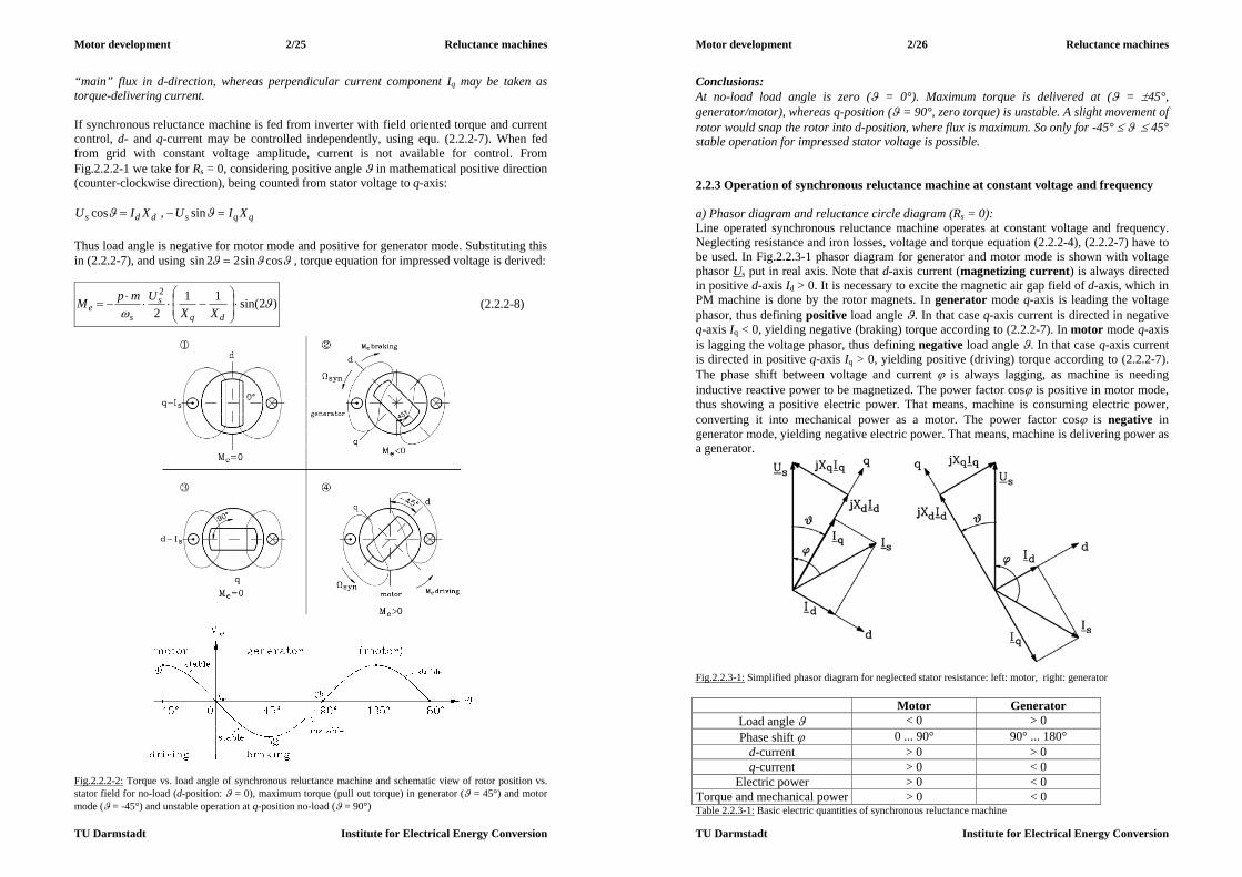
Motor development 2/25 Reluctance machines
TU Darmstadt Institute for Electrical Energy Conversion
“main” flux in d-direction, whereas perpendicular current component Iq may be taken as torque-delivering current. If synchronous reluctance machine is fed from inverter with field oriented torque and current control, d- and q-current may be controlled independently, using equ. (2.2.2-7). When fed from grid with constant voltage amplitude, current is not available for control. From Fig.2.2.2-1 we take for Rs = 0, considering positive angle in mathematical positive direction (counter-clockwise direction), being counted from stator voltage to q-axis:
qqsdds XIUXIU sin,cos Thus load angle is negative for motor mode and positive for generator mode. Substituting this in (2.2.2-7), and using cossin22sin , torque equation for impressed voltage is derived:
)2sin(112
2
dq
s
se XX
UmpM (2.2.2-8)
Fig.2.2.2-2: Torque vs. load angle of synchronous reluctance machine and schematic view of rotor position vs. stator field for no-load (d-position: = 0), maximum torque (pull out torque) in generator ( = 45°) and motor mode ( = -45°) and unstable operation at q-position no-load ( = 90°)
Motor development 2/26 Reluctance machines
TU Darmstadt Institute for Electrical Energy Conversion
Conclusions: At no-load load angle is zero ( = 0°). Maximum torque is delivered at ( = 45°, generator/motor), whereas q-position ( = 90°, zero torque) is unstable. A slight movement of rotor would snap the rotor into d-position, where flux is maximum. So only for -45° 45° stable operation for impressed stator voltage is possible. 2.2.3 Operation of synchronous reluctance machine at constant voltage and frequency a) Phasor diagram and reluctance circle diagram (Rs = 0): Line operated synchronous reluctance machine operates at constant voltage and frequency. Neglecting resistance and iron losses, voltage and torque equation (2.2.2-4), (2.2.2-7) have to be used. In Fig.2.2.3-1 phasor diagram for generator and motor mode is shown with voltage phasor Us put in real axis. Note that d-axis current (magnetizing current) is always directed in positive d-axis Id > 0. It is necessary to excite the magnetic air gap field of d-axis, which in PM machine is done by the rotor magnets. In generator mode q-axis is leading the voltage phasor, thus defining positive load angle . In that case q-axis current is directed in negative q-axis Iq < 0, yielding negative (braking) torque according to (2.2.2-7). In motor mode q-axis is lagging the voltage phasor, thus defining negative load angle . In that case q-axis current is directed in positive q-axis Iq > 0, yielding positive (driving) torque according to (2.2.2-7). The phase shift between voltage and current is always lagging, as machine is needing inductive reactive power to be magnetized. The power factor cos is positive in motor mode, thus showing a positive electric power. That means, machine is consuming electric power, converting it into mechanical power as a motor. The power factor cos is negative in generator mode, yielding negative electric power. That means, machine is delivering power as a generator.
Fig.2.2.3-1: Simplified phasor diagram for neglected stator resistance: left: motor, right: generator
Motor Generator Load angle < 0 > 0 Phase shift 0 ... 90° 90° ... 180°
d-current > 0 > 0 q-current > 0 < 0
Electric power > 0 < 0 Torque and mechanical power > 0 < 0 Table 2.2.3-1: Basic electric quantities of synchronous reluctance machine
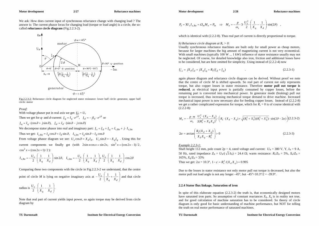
Motor development 2/27 Reluctance machines
TU Darmstadt Institute for Electrical Energy Conversion
We ask: How does current input of synchronous reluctance change with changing load ? The answer is: The current phasor locus for changing load (torque or load angle) is a circle, the so-called reluctance circle diagram (Fig.2.2.3-2).
Fig.2.2.3-2: Reluctance circle diagram for neglected stator resistance: lower half circle: generator, upper half circle: motor Proof: With voltage phasor put in real axis we get: Us = Us Then we get for q- and d-current: j
ddj
qq ejIIeII , or
)cos(sin),sin(cos jIIjII ddqq
We decompose stator phasor into real and imaginary part: Im,Re, ssqds IjIIII
Thus we get: cossin,sincos Im,Re, dqsdqs IIIIII From voltage phasor diagram we see: qqsdds IXUIXU sin,cos . Using this for
current components we finally get (with 2/)12(cossin,2sincossin2 2 xxxxx ,
2/)12(coscos2 xx ):
2cos112
112
,2sin112 Im,Re,
dq
s
dq
ss
dq
ss XX
UXX
UIXX
UI
Comparing these two components with the circle in Fig.2.2.3-2 we understand, that the centre
point of circle M is lying on negative imaginary axis at
dq
sXX
U 112
and that circle
radius is
dq
sXX
U 112
.
Note that real part of current yields input power, so again torque may be derived from circle diagram by
Motor development 2/28 Reluctance machines
TU Darmstadt Institute for Electrical Energy Conversion
)2sin(112
332
Re,
dq
s
sememsse XX
UpMPMIUP ,
which is identical with (2.2.2-8). Thus real part of current is directly proportional to torque. b) Reluctance circle diagram at Rs > 0: Usually synchronous reluctance machines are built only for small power as cheap motors, because for larger machines the big amount of magnetizing current is not very economical. With small machines (typically 100 W ... 1 kW) influence of stator resistance usually may not be neglected. Of course, for detailed knowledge also iron, friction and additional losses have to be considered, but are here omitted for simplicity. Using instead of (2.2.2-4) now
)( qdsqqdds IIRIjXIjXU . (2.2.3-1) again phasor diagram and reluctance circle diagram can be derived. Without proof we note that the centre of circle M is shifted upwards. So real part of current not only represents torque, but also copper losses in stator resistance. Therefore motor pull out torque is reduced, as electrical input power is partially consumed by copper losses, before the remaining part is converted into mechanical power. In generator mode (braking) pull out torque is increased, thus increasing mechanical torque demand to drive machine. Increased mechanical input power is now necessary also for feeding copper losses. Instead of (2.2.2-8) we get a rather complicated expression for torque, which for Rs = 0 is of course identical with (2.2.2-8):
)22sin())(()(
)(2
)( 222222
2
qsdsqds
qds
qds
se XRXRXXR
XXR
XXUmpM (2.2.3-2)
0)(
arctan2 2
sqd
qds
RXX
XXR (2.2.3-3)
Example 2.2.3-1: Shaft height 112 mm, pole count 2p = 4, rated voltage and current: UN = 380 V, Y, IN = 9 A, 50 Hz, rated impedance ZN = UN/( 3 IN) = 24.4 ; warm resistance: Rs/ZN = 5%, Xd/ZN = 165%, Xq/ZN = 33% Thus we get: 2 = 10.3°, 995.0)/(1 2 qds XXR Due to the losses in stator resistance not only motor pull out torque is decreased, but also the motor pull out load angle is not any longer –45°, but –45°+10.3°/2 = -39.9°. 2.2.4 Stator flux linkage, Saturation of iron In spite of this elaborate equation (2.2.3-2) the truth is, that economically designed motors have saturated iron parts. So assumption of constant reactances Xd, Xq is in reality not true, and for good calculation of machine saturation has to be considered. So theory of circle diagram is only good for basic understanding of machine performance, but NOT for telling the truth on real motor performance of saturated machines.

Motor development 2/29 Reluctance machines
TU Darmstadt Institute for Electrical Energy Conversion
a)
b) Fig.2.2.3-3: Synchronous reluctance motor, considering stator resistance: a) torque, b) reluctance circle diagram a) NO saturation considered: If no saturation is considered, d- and q-inductivities differ mainly due to different air gaps in pole region and gap region (Fig. 2.2.4-1). So, if we consider always constant current Is in stator winding, but with changing angle with respect to d-axis, the flux linkage components are
sin2/,cos2/ sqqqqsdddd ILILILIL (2.2.4-1) Thus the locus of flux linkage s (and thus amplitude of fundamental of air gap flux density B) for varying current phasor Is on a circle is an ellipse.
122
22
sq
q
sd
dILIL
(2.2.4-2)
Motor development 2/30 Reluctance machines
TU Darmstadt Institute for Electrical Energy Conversion
Fig.2.2.4-1: Locus of flux linkage for constant, but phase shifted stator current for unsaturated iron is an ellipse b) WITH iron saturation considered:
a) b) Fig.2.2.4-2: Comparison of d-and q-axis flux linkage: a) Unsaturated iron: Different inclination of flux linkage increase is defined by different (small and large) air gap in d- and q-axis, b) Iron saturation causes non-linear increase of d-axis flux linkage. As q-axis flux linkage is much smaller, iron flux density is so low, that no saturation occurs within range of rated current. Calculating saturated flux linkage for different phase shifts and given current amplitude is done usually numerically, as shown in Fig.2.2.1-2. Stator winding is loaded in the three phases with current in that way, that for phase shift = 0° the excited air gap flux lines are directed in d-axis, and for = 90° they are in q-axis (across the pole gap). For other angles the direction of flux lines is in between. For each of these chosen angles the air gap flux density distribution B(x) is calculated for given current. By Fourier analysis the fundamental amplitude B1 is derived. With pole pitch, stack length, number of turns per phase of stator winding and winding factor of fundamental harmonic we get air gap flux linkage
112
BlkN Fepwsh . (2.2.4-3)
Varying the current Is, we get characteristics like those in Fig.2.2.4-3 (taken for the geometry of the motor of Fig.2.2.1-1a). So for each point of operation of reluctance machine (Fig.2.2.2-1) a certain current amplitude and angle is given. Then taking the value of the flux linkage from the map of characteristics Fig.2.2.4-3 (with interpolation for angles in between the numerically calculated ones) the induced voltage is calculated, thus completing the phasor diagram. Please note, the it is NOT sufficient to take only the flux linkage characteristic for d- and q-axis by decomposing the current according sin,cos sqsd IIII . If one would take these two current components, calculating with them the corresponding d- and q-flux
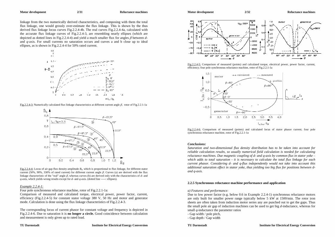
Motor development 2/31 Reluctance machines
TU Darmstadt Institute for Electrical Energy Conversion
linkage from the two numerically derived characteristics, and composing with them the total flux linkage, one would grossly over-estimate the flux linkage. This is shown by the thus derived flux linkage locus curves Fig.2.2.4-4b. The real curves Fig.2.2.4-4a, calculated with the accurate flux linkage curves of Fig.2.2.4-3, are resembling nearly ellipses (which are depicted as dotted lines in Fig.2.2.4-4) and yield a much smaller flux for angles between d- and q-axis. For small currents no saturation occurs and curves a and b close up to ideal ellipses, as is shown in Fig.2.2.4-4 for 50% rated current.
Fig.2.2.4-3: Numerically calculated flux linkage characteristics at different current angle , rotor of Fig.2.2.1-1a
Fig.2.2.4-4: Locus of air gap flux density amplitude B, which is proportional to flux linkage, for different stator current (50%, 90%, 330% of rated current) for different current angle . Curves (a) are derived with the flux linkage characteristic of the "real" angle , whereas curves (b) are derived only with the characteristics of d- and q-axis, which yields wrong results except for d- and q-axis. (dotted line -----: ellipses). Example 2.2.4-1: Four pole synchronous reluctance machine, rotor of Fig.2.2.1-1a: Comparison of measured and calculated torque, electrical power, power factor, current, efficiency (Fig.2.2.4-5) for constant stator voltage 380 V, 50 Hz and motor and generator mode. Calculation is done using the flux linkage characteristics of Fig.2.2.4-3. The corresponding locus of current phasor for constant voltage and frequency is depicted in Fig.2.2.4-6. Due to saturation it is no longer a circle. Good coincidence between calculation and measurement is only given up to rated load.
Motor development 2/32 Reluctance machines
TU Darmstadt Institute for Electrical Energy Conversion
Fig.2.2.4-5: Comparison of measured (points) and calculated torque, electrical power, power factor, current, efficiency; four pole synchronous reluctance machine, rotor of Fig.2.2.1-1a
Fig.2.2.4-6: Comparison of measured (points) and calculated locus of stator phasor current; four pole synchronous reluctance machine, rotor of Fig.2.2.1-1a Conclusions: Saturation and two-dimensional flux density distribution has to be taken into account for reliable calculation results, so usually numerical field calculation is needed for calculating reluctance machines. Due magnetic coupling of d- and q-axis by common flux in stator yoke – which adds to total saturation - it is necessary to calculate the total flux linkage for each current phasor. Considering d- and q-flux independently would not take into account this additional saturation effect in stator yoke, thus yielding too big flux for positions between d- and q-axis. 2.2.5 Synchronous reluctance machine performance and application a) Features and performance: Due to low power factor (e.g. below 0.6 in Example 2.2.4-1) synchronous reluctance motors are only built for smaller power range typically below 5 kW at 1500/min. The rotor iron sheets are often taken from induction motor series any are punched out to get the gaps. Thus the small pole air gap of induction machines can be used to get big d-inductance, whereas for small q-inductance the parameter ratios - Gap width / pole pitch, - Gap depth / Gap width

Motor development 2/33 Reluctance machines
TU Darmstadt Institute for Electrical Energy Conversion
have to be optimized to get a big ratio Xd/Xq. This is done often empirically for small motors. Pull out torque must be at least 1.35-faches MN to satisfy international standard IEC 60034-1. The rotor slots of the motor are used to form a cage for asynchronous line-starting of the machine. Often the rotor gaps are filled with aluminium for die-cast aluminium cage reluctance rotors to increase asynchronous starting torque at slip s = 1. Being operated from the grid with impressed stator voltage system, rotor may start speed slow oscillations at load steps like any synchronous machine, which is operated with independent voltage system. Rotor cage in that case acts as a damper (amortisseur winding), where currents are induced during these oscillations, causing an additional braking torque, which damps the oscillations rather quickly. Good synchronizing must be achieved by big ratio Xd/Xq to ensure, that after asynchronous starting the rotor is pulled from slip s > 0 into synchronism s = 0 also, when the motor is already loaded. The product of rated efficiency and power factor cos is shown in Fig.2.2.5-1 in comparison with line-operated induction motors and is lower du to the increased demand of magnetizing current, caused by the larger air gap of the pole gaps.
Fig.2.2.5-1: Product of measured rated efficiency and power factor for different motors: Comparison of 4-pole synchronous reluctance machine with line-operated induction motors Example 2.2.5-1: Comparison of 4-pole induction and synchronous reluctance machine, identical stator (shaft height 112 mm, 36 stator slots), totally enclosed, fan cooled (TEFC), 380 V Y, 9 A, 50 Hz
Induction motor Reluctance motor Output power 4 kW 2.2 kW Power factor 0.83 0.46 Efficiency 84 % 78 %
Rotational speed 1447 /min 1500 /min Table 2.2.5-1: Comparison of 4-pole induction and synchronous reluctance machine with identical stator Conclusions: Steady state torque per volume for a certain temperature rise of stator winding is by 30% to 50% lower for synchronous reluctance machines, when compared with induction machines.
Motor development 2/34 Reluctance machines
TU Darmstadt Institute for Electrical Energy Conversion
b) Inverter operation: Usually synchronous reluctance machines are operated with inverter without any speed control due to synchronous capability of motor. Thus again rotor oscillations may happen, which have to be damped by rotor cage. With changing speed and frequency it may happen, that at certain speed the cage damping is much weaker than at other speed levels. So some rules were found to ensure stable non-oscillating operation for a wide speed range: - reduction of ratio Xd/Xq (which of course is decreasing motor utilization), - aim a ratio of rotor cage resistance in d- and q-axis of about Rrd/Rrq = 0.5, - reduce rotor cage d-axis resistance Rrd, - increase stator and rotor d-axis stray inductance drs LL , - decrease stator resistance and rotor q-axis stray inductance qrs LR , Often these oscillations occur for machines with rated frequency 50 Hz at lower stator frequencies below 30 Hz. By increasing the ratio of ~/ ss fU , which means increase of flux and thus saturation, the d-axis reactance is saturated and therefore the ratio Xd/Xq is reduced, as mentioned above. Usually the oscillations vanish. c) Applications: Synchronous reluctance machines are special drives, which are used often in textile industry, where e.g. acryl threads for synthetic textiles are manufactured. Many threads are taken from one big lump of molten acryl mass and are cooled and wound up synchronously by synchronous machines. Often more than 100 machines are working in parallel. So often cheap synchronous reluctance machines are used, fed from one main inverter at variable speed. The synchronous reluctance machine is a "fail-silent" machine. In case of failure it can be switched off without further harming the system, in contrary to PM synchronous machines, where switched off, but still turning machines induce back EMF, causing losses. Conclusions: The synchronous reluctance machine is a special cheap, low power machine for special purposes, where synchronous speed is necessary. 2.2.6 Asynchronous starting of reluctance machines a) Asynchronous starting torque: Due to the rotor gaps the asynchronous starting torque is not constant for a certain slip. The stator air gap flux is rotating faster with the speed difference
pfsnsnsnnnn ssynsynsynsyn /)1( . (2.2.6-1) Therefore the asynchronous torque is changing twice its value, when the stator wave passes on rotor pole pair, as two rotor gaps are passed, where the flux and thus the torque are decreased. So asynchronous torque during start up has an average value and a component, pulsating with double slip frequency sfs 2 . b) Asynchronous reluctance torque: We assume for simplicity that the inverse air gap is varying along rotor co-ordinate xr sinusoidal:

Motor development 2/35 Reluctance machines
TU Darmstadt Institute for Electrical Energy Conversion
p
r
r
xx
2cos11)(
1
10 10 (2.2.6-2)
yielding air gap in d-axis10
10
d and in q-axis10
10
q . This "air gap distribution"
is moving synchronously with rotor speed n, thus with respect to stator co-ordinate xs we note
tfsxtnpxtvxx psrprrs 2)1(2 . (2.2.6-3) The stator air gap flux density wave, excited by sinusoidal distributed stator ampere turns
with amplitude swss IkNp
mV 21
txVtxV s
p
ssss
cos),( , (2.2.6-4)
is modulated by air gap. With abbreviation psx / we get
))1(22cos(11)cos(),(/),(),(
1000 tstVttVtB ssss
. (2.2.6-5)
By using 2/))cos()(cos(coscos , three field components are distinguished by modulation: - the stator fundamental with average air gap: )cos()/( 001, tVB sss - a field of same pole number, but different frequency: ))21(cos()2/( 103, tsVB sss - a field of 3-times pole number and different frequency: ))23(3cos()2/( 10 tsV ss . The three-fold pole pair field induces in the three phase windings voltage, which are IN phase. So, in three phase star connected stator winding systems with insulated star point, no currents can be driven by these voltages. Hence the influence of this wave is neglected. The second field induces in the stator windings a voltage system U3 with frequency
sfsf )21(3 , which causes an additional (small) stator current I3. The corresponding
sinusoidal distributed current ampere turns 313 2IkNp
mV ws
excite an additional air gap
field ...))21(cos()cos(),(/),(),( 2,31,3303 tsBtBttVtB ss , which again contains – with the same calculation as above - a field with three-fold pole pair (neglected here) and two field components 2,31,3 , BB . The two waves 1,31, , BBs have the same wave length and frequency, thus the same velocity, so they produce a constant torque 31,31,1 ~~ IIBBM ss . The same holds true for 2,sB ,
2,3B , again resulting in a constant torque 32,32,2 ~~ IIBBM ss . Therefore the constant part of asynchronous reluctance torque is formed by the sum of these to components:
321 ~ IIMMM sa . (2.2.6-6)
Motor development 2/36 Reluctance machines
TU Darmstadt Institute for Electrical Energy Conversion
On the other hand, the two waves 2,31, , BBs have the same wave length, but not the same frequency and velocity, so they produce a pulsating torque 32,31,1 ~~ IIBBM ssP . Difference of frequencies is sss fsfsf 2)21( , so frequency of pulsating torque is again double slip frequency. The same holds true for 1,32, , BBs , again resulting in a pulsating torque
31,32,2 ~~ IIBBM ssP , and also for 23,1,3 ~~ sssP IBBM , 2
32,31,34 ~~ IBBM P , all pulsating with double slip frequency. So the pulsating torque amplitude (Fig.2.2.6-2) is constituted of four parts
23
234321 ,,~ IIIIMMMMM ssPPPPP . (2.2.6-7)
Please note that at half synchronous speed
5.02/ snn syn (2.2.6-8) the frequency sfs )21( is zero, so in that special point no current I3 is induced in stator: I3 = 0. At that special point the asynchronous reluctance torque Ma vanishes and the pulsating torque has a minimum, now depending only on 2
sI (Goerges-phenomenon, Fig.2.2.6-1b).
.,0)5.0( MinMsM Pa . (2.2.6-9) The current ))21sin((ˆ)( 33 tsIti s changes also sign at s = 0.5, therefore the real power flow of this current is also changing direction, being motor at n < nsyn/2 and generator at n > nsyn/2. Therefore the asynchronous reluctance torque is a driving (positive) torque for n < nsyn/2 and a braking (negative) torque for n > nsyn/2. Example 2.2.6-1: Asynchronous operation of a small synchronous reluctance torque without rotor cage in order to measure the asynchronous reluctance torque. The motor was driven by coupled external DC machine asynchronously, while stator was fed by the grid with 50 Hz constant voltage. Stator current Is ranges between 0.35 A and 0.4 A, whereas additional current I3 is smaller with about 0.18 A and zero at half synchronous speed (Fig.2.2.6-1a). Pulsating torque is much bigger as asynchronous reluctance torque, as it is composed by four, and not only by to components (Fig.2.2.6-1b). Conclusions: During asynchronous start up the machine not only produces an asynchronous starting torque, but also an additional asynchronous reluctance torque, which is caused by the difference of d- and q-axis inductance. Both torque components consist of a constant and a pulsating value, causing the machine to vibrate. So asynchronous starting is usually much more noisy than starting of three phase induction motors. 2.2.7 Special rotor designs for increased ratio Xd/Xq By using flux barriers in the rotor the value of Xq may be reduced further without influencing Xd substantially (Fig.2.2.7-1). By increasing the ratio Xd/Xq the locus of stator current
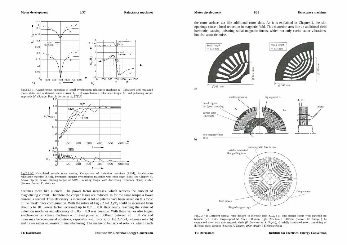
Motor development 2/37 Reluctance machines
TU Darmstadt Institute for Electrical Energy Conversion
Fig.2.2.6-1: Asynchronous operation of small synchronous reluctance machine: (a) Calculated and measured (dots) stator and additional stator current I3 , (b) asynchronous reluctance torque Ma and pulsating torque amplitude MP (Source: Bausch, Jordan et al, ETZ-A)
Fig.2.2.6-2: Calculated asynchronous starting: Comparison of induction machines (ASM), Synchronous reluctance machine (SRM), Permanent magnet synchronous machines with rotor cage (PSM, see Chapter 3). Above: speed, below: starting torque of SRM. Pulsating torque with decreasing frequency clearly visible (Source: Bunzel, E., elektrie). becomes more like a circle. The power factor increases, which reduces the amount of magnetizing current. Therefore the copper losses are reduced, as for the same torque a lower current is needed. Thus efficiency is increased. A lot of patents have been issued on this topic of the “best” rotor configuration. With the rotors of Fig.2.2.6-1 Xd/Xq could be increased from about 5 to 10. Power factor increased up to 0.7 ... 0.8, thus nearly reaching the value of induction machines and efficiency of 0.85 ... 0.9 was possible. With these values also bigger synchronous reluctance machines with rated power at 1500/min between 20 ... 50 kW and more may be economical solutions, especially with rotor a) of Fig.2.2.6-1, whereas rotor b) and c) are rather expensive in manufacturing. The magnetic barriers of rotor c), which reach
Motor development 2/38 Reluctance machines
TU Darmstadt Institute for Electrical Energy Conversion
the rotor surface, act like additional rotor slots. As it is explained in Chapter 4, the slot openings cause a local reduction in magnetic field. This distortion acts like an additional field harmonic, causing pulsating radial magnetic forces, which not only excite stator vibrations, but also acoustic noise.
a)
b)
c) Fig.2.2.7-1: Different special rotor designs to increase ratio Xd/Xq : a) Flux barrier rotors with punched-out barriers (left: Rated torque/speed 58 Nm / 1500/min, right: 265 Nm / 1500/min (Source: M. Kamper), b) segmented rotor with non-magnetic shaft (P. Lawrenson, S. Gupta), c) axially laminated rotor, containing of different stack sections (Source: F. Taegen, 1990, Archiv f. Elektrotechnik)

Motor development 3/1 PM machines with rotor cage
TU Darmstadt Institute for Electrical Energy Conversion
3. PM synchronous machines with cage rotor 3.1 Basic motor function and rotor design a) Basic motor function: Compared with the PM brushless DC drives of Chapter 1, the PM synchronous machines with cage rotor do not operate with a rotor position sensor. They consist – like the brushless DC machine – of a slotted stator with a three phase distributed AC winding, but the rotor is containing not only permanent magnets, but also a squirrel cage for asynchronous starting like the synchronous reluctance machine. Like the synchronous reluctance machines, the rotor may oscillate in speed against the stator field, which is rotating with synchronous speed, defined by stator frequency. Therefore the rotor cage, which in that case is induced by stator field, will generate cage currents, which will create reaction Lorentz forces with stator field, thus damping the oscillations very quickly (amortisseur). Rotor cage must be near air-gap to get a good flux linkage with stator field, therefore no surface mounted permanent magnets can be used (Fig.3.1-1). Permanent magnets are "buried" below the cage in the rotor.
Fig.3.1-1: Two pole PM synchronous machine with cage rotor and rare earth permanent magnets. Note non-magnetic (welded with non-magnetic steel) gap between N- and S-pole to reduce PM stray flux (Source: Siemens AG, Germany) PM synchronous machine may be therefore operated at grid (fixed voltage and frequency), starting asynchronously via the rotor cage, and after being pulled into synchronous speed by rotor permanent magnets, will run with synchronously rotating rotor like the previously discussed synchronous reluctance machine. No inverter is needed in that case. On the other hand, group drive with one big inverter feeding several PM machines in parallel, is also possible. They are started with variable frequency from zero to rated speed. Load steps at single motors will cause them to oscillate, but oscillations will be damped by rotor cage. If one motor is overloaded and pulled out of synchronism, it will be decelerated down to standstill by the load. Then, without changing inverter voltage and frequency, this single motor can be started up asynchronously again by the rotor cage. Conclusions: PM synchronous motor with squirrel cage operates without rotor position sensor, and may be operated also directly at the grid without any inverter.
Motor development 3/2 PM machines with rotor cage
TU Darmstadt Institute for Electrical Energy Conversion
b) Rotor design: Buried magnets will cause a big part of magnetic flux to stay within the rotor iron, thus not reaching the air gap and the stator winding (PM stray flux). This means a waste of expensive PM magnetic material. Therefore in Fig.3.1-1 a non-magnetic gap between rotor N- and S-pole is designed, increasing the magnetic resistance, thus reducing the rotor PM stray flux considerably. Buried magnets allow the advantage of flux concentration (Fig.3.1-2) with the flux concentration factor kM
pMM bk /2 . (3.1-1) In most simple case, rotor magnets are put with their direction of magnetization perpendicular to radial direction. Then, the maximum of rotor magnet breadth bM is theoretically given by the difference of rotor outer and inner diameter
2/)( riraM ddb , (3.1-2) yielding a flux concentration of
ra
ri
ra
rira
p
MM d
dp
pd
ddbk 12
2
2
. (3.1-3)
Fig.3.1-2: Comparison of rotor PM arrangement for (left) surface mounted and (right) buried magnets Example 3.1-1: Buried magnets: Flux concentration of radially inserted magnets: We assume 3.0/ rari dd . In order to get a flux concentration, this corresponds to the demand 1Mk .
Pole count 2p 2 4 6 8 kM 0.45 < 1 0.9 < 1 1.34 > 1 1.78 > 1
Table 3.1-1: Flux concentration with radial inserted rotor magnets is only possible for high pole count (at least 6 poles) Conclusions: Effective flux concentration with radial inserted magnets needs a high pole count (of at least six poles). By special arrangement of magnets not exactly in radial direction (Fig.3.1-3a), one gets increased breadth of magnets also four 4 pole machines, reaching values of 2/raM db . Now, also flux concentration for 4 pole machines is possible (Fig.3.1-4):

Motor development 3/3 PM machines with rotor cage
TU Darmstadt Institute for Electrical Energy Conversion
p
pddbkra
ra
p
MM
2
2
2 . (3.1-4)
Pole count 2p 4 6
kM 1.27 > 1 1.9 > 1 Table 3.1-2: Flux concentration with special arrangement of rotor magnets is also possible for 4 pole machines
Fig.3.1-3: Flux concentration with special arrangement of rotor magnets is also possible for 4 pole machines: a) Axial cross section: 1: PM main flux, 2: PM stray flux, 3: permanent magnets (PM), 4: non-magnetic flux barrier to reduce PM stray flux, 5: rotor cage, b) side view. (Siemens AG)
Fig.3.1-4: Flux concentration with special arrangement of rotor magnets: a) 4-pole rotor, b) 6-pole rotor (Siemens AG) Example 3.1-2: 4- and 6-pole machine with buried ferrite magnets: BR = 0.4 T, HC = 300 kA/m at 20°C, magnet height 15 mm, air gap 1mm, 06.1/)/(/ 00 CRM HB . Air gap flux density at no-load is calculated with (1.5.3-7), assuming ideal iron with
Fe . Note that according to Fig.3.1.3b the closed loops of flux lines pass one magnet (height hM) and two times the air gap .
M
M
M
R
hk
BB
0
21
Motor development 3/4 PM machines with rotor cage
TU Darmstadt Institute for Electrical Energy Conversion
Pole count 2p 4 6 kM 1.27 1.9
B / T 0.43 0.6 Table 3.1-2: Air gap flux density with ferrite magnets at 20°C, flux concentration for ratio hM/ = 15/1. Conclusions: Cheap PM synchronous machines can be built with ferrite magnets with pole count 4 with no-load air gap flux density amplitudes 0.4 T. Non-magnetic flux barriers are necessary to keep permanent magnet stray flux within limits. For the same reason also the rotor shaft is manufactured from non-magnetic steel, which more expensive than standard magnetic steel such as St37 or St60 material. 3.2 Motor performance at synchronous speed At synchronous speed of rotor n = nsyn, the stator fundamental flux wave and the rotor move with identical speed, so the rotor cage is not induced, as flux linkage of stator field with rotor cage is constant. Relative position of stator field to rotor d-axis depends on phase angle of stator current Is with respect to back EMF Up in stator winding, induced by rotor permanent magnets. If we decompose stator current in to by 90° phase shifted components Id and Iq, the stator field components, excited by them, will find different rotor magnetic paths, as shown in Fig. 3.2-1, where a very simple buried magnet rotor arrangement is depicted. It fits to the real buried magnet arrangement of Fig.3.1-3 and Fig.3.1-4, where we can see, that the magnets lie in the flux paths of d-axis. As magnet permeability is nearly equal to that of air 0)/( CRM HB (Example 3.1-2), the d-flux has to cross air gap and magnet, which both have a big "magnetic resistance". The q-flux only has to cross the air gap, because the rotor iron, where the cage is arranged, allows guidance of the flux lines with high iron permeability. Typical values are Ld/Lq = 0.5.
Fig.3.2-1: Simplified 2-pole arrangement with buried rotor magnets: The stator d-flux has to cross the rotor magnets, thus yielding a lower d-inductance (left). The stator q-flux can avoid the rotor magnets, which results in a higher q-inductance (right). Conclusions: In PM machines with buried rotor magnets the d-inductance Ld is usually lower than the q-inductance Lq : Ld < Lq. Thus is opposite to the relationships in synchronous reluctance machines, where Ld > Lq. Voltage equation per phase is
psqqsddsss UIjXIjXIRU . (3.2-1)
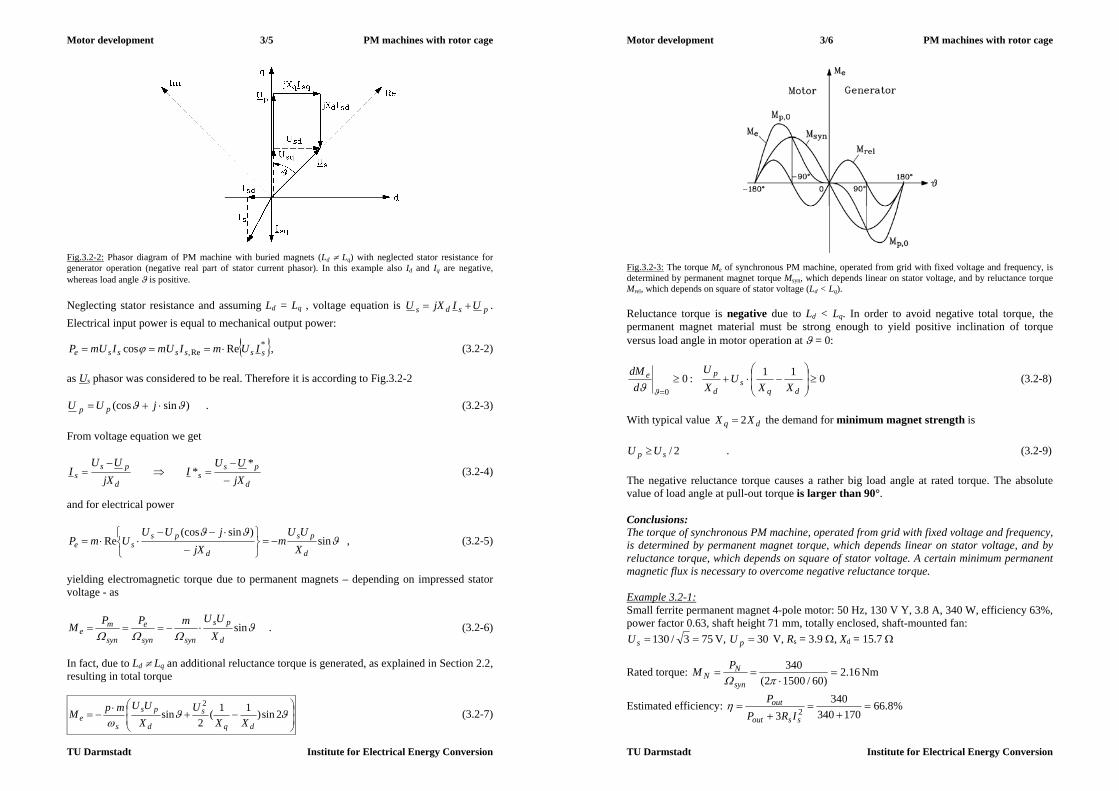
Motor development 3/5 PM machines with rotor cage
TU Darmstadt Institute for Electrical Energy Conversion
Fig.3.2-2: Phasor diagram of PM machine with buried magnets (Ld Lq) with neglected stator resistance for generator operation (negative real part of stator current phasor). In this example also Id and Iq are negative, whereas load angle is positive. Neglecting stator resistance and assuming Ld = Lq , voltage equation is psds UIjXU . Electrical input power is equal to mechanical output power:
*Re, Recos sssssse IUmImUImUP , (3.2-2)
as Us phasor was considered to be real. Therefore it is according to Fig.3.2-2
)sin(cos jUU pp . (3.2-3) From voltage equation we get
d
pss jX
UUI
d
pss jX
UUI
** (3.2-4)
and for electrical power
sin)sin(cos
Red
ps
d
psse X
UUm
jXjUU
UmP
, (3.2-5)
yielding electromagnetic torque due to permanent magnets – depending on impressed stator voltage - as
sind
ps
synsyn
e
syn
me X
UUmPPM . (3.2-6)
In fact, due to Ld Lq an additional reluctance torque is generated, as explained in Section 2.2, resulting in total torque
2sin)11(2
sin2
dq
s
d
ps
se XX
UXUUmpM (3.2-7)
Motor development 3/6 PM machines with rotor cage
TU Darmstadt Institute for Electrical Energy Conversion
Fig.3.2-3: The torque Me of synchronous PM machine, operated from grid with fixed voltage and frequency, is determined by permanent magnet torque Msyn, which depends linear on stator voltage, and by reluctance torque Mrel, which depends on square of stator voltage (Ld < Lq). Reluctance torque is negative due to Ld < Lq. In order to avoid negative total torque, the permanent magnet material must be strong enough to yield positive inclination of torque versus load angle in motor operation at = 0:
011:00
dqs
d
peXX
UXU
ddM
(3.2-8)
With typical value dq XX 2 the demand for minimum magnet strength is
2/sp UU . (3.2-9) The negative reluctance torque causes a rather big load angle at rated torque. The absolute value of load angle at pull-out torque is larger than 90°. Conclusions: The torque of synchronous PM machine, operated from grid with fixed voltage and frequency, is determined by permanent magnet torque, which depends linear on stator voltage, and by reluctance torque, which depends on square of stator voltage. A certain minimum permanent magnetic flux is necessary to overcome negative reluctance torque. Example 3.2-1: Small ferrite permanent magnet 4-pole motor: 50 Hz, 130 V Y, 3.8 A, 340 W, efficiency 63%, power factor 0.63, shaft height 71 mm, totally enclosed, shaft-mounted fan:
753/130 sU V, 30pU V, Rs = 3.9 , Xd = 15.7
Rated torque: 16.2)60/15002(
340
syn
NN
PM Nm
Estimated efficiency: %8.66170340
3403 2
ssout
out
IRPP

Motor development 3/7 PM machines with rotor cage
TU Darmstadt Institute for Electrical Energy Conversion
Synchronous pull-out torque: 75.27.153075
)60/15002(3
0
d
ps
synp X
UUmM Nm
Overload capability: 27.116.2/75.2/0 Np MM 3.3 Stress of permanent magnets at failures a) Asynchronous operation due to pull-out: When machine is loaded higher than maximum electromagnetic torque Mp0 (pull-out torque), rotor is pulled out of synchronism by load torque. Rotor is running asynchronously, rotor currents are induced in rotor cage, generating an asynchronous torque. In motor operation stator field, running at synchronous speed, is now faster than turning rotor. So stator field will oppose rotor permanent magnet flux a certain instants ("phase opposition", Fig.3.3-1), causing danger of irreversible demagnetization of rotor magnets.
Fig.3.3-1: Phasor diagram at asynchronous operation at phase opposition (stator resistance neglected) At that moment stator voltage and back EMF, induced by rotor magnets, are in phase opposition, causing a larger stator current flow than at rated condition:
Nd
pss I
XUU
I
(3.3-1)
Permanent magnet flux consists of stray flux and air gap flux:
pM (3.3-2) Demagnetizing stator flux s acts opposite to air gap flux p , penetrating the magnets. In order to completely demagnetize the magnets 0, sMresM , the stator flux must overcome not only p , but also the permanent magnet stray flux . So, the unavoidable magnet´s stray flux has also its benefit. Comparing with surface mounted magnets, where this stray flux is rather small, the demagnetizing stator flux must be bigger by the ratio
pp
p
1
to cancel permanent magnet flux completely.
Motor development 3/8 PM machines with rotor cage
TU Darmstadt Institute for Electrical Energy Conversion
Conclusions: Buried rotor magnets have a larger capability to withstand demagnetization by stator flux by the ratio of permanent magnet stray flux versus no-load air-gap flux. In the same way the stray flux also protects the rotor magnets from demagnetization, when rotor is dismounted from stator, as stray flux is closing over rotor iron parts, independent of the rotor being in stator bore or not. b) Sudden short circuit: At sudden short circuit of stator winding the current in stator winding may become rather big. The flux linkage of stator field – excited by this transient current flow – with rotor cage changes suddenly and is inducing the rotor cage. Due to Faraday´s law dtdui / the rotor cage currents are in phase opposition with stator current, hence exciting an additional rotor flux, which opposes the stator flux. Therefore stator and rotor flux are more or less cancelling. The rotor magnets, lying below the rotor cage, are therefore protected from big flux penetration of stator flux due to the screening effect of rotor cage. Conclusions: Rotor cage acts as an electromagnetic screen for the underlying buried magnets in case of stator current transients. 3.4 Torque at asynchronous starting Three torque components of different origin act together during asynchronous start-up. Two of these components have been already explained at start-up of synchronous reluctance machine with rotor squirrel cage. All three components consist of a constant torque component and an oscillating one. a) Asynchronous starting torque: Constant component is average asynchronous starting torque due to rotor cage currents with rotor frequency sr fsf (s: rotor slip) according to average stator inductance (Ld + Lq)/2. Due to difference (Lq - Ld) an oscillating part with frequency sfs 2 is added, as explained in Section 2.2. When reaching synchronous speed, both constant and oscillating torque vanish, as rotor cage is induced no longer, leading to vanishing rotor cage currents. Due to this asynchronous starting torque, the stator current also increases like in induction motors. Example 3.4-1: Permanent magnet synchronous six-pole motor, Ferrite magnets: Rated power at 50 Hz, 1000/min: 5.2 kW, rated current: 42 A, starting current: 220 A (524% !) b) Asynchronous reluctance torque: Rotor reluctance Lq Ld causes modulation of stator field, thus changing stator flux linkage with frequency sfs )12( , leading to additional induced stator voltage of that frequency and additional stator current I3. Fundamental space harmonics of air gap fields of stator currents Is and I3 produce constant asynchronous reluctance torque, which vanishes at s = 0.5 (Goerges-phenomenon), as at this speed no current I3 is induced. Both fields produce also an oscillating torque with rotor reluctance Lq Ld with frequency sfs 2 , which is minimum at s = 0.5 due to vanishing current I3.
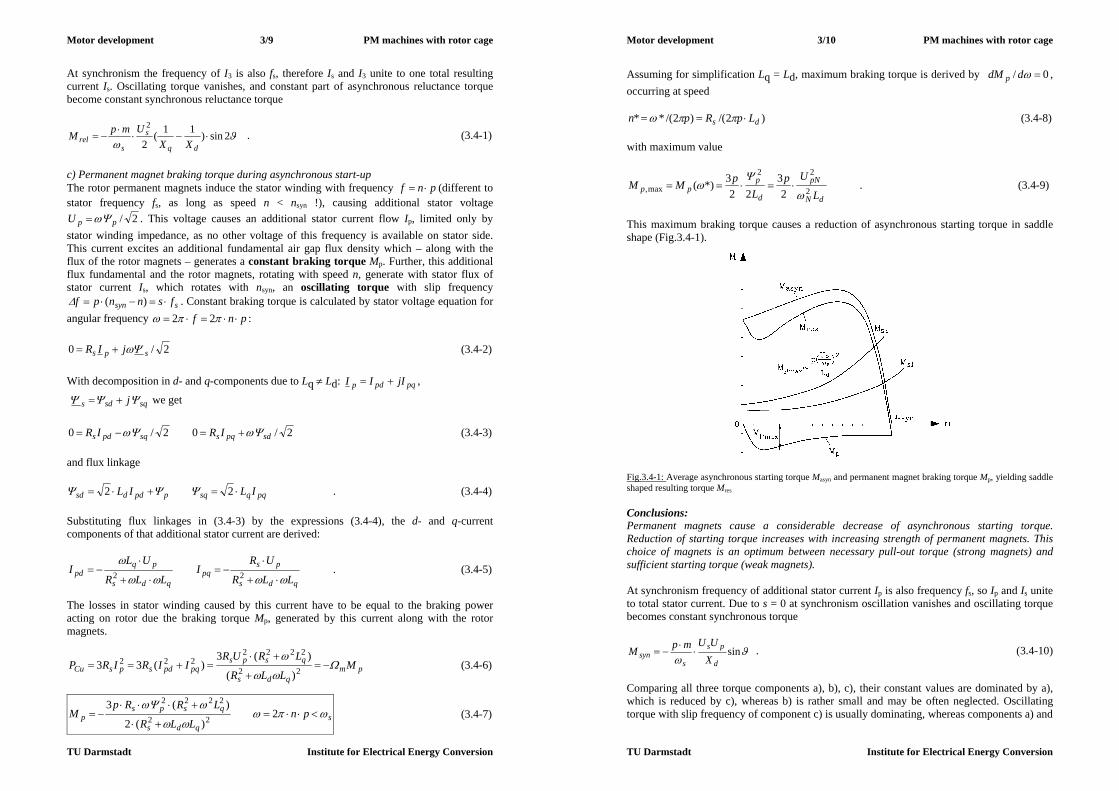
Motor development 3/9 PM machines with rotor cage
TU Darmstadt Institute for Electrical Energy Conversion
At synchronism the frequency of I3 is also fs, therefore Is and I3 unite to one total resulting current Is. Oscillating torque vanishes, and constant part of asynchronous reluctance torque become constant synchronous reluctance torque
2sin)11(2
2
dq
s
srel XX
UmpM . (3.4-1)
c) Permanent magnet braking torque during asynchronous start-up The rotor permanent magnets induce the stator winding with frequency pnf (different to stator frequency fs, as long as speed n < nsyn !), causing additional stator voltage
2/ppU . This voltage causes an additional stator current flow Ip, limited only by stator winding impedance, as no other voltage of this frequency is available on stator side. This current excites an additional fundamental air gap flux density which – along with the flux of the rotor magnets – generates a constant braking torque Mp. Further, this additional flux fundamental and the rotor magnets, rotating with speed n, generate with stator flux of stator current Is, which rotates with nsyn, an oscillating torque with slip frequency
ssyn fsnnpf )( . Constant braking torque is calculated by stator voltage equation for angular frequency pnf 22 :
2/0 sps jIR (3.4-2) With decomposition in d- and q-components due to Lq Ld: pqpdp jIII ,
sqsds j we get
2/02/0 sdpqssqpds IRIR (3.4-3) and flux linkage
pqqsqppddsd ILIL 22 . (3.4-4) Substituting flux linkages in (3.4-3) by the expressions (3.4-4), the d- and q-current components of that additional stator current are derived:
qds
pspq
qds
pqpd
LLR
URI
LLR
ULI
22 . (3.4-5)
The losses in stator winding caused by this current have to be equal to the braking power acting on rotor due the braking torque Mp, generated by this current along with the rotor magnets.
pmqds
qspspqpdspsCu M
LLR
LRURIIRIRP
22
2222222
)(
)(3)(33 (3.4-6)
sqds
qspsp pn
LLR
LRRpM
2
)(2
)(322
2222
(3.4-7)
Motor development 3/10 PM machines with rotor cage
TU Darmstadt Institute for Electrical Energy Conversion
Assuming for simplification Lq = Ld, maximum braking torque is derived by 0/ ddM p , occurring at speed
)2/()2/(** ds LpRpn (3.4-8) with maximum value
dN
pN
d
ppp
L
UpL
pMM 2
22
max, 23
223*)(
. (3.4-9)
This maximum braking torque causes a reduction of asynchronous starting torque in saddle shape (Fig.3.4-1).
Fig.3.4-1: Average asynchronous starting torque Masyn and permanent magnet braking torque Mp, yielding saddle shaped resulting torque Mres Conclusions: Permanent magnets cause a considerable decrease of asynchronous starting torque. Reduction of starting torque increases with increasing strength of permanent magnets. This choice of magnets is an optimum between necessary pull-out torque (strong magnets) and sufficient starting torque (weak magnets). At synchronism frequency of additional stator current Ip is also frequency fs, so Ip and Is unite to total stator current. Due to s = 0 at synchronism oscillation vanishes and oscillating torque becomes constant synchronous torque
sind
ps
ssyn X
UUmpM
. (3.4-10)
Comparing all three torque components a), b), c), their constant values are dominated by a), which is reduced by c), whereas b) is rather small and may be often neglected. Oscillating torque with slip frequency of component c) is usually dominating, whereas components a) and
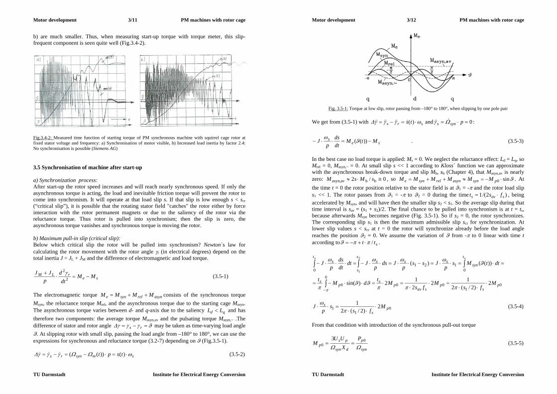
Motor development 3/11 PM machines with rotor cage
TU Darmstadt Institute for Electrical Energy Conversion
b) are much smaller. Thus, when measuring start-up torque with torque meter, this slip-frequent component is seen quite well (Fig.3.4-2).
Fig.3.4-2: Measured time function of starting torque of PM synchronous machine with squirrel cage rotor at fixed stator voltage and frequency: a) Synchronisation of motor visible, b) Increased load inertia by factor 2.4: No synchronisation is possible (Siemens AG) 3.5 Synchronisation of machine after start-up a) Synchronization process: After start-up the rotor speed increases and will reach nearly synchronous speed. If only the asynchronous torque is acting, the load and inevitable friction torque will prevent the rotor to come into synchronism. It will operate at that load slip s. If that slip is low enough s < scr (“critical slip”), it is possible that the rotating stator field "catches" the rotor either by force interaction with the rotor permanent magnets or due to the saliency of the rotor via the reluctance torque. Thus rotor is pulled into synchronism; then the slip is zero, the asynchronous torque vanishes and synchronous torque is moving the rotor. b) Maximum pull-in slip (critical slip): Below which critical slip the rotor will be pulled into synchronism? Newton´s law for calculating the rotor movement with the rotor angle r (in electrical degrees) depend on the total inertia J = JL + JM and the difference of electromagnetic and load torque.
serLM MM
dtd
pJJ
2
2 (3.5-1)
The electromagnetic torque asynrelsyne MMMM consists of the synchronous torque Msyn, the reluctance torque Mrel, and the asynchronous torque due to the starting cage Masyn. The asynchronous torque varies between d- and q-axis due to the saliency qd LL and has therefore two components: the average torque Masyn,av and the pulsating torque Masyn,~ .The difference of stator and rotor angle rs may be taken as time-varying load angle . At slipping rotor with small slip, passing the load angle from –180° to 180°, we can use the expressions for synchronous and reluctance torque (3.2-7) depending on (Fig.3.5-1).
smsynrs tspt )())(( (3.5-2)
Motor development 3/12 PM machines with rotor cage
TU Darmstadt Institute for Electrical Energy Conversion
Fig. 3.5-1: Torque at low slip, rotor passing from –180° to 180°, when slipping by one pole pair We get from (3.5-1) with srs ts )( and 0 psyns :
ses MtM
dtds
pJ ))((
. (3.5-3)
In the best case no load torque is applied: Ms = 0. We neglect the reluctance effect: Ld = Lq, so Mrel = 0, Masyn,~ = 0. At small slip s << 1 according to Kloss´ function we can approximate with the asynchronous break-down torque and slip Mb, sb (Chapter 4), that Masyn,av is nearly zero: 0/2 bbavasyn, sMsM , so sin0 psynasynrelsyne MMMMMM . At the time t = 0 the rotor position relative to the stator field is at 1 = - and the rotor load slip s1 << 1. The rotor passes from 1 = - to 2 = 0 during the time )2/(1 savs fst , being accelerated by Msyn, and will have then the smaller slip s2 < s1. So the average slip during that time interval is sav = (s1 + s2)/2. The final chance to be pulled into synchronism is at t = ts, because afterwards Msyn becomes negative (Fig. 3.5-1). So if s2 = 0, the rotor synchronizes. The corresponding slip s1 is then the maximum admissible slip scr for synchronization. At lower slip values s < scr at t = 0 the rotor will synchronize already before the load angle reaches the position 2 = 0. We assume the variation of from - to 0 linear with time t according to stt / .
01
00
0
0
0121
0
2)2/(2
12212)sin(
))(()(2
1
ps
psav
ps
ps
t
synss
s
s
st
s
Mfs
Mfs
MtdMt
dttMsp
Jssp
Jdsp
Jdtdtds
pJ
ss
01
1 2)2/(2
1p
s
s Mfs
sp
J
(3.5-4)
From that condition with introduction of the synchronous pull-out torque
syn
p
dsyn
psp
PX
UUM
0
03
(3.5-5)

Motor development 3/13 PM machines with rotor cage
TU Darmstadt Institute for Electrical Energy Conversion
for Ms = 0 the critical slip scr is found, below which the rotor will synchronize. The condition for synchronization is therefore: crss .
sLM
p
s
p
syncr fJJ
PppJ
Mss
)(2
/141 00
1 (3.5-6)
With Ms > 0 this slip decreases according to 0sMcrcr ss , with 1)0( sM . At a
small load torque its influence is negligible. At Ms/Mp0 = 0.9 critical slip has to be decreased already by 20 %. Then the critical slip rapidly decreases towards scr,min with
22.0)( 0 ps MM at Ms/Mp0 = 1.
Fig.3.5-2: Start-up torque with pull-in slip and pull-out torque Example 3.5-1: Barium ferrite six-pole synchronous permanent magnet motor, shaft height 160mm, totally enclosed, fan-cooled: 50 ... 150 Hz, 1000 ... 3000/min, 125 ... 380 V Y, 42 A, rated torque 49.7 Nm, overload capability 150%. Critical slip at 50 Hz and total momentum of inertia (motor and load): 1.5 kgm2 - Rated power at 50 Hz: 2.57.49)3/502()/2( NsN MpfP kW - Pull-out power: 8.75.10 Np PP kW
- Critical slip at Ms = 0: %8.7078.05.150
780023/502
1
crs
Example 3.5-2: Measured no-load start-up of barium ferrite synchronous motor with squirrel cage rotor (Fig.3.4-2) and additional momentum of inertia: a) Motor synchronizes, b) Increase of moment of inertia by factor 2.4: no synchronization possible. Note: The simplified calculation with critical slip will only reduce critical slip by factor
64.04.2/1 , whereas in reality no synchronization is possible. This can also be shown by numerical solution of dynamic equation (3.5-3).
Motor development 3/14 PM machines with rotor cage
TU Darmstadt Institute for Electrical Energy Conversion
Conclusions: After start-up motor will synchronize within certain limits of maximum load torque and inertia at critical slip. Once running at synchronism, motor will be stable until static pull-out torque is surpassed. Hence, a "hysteresis" between pull-in and pull-out exists (Fig. 3.5-2). 3.6 Permanent magnet synchronous motor features and application a) Motor features: Motors are usually designed with pole counts 2, 4, 6, buried magnets and squirrel cage, utilizing flux concentration at 4 and 6 poles. Many parts such as stator housings etc. may be used form induction motor mass production. This and the cheap ferrite magnets should yield rather low motor manufacturing costs. No rotor position encoder is necessary, so often inverter is operating with fixed ratio "voltage/frequency" U/f without any additional motor control. At low speed voltage has to be increased above that ratio to consider voltage drop
ss IR , which dominates at low speed. - Motors must have sufficient overload capability (usually Np MM 35.10 according to
IEC 34-1) - Machines are usually totally enclosed with shaft mounted fan or even without any cooling
(Fig. 3.6-2) - Quick braking of all motors is usually done by feeding stored kinetic energy in generator
mode back to inverter, where it is usually transferred to dissipated heat in braking resistance, which is connected to DC link via chopping transistor.
- If only one motor of group drive has to brake, it is short-circuited by additional switch, using the braking torque Mp for slowing down the machine. Another possibility is the use of DC current injection in two phases of motor winding to brake the motor (DC brake).
- Asynchronous starting heats up the rotor, as for each no-load start up the same amount of energy is transferred into rotor as heat as is stored in rotor mass as kinetic energy (3.6-1). Under load conditions the thermal energy, transferred to the rotor during start up, even surpasses the amount of stored kinetic energy.
2
2
,,m
kinrthermalr JWW (3.6-1)
- Usually three asynchronous starts immediately one after the other must be possible. For
thermal protection of stator winding temperature sensors such as PTC elements are used. - At high speed asynchronous starting would take too long time, overheating the machine.
In that case synchronous starting with variable stator frequency of inverter is used. High speed application: High speed is possible, typically up to 400 Hz with inverter supply. Example 3.6-1: Typical maximum speed of PM synchronous machines: Shaft height 80 mm: 400 Hz, 2-pole: 24000/min Shaft height 112 mm: 200 Hz, 2-pole: 12000/min,
4-pole: 6000/min, 6-pole: 4000/min
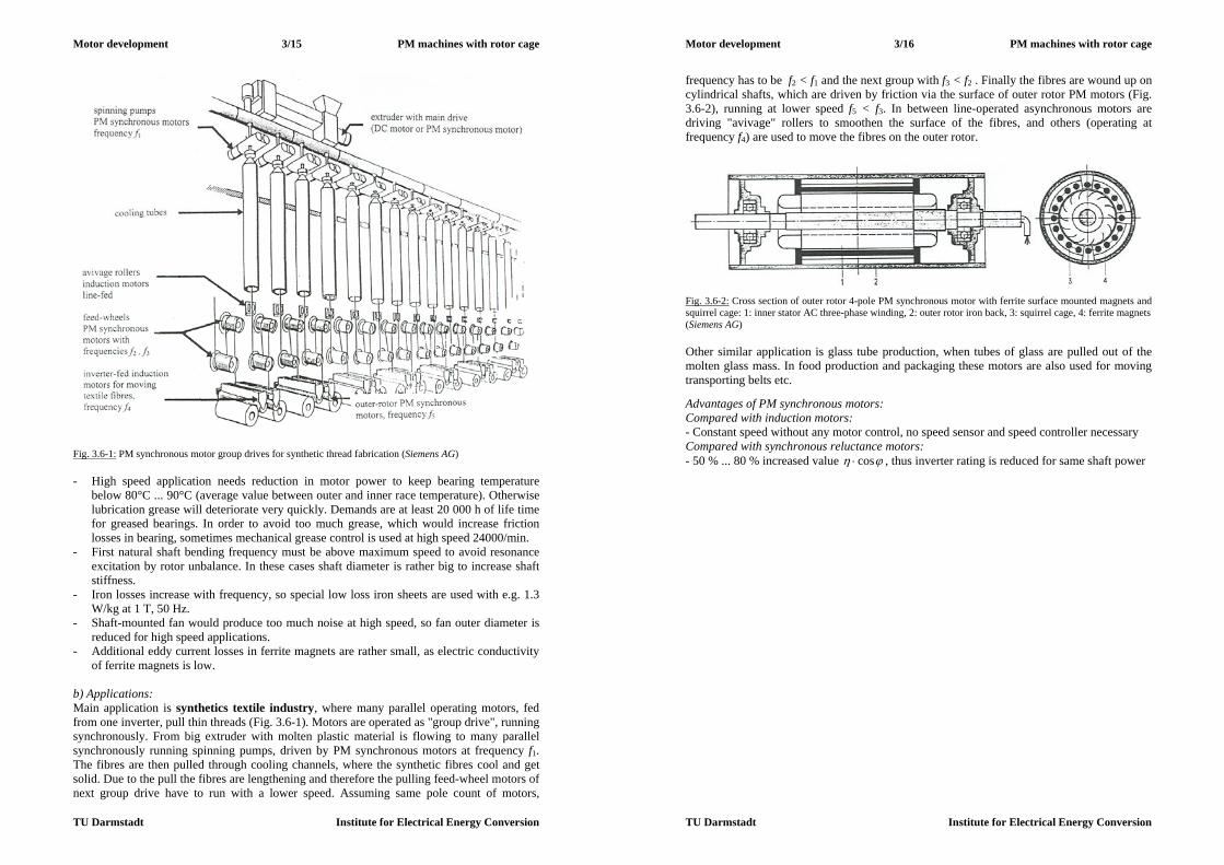
Motor development 3/15 PM machines with rotor cage
TU Darmstadt Institute for Electrical Energy Conversion
Fig. 3.6-1: PM synchronous motor group drives for synthetic thread fabrication (Siemens AG) - High speed application needs reduction in motor power to keep bearing temperature
below 80°C ... 90°C (average value between outer and inner race temperature). Otherwise lubrication grease will deteriorate very quickly. Demands are at least 20 000 h of life time for greased bearings. In order to avoid too much grease, which would increase friction losses in bearing, sometimes mechanical grease control is used at high speed 24000/min.
- First natural shaft bending frequency must be above maximum speed to avoid resonance excitation by rotor unbalance. In these cases shaft diameter is rather big to increase shaft stiffness.
- Iron losses increase with frequency, so special low loss iron sheets are used with e.g. 1.3 W/kg at 1 T, 50 Hz.
- Shaft-mounted fan would produce too much noise at high speed, so fan outer diameter is reduced for high speed applications.
- Additional eddy current losses in ferrite magnets are rather small, as electric conductivity of ferrite magnets is low.
b) Applications: Main application is synthetics textile industry, where many parallel operating motors, fed from one inverter, pull thin threads (Fig. 3.6-1). Motors are operated as "group drive", running synchronously. From big extruder with molten plastic material is flowing to many parallel synchronously running spinning pumps, driven by PM synchronous motors at frequency f1. The fibres are then pulled through cooling channels, where the synthetic fibres cool and get solid. Due to the pull the fibres are lengthening and therefore the pulling feed-wheel motors of next group drive have to run with a lower speed. Assuming same pole count of motors,
Motor development 3/16 PM machines with rotor cage
TU Darmstadt Institute for Electrical Energy Conversion
frequency has to be f2 < f1 and the next group with f3 < f2 . Finally the fibres are wound up on cylindrical shafts, which are driven by friction via the surface of outer rotor PM motors (Fig. 3.6-2), running at lower speed f5 < f3. In between line-operated asynchronous motors are driving "avivage" rollers to smoothen the surface of the fibres, and others (operating at frequency f4) are used to move the fibres on the outer rotor.
Fig. 3.6-2: Cross section of outer rotor 4-pole PM synchronous motor with ferrite surface mounted magnets and squirrel cage: 1: inner stator AC three-phase winding, 2: outer rotor iron back, 3: squirrel cage, 4: ferrite magnets (Siemens AG) Other similar application is glass tube production, when tubes of glass are pulled out of the molten glass mass. In food production and packaging these motors are also used for moving transporting belts etc. Advantages of PM synchronous motors: Compared with induction motors: - Constant speed without any motor control, no speed sensor and speed controller necessary Compared with synchronous reluctance motors: - 50 % ... 80 % increased value cos , thus inverter rating is reduced for same shaft power

Motor development 4/1 Induction machines
TU Darmstadt Institute for Electrical Energy Conversion
4. Induction machines 4.1 Significance and features of induction machines a) Basic function and different types of machines: Induction machines are in the power range of 100 W up to several MW the most prominent motor applications, being the "working horse" of industrial drive systems, but also in domestic applications and in traction drives. Recently many induction machines are used as generators in wind-mill applications in the power range of several 100 kW up to about 5 MW in off-shore plants. Induction machines are built usually in low power range up to about 3 kW with single-phase and for increased power with three-phase AC windings. Rotor winding is always short-circuited. Synchronously rotating stator field – excited by the stator current, which is driven by stator voltage supply - will induce according to Faraday´s law in short-circuited rotor winding rotor currents, as long as rotor rotates asynchronously to stator field:
synnn . Rotor currents produce with stator field tangential Lorentz forces, thus generating driving torque, if synnn (sub-synchronous operation = motor) and braking torque, if
synnn (super-synchronous operation = generator). That means that from stand-still n = 0 up to synchronous speed machine will rotate by itself as motor, whereas for generator a mechanical drive (turbine) has to drive the rotor faster than the rotating stator field. Ideal no-load is at synnn , a because in that case no flux change in rotor occurs and therefore no voltage is induced in rotor, thus no rotor currents flow, hence yielding zero torque. Inevitable friction causes always some small load torque, so rotor will also at no-load rotate slightly below synchronous speed. Difference in speed is normalized as slip
syn
syn
nnn
s
, (4.1-1)
which at stand still equals 1 and at synchronous speed is zero, being negative in generator operation. Rotor winding is most often a short circuited squirrel cage (Fig.4.1-1), which is cheap and robust, or sometimes a short circuited three-phase wire-wound rotor winding. Latter winding is usually star-connected with the three terminals connected to slip rings, being short circuited there. With these slip rings it is possible via sliding carbon brushes as contacts to connect additional rotor phase resistors. With this artificial increase of rotor resistance it is possible to raise motor starting torque at s = 1.
a) b) 1 2 3 4 5 6 Fig.4.1-1: Rotor of induction machine: a) Squirrel cage, consisting of (here skewed) rotor bars and two outer rings, short circuiting the bars. Bars are inserted in slots in rotor iron stack. Here cage consists of die-cast aluminium. Note the additional "fan blades" on the outside of the cage rings to generate additional circulating air flow for rotor cage cooling. b) Wire-wound three phase winding with slip-ring per phase: 1: Rotor iron stack, 2: rotor winding, 3: bandage fixing winding overhang, 4: winding connection to slip rings, 5: slip rings, 6: shaft (Siemens AG).
Motor development 4/2 Induction machines
TU Darmstadt Institute for Electrical Energy Conversion
Single-phase induction motors have stator windings, which consist of two phases a and b, displaced by half pole pitch, which are fed by currents ia and ib, phase shifted by 90°. Thus again a rotating stator field is generated, in the same way as it is done with three-phase winding, where the phases U, V, W are phase shifted by third of pole pair pitch, fed by three currents iU , iV and iW, phase shifted by 120°. So this machine in reality is a two-phase machine. As no two-phase grid exists, motors are operated from single phase grid UN = Ua. Second phase voltage Ub is generated by additional capacitor C, which is shifting current ib by 90° with respect to ia (Fig.4.1-2). As capacitor C is connected in series to stator phase winding b, this phase shift is only possible at certain slip (usually rated slip). At other speed values (e.g. no-load or starting) phase shift differs from 90°, so rotating field is not an ideal one. It changes amplitude during one revolution, thus causing additional losses due to eddy currents in stator and rotor iron stack, and additional pulsating torque, which causes the motor to vibrate with twice line frequency (e.g. at 50 Hz line frequency this is 100 Hz). For this reason this so-called "capacitor motor" is used only at low power below typically 3 kW due to the rather low efficiency of about 70% ... 75% in best case and due to the vibrations, mostly as 2- and 4-pole machines.
a) b) Fig.4.1-2: Two-phase induction motor: a) Operated from ideal two phase grid (which usually is not available in real world), b) operated from single phase grid, used for domestic application at low power below typically 3 kW b) Features of standard motors: As induction motors are widely used, these low voltage three-phase induction machines with squirrel cage rotor are standardized, independently from manufacturers, concerning - shaft height (= motor size), - distance of feet of motor housing or motor flange dimensions, - rated power, - shaft dimensions between shaft height 56 mm and 315 mm (see standard IEC 72). Low voltage is defined as less than 1000 V and is standardized 230 V, 400 V, 690 V. These motors are totally enclosed, surface cooled with air by shaft mounted fan (TEFC: totally enclosed fan cooled, Fig.4.1-3). Pole numbers are usually 2, 4, 6, 8. Motors with higher pole counts are already considered special machines. Example 4.1-1: Standardized shaft heights (mm): 56 63 71 80 90 100 112 132 160 180 200 225 250 280 315
Standardized motor power ( = mechanical shaft power = output power) (kW):
... 11 15 18.5 22 30 37 45 55 75 90 110 132 146 ...

Motor development 4/3 Induction machines
TU Darmstadt Institute for Electrical Energy Conversion
Fig.4.1-3: Standard induction motor: Motor elements for foot and flange type totally enclosed fan cooled squirrel cage machine (Siemens AG)
Fig.4.1-4: Cross section of standard induction machine (totally enclosed fan cooled squirrel cage machine), showing the main elements for foot (lower half of drawing) and flange type (upper half): 1: housing, 2: end-shield, 3: bearing lubrication, 4: bearing, 5: fan hood, 6: shaft-mounted fan, 7: shaft, 8: terminal box, 9: stator winding overhang, 10: stator iron stack, 11: rotor cage, 12: rotor iron stack (Siemens AG) Example 4.1-2: Standard induction motor (TEFC): Rated data: 7.5 kW, 230 / 400 V, D/Y, 26.5 / 15.2 A, 50 Hz, 1455/min, cos = 0.82 Shaft height 132 mm, four poles 2p = 4 Synchronous speed: min/1500/252/50/ spfnsyn Rated slip: %31500/)14551500(/)( synNsynN nnns
Motor development 4/4 Induction machines
TU Darmstadt Institute for Electrical Energy Conversion
Above motor frame size 315 mm still main dimensions of motor housings are standardized in IEC72 with shaft height 355 mm, 400 mm, 450 mm, but corresponding power ratings vary with different manufacturers, lying in the range of 355 kW ... 1000 kW for 4-pole machines. Most of the induction machines in the world are operated directly from the grid. Rotor is running with rated slip, which is usually only several percent, so speed is near synchronous speed at load and nearly synchronous speed at no-load (only friction is then loading the rotor). Conclusions: Line operated induction motors are regarded as fixes speed drives, as rated speed is only a few percentages below synchronous speed, so speed variation between no-load and load is small. c) Stator winding features: Note that on motor plate always rated voltage is line-to-line voltage and rated current is line current in motor cables. For delta connection line-to-line voltage is identical with phase voltage, but line current is larger by 3 than phase current. For star connection line-to-line voltage is larger by 3 than phase voltage, but line current and phase current are identical (Fig.4.1-5).
a) b) Fig.4.1-5: Three-phase stator winding can be connected either in a) delta connection or b) star connection Example 4.1-2: Standard induction motor (TEFC): Rated data: 7.5 kW, 230 / 400 V, D/Y, 26.5 / 15.2 A, 50 Hz, 1455/min, cos = 0.82
Winding connection delta star Phase voltage 230 V 230 V
line-to-line voltage 230 V 400 V Phase current 15.2 A 15.2 A Line current 26.5 A 15.2 A
From that data we can calculate electric input power for motor operation at rated slip with line values. Of course this input power is the same for delta or star connected stator winding. Delta connection (D): 865682.05.262303cos3 NNe IUP W
Star connection (Y): 865682.02.154003cos3 NNe IUP W Electric input power can also be calculated with phase values, which are identical for delta and star connection: 865682.02.152313cos3 sse IUP W.
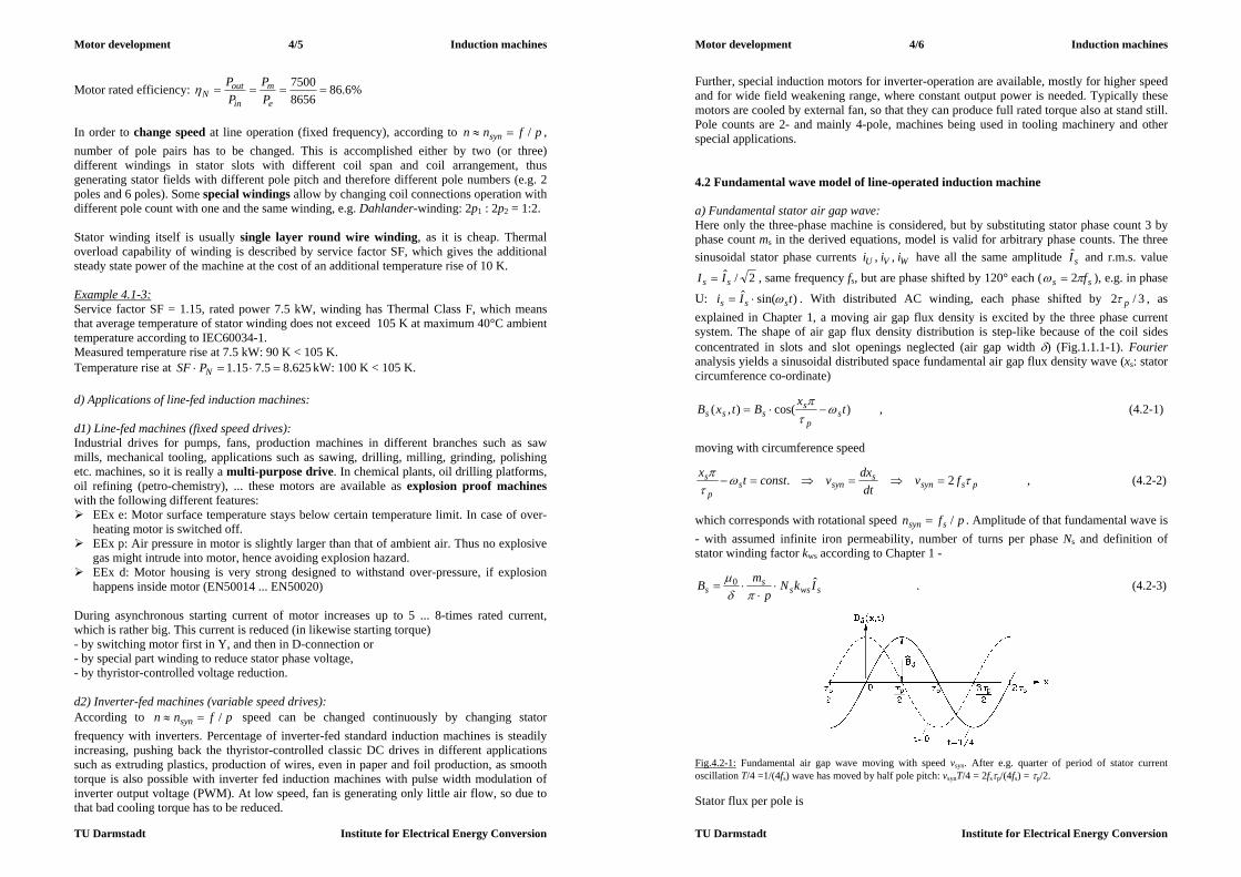
Motor development 4/5 Induction machines
TU Darmstadt Institute for Electrical Energy Conversion
Motor rated efficiency: %6.8686567500
e
m
in
outN P
PPP
In order to change speed at line operation (fixed frequency), according to pfnn syn / , number of pole pairs has to be changed. This is accomplished either by two (or three) different windings in stator slots with different coil span and coil arrangement, thus generating stator fields with different pole pitch and therefore different pole numbers (e.g. 2 poles and 6 poles). Some special windings allow by changing coil connections operation with different pole count with one and the same winding, e.g. Dahlander-winding: 2p1 : 2p2 = 1:2. Stator winding itself is usually single layer round wire winding, as it is cheap. Thermal overload capability of winding is described by service factor SF, which gives the additional steady state power of the machine at the cost of an additional temperature rise of 10 K. Example 4.1-3: Service factor SF = 1.15, rated power 7.5 kW, winding has Thermal Class F, which means that average temperature of stator winding does not exceed 105 K at maximum 40°C ambient temperature according to IEC60034-1. Measured temperature rise at 7.5 kW: 90 K < 105 K. Temperature rise at 625.85.715.1 NPSF kW: 100 K < 105 K. d) Applications of line-fed induction machines: d1) Line-fed machines (fixed speed drives): Industrial drives for pumps, fans, production machines in different branches such as saw mills, mechanical tooling, applications such as sawing, drilling, milling, grinding, polishing etc. machines, so it is really a multi-purpose drive. In chemical plants, oil drilling platforms, oil refining (petro-chemistry), ... these motors are available as explosion proof machines with the following different features: EEx e: Motor surface temperature stays below certain temperature limit. In case of over-
heating motor is switched off. EEx p: Air pressure in motor is slightly larger than that of ambient air. Thus no explosive
gas might intrude into motor, hence avoiding explosion hazard. EEx d: Motor housing is very strong designed to withstand over-pressure, if explosion
happens inside motor (EN50014 ... EN50020) During asynchronous starting current of motor increases up to 5 ... 8-times rated current, which is rather big. This current is reduced (in likewise starting torque) - by switching motor first in Y, and then in D-connection or - by special part winding to reduce stator phase voltage, - by thyristor-controlled voltage reduction. d2) Inverter-fed machines (variable speed drives): According to pfnn syn / speed can be changed continuously by changing stator frequency with inverters. Percentage of inverter-fed standard induction machines is steadily increasing, pushing back the thyristor-controlled classic DC drives in different applications such as extruding plastics, production of wires, even in paper and foil production, as smooth torque is also possible with inverter fed induction machines with pulse width modulation of inverter output voltage (PWM). At low speed, fan is generating only little air flow, so due to that bad cooling torque has to be reduced.
Motor development 4/6 Induction machines
TU Darmstadt Institute for Electrical Energy Conversion
Further, special induction motors for inverter-operation are available, mostly for higher speed and for wide field weakening range, where constant output power is needed. Typically these motors are cooled by external fan, so that they can produce full rated torque also at stand still. Pole counts are 2- and mainly 4-pole, machines being used in tooling machinery and other special applications. 4.2 Fundamental wave model of line-operated induction machine a) Fundamental stator air gap wave: Here only the three-phase machine is considered, but by substituting stator phase count 3 by phase count ms in the derived equations, model is valid for arbitrary phase counts. The three sinusoidal stator phase currents WVU iii ,, have all the same amplitude sI and r.m.s. value
2/ˆss II , same frequency fs, but are phase shifted by 120° each ( ss f 2 ), e.g. in phase
U: )sin(ˆ tIi sss . With distributed AC winding, each phase shifted by 3/2 p , as explained in Chapter 1, a moving air gap flux density is excited by the three phase current system. The shape of air gap flux density distribution is step-like because of the coil sides concentrated in slots and slot openings neglected (air gap width ) (Fig.1.1.1-1). Fourier analysis yields a sinusoidal distributed space fundamental air gap flux density wave (xs: stator circumference co-ordinate)
)cos(),( tx
BtxB sp
ssss
, (4.2-1)
moving with circumference speed
pssyns
synsp
s fvdt
dxvconsttx 2. , (4.2-2)
which corresponds with rotational speed pfn ssyn / . Amplitude of that fundamental wave is - with assumed infinite iron permeability, number of turns per phase Ns and definition of stator winding factor kws according to Chapter 1 -
swsss
s IkNp
mB ˆ0
. (4.2-3)
Fig.4.2-1: Fundamental air gap wave moving with speed vsyn. After e.g. quarter of period of stator current oscillation T/4 =1/(4fs) wave has moved by half pole pitch: vsynT/4 = 2fsp/(4fs) = p/2. Stator flux per pole is

Motor development 4/7 Induction machines
TU Darmstadt Institute for Electrical Energy Conversion
)sin(2cos),()(00
tBldxtxBldxtxBlt ssFepssp
ssFesssFes
pp
, (4.2-4)
which is pulsating with stator frequency and therefore induces each phase of stator winding according to Faraday´s law with "self-induced" voltage
)cos(2/)(, tBlNkdttdNku ssFepswsssswsssi
, (4.2-5) which may also be described with self-inductance Lsh e.g. for phase U, as it was already described in Chapter 1 for synchronous machine, which has identical stator winding arrangement:
Feps
wsshssshssil
pmkNLdtdiLu 2
20,
2)(/ (4.2-6)
As all voltages and currents vary sinusoidal, the advantage of complex calculus is usually used, e.g. self-induced voltage (with an arbitrarily chosen phase shift s)
tjssi
tjssissssissi
sss eUeUtUtu ,)(
,,, 2ReˆRe)cos(ˆ)( , (4.2-7)
where instead of time function )(, tu ssi the complex number sjssissi eUU
,, is used with r.m.s. value of Ui,ss . Thus we get instead of (4.2-6), considering the 90° phase shift from
)sin( ts of current to )cos( ts of voltage by multiplication with 1j :
shssssi ILjU , . (4.2-8) b) Induced rotor voltage and currents: Rotor cage may be considered as a short circuited winding system with mr = Qr rotor phases, as each rotor bar is one independent rotor phase with its bar current as rotor phase current. Each rotor phase consists only of one bar, which is a "coil" with a half-winding: Nr = 1/2. Therefore distributed winding per phase is possible, hence rotor winding factor is kwr = 1. Induced voltage per rotor phase (= per rotor bar) is calculated in the same way, defining mutual inductance Mrs between stator and rotor winding:
Feps
wsswrrrssrss
rwrrsil
pmkNkNMdtdiM
dttdNku 20,
2/)( (4.2-9)
srsrrsi IMjU , . (4.2-10) Note that due to rotor movement with speed n relative to stator space fundamental wave speed nsyn the rotor frequency is
sr fsf . (4.2-11) Rotor induced voltage per bar causes rotor bar currents Ir. The Qr sinusoidal rotor bar currents
rQrrr iii ,2,1, ...,, have all the same amplitude rI and r.m.s. value 2/ˆrr II , same
frequency fr, but are phase shifted by )//(2 pQr , because one pole pair - corresponding with pQr / rotor bars - is stator flux wave space period (Example 4.2-1).
Motor development 4/8 Induction machines
TU Darmstadt Institute for Electrical Energy Conversion
Example 4.2-1: Rotor cage with Qr = 28 rotor bars, induced be 4 four-pole stator wave. Phase shift between adjacent rotor bar currents is therefore: 7/)2/28/(2)//(2 pQr
Fig. 4.2-2: Squirrel cage rotor: a) Rotor cage with Qr = 28 rotor bars, induced by 4-pole stator wave. b) Rotor bar currents are phase shifted by /7. c) Fundamental rotor air gap wave: According to (4.2-7) actual rotor current values at each time instant is given by real part of complex rotor currents, which is e.g. for Example 4.2-1 at t = 0 vertical part of current phasors Ir in Fig.4.2-2. With actual value rotor current distribution e.g. at t = 0 (Fig.4.2-3) Ampere´s law yields the rotor air gap flux density Br and its m.m.f. rrr VBH )/( 0 again as step-like function with steps at rotor slot locations. Comparing with Fig. 1.1.1-1 we note, that step-like rotor flux density distribution fits much better to sinusoidal distribution than stator flux density step function. This is due to the much bigger phase number in rotor.
Fig. 4.2-3: Distribution of rotor bar currents and rotor m.m.f. V (proportional to air gap flux density in case of infinite iron permeability and constant air gap) along rotor circumference for example Qr/p = 14 at t = 0 Fourier analysis yields a sinusoidal distributed space fundamental air gap flux density wave (xr: rotor circumference co-ordinate, fixed with rotor reference frame)
)cos(),( tx
BtxB rp
rrrr
, (4.2-12)
moving with circumference speed prrsyn fv 2, or pfn rrsyn /, relative to rotor, having the amplitude
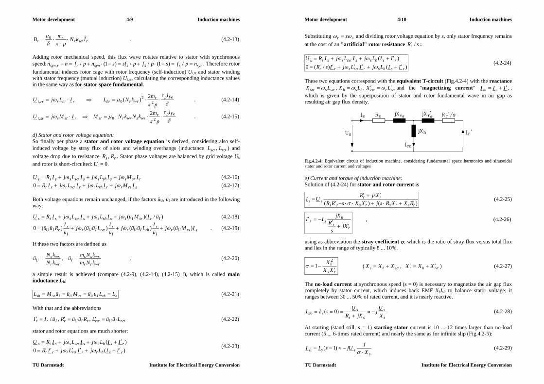
Motor development 4/9 Induction machines
TU Darmstadt Institute for Electrical Energy Conversion
rwrrr
r IkNp
mB ˆ0
. (4.2-13)
Adding rotor mechanical speed, this flux wave rotates relative to stator with synchronous speed: synssssynrrsyn npfspfpsfsnpfnn /)1(//)1(/, . Therefore rotor fundamental induces rotor cage with rotor frequency (self-induction) Ui,rr and stator winding with stator frequency (mutual induction) Ui,sr, calculating the corresponding inductance values in the same way as for stator space fundamental.
Fepr
wrrhrrhrrrril
pmkNLILjU 2
20,
2)( . (4.2-14)
Fepr
wsswrrsrrsrssril
pmkNkNMIMjU 20,
2 . (4.2-15)
d) Stator and rotor voltage equation: So finally per phase a stator and rotor voltage equation is derived, considering also self-induced voltage by stray flux of slots and winding overhangs (inductance rs LL , ) and voltage drop due to resistance rs RR , . Stator phase voltages are balanced by grid voltage Us and rotor is short-circuited: Ur = 0.
rsrssshsssssss IMjILjILjIRU (4.2-16)
srsrrrhrrrrrr IMjILjILjIR 0 (4.2-17) Both voltage equations remain unchanged, if the factors üU, üI are introduced in the following way:
)/)(( IrsrIssshsssssss üIMüjILjILjIRU (4.2-18)
srsUrI
rrhIUr
I
rrIUr
I
rrIU IMüj
üILüüj
üILüüj
üIRüü )()()()(0 . (4.2-19)
If these two factors are defined as
wrrr
wsssI
wrr
wssU kNm
kNmükNkNü , , (4.2-20)
a simple result is achieved (compare (4.2-9), (4.2-14), (4.2-15) !), which is called main inductance Lh:
hrhIUrsUIsrsh LLüüMüüML (4.2-21) With that and the abbreviations
rIUrrIUrIrr LüüLRüüRüII ,,/ (4.2-22) stator and rotor equations are much shorter:
)(0)(
rshrrrrrr
rshsssssss
IILjILjIRIILjILjIRU
(4.2-23)
Motor development 4/10 Induction machines
TU Darmstadt Institute for Electrical Energy Conversion
Substituting sr s and dividing rotor voltage equation by s, only stator frequency remains at the cost of an "artificial" rotor resistance sRr / :
)()/(0)(
rshsrrsrr
rshsssssss
IILjILjIsRIILjILjIRU
(4.2-24)
These two equations correspond with the equivalent T-circuit (Fig.4.2-4) with the reactance
rrrhshsss LXLXLX ,, and the "magnetizing current" rsm III , which is given by the superposition of stator and rotor fundamental wave in air gap as resulting air gap flux density.
Fig.4.2-4: Equivalent circuit of induction machine, considering fundamental space harmonics and sinusoidal stator and rotor current and voltages e) Current and torque of induction machine: Solution of (4.2-24) for stator and rotor current is
)()( rsrsrsrs
rrss RXXRsjXXsRR
XjsRUI
(4.2-25)
rr
hsr
Xjs
RjXII
, (4.2-26)
using as abbreviation the stray coefficient , which is the ratio of stray flux versus total flux and lies in the range of typically 8 ... 10%.
rs
hXX
X
2
1 ( shs XXX , rhr XXX ) (4.2-27)
The no-load current at synchronous speed (s = 0) is necessary to magnetize the air gap flux completely by stator current, which induces back EMF XhIs0 to balance stator voltage; it ranges between 30 ... 50% of rated current, and it is nearly reactive.
s
s
ss
sss X
Uj
jXRU
sII
)0(0 (4.2-28)
At starting (stand still, s = 1) starting stator current is 10 ... 12 times larger than no-load current (5 ... 6-times rated current) and nearly the same as for infinite slip (Fig.4.2-5):
ssss X
UjsII
1)1(1 (4.2-29)
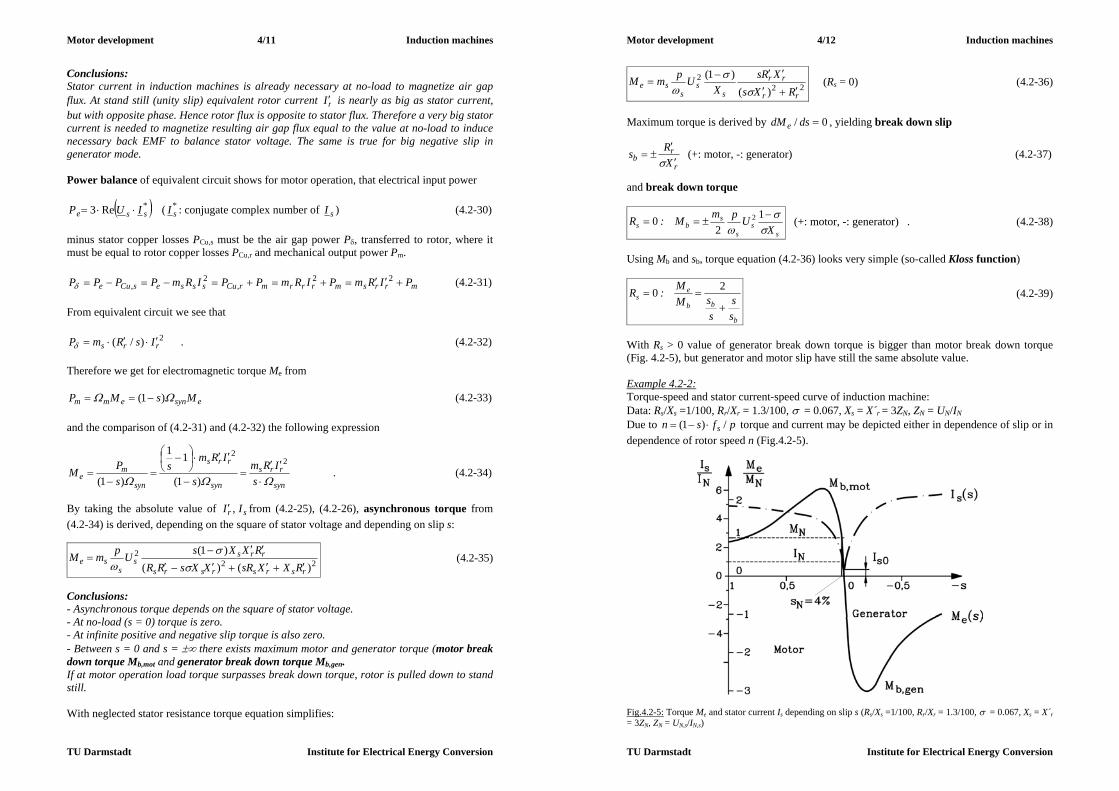
Motor development 4/11 Induction machines
TU Darmstadt Institute for Electrical Energy Conversion
Conclusions: Stator current in induction machines is already necessary at no-load to magnetize air gap flux. At stand still (unity slip) equivalent rotor current rI is nearly as big as stator current, but with opposite phase. Hence rotor flux is opposite to stator flux. Therefore a very big stator current is needed to magnetize resulting air gap flux equal to the value at no-load to induce necessary back EMF to balance stator voltage. The same is true for big negative slip in generator mode. Power balance of equivalent circuit shows for motor operation, that electrical input power
*Re3 sse IUP ( *sI : conjugate complex number of sI ) (4.2-30)
minus stator copper losses PCu,s must be the air gap power P, transferred to rotor, where it must be equal to rotor copper losses PCu,r and mechanical output power Pm.
mrrsmrrrmrCusssesCue PIRmPIRmPPIRmPPPP 22,
2, (4.2-31)
From equivalent circuit we see that
2)/( rrs IsRmP . (4.2-32) Therefore we get for electromagnetic torque Me from
esynemm MsMP )1( (4.2-33) and the comparison of (4.2-31) and (4.2-32) the following expression
syn
rrs
syn
rrs
syn
me s
IRms
IRms
sPM
2
2
)1(
11
)1( . (4.2-34)
By taking the absolute value of sr II , from (4.2-25), (4.2-26), asynchronous torque from (4.2-34) is derived, depending on the square of stator voltage and depending on slip s:
222
)()()1(
rsrsrsrs
rrss
sse
RXXsRXXsRRRXXsUpmM
(4.2-35)
Conclusions: - Asynchronous torque depends on the square of stator voltage. - At no-load (s = 0) torque is zero. - At infinite positive and negative slip torque is also zero. - Between s = 0 and s = there exists maximum motor and generator torque (motor break down torque Mb,mot and generator break down torque Mb,gen. If at motor operation load torque surpasses break down torque, rotor is pulled down to stand still. With neglected stator resistance torque equation simplifies:
Motor development 4/12 Induction machines
TU Darmstadt Institute for Electrical Energy Conversion
222
)()1(
rr
rr
ss
sse
RXsXRs
XUpmM
(Rs = 0) (4.2-36)
Maximum torque is derived by 0/ dsdM e , yielding break down slip
r
rb X
Rs
(+: motor, -: generator) (4.2-37)
and break down torque
ss
s
sbs X
UpmM:R
12
0 2 (+: motor, -: generator) . (4.2-38)
Using Mb and sb, torque equation (4.2-36) looks very simple (so-called Kloss function)
b
bb
es
ss
ssM
M:R
20 (4.2-39)
With Rs > 0 value of generator break down torque is bigger than motor break down torque (Fig. 4.2-5), but generator and motor slip have still the same absolute value. Example 4.2-2: Torque-speed and stator current-speed curve of induction machine: Data: Rs/Xs =1/100, Rr/Xr = 1.3/100, = 0.067, Xs = X´r = 3ZN, ZN = UN/IN Due to pfsn s /)1( torque and current may be depicted either in dependence of slip or in dependence of rotor speed n (Fig.4.2-5).
Fig.4.2-5: Torque Me and stator current Is depending on slip s (Rs/Xs =1/100, Rr/Xr = 1.3/100, = 0.067, Xs = X´r = 3ZN, ZN = UN,s/IN,s)

Motor development 4/13 Induction machines
TU Darmstadt Institute for Electrical Energy Conversion
f) Rotor current displacement for increased starting torque: Fig.4.2-5 shows 5 times rated current as starting current, but starting even a little bit lower than rated torque. How to increase starting torque ? According to (4.2-34) increase of rotor resistance will increase torque at s = 1:
syn
rrse
IRmsM
2)1(
. (4.2-40)
For wire wound rotor induction machine with slip rings it is possible via sliding carbon brushes as contacts to connect additional rotor phase resistors to increase rotor resistance to raise motor starting torque at s = 1. But how is this possible with cage rotors ? If rotor bar is made with big bar height hbar ("deep bar"), the rotor slot stray flux will be rather big. It oscillates with rotor frequency, which equals stator frequency at stand still.
Fig. 4.2-6: Rotor deep bar : a) Rotor slot stray flux lines crossing the bar, b) rotor bar current density without current displacement, c) distribution of rotor slot stray flux density With Ampere´s law we get for rotor stray flux density a linear rise within bar and constant value above bar:
barC
rQ bxJbxHsdH )(
barr
r
r
barQ h
xbI
bbxJxB
00)( barhx 0 (4.2-41)
r
barQ b
IB 0 Qbar hxh (4.2-42)
Fig. 4.2-7: Eddy current IFt in deep bar excites additional slot flux density opposite to slot stray flux BQ, which is excited by bar current Ir
Motor development 4/14 Induction machines
TU Darmstadt Institute for Electrical Energy Conversion
This rotor slot flux induces according to Faraday´s law dtdu Qi / an additional voltage in the bar, which causes eddy current IFt flow (Ft: Foucault-current) in the bar. Due to negative sign in Faraday´s law direction of eddy current flow is as to excite an additional slot flux density BQFt which is opposing the original slot flux density (Fig. 4.2-7). Superposition of bar current and eddy current yields increased current density at upper bar edge and reduction of current density at bottom of slot (Fig. 4.2-8).
a) b) c) Fig. 4.2-8: Current displacement in deep bar at frequency fs in comparison to DC current situation (near slip s = 0). a) Slot and bar cross section with slot stray flux lines, b) bar current density distribution with/without current displacement, c) slot flux density distribution with/without current displacement As current flows mainly in upper part of deep bar, this acts like an increase of rotor resistance, which is easily understood by the following simplified current density distribution. Assume that current flows only in bar section height dE with increased density J~, then we get
Rdh
bdlRJdbJhbI
E
bar
barE
FeEbarbarbarr ~~ (4.2-43)
Conclusions:
Rotor bar resistance is increased from DC value barbar
Febh
lR
by a factor 1
E
barR d
hk .
The effect of current displacement decreases with decreasing rotor frequency. It is most prominent at stand still and vanishes at rated slip, where rotor frequency is below 2 Hz. Thus increased losses due to increased rotor resistance occur only at starting (big slip), where torque increase is needed, but NOT at rated operation. Although total stray flux is reduced by eddy current, the deep bar causes a rather big rotor stray flux and therefore an increased stray coefficient . According to (4.2-38) break down torque is decreased by /)1( , so increase of starting torque due to current displacement causes decrease of break down torque (Fig. 4.2-9). Resulting speed-torque curves are classified by so-called rotor classes, which defines the ratio of starting torque versus rated torque and the saddle of the torque-speed curve. Torque needs to be bigger than load torque to allow motor to run up. As voltage may vary by +/- 5% (voltage range A according to EN 60034-1), the torque may be lower by about 10% in reality (Fig.4.2-10). Example 4.2-3: Rotor class 16 means, that at UN-5% the motor is capable to start against load torque of 160%MN.

Motor development 4/15 Induction machines
TU Darmstadt Institute for Electrical Energy Conversion
i) Fig. 4.2-9: Increase of starting torque and decrease of break down torque due to current displacement: No or low current displacement: a) round bar, b) oval bar Big current displacement: c) deep bar, d) wedge bar, e) step bar, f), g) h): double cage – bronze upper cage to increase resistance i) Corresponding torque-speed curve
Fig. 4.2-10: Example of cage induction motors classified according to rotor classes KL
Motor development 4/16 Induction machines
TU Darmstadt Institute for Electrical Energy Conversion
4.3 Voltage limits and premium efficiency machines a) Voltage limits: Induction motors operated directly from the grid shall comply with several operational demands, which are specified in standards IEC 60034-1, -2 and other parts of this international electric machinery standard. Some features are: - sufficiently high starting torque M1 (expressed in per unit of rated torque, see Chapter 4.2) - sufficiently low starting current I1 (usually 5 ... 7 times rated current) - sufficient overload capability (breakdown torque at least 1.6-times rated torque) - sufficient minimum start-up torque ("saddle minimum" of M(n)-curve) - good efficiency (= low losses) - low acoustic noise Standard low voltage level, which is stator voltage, supplied by public grid, is 400 V (line-to-line), which may vary within European Community between +/- 10%. Example 4.3-1: Grid voltage limits: 400V+/-10%: minimum: 360 V, maximum: 440 V If induction motor is fed with increased voltage, stator flux linkage is also increased according to simplified stator voltage equation (Rs = 0):
ssrshsssss jIILjILjU )( (4.3-1) As flux linkage is excited by stator and rotor current, magnetizing current is increased by increased stator voltage. Increased saturation will occur.
mhrshsss ILIILIL )( (4.3-2)
Fig.4.3-1: Measured no-load voltage *) versus no-load current, which in that special case is identical with magnetizing current (270 kW, high-speed 2 pole induction motor, inverter operation at fs = 270 Hz, winding in delta connection. *) Fundamental harmonic line-to-line voltage versus rms-value of no-load current.

Motor development 4/17 Induction machines
TU Darmstadt Institute for Electrical Energy Conversion
Due to iron saturation (Fig.4.3-1) an increase of 10% voltage, thus an increase of about of 10% stator flux linkage, means an increase of magnetizing current of MORE than 10%. At no load this increase of magnetizing current can easily be measured just by raising stator voltage (Fig.4.3-1) and corresponds directly with increase of stator current, as rotor current at no-load is zero. Too low voltage causes a drop of breakdown torque by square of voltage. Example 4.3-2: Rated voltage: 400V, operational voltage: 360 V, reduction in breakdown torque:
81.09.0)400/360()/(/ 222 sNsbNb UUMM Breakdown torque Mb is reduced by almost 20%. If motor is operated with constant rated load torque MN, slip increases above rated slip according to Kloss function. Kloss function in range of rated (and therefore small) slip may be simplified:
b
b
bb
es s
s
ss
ssM
MR
22:0 (4.3-3)
For constant electromagnetic torque Me = MN a decrease of breakdown torque by 0.81 (or 19%) means an increase of slip by 1/0.81 (about +25%). Therefore stator and rotor current increase in the same way, thus increasing motor winding losses. Conclusions: At increased voltage stator current may rise dramatically, if machine is highly saturated. This current increase may overheat motor winding. The increase of flux causes increased iron losses. At reduced stator voltage (and therefore reduced motor flux) the motor, operated a rated torque, will consume increased current, as torque is given by product of current and flux. Increased current might overheat windings. Optimum motor design at rated voltage and rated torque is therefore minimum current consumption as a balance between flux (and therefore magnetizing current) and load current (or rotor current). According to IEC 60034-1 motors must be capable of operating at rated voltage ±5% ("voltage range A") and rated power at a maximum surplus in motor temperature rise of 10 K above the temperature rise limit of the used insulation material. At rated voltage ±10% ("voltage range B") the windings will be overheated much more, therefore no long term operation at these voltage limits is recommended. Example 4.3-3: Rated voltage: 400V, Voltage range A: 400 V ±5% = 380 ... 420 V. Thermal class of insulation material F (IEC 60034-1): Temperature rise limit for motors with rated power below 200 kW: 105 K over 40°C ambient temperature. Allowable temperature rise of winding at voltage limits: 115 K. b) Premium efficiency motors: Industrial electric drives consume a considerable amount of energy all over the world. Example 4.3-4: In Germany is an example for an industrialized country. Power consumption in 2004 was: a) Electrical energy consumption: 18 % of total energy consumption = 504 TWh b) Industrial electrical energy consumption: 47 % of a) = 237 TWh c) Conversion to mechanical energy: 69% of b) = 163 TWh
Motor development 4/18 Induction machines
TU Darmstadt Institute for Electrical Energy Conversion
With an average efficiency increase of 4% of electromechanical energy conversion by e.g. premium efficiency motors, which could be realized for 50% of installed drive power, one gets an energy saving of 1635.004.0 TWh = 3.3 TWh per year (= 8760 h), which amounts to power delivery of a power plant with 3.3 TWh / 8760 h = 377 MW. This value is increasing, as energy consumption increases. Most power plants in Germany are thermal power plants. New plants have an optimum efficiency of 50%, e.g. if a combined cycle plant is used. In this case saving of thermal input power is 754 MW. In reality, many of German thermal power plants are of older type with an average efficiency of only about 35 %. Therefore saving would even lead to a reduction of 1077 MW thermal input power. Conclusions: Efficiency improvement of industrial motors has not only an economical, but also an environmental impact.
Fig.4.3-2: Typical catalogue efficiency and shaft height AH of four pole induction motors: standard with normal efficiency (---------), motors with increased efficiency (“-motors”) (___________) In United States the Energy Policy Act (EPACT) was established (1997), demanding that manufacturers of standard induction motors (TEFC) selling motors on the US American market, must offer 2-pole and 4-pole squirrel-cage induction motors with increased efficiency values up to a rating of 90 h.p. with predefined values of efficiency at rated operation. By aiming at 2- and 4-pole motors in that power range the main part of standard motor applications is included. The measurement of efficiency must be done according to international standards by certified laboratory to ensure quality standard. In Europe several motor manufacturers had offered standard induction motors with increased efficiency for long (Fig. 4.3-2), but no legislative act up to now is forcing all manufacturers to do so. Shortly after the EPACT the Community of European Motor Manufacturers (CEMEP) has agreed on a voluntary agreement with the Commission of European Community (EC) to offer for the European market 2- and 4-pole motors with increased efficiency in a similar way as the EPACT demands. Due to the different standard power and voltage ratings in USA and Europe (e.g. USA: 460 V, 60 Hz, EC: 400 V, 50 Hz) the motor types with and their predefined increased efficiency values are slightly different from EPACT demands. According to this voluntary CEMEP agreement 2-and 4-pole motors in power range between 1 ... 100 kW are available in three efficiency classes (Fig. 4.3-3):

Motor development 4/19 Induction machines
TU Darmstadt Institute for Electrical Energy Conversion
Cheap standard motors with usual efficiency values: Efficiency class eff3 Standard motors with increased efficiency: Efficiency class eff2 Premium efficiency motors at increased motor price: Efficiency class eff1 It is the long term aim that in the future only two motor classes will exist: eff2 and eff1. Since 1999 and 2003 already a considerable shift in sold motors from class eff3 to class eff2 was experienced in Western Europe.
Fig.4.3-3: Definition of efficiency classes eff1, eff2, eff3 for four pole standard induction motors in power range 1 ... 100 kW according to voluntary agreement between CEMEP and commission of EC Losses in induction machines are separated into stator and rotor losses or in no-load and load losses, mainly eddy current and hysteresis losses in the iron stack, winding and cage losses due to electric current flow, friction losses in bearings and sealing and windage losses due to power consumption of shaft mounted fan.
No-load losses Load losses Stator losses Copper losses in winding PCu,0
Iron losses in iron stack PFe Additional no-load losses
Copper losses in winding PCu,s Additional load losses
Rotor losses Friction and windage losses Pfr+w Additional no-load losses
Cage losses due to rotor current PrAdditional load losses
Table 4.3-1: Losses in induction machine at no-load and load (rated load) Distortion of air gap flux density distribution by slot openings: - stator and rotor tooth flux pulsation losses at no-load, being increased at loadStep-like distribution of air gap flux density due to arrangement of windings in slots: - additional harmonic rotor bar currents, losses increased by current displacement due to the rather high frequencies, - additional harmonic currents in stator winding, - eddy current losses in rotor surface, if the rotor insulation between the iron sheets is bridged by the tooling of the rotor surface to ensure small mechanical air gap, The additional harmonic rotor bar currents may flow as inter-bar currents between adjacent rotor bars, especially when the rotor is skewed, because there is usually no insulation between rotor iron stack and rotor bars. Iron saturation causes also deviation of air gap flux density from ideal sinus, mainly by introducing an additional third space harmonic, which is inducing - additional harmonic rotor currents in the cage at load - circulating stator currents in delta connected stator winding, Flux density leaves iron stack at the stack ends axially, penetrating the end sheets. Therefore radial stack lamination cannot suppress eddy current flow, thus - additional iron losses in the end sheets due to axial flux components occur Magnetic flux is not contained only to iron stack and air gap, but a certain stray flux penetrates also massive metallic (conductive) parts such as housing and shaft, causing - additional eddy current losses in massive metallic parts Table 4.3-2: Over-view on main components of additional losses.
Motor development 4/20 Induction machines
TU Darmstadt Institute for Electrical Energy Conversion
In rotor frequency at no-load is almost zero and at load it is small (e.g. rated slip: 5%, stator frequency: 50 Hz, then rotor frequency is 5.25005.0 sr fsf Hz), so nearly no rotor iron losses (eddy current losses and hysteresis losses in rotor iron stack) will occur. Additional losses (stray load losses) are caused mainly by the fact that the air gap flux density is not distributed like an ideal sinus flux density wave, but rather step-like due to the arrangement of winding and cage in slots. Thus additional high-frequency stator and rotor currents are induced, causing additional losses. There exist a lot of further reasons, why these additional losses may arise and can become rather significant, especially at high speed motors (Table 4.3-2). Power flow in motor is according to Chapter 4.2 given by electric stator input power Pin, which feeds stator winding losses PCu,s and stator core losses PFe. Stator additional losses at no-load are usually included in stator core losses in standard measurements according to IEC 60034-2. Power flow from stator to rotor via air gap P = Pin - PCu,s – PFe is feeding rotor cage losses (slip losses) Pr and friction and windage losses Pfr+w. Remaining power may separated into mechanical output power Pout, directly measured via the shaft torque e.g. with a torque-meter and speed sout MnP 2 and additional load losses Pad1 = P - Pr - Pout . Example 4.3-4: Measured loss balance of a 2.55 kW, 8-pole, totally enclosed induction motor with shaft mounted fan (IEC 60034-2): ambient temperature 20°C, winding temperature rise: 61.5 K
Slip at rated power 2.55 kW sN = 4.44 % Speed / torque n / Ms 860 /min / 28.4 Nm
Measured electrical input power Pin 3254 W Stator copper losses PCu,s 385 W (55 %)
Stator iron losses PFe 133 W (19 %) Rotor cage losses PsPr 121 W (17 %) Additional load losses Pad,1 47 W (7 %)
Friction and windage losses Pfr+w 14 W (2 %) Total losses Pd 700 W (100 %)
Output power outP 2554 W Efficiency 78.49 %
Table 4.3-3: Example of measured loss balance and efficiency of a Thermal Class B 8-pole induction motor at 60 Hz, 440 V Y according to "direct" method a) of IEC 60034-2 at rated load Please note, that efficiency of on specific motor varies with load. At no-load output power is zero, therefore efficiency is zero. Considering no-load losses Pd0 as independent from load, and load losses Pd1 as caused by copper losses in winding and cage: rssd IIIP ~,~ 2
1 , one gets a simple loss model for estimating change of efficiency with load (Fig.4.3-4): - Motor flux depending on voltage and frequency, which are both fixed, so flux is constant - No-load losses Pd0 independent of motor load M - Motor load M depends on flux and current Is, so varies linear with current - Load losses Pd1 mainly ohmic losses in stator and rotor, depending on square of current Is 22
10 ~~., MIPconstP sdd
)/(10
NNoutddout
out MMPPPPP
P
(4.3-4)

Motor development 4/21 Induction machines
TU Darmstadt Institute for Electrical Energy Conversion
NNdNNdNd PkPMMPkPPkP 112
1100 ,)/(, (4.3-5) Optimum (maximum) efficiency is given for 0/ dMd , yielding the result:
NddoptN PPMM 10 // (4.3-6)
At this load point the no-load losses and the load losses are equal: 10 dd PP , yielding a maximum possible efficiency of
)/(2//
010
10max
NdNdd
Ndd
PPPPPP
. (4.3-7)
Fig.4.3-4: Variation of losses Pd and efficiency with output power Pout. Here it is assumed that no-load losses are constant and 0.1PN , load losses at rated power are 0.14PN and vary with the square of output power Example 4.3-5: Efficiency varies with varying load: Motor data: 2.0,06.0,)/(2.0,06.0 10
210 kkMMPPPP NNdNd
NMMmmm
m /,2.006.0 2
Load M/MN 0 0.25 0.5 0.75 1.0 Efficiency 0 77.52 % 81.96 % 81.30 % 79.36 %
Table 4.3-4: Load depending efficiency at constant voltage line supply Here: 55.02.0/06.0/ optNMM , Ndd PPP 06.010 ,
8203.006.022.0/06.0
2.0/06.0max
Conclusions: In order to increase motor rated efficiency, motor utilization (Power/volume) must not exceed a certain limit in order to get rated efficiency at the optimum value. At other load points (higher or lower load) efficiency will decrease.
Motor development 4/22 Induction machines
TU Darmstadt Institute for Electrical Energy Conversion
How can maximum efficiency be increased for a certain motor ? - By using low loss iron sheets iron losses are be reduced (e.g. 1.7 W/kg instead of 2.3 W/kg). - By using copper instead of aluminium cage rotor conductivity rises by 57/34 = 167%, thus reducing rotor resistance and losses. - By increasing slot number per pole and phase q (e.g. from 3 to 4) the number of steps of the air gap flux density distribution is increased by 4/3, but the steps itself get smaller by 3/4. Hence the flux density distribution is more sinusoidal, and the additional losses are reduced. - Increase of slot number also increases the cooling surface of winding, as the winding surface towards iron is increased according to the slot surfaces. Thus the temperature rise of winding is reduced, and therefore the winding resistance is lower, leading to lower losses (and a longer life span of insulation material). Conclusions: A lot of rules exist to increase efficiency, but usually all these measures increase motor manufacturing costs. So motors with increased efficiency are usually more expensive. Example 4.3-6: Influence of winding temperature on efficiency for a 8-pole motor, 2.55 kW, 60 Hz, 440 V:
Temperature rise 60 K 105 K Warm phase resistance 4.11 Ohm 4.7 Ohm
Slip at rated power 2.55 kW 4.44 % 5.05 % Speed / torque 860 /min / 28.4 Nm 854 /min / 28.6 Nm Input power 3198 W 3268 W
Stator copper losses 380 W 434 W Iron losses 133 W 133 W
Rotor cage losses 121 W 137 W Friction and windage losses 14 W 14 W
Output power 2550 W 2550 W Efficiency 79.74 % 78.03 %
Table 4.3-5: Reduced efficiency due to increased temperature rise caused by inferior cooling, ambient 20°C 4.4 Space harmonic effects in induction machines Although time variation of stator voltage and current is sinusoidal due sinusoidal grid supply, spatial distribution of flux density in air gap is NOT, as winding is located in slots. So the spatial distribution of flux density is INDEPENDENT of the kind of time variation of feeding winding currents. It depends ONLY on winding arrangement in slots and air gap geometry. In Chapters 4.1 ... 4.3 only effects of fundamental sine wave of air gap flux density distribution was considered. In reality also the higher space harmonics of stator and rotor field distribution have to be considered to understand measured torque-speed curves of induction machines. For simplification influence of slot openings will be neglected here. With slots with infinitesimal small slot openings the air gap flux density is step-like distributed, as explained in Chapter 1 for stator and in Chapter 4.2 for rotor field. 4.4.1 Field space harmonics and current time harmonics at sinusoidal stator voltage a) Stator field spatial harmonics: Sinus time-function of stator voltage Us causes sinus time-function stator current Is to flow in stator winding. Fourier analysis of stator air gap field of a ms-phase (usually three-phase)

Motor development 4/23 Induction machines
TU Darmstadt Institute for Electrical Energy Conversion
stator winding concentrated in qmpQ ss 2 stator slots, fed by a time-sinusoidal ms-phase
stator current system with phase shift sm/2 between phases, amplitude 2sI and frequency fs, yields following result: The step-like air gap flux density distribution ),(, txB ss along stator circumference co-ordinate xs can be represented by an infinite sum of sinus spatial-distributed flux density waves. Summing index is the ordinal number . With increasing wave length , wave speed sfv and amplitudes ,B are decreasing.
1,, )cos(),(
txBtxB s
p
sss ss f 2 (4.4.1-1)
For ms = 3: gms 21 = 1, -5, 7, -11, 13, -17, ... (4.4.1-2) (g: integer number: ,...3,2,1,0 g )
sw
ss I
kN
pmB
,0
,2
(no iron saturation considered) (4.4.1-3)
/2 p (4.4.1-4)
The alternatively changing sign of ordinal numbers indicates that waves move alternatively with fundamental in the same direction (clockwise) or in opposite direction (counter-clockwise). No even ordinal numbers occur, as flux density distribution is symmetrical to abscissa. This means, the shape of north and south pole of flux density distribution is identical. No odd ordinal numbers dividable by the phase number occur due to the distinct number of phases. Winding factor kw, is defined by distribution factor kd, , which considers how many slots per pole q are occupied by one phase, and by pitch factor kp, , which considers if span per coil W equals pole pitch or not.
,,, dpw kkk (4.4.1-5)
)2
sin(
)2
sin(
,
qmq
mk
s
sd
,
2sin,
pp
Wk (4.4.1-6)
Example 4.4.1-1: Fourier analysis of flux density distribution of a three-phase, four pole, two-layer winding with q = 2, W/p = 5/6. Winding and air gap data:
1 mm; turns per coil 5cN ; all coils per phase connected in series, so number of parallel winding paths is a = 1; bore diameter dsi = 80 mm; phase current (r.m.s): Is = 30 A . We get: Qs/p = 12 slots per pole pair, pole pitch: 8.62)2/( pdsip mm and turns per phase: 401/524/2 aNqpN cs . Flux density amplitude of fundamental:
95.0301933.040
232
001.0104
12 7
1,01,
sw
ss I
kN
pmB T
Motor development 4/24 Induction machines
TU Darmstadt Institute for Electrical Energy Conversion
Relative amplitudes winding factor wave speed at fs = 50 Hz 1/ BB (%) kp, kd, kw, v (m/s) 1 100 0.966 0.966 0.933 6.28 -5 1.4 0.259 0.259 0.067 - 1.26 7 1.0 0.259 -0.259 -0.067 0.9
-11 9.1 0.966 -0.966 -0.933 - 0.6 13 7.7 -0.966 -0.966 0.933 0.5 -17 0.4 -0.259 -0.259 0.067 - 0.37 19 0.38 -0.259 0.259 -0.067 0.33
Table 4.4.1-1: Fourier analysis of stator spatial air gap flux density distribution, excited by a three-phase, four pole, two-layer winding with q = 2, W/p = 5/6, delivers a sum of travelling flux density waves in the air gap
Fig. 4.4.1-1: Air gap flux density at t = 0 ( 2/2,2 sWVsU IiiIi ) and fundamental and first slot harmonic waves for q = 2, W/p = 5/6. Fig. 4.4.1-1 shows the corresponding flux density distribution, Fig. 1.1.1-1 the one for q = 2, but W/p = 1, which is the case for single-layer winding. Obviously Fig. 4.4.1-1 fits better to a sinus than Fig. 1.1.1-1, which is accomplished by the chording (pitching) of the coil span. Due to this chording the winding factor for 5th and 7th space harmonic is almost zero, again for 17th, 19th, and so on, whereas for 11th, 13th, 23rd, 25th, and so on, winding factor is the same as for fundamental. Therefore these wave amplitudes (so-called "slot harmonics") dominate the wave spectrum. Their ordinal number is
gp
Qs 1 (g: integer number: ,...3,2,1,0 g ) , (4.4.1-7)

Motor development 4/25 Induction machines
TU Darmstadt Institute for Electrical Energy Conversion
yielding here = -11, 13, -23, 25, ... These harmonics are caused by the steps in air gap distribution (see Fig.4.4.1-1), so the average value of wave length of the first pair of slot harmonics is equal to slot pitch (step length). Example 4.4.1-2: Winding: q = 2, W/p = 5/6, slot pitch 12/2 pQ . Ordinal number of first pair of slot harmonics: = -11, 13 Wave length of first pair of slot harmonics: 13/2,11/2 1311 pp Average value of wave length: 12/22/)( 1311 p Conclusions: Wave spectrum of air gap flux density distribution is dominated in chorded two-layer windings (apart from fundamental) by slot harmonic waves. In unchorded single-layer winding also the 5th and 7th harmonic must be considered. b) Rotor cage field spatial harmonics, excited by rotor current Ir: Stator fundamental field = 1 moves with synchronous velocity psssyn ffv 21 (or synchronous speed nsyn, respectively), whereas rotor is turning with speed n, defining slip
synsyn nnns /)( . Therefore stator fundamental flux linkage with rotor cage changes with rotor frequency sr fsf , inducing sinusoidal rotor voltage Ui,r according to Faraday´s law. This voltage, as shown in Chapter 4.2, causes the sinus time-function rotor current Ir, to flow in adjacent bars with phase shift rQp /2 , exciting also a step-like air gap flux density distribution ),(, txB rr along rotor circumference co-ordinate xr. It can in the same way be represented by an infinite sum of sinus spatial-distributed flux density waves. Summing index is the ordinal number . With increasing wave length and wave speed rfv is decreasing, amplitudes ,B are also decreasing with 1/. As each bar represents a rotor phase (mr = Qr), consisting of 1/2 turn per phase (Nr = 1/2), winding factor is always unity (kwr, = 1). Thus, we adopt (4.4.1-1) for rotor cage:
1,, )cos(),(
txBtxB r
p
rrr rr f 2 (4.4.1-8)
gpQr )/(1 (g: integer number: ,...3,2,1,0 g ) (4.4.1-9)
rr I
pQB
1
2120
, (no iron saturation considered) (4.4.1-10)
p2
(4.4.1-11)
The alternatively changing sign of ordinal numbers indicates again that waves move alternatively with fundamental in the same direction (clockwise) or in opposite direction (counter-clockwise). As each bar represents a phase, each spatial harmonic is a slot harmonic. Equations for ordinal numbers (4.4.1-7) and (4.4.1-9) are identical. Wave velocities with respect to rotor are
Motor development 4/26 Induction machines
TU Darmstadt Institute for Electrical Energy Conversion
//2, synpsrr vsfsfv . (4.4.1-12) With respect to stator we see that rotor co-ordinate xr plus the distance of rotor surface movement gives corresponding stator co-ordinate xs. As rotor surface velocity mv is given by slip s or rotor speed )1( snn syn respectively: pssynm fsvsv 2)1()1( , we get
tvxx mrs (4.4.1-13) and
)))1((cos())(
cos(),( ,,, tssx
Bttvx
BtxB sp
sr
p
mss
. (4.4.1-14)
Therefore speed of rotor space harmonics with respect to stator is
)/1(, ssvvvv synmr . (4.4.1-15) Example 4.4.1-3: Fourier analysis of flux density distribution of a cage with 28 rotor bars, exciting a four pole field distribution. Stator frequency is 50 Hz. Winding and air gap data:
1 mm; 2/1cN ; bore diameter dsi = 80 mm; bar current (r.m.s): Is = 240 A, slip: s = 5%. We get: Qr/p = 14 slots per pole pair, pole pitch: 8.62)2/( pdsip mm, vm = 5.97 m/s. Flux density amplitude of fundamental:
95.024011
21
2282
001.0104
11
212 7
01,
rr I
pQB T
relative
amplitudes winding factor wave speed with respect
to rotor to stator 1/ BB (%) kw, rv , (m/s) v
1 100 1 0.31 6.28 -13 7.6 1 - 0.024 5.95 15 6.7 1 0.02 6.0 -27 3.7 1 - 0.011 5.96 29 3.4 1 0.01 5.98
Table 4.4.1-2: Fourier analysis of rotor spatial air gap flux density distribution, excited by rotor current, which is induced by four pole stator fundamental field (stator frequency fs = 50 Hz) Conclusions: All rotor space harmonics – excited by rotor current Ir - are slot harmonics, containing therefore less harmonics than stator field. Rotor field fundamental runs – independently of rotor speed - synchronously with stator field fundamental, thus producing the constant asynchronous torque Me at any speed. This is the torque described by Kloss function in Chapter 4.2. This rotor fundamental induces stator therefore with stator frequency fs with the voltage rsrssri IMU , .

Motor development 4/27 Induction machines
TU Darmstadt Institute for Electrical Energy Conversion
c) Stator harmonic currents, induced by rotor cage field spatial harmonics: Rotor space harmonics 1 induce stator according to (4.4.1-14) with frequency
ssff sr )1(, , (4.4.1-16) causing small additional stator time-harmonic currents to flow, which usually are harmless and therefore most often are neglected in further considerations. Nevertheless, if asynchronous machine is used as a generator, these currents have to be considered as they distort total stator current and may cause electromagnetic interference with tele-communication lines (EMI). Only rotor space harmonics can induce the stator winding. For the induced stator voltage is zero due to the stator winding arrangement. Example 4.4.1-4: Frequencies of harmonic stator currents, induced by rotor flux density space harmonics distribution: 4-pole motor with data of Example 4.4.1-3: Cage with 28 rotor bars, stator frequency: 50 Hz, slip 0.05.
Frequency of stator current harmonics
Is stator winding induced?
fr, / Hz - 1 50 Yes: 1
-13 615 Yes: 13 15 715 No: 15 -27 1280 No: 27 29 1380 Yes: 29
Table 4.4.1-3: Frequencies of harmonic stator currents, induced by rotor flux density space harmonics distribution (stator frequency fs = 50 Hz) Conclusions: As operational slip is usually small (s 0), frequency of stator harmonic current may be estimated for zero slip, showing that this frequency is proportional to rotor slot number.
pQgfpQgfff rsrssr //1, Example 4.4.1-5: Measured stator current including harmonic stator currents, induced by rotor flux density space harmonics distribution. 2-pole motor, 3 kW, 380 V Y, 50 Hz, 6.2 A, cage with 22 rotor bars, rated slip 0.05. - Stator line-to-line peak voltage value: 5373802 V (measured: 535 V)
- Stator current peak value: 77.82.62 A (measured: 8.84 A) Ordinal numbers of rotor space harmonics: 23,211/221/1 pQr
Corresponding stator current harmonic frequencies:
:21 21 : This space harmonic does not induce the stator winding!
:23 23 : 109505.0)05.01(2350, rf Hz
Motor development 4/28 Induction machines
TU Darmstadt Institute for Electrical Energy Conversion
Fig. 4.4.1-2: Loaded 2-pole 3 kW cage induction motor at sinusoidal voltage supply: a) Measured stator line-to-line voltage, b) measured stator phase current, showing stator harmonic currents with 1095 Hz (roughly 22x50 Hz) d) Harmonic rotor bar currents, induced by stator spatial field harmonics: Stator space harmonics 1 move with velocity /syns vfv (or speed
/, synsyn nn ) much more slowly than rotor. Slip of these harmonics (harmonic slip) is
)1(1,
, ssn
nns
syn
syn
(4.4.1-17)
These stator space harmonics therefore induce rotor cage with frequency
)1(1, sffsf ssr , (4.4.1-18) causing small additional rotor time-harmonic bar currents Ir, to flow. As pole number of the stator harmonics is p 2 , phase shift between adjacent harmonic bar currents is rQp /2 .

Motor development 4/29 Induction machines
TU Darmstadt Institute for Electrical Energy Conversion
Example 4.4.1-6: Cage induction motor, stator frequency 50 Hz, no-load s = 0. Rotor cage with 28 bars, induced by stator space harmonic = -5. Harmonic slip 60151)1(15 ss Rotor cage harmonic frequency: 3005065, sr fsf Hz Phase shift between adjacent bar currents: 6.12828/2)5(360/360 rQp . Rotor bar currents:
Bar 1 Bar 2 Bar 3 Bar 4 etc. )cos(ˆ tIi rr )cos(ˆ
tI rr )2cos(ˆ tI rr )3cos(ˆ
tI rr ...
Rotor bar currents rIi ˆ/ e.g. at t = 0: Bar 1
2 3 4 5 6 7 8 9 10 11 12 13 14
1 -0.6 -0.2 0.9 -0.9 0.2 0.6 -1 0.6 0.2 -0.9 0.9 -0.2 0.6
Fig. 4.4.1-3: The cage rotor reacts to 10-pole inducing stator field wave with a ten pole rotor field: The 5th stator harmonic ( = 10 poles per fundamental pole pair) induces in the cage (7 bars/pole) rotor harmonic bar currents with phase shift (5/7), which excite according to Ampere´s law a 10-pole rotor field distribution. As number of bars per 10 poles is only 1.4, the approximation of sinus curve by cage field is rather coarse, but contains a 10-pole Fourier fundamental, which fits to the 10-pole stator sinus field wave. Conclusions: Rotor harmonic bar currents Ir excite a step-like air gap field with a fundamental of the same pole number as the inducing stator field harmonic: . Amplitude of this fundamental is calculated with the same Fourier formula (4.4.1-10), but now considering as exciting current Ir .
,...2,1,0
12120
,,
ggp
Q
Ip
QB
r
rr
(no iron saturation considered) (4.4.1-19)
Rotor bar harmonic currents rI can be calculated by taking the same rotor voltage equation of Chapter 4.2, but considering now the parameters of the -th stator space harmonic.
Motor development 4/30 Induction machines
TU Darmstadt Institute for Electrical Energy Conversion
dtdiMdt
tdNku srs
srwrrsi /
)(,,
(4.4.1-20)
Flux per pole of -th stator space harmonic is small, - as pole pitch is smaller by 1/ than fundamental, - as flux density amplitude is smaller by /,wsk instead of wsk than fundamental amplitude.
Thus harmonic flux per pole ,s is smaller by factor )/( 2, wsws kk than fundamental flux,
therefore also mutual and self inductance of air gap field is decreased by this factor.
Fepswsswrrrs
l
pm
kNkNM
22,02
(4.4.1-21)
srssrsi IMjsU , . (4.4.1-22) The Fourier space fundamental of rotor flux density distribution 5 (Fig.4.4.1-3) induces rotor cage with rotor frequency ss due to self-induction with voltage Ui,rr .
Feprwrrrhrrhsrri
l
pm
kNLILjsU
222
0,2
)( . (4.4.1-23)
So finally rotor voltage equation is derived, considering also self-induced voltage by stray flux of slots and winding overhangs (inductance rL ), voltage drop due to resistance rR , and that rotor is short-circuited: Ur = 0.
srssrrhsrrsrr IMjsILjsILjsIR 0 (4.4.1-24) With 2/1, rrr NQm and rsrhrwsss MLQkNm )/2( we get for the rotor harmonic current
srhrsr
rhsrwsssr I
LLjsRLQkNm
jI
)(/
)/2(
, (4.4.1-25)
which corresponds with an equivalent circuit Fig.4.4.1-4a for rotor cage, which closely resembles to T-equivalent circuit, but where now harmonic slip s is introduced. But note: Fig. 4.4.1-3 shows, that the actual step-like field distribution differs considerably from the fundamental, so a more thorough analysis considers also the self-induction in the rotor cage not only from the rotor fundamental , but also the self-induction from all other Fourier space harmonics of the rotor field. Thus the self-induction voltage (4.4.1-23) is enlarged by a factor 2/1 (which is not proven here):
r
rQp
Qp/
)/sin(
(4.4.1-26)
This additional harmonic self-induction voltage rrhsrri ILjsU )1/1( 2
, is usually considered in (4.4.1-25) by adding it to the stray inductance (Fig. 4.4.1-4b):
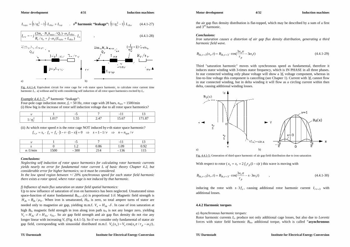
Motor development 4/31 Induction machines
TU Darmstadt Institute for Electrical Energy Conversion
rrhr LLL 1/1 2 . th harmonic “leakage”: rhL1/1 2 (4.4.1-27)
srhrsr
rhsrwsssr I
LLjsRLQkNmjI
)(/
)/2(
, (4.4.1-28)
a) b) Fig. 4.4.1-4: Equivalent circuit for rotor cage for -th stator space harmonic, to calculate rotor current time harmonic Ir a) without and b) with considering self induction of all rotor space harmonics excited by Ir Example 4.4.1-7: th harmonic “leakage”: Four-pole cage induction motor, fs = 50 Hz, rotor cage with 28 bars, nsyn = 1500/min (i) How big is the increase of rotor self induction voltage due to all rotor space harmonics?
1 -5 7 -11 13 2/1 1.017 1.55 2.47 15.67 171.87
(ii) At which rotor speed n is the rotor cage NOT induced by-th stator space harmonic? //110)1(1, synssr nnssffsf
1 -5 7 -11 13 s 0 1.2 0.86 1.09 0.92
n /1/min 1500 - 300 214 - 136 115 Conclusions: Neglecting self induction of rotor space harmonics for calculating rotor harmonic currents yields nearly no error for fundamental rotor current Ir of basic theory Chapter 4.2, but considerable error for higher harmonics; so it must be considered. In the low speed region between +/ 20% synchronous speed for each stator field harmonic there exists a rotor speed, where rotor cage is not induced by that harmonic. f) Influence of main flux saturation on stator field spatial harmonics: Up to now influence of saturation of iron on harmonics has been neglected. Unsaturated sinus space-function of stator fundamental Bs,=1(x) is proportional 1/. Magnetic field strength is
0/ ss BH . When iron is unsaturated, HFe is zero, so total ampere turns of stator are needed only to magnetize air gap, yielding m.m.f. ss HV . In case of iron saturation at high Bs magnetic field strength in iron along iron path sFe is not any longer zero, yielding
FeFess sHHV . So air gap field strength and air gap flux density do not rise any longer linear with increasing Vs (Fig. 4.4.1-5). So if we consider only fundamental of stator air gap field, corresponding with sinusoidal distributed m.m.f. )/cos()( txVxV spssss ,
Motor development 4/32 Induction machines
TU Darmstadt Institute for Electrical Energy Conversion
the air gap flux density distribution is flat-topped, which may be described by a sum of a first and 3rd harmonic. Conclusions: Iron saturation causes a distortion of air gap flux density distribution, generating a third harmonic field wave.
)33cos(),( 3,3, txBtxB sp
ssss
(4.4.1-29)
Third "saturation harmonic" moves with synchronous speed as fundamental, therefore it induces stator winding with 3-times stator frequency, which is IN PHASE in all three phases. In star connected winding only phase voltage will show a 3fs voltage component, whereas in line-to-line voltage this component is cancelling (see Chapter 1). Current with 3fs cannot flow in star connected winding, but in delta winding it will flow as a circling current within then delta, causing additional winding losses.
a) b) Fig. 4.4.1-5: Generation of third space harmonic of air gap field distribution due to iron saturation With respect to rotor ( tsfxx psrs )1(2 ) this wave is moving with
)33cos(),( 3,3, tsxBtxB sp
rsrs
, (4.4.1-30)
inducing the rotor with sfs 3 , causing additional rotor harmonic current 3rI with additional losses. 4.4.2 Harmonic torques a) Asynchronous harmonic torques: Rotor harmonic currents Ir produce not only additional cage losses, but also due to Lorentz forces with stator field harmonic Bs additional torque, which is called "asynchronous

Motor development 4/33 Induction machines
TU Darmstadt Institute for Electrical Energy Conversion
harmonic torque". For the special case = 1 this is the asynchronous torque of Kloss function. With the same mechanism of - stator (harmonic) field inducing rotor (harmonic) current and - rotor (harmonic) producing torque with stator (harmonic) field the asynchronous harmonic torque is calculated. Power balance of equivalent circuit Fig.4.4.1-4 yields harmonic air gap power P, transferred to rotor, must be equal to rotor harmonic cage losses PCu,r and mechanical power Pm due to asynchronous harmonic torque Me.
mrCu PPP , (4.4.2-1)
Fig. 4.4.2-1: Asynchronous harmonic of 5th and 7th stator field harmonic, which are superimposed on fundamental asynchronous torque. Data: Rs/Xs =1/100, Rr/Xr = 1.3/100, = 0.067, Xs = X´r = 3ZN, ZN = UN/IN, 36 stator and 28 rotor slots, 4 pole machine, single layer winding (unchorded coils), unskewed slots From equivalent circuit Fig. 4.4.1-4 we see:
2)/( rrr IsRQP , 2, rrrrCu IRQP (4.4.2-2)
Therefore we get for asynchronous harmonic torque Me from
esynemm MsMP ,)1( (4.4.2-3) and by comparison of (4.4.2-2), (4.4.2-3) finally the torque itself:
,
2
,
2
, )1(
11
)1( syn
rrr
syn
rrr
syn
me s
IRQs
IRQs
sPM
. (4.4.2-4)
By taking the absolute value of sr II , from (4.4.1-26), asynchronous harmonic torque is given depending on the square of stator current and on slip s:
222
,
22
))(()()2(
srhrsr
r
synr
rhswssse I
LLsRRs
QLkNmM
(4.4.2-5)
Motor development 4/34 Induction machines
TU Darmstadt Institute for Electrical Energy Conversion
Asynchronous harmonic torque follows a Kloss function, depending in harmonic slip s. At s = 0 this torque is zero. At s > 0 torque is positive and adds to fundamental torque. At s < 0 the torque is negative and is braking the machine. At harmonic break down slip
)( rhrs
rb LL
Rs
(4.4.2-6)
torque reaches positive and negative maximum value. As rrhr RLL harmonic breakdown slip is small, maximum torque values are nearby the zero value. Harmonic asynchronous torques are excited by each stator field harmonic and are superimposed the fundamental asynchronous torque (Fig.4.4.2-1). b) Synchronous harmonic torques: Rotor field harmonic of step-like air gap flux density distribution (4.4.1-10), excited by rotor fundamental current Ir, will also produce parasitic torque with stator field harmonics. Like asynchronous harmonic torque, the condition for constant torque generation is (i) same wave length, (ii) same velocity (means also: same direction of movement) of stator and rotor field wave. For asynchronous harmonic these two conditions were always fulfilled, as rotor current distribution and its excited rotor field wave were induced (generated) by stator field wave, thus having the same wave length and velocity. For higher harmonics of rotor field Fig. 4.2-3 these conditions are only fulfilled at certain rotor slip s = s*: Stator harmonic field (excited by Is) : Rotor harmonic field (excited by Ir) :
ssp
s IBtxB ~)cos( ,,
rsp
r IBtsxB ~)cos( ,,
(i) Identical wave lengths: or
(ii) Identical velocity: /synvv )/1( ssvv syn (with respect to stator)
From vv one gets: 1/11/1)/**1(/ *
sssvv synsyn , resulting in the
condition for slip where synchronous harmonic torque occurs:
11*:
1*:
s
s (4.4.2-7)
If stator and rotor slot number is the same, then slot harmonics of stator and rotor have IDENTICAL ordinal number = , yielding to big synchronous harmonic torque at stand still of motor s = 1, which is known as stand still cogging (Fig. 4.4.2-2a). Therefore for electric motors usually it must be rs QQ . But even in this case for certain harmonics (4.4.2-7) is fulfilled. At certain slip 1* s and therefore only at certain motor speed n* stator and rotor field harmonic will create a constant torque Me, with its amplitude proportional to amplitudes of the two reacting field waves: rsrse IIBBM ~~ ,, . As this harmonic torque occurs only a certain speed where stator and rotor field harmonic move with identical

Motor development 4/35 Induction machines
TU Darmstadt Institute for Electrical Energy Conversion
speed (moving "synchronously"), this kind of harmonic torque is called synchronous harmonic torque. If the phase shift (Fig. 4.4.2-2b) between the two waves is 0° or 180°, both waves have aligned N- and S-poles, so no torque will occur. This is the same rule as with synchronous machines. Thus phase shift angle may be regarded as load angle, yielding for synchronous harmonic torque
sin~ rse IIM (4.4.2-8) At = 90° torque is maximum positive, so torque will add to asynchronous torque, at = -90° torque is maximum negative and acts as a brake. As phase shift is an arbitrary value, depending from which position of rotor relative to stator the machine was started, all possible torque values between max,max, ... ee MM may occur.
a) b) Fig. 4.4.2-2: a) If stator and rotor teeth number is the same, cogging will occur, representing a synchronous torque = , b) Generation of synchronous harmonic torque by a -th stator and -th rotor field harmonic, travelling in air gap with same speed and having same wave length
Fig. 4.4.2-3: Induction motor 15 kW, 4-pole, 36/28 slot number ratio: With finite elements calculated M(n)-characteristic with asynchronous torque at –136/min and synchronous torque at 215/min
Motor development 4/36 Induction machines
TU Darmstadt Institute for Electrical Energy Conversion
Example 4.4.2-1: 4-pole cage induction motor, 380 V, D, 50 Hz, 15 kW, rated torque MN = 100 Nm, unskewed slots, Qs/Qr = 36/28, air gap 0.45 mm, iron stack length 195 mm, stator bore diameter 145 mm, two-layer winding. Torque calculated with finite elements: (i) Asynchronous harmonic torque due to = -11 stator field harmonic with synchronous harmonic slip 0s at slip 09.111/11/11 s , corresponding with speed
min/1361500)09.11()1( synnsn . (ii) Synchronous harmonic torque at slip 0.86. Which field harmonics generate this torque ? Analysis: Stator ordinal numbers: ,...19,17,13,11,7,5,16121 ggms Rotor ordinal numbers: ,...29,27,15,13,1141)/(1 ggpQr
Condition fulfilled for 2151500*)1(*857.01412
11:13 *
sns /min
c) Saturation causes additional harmonic torque: The 3rd stator harmonic saturation wave caused an additional rotor harmonic current to flow
3rI with frequency sfs 3 , which excites itself a rotor field with rotor harmonic with ordinal numbers
,...2,1,0, ggp
Qr . (4.4.2-9)
These additional rotor harmonics may be sufficient big to generate with stator field harmonics additional synchronous harmonic torque. Conditions are again: Stator harmonic field (excited by Is) : Rotor harmonic field (excited by Ir,=3) :
ssp
s IBtxB ~)cos( ,,
3,,, ~)3cos(
rsp
r IBtsxB
(i) Identical wave lengths: or
(ii) Identical velocity: /synvv )/31( ssvv syn (with respect to stator) From vv one gets for slip, where harmonic synchronous torque occurs, caused by saturation harmonics:
1/31/1:, *
s (4.4.2-10)
Example 4.4.2-2: 2-pole cage induction motor, 380 V, D, 50 Hz, 11 kW, rated torque MN = 37 Nm, skewed slots, Qs/Qr = 36/28, insulated copper cage to avoid flow of inter-bar currents, two-layer stator winding, winding pitch 1/2. Shaft torque measured with accelerometer (Fig. 4.4.2-4a); motor with additional inertia mounted to shaft was reversed from –3000/min to 3000/min by changing two phase connections, thus allowing to measure motor torque in slip range 2 ... 0.
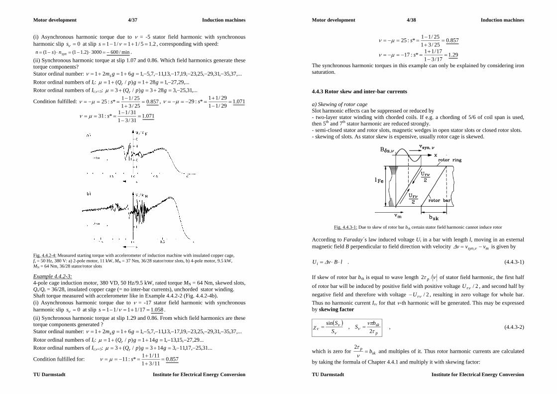
Motor development 4/37 Induction machines
TU Darmstadt Institute for Electrical Energy Conversion
(i) Asynchronous harmonic torque due to = -5 stator field harmonic with synchronous harmonic slip 0s at slip 2.15/11/11 s , corresponding with speed: min/6003000)2.11()1( synnsn . (ii) Synchronous harmonic torque at slip 1.07 and 0.86. Which field harmonics generate these torque components? Stator ordinal number: ,...37,35,31,29,25,23,19,17,13,11,7,5,16121 ggms Rotor ordinal numbers of Ir: ,...29,27,1281)/(1 ggpQr Rotor ordinal numbers of Ir,=3: ,...31,25,3283)/(3 ggpQr
Condition fulfilled: 857.025/3125/11*:25
s , 071.129/1129/11*:29
s
071.131/3131/11*:31
s
Fig. 4.4.2-4: Measured starting torque with accelerometer of induction machine with insulated copper cage, fs = 50 Hz, 380 V: a) 2-pole motor, 11 kW, MN = 37 Nm, 36/28 stator/rotor slots, b) 4-pole motor, 9.5 kW, MN = 64 Nm, 36/28 stator/rotor slots Example 4.4.2-3: 4-pole cage induction motor, 380 VD, 50 Hz/9.5 kW, rated torque MN = 64 Nm, skewed slots, Qs/Qr = 36/28, insulated copper cage (= no inter-bar currents), unchorded stator winding. Shaft torque measured with accelerometer like in Example 4.4.2-2 (Fig. 4.4.2-4b). (i) Asynchronous harmonic torque due to = -17 stator field harmonic with synchronous harmonic slip 0s at slip 058.117/11/11 s . (ii) Synchronous harmonic torque at slip 1.29 and 0.86. From which field harmonics are these torque components generated ? Stator ordinal number: ,...37,35,31,29,25,23,19,17,13,11,7,5,16121 ggms Rotor ordinal numbers of Ir: ...29,27,15,13,1141)/(1 ggpQr Rotor ordinal numbers of Ir,=3: ...31,25,17,11,3143)/(3 ggpQr
Condition fulfilled for: 857.011/3111/11*:11
s
Motor development 4/38 Induction machines
TU Darmstadt Institute for Electrical Energy Conversion
857.025/3125/11*:25
s
29.117/3117/11*:17
s
The synchronous harmonic torques in this example can only be explained by considering iron saturation. 4.4.3 Rotor skew and inter-bar currents a) Skewing of rotor cage Slot harmonic effects can be suppressed or reduced by - two-layer stator winding with chorded coils. If e.g. a chording of 5/6 of coil span is used, then 5th and 7th stator harmonic are reduced strongly. - semi-closed stator and rotor slots, magnetic wedges in open stator slots or closed rotor slots. - skewing of slots. As stator skew is expensive, usually rotor cage is skewed.
Fig. 4.4.3-1: Due to skew of rotor bar bsk certain stator field harmonic cannot induce rotor According to Faraday´s law induced voltage Ui in a bar with length l, moving in an external magnetic field B perpendicular to field direction with velocity msyn vvv , is given by
lBvUi . (4.4.3-1) If skew of rotor bar bsk is equal to wave length /2 p of stator field harmonic, the first half of rotor bar will be induced by positive field with positive voltage 2/rU , and second half by negative field and therefore with voltage 2/rU , resulting in zero voltage for whole bar. Thus no harmonic current Ir for that -th harmonic will be generated. This may be expressed by skewing factor
p
skbS
SS
2
,sin
, (4.4.3-2)
which is zero for skp b
2
and multiples of it. Thus rotor harmonic currents are calculated
by taking the formula of Chapter 4.4.1 and multiply it with skewing factor:

Motor development 4/39 Induction machines
TU Darmstadt Institute for Electrical Energy Conversion
srhrsr
rhsrwsssr I
LLjsRLQkNmjI
)(/)/2( (4.4.3-3)
Conclusions: If the rotor cage is skewed by one stator slot pitch sskb , then all stator slot harmonics will induce the rotor only negligibly. Example 4.4.3-1: 4-pole induction motor with 36/28 stator/rotor slots. Rotor cage skewed by one stator slot pitch: 9/pskb Stator field harmonics: Ordinal numbers: ,...37,35,31,29,25,23,19,17,13,11,7,5,161 g
Slot harmonics: ,...37,35,19,17,1)2/36(1 g
1 -17 19 -35 37 0.9949 0.0585 -0.0523 -0.0284 0.0267
Table 4.4.3-1: Skewing factor for stator slot harmonics, if rotor cage is skewed by one stator slot
Fig. 4.4.3-2: Skewing of rotor bars bsk leads also to skew of rotor field harmonics, excited by rotor current Ir. So phase shift between stator and rotor field harmonic varies along bar length and leads to cancelling of synchronous slot harmonic torque. Harmonic synchronous torque is also reduced strongly by skewing. The rotor field harmonics of the rotor field, excited by rotor current, are – as explained – all of slot harmonic order. If rotor is skewed by one stator slot pitch, also the rotor slot harmonic flux waves are skewed in the same way (Fig. 4.4.3-2). For stator slot harmonics therefore phase shift angle varies between –180° ... 180° along rotor bar length. Average harmonic torque production is therefore zero.
Motor development 4/40 Induction machines
TU Darmstadt Institute for Electrical Energy Conversion
0sin~180
180
dIIM rse (4.4.3-4)
Conclusions: Skewing by one stator slot pitch leaves the fundamental field almost unaffected, but nearly cancels the inducing effect of stator slot harmonics. Therefore asynchronous harmonic torque components due to stator slot harmonics are minimized effectively. Skewing generates also variable phase shift between stator and rotor field wave, thus allowing cancelling of synchronous harmonic torque. In order to avoid distortion of fundamental asynchronous torque M(n)-characteristic by harmonic torque effect, cage rotors of line-starting induction machines are always skewed, usually by one stator slot pitch. b) Losses due to inter-bar currents: Rotor bars are usually not insulated, but have electrical contact to iron stack. As number of turns per winding (= per bar) is only 1/2, induced voltage is low, so no big voltage difference between cage and iron occurs. Along rotor circumference induced voltage varies sinusoidal, so total rotor potential as average value of voltage sinus distribution is zero. Moreover, only with copper bars, inserted manually in rotor slots, cage insulation is possible, whereas with aluminium die cast cage usually not. By the way, between iron stack and copper or aluminium bar, oxidation of iron will cause additional contact resistance, which can be measured as inter-bar resistance Rq between adjacent bars according to Fig. 4.4.3-3. So by nature itself, rotor bars are insulated to a certain extent. If A denotes the half-surface of a rotor bar, the inter-bar resistance is smaller, if A is bigger.
AlR
ox
oxq (4.4.3-5)
Neglecting the good conducting iron and copper or aluminium part, inter-bar resistance is determined by thickness of oxidation layer lox between bar and iron and conductivity of this oxide ox. A typical value for aluminium die cast cages is
2610/ mlr oxoxq , (4.4.3-6) from which inter-bar resistance is calculated by ArR qq / .
Fig. 4.4.3-3: Inter-bar resistance between adjacent bars Rq is much bigger than bar or ring resistance, as it is determined by oxidation of iron stack and bar surface. a) Inter-bar current flow via half bar-surface A during operation, b) During measurement current flows via 2A, hence we obtain: Rq = 2(U/I – Rbar - Rring).
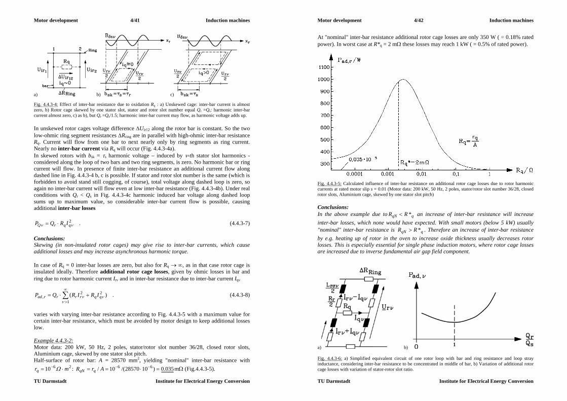
Motor development 4/41 Induction machines
TU Darmstadt Institute for Electrical Energy Conversion
a) b) c) Fig. 4.4.3-4: Effect of inter-bar resistance due to oxidation Rq : a) Unskewed cage: inter-bar current is almost zero, b) Rotor cage skewed by one stator slot, stator and rotor slot number equal Qr =Qs: harmonic inter-bar current almost zero, c) as b), but Qr =Qs/1.5; harmonic inter-bar current may flow, as harmonic voltage adds up. In unskewed rotor cages voltage difference Uir12 along the rotor bar is constant. So the two low-ohmic ring segment resistances Rring are in parallel with high-ohmic inter-bar resistance Rq. Current will flow from one bar to next nearly only by ring segments as ring current. Nearly no inter-bar current via Rq will occur (Fig. 4.4.3-4a). In skewed rotors with bsk = s harmonic voltage – induced by -th stator slot harmonics - considered along the loop of two bars and two ring segments, is zero. No harmonic bar or ring current will flow. In presence of finite inter-bar resistance an additional current flow along dashed line in Fig. 4.4.3-4 b, c is possible. If stator and rotor slot number is the same (which is forbidden to avoid stand still cogging, of course), total voltage along dashed loop is zero, so again no inter-bar current will flow even at low inter-bar resistance (Fig. 4.4.3-4b). Under real conditions with Qr < Qs in Fig. 4.4.3-4c harmonic induced bar voltage along dashed loop sums up to maximum value, so considerable inter-bar current flow is possible, causing additional inter-bar losses
2 qqrQ IRQP . (4.4.3-7)
Conclusions: Skewing (in non-insulated rotor cages) may give rise to inter-bar currents, which cause additional losses and may increase asynchronous harmonic torque. In case of Rq = 0 inter-bar losses are zero, but also for Rq , as in that case rotor cage is insulated ideally. Therefore additional rotor cage losses, given by ohmic losses in bar and ring due to rotor harmonic current Ir and in inter-bar resistance due to inter-bar current Iq
1
22, )(
qqrrrrad IRIRQP . (4.4.3-8)
varies with varying inter-bar resistance according to Fig. 4.4.3-5 with a maximum value for certain inter-bar resistance, which must be avoided by motor design to keep additional losses low. Example 4.4.3-2: Motor data: 200 kW, 50 Hz, 2 poles, stator/rotor slot number 36/28, closed rotor slots, Aluminium cage, skewed by one stator slot pitch. Half-surface of rotor bar: A = 28570 mm2, yielding "nominal" inter-bar resistance with
2610 mrq : 035.0)1028570/(10/ 66 ArR qqN m (Fig.4.4.3-5).
Motor development 4/42 Induction machines
TU Darmstadt Institute for Electrical Energy Conversion
At "nominal" inter-bar resistance additional rotor cage losses are only 350 W ( = 0.18% rated power). In worst case at R*q = 2 m these losses may reach 1 kW ( = 0.5% of rated power).
Fig. 4.4.3-5: Calculated influence of inter-bar resistance on additional rotor cage losses due to rotor harmonic currents at rated motor slip s = 0.01 (Motor data: 200 kW, 50 Hz, 2 poles, stator/rotor slot number 36/28, closed rotor slots, Aluminium cage, skewed by one stator slot pitch) Conclusions: In the above example due to qqN RR * an increase of inter-bar resistance will increase inter-bar losses, which none would have expected. With small motors (below 5 kW) usually "nominal" inter-bar resistance is qqN RR * . Therefore an increase of inter-bar resistance by e.g. heating up of rotor in the oven to increase oxide thickness usually decreases rotor losses. This is especially essential for single phase induction motors, where rotor cage losses are increased due to inverse fundamental air gap field component.
a) b) Fig. 4.4.3-6: a) Simplified equivalent circuit of one rotor loop with bar and ring resistance and loop stray inductance, considering inter-bar resistance to be concentrated in middle of bar, b) Variation of additional rotor cage losses with variation of stator-rotor slot ratio.

Motor development 4/43 Induction machines
TU Darmstadt Institute for Electrical Energy Conversion
Qs = Qr : Unskewed rotors have nearly no inter-bar losses (Fig. 4.4.3-4a). With skewed rotors, inter-bar losses vary also with ratio Qr/Qs. At Qr/Qs = 1 these losses are minimum (Fig. 4.4.3-4b). Qs > Qr : The rather low rotor slot number causes a big deviation of step-like rotor flux density distribution, excited by Ir, from sine wave fundamental, thus rrhr LLL 1/1 is rather big and limits rotor harmonic and inter-bar current (Fig. 4.4.3-6a). Qs < Qr : High rotor slot number yields causes a smaller deviation of step-like rotor flux density distribution, excited by Ir, from sine wave fundamental, so factor is closer to unity, Lr is small and harmonic currents and related losses will increase (Fig. 4.4.3-6b). Conclusions: Line-starting cage induction motors have skewed rotor cage to reduce harmonic torque influence on start-up torque. Rotor slot number is chosen SMALLER than stator slot number to reduce additional inter-bar losses. Example 4.4.3-3: Explosion proof induction motor (EExeII): Data: Motor size 80 mm, pole number 2p = 2, slot numbers Qs / Qr = 18 / 23, Qs < Qr (!), rotor skewed by one rotor slot pitch. Motor was operated on test-bench at rated load. Rotor cage temperature was too high due to increased inter-bar losses, also heating up stator winding too much. After changing rotor against a new one with Qr = 14 (skewed), Qs > Qr (!) with the same bar and ring resistance losses went down significantly, so that stator winding temperature stayed within thermal limits. c) Additional asynchronous harmonic torque due to inter-bar currents: Considering simplified equivalent circuit Fig. 4.4.3-6 a), one can solve this mesh equation, getting the inter-bar current Iq per harmonic induced rotor voltage Ur. So in rotor bars flows the superposition of Ir (valid for infinite Rq) and of Iq . For unskewed cage induced voltage in upper and lower mesh half is simply Ur/2, so Iq in this simplified equivalent circuit is exactly zero. For skewed cage one gets inter-bar current Iq flow, so the bar harmonic currents Ir Iq generate not only the harmonic asynchronous torque due to Ir , as explained in Chapter 4.4.2,
2222
,
22
))(()()2(
s
rhrsr
r
synr
rhswssse I
LLsRRs
QLkNmM (4.4.3-9)
but also an additional harmonic torque due to Iq
2222
,
22
))(()4(
)4()()2(
qsrhrsqr
qr
synr
rhswssseq I
LLsRR
RRsQ
LkNmM
, (4.4.3-10)
depending on factor q instead of .
p
skq
bS
SS
22/
2/sin 2 . (4.4.3-11)
Motor development 4/44 Induction machines
TU Darmstadt Institute for Electrical Energy Conversion
Break down slip, where maximum harmonic torque occurs, is much bigger for Meq than for Me (Fig. 4.4.3-7):
)(4
rhrs
qrb LL
RRs
instead of
)( rhrs
rb LL
Rs
. (4.4.3-12)
Fig. 4.4.3-7: Qualitative characteristic of asynchronous harmonic torque Me (at infinite inter-bar resistance) and additional torque Meq due to inter-bar current with its much bigger break-down slip Example 4.4.3-4: With rotor cage skewed by one stator slot pitch, skewing factor is almost zero, so asynchronous harmonic torques disappear. But on the other hand factor q differs from zero for first / third / fifth ... pair of slot harmonics, so additional asynchronous torque Meq appear. Motor data: 4-pole induction motor with 36/28 stator/rotor slots. Rotor cage skewed by one stator slot pitch: 9/pskb Stator slot harmonics: ,...37,35,19,17,1)2/36(1 g
1 -17 19 -35 37 0.9949 0.0585 -0.0523 -0.0284 0.0267 q 0.0871 -0.669 0.598 -0.0025 0.0024
Table 4.4.3-2: Skewing factor and influence of inter-bar resistance for stator slot harmonics, if rotor cage is skewed by one stator slot
Fig. 4.4.3-8: Qualitative characteristic of total asynchronous torque as superposition of the fundamental and of the harmonic torque Meq (here: 5th and 7th harmonic) due to inter-bar currents
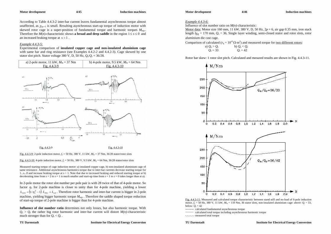
Motor development 4/45 Induction machines
TU Darmstadt Institute for Electrical Energy Conversion
According to Table 4.4.3-2 inter-bar current leaves fundamental asynchronous torque almost unaffected, as q=1 is small. Resulting asynchronous start-up torque of induction motor with skewed rotor cage is a super-position of fundamental torque and harmonic torques Meq. Therefore the M(n)-characteristic shows a broad and deep saddle in the region 01 s and an increased braking torque at 1s . Example 4.4.3-5: Experimental comparison of insulated copper cage and non-insulated aluminium cage with same bar and ring resistance (see Examples 4.4.2-2 and 4.4.2-3). Cage skewed by one stator slot pitch. Stator voltage 380 V, D, 50 Hz, Qs/Qr = 36/28.
a) 2-pole motor, 11 kW, MN = 37 Nm Fig. 4.4.3-9
b) 4-pole motor, 9.5 kW, MN = 64 Nm Fig. 4.4.3-10
Fig. 4.4.3-9 Fig. 4.4.3-10 Fig. 4.4.3-9: 2-pole induction motor, fs = 50 Hz, 380 V, 11 kW, MN = 37 Nm, 36/28 stator/rotor slots Fig. 4.4.3-10: 4-pole induction motor, fs = 50 Hz, 380 V, 9.5 kW, MN = 64 Nm, 36/28 stator/rotor slots Measured starting torque of cage induction motor: a) insulated copper cage, b) non-insulated aluminium cage of same resistance. Additional asynchronous harmonics torque due to inter-bar currents decrease starting torque for 1...s...0 and increase braking torque at s > 1. Note that due to increased braking and reduced starting torque at b) decelerating time from s = 2 to s = 1 is much smaller and start-up time from s = 1 to s = 0 takes longer than at a). In 2-pole motor the rotor slot number per pole pair is with 28 twice of that of 4-pole motor. So factor for 2-pole machine is closer to unity than for 4-pole machine, yielding a lower
rrhr LLL 1/1 2 . Therefore rotor harmonic and inter-bar current is bigger in 2-pole machine, yielding bigger harmonic torque Meq . Therefore the saddle shaped torque reduction of start-up torque of 2-pole machine is bigger than for 4-pole machine. Influence of slot number ratio determines not only losses, but also harmonic torque. With Qs > Qr the rather big rotor harmonic and inter-bar current will distort M(n)-characteristic much stronger than for Qs < Qr .
Motor development 4/46 Induction machines
TU Darmstadt Institute for Electrical Energy Conversion
Example 4.4.3-6: Influence of slot number ratio on M(n)-characteristic: Motor data: Motor size 160 mm, 11 kW, 380 V, D, 50 Hz, 2p = 6, air gap 0.35 mm, iron stack length lFe = 170 mm, Qs = 36, Single layer winding, semi-closed stator and rotor slots, rotor aluminium die cast cage. Comparison of calculated (rq = 10-6 .m2) and measured torque for two different rotors: a) Qs > Qr b) Qs < Qr Qr = 33 Qr = 42 Rotor bar skew: 1 rotor slot pitch. Calculated and mesured results are shown in Fig. 4.4.3-11.
Fig. 4.4.3-11: Measured and calculated torque characteristic between stand still and no-load of 6-pole induction motor, fs = 50 Hz, 380 V, 11 kW, MN = 110 Nm, 36 stator slots, non-insulated aluminium cage: above: Qr = 33, below: Qr = 42 --------- calculated fundamental asynchronous torque _________ calculated total torque including asynchronous harmonic torque -.-.-.-.-.- measured total torque
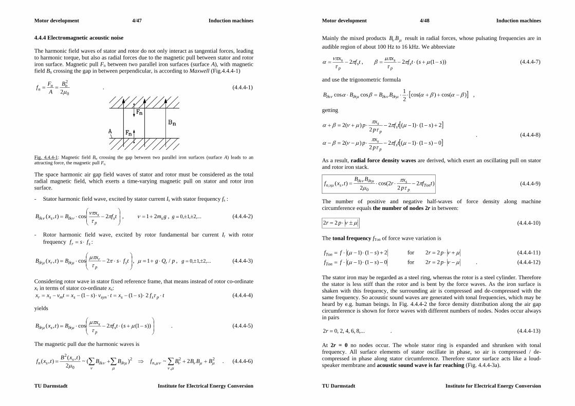
Motor development 4/47 Induction machines
TU Darmstadt Institute for Electrical Energy Conversion
4.4.4 Electromagnetic acoustic noise The harmonic field waves of stator and rotor do not only interact as tangential forces, leading to harmonic torque, but also as radial forces due to the magnetic pull between stator and rotor iron surface. Magnetic pull Fn between two parallel iron surfaces (surface A), with magnetic field Bn crossing the gap in between perpendicular, is according to Maxwell (Fig.4.4.4-1)
0
2
2nn
nB
AFf . (4.4.4-1)
Fig. 4.4.4-1: Magnetic field Bn crossing the gap between two parallel iron surfaces (surface A) leads to an attracting force, the magnetic pull Fn The space harmonic air gap field waves of stator and rotor must be considered as the total radial magnetic field, which exerts a time-varying magnetic pull on stator and rotor iron surface. - Stator harmonic field wave, excited by stator current Is with stator frequency fs :
tfxBtxB s
p
ssss
2cos),( , gms21 , ,...2,1,0 g (4.4.4-2)
- Rotor harmonic field wave, excited by rotor fundamental bar current Ir with rotor
frequency sr fsf :
tfsxBtxB s
p
rrrr
2cos),( , pQg r /1 , ,...2,1,0 g (4.4.4-3)
Considering rotor wave in stator fixed reference frame, that means instead of rotor co-ordinate xr in terms of stator co-ordinate xs:
tfsxtvsxtvxx psssynsmsr 2)1()1( (4.4.4-4) yields
))1((2cos),( sstfxBtxB s
p
srsr
. (4.4.4-5)
The magnetic pull due the harmonic waves is
,
22,
2
0
22~)(~
2),(),( BBBBfBBtxBtxf nrs
ssn . (4.4.4-6)
Motor development 4/48 Induction machines
TU Darmstadt Institute for Electrical Energy Conversion
Mainly the mixed products BB result in radial forces, whose pulsating frequencies are in audible region of about 100 Hz to 16 kHz. We abbreviate
tfxs
p
s 2 , ))1((2 sstfx
sp
s (4.4.4-7)
and use the trigonometric formula
)cos()cos(21coscos rsrs BBBB ,
getting
0)1()1(22
)(2
2)1()1(22
)(2
stfpxp
stfpxp
sp
s
sp
s
. (4.4.4-8)
As a result, radial force density waves are derived, which exert an oscillating pull on stator and rotor iron stack.
)22
2cos(2
),(0
, tfpxr
BBtxf Ton
p
srssn
(4.4.4-9)
The number of positive and negative half-waves of force density along machine circumference equals the number of nodes 2r in between:
pr 22 (4.4.4-10) The tonal frequency fTon of force wave variation is
2)1()1( sffTon for pr 22 (4.4.4-11)
0)1()1( sffTon for pr 22 . (4.4.4-12) The stator iron may be regarded as a steel ring, whereas the rotor is a steel cylinder. Therefore the stator is less stiff than the rotor and is bent by the force waves. As the iron surface is shaken with this frequency, the surrounding air is compressed and de-compressed with the same frequency. So acoustic sound waves are generated with tonal frequencies, which may be heard by e.g. human beings. In Fig. 4.4.4-2 the force density distribution along the air gap circumference is shown for force waves with different numbers of nodes. Nodes occur always in pairs
,...8,6,4,2,02 r . (4.4.4-13) At 2r = 0 no nodes occur. The whole stator ring is expanded and shrunken with tonal frequency. All surface elements of stator oscillate in phase, so air is compressed / de-compressed in phase along stator circumference. Therefore stator surface acts like a loud-speaker membrane and acoustic sound wave is far reaching (Fig. 4.4.4-3a).
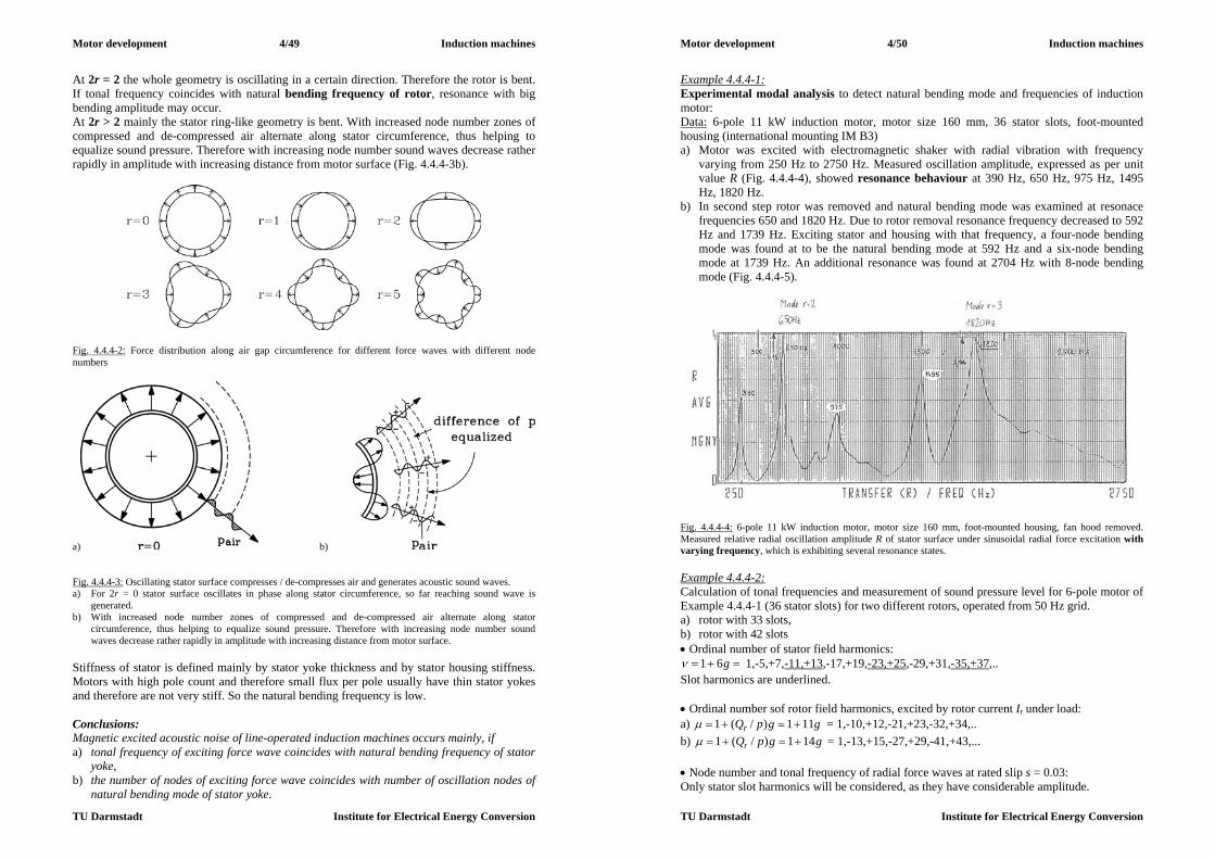
Motor development 4/49 Induction machines
TU Darmstadt Institute for Electrical Energy Conversion
At 2r = 2 the whole geometry is oscillating in a certain direction. Therefore the rotor is bent. If tonal frequency coincides with natural bending frequency of rotor, resonance with big bending amplitude may occur. At 2r > 2 mainly the stator ring-like geometry is bent. With increased node number zones of compressed and de-compressed air alternate along stator circumference, thus helping to equalize sound pressure. Therefore with increasing node number sound waves decrease rather rapidly in amplitude with increasing distance from motor surface (Fig. 4.4.4-3b).
Fig. 4.4.4-2: Force distribution along air gap circumference for different force waves with different node numbers
a) b) Fig. 4.4.4-3: Oscillating stator surface compresses / de-compresses air and generates acoustic sound waves. a) For 2r = 0 stator surface oscillates in phase along stator circumference, so far reaching sound wave is
generated. b) With increased node number zones of compressed and de-compressed air alternate along stator
circumference, thus helping to equalize sound pressure. Therefore with increasing node number sound waves decrease rather rapidly in amplitude with increasing distance from motor surface.
Stiffness of stator is defined mainly by stator yoke thickness and by stator housing stiffness. Motors with high pole count and therefore small flux per pole usually have thin stator yokes and therefore are not very stiff. So the natural bending frequency is low. Conclusions: Magnetic excited acoustic noise of line-operated induction machines occurs mainly, if a) tonal frequency of exciting force wave coincides with natural bending frequency of stator
yoke, b) the number of nodes of exciting force wave coincides with number of oscillation nodes of
natural bending mode of stator yoke.
Motor development 4/50 Induction machines
TU Darmstadt Institute for Electrical Energy Conversion
Example 4.4.4-1: Experimental modal analysis to detect natural bending mode and frequencies of induction motor: Data: 6-pole 11 kW induction motor, motor size 160 mm, 36 stator slots, foot-mounted housing (international mounting IM B3) a) Motor was excited with electromagnetic shaker with radial vibration with frequency
varying from 250 Hz to 2750 Hz. Measured oscillation amplitude, expressed as per unit value R (Fig. 4.4.4-4), showed resonance behaviour at 390 Hz, 650 Hz, 975 Hz, 1495 Hz, 1820 Hz.
b) In second step rotor was removed and natural bending mode was examined at resonace frequencies 650 and 1820 Hz. Due to rotor removal resonance frequency decreased to 592 Hz and 1739 Hz. Exciting stator and housing with that frequency, a four-node bending mode was found at to be the natural bending mode at 592 Hz and a six-node bending mode at 1739 Hz. An additional resonance was found at 2704 Hz with 8-node bending mode (Fig. 4.4.4-5).
Fig. 4.4.4-4: 6-pole 11 kW induction motor, motor size 160 mm, foot-mounted housing, fan hood removed. Measured relative radial oscillation amplitude R of stator surface under sinusoidal radial force excitation with varying frequency, which is exhibiting several resonance states. Example 4.4.4-2: Calculation of tonal frequencies and measurement of sound pressure level for 6-pole motor of Example 4.4.4-1 (36 stator slots) for two different rotors, operated from 50 Hz grid. a) rotor with 33 slots, b) rotor with 42 slots Ordinal number of stator field harmonics:
g61 1,-5,+7,-11,+13,-17,+19,-23,+25,-29,+31,-35,+37,.. Slot harmonics are underlined. Ordinal number sof rotor field harmonics, excited by rotor current Ir under load: a) ggpQr 111)/(1 = 1,-10,+12,-21,+23,-32,+34,.. b) ggpQr 141)/(1 = 1,-13,+15,-27,+29,-41,+43,... Node number and tonal frequency of radial force waves at rated slip s = 0.03: Only stator slot harmonics will be considered, as they have considerable amplitude.

Motor development 4/51 Induction machines
TU Darmstadt Institute for Electrical Energy Conversion
a) b) Fig. 4.4.4-5: 6-pole 11 kW induction motor, stator iron stack and housing, rotor removed (data see Fig. 4.4.4-4). Measured relative radial oscillation amplitude R of stator surface under sinusoidal radial force excitation at fixed excitation frequency to investigate natural bending modes., resulting in a) at excitation frequency: 592 Hz and 604 Hz, four-node bending mode as natural bending mode b) at excitation frequency: 1739 Hz: 6-node bending mode
2704 Hz: 8-node bending mode
Fig. 4.4.4-6: Measured sound pressure level of 6-pole 11 kW induction motor at rated load, removed fan hood, operated at 50 Hz (--------) and 60 Hz (___________) alternatively. Maximum sound pressure occurs in 500 Hz and 2000 Hz band with up to 78 dB(A). Graphs shows sound pressure level at loudest point ( = aside of motor in 1 m distance of motor surface). Rotor a): = -11, µ = -10: 3)1011(3)( pr , 5.5330)03.01)(110(50 Tonf Hz
= 13, µ = 12 : 3)1213(3)( pr , 5.5330)03.01)(112(50 Tonf Hz
= -23, µ = 23 : 0)2323(3)( pr , 11672)03.01)(123(50 Tonf Hz
= -35, µ = 34 : 3)3435(3)( pr , 5.17002)03.01)(134(50 Tonf Hz
Motor development 4/52 Induction machines
TU Darmstadt Institute for Electrical Energy Conversion
From modal analysis natural bending modes and frequencies are known: r = 2, f = 592Hz; r = 3, f = 1739 Hz. Therefore oscillation with 533.5 Hz and 1700.5 Hz is amplified. Measured sound pressure level LpA was frequency analysed within frequency bands (Fig. 4.4.4-6). Frequency band centred at 500 Hz and that centred at 2000 Hz showed sound pressure level up to 78 dB(A), which for a 11 kW motor is already rather noisy. These noise peaks are due to the resonance at 592 Hz and 1739 Hz, which are excited by the force waves 533.5 Hz and 1700.5 Hz. Operation of motor at 60 Hz grid yields a 120% shift in exciting frequency. So also measured acoustic sound spectrum is shifted by that 120% to higher frequencies (Fig. 4.4.4-6). Rotor b): = 13, µ = -13: 0)1313(3)( pr , 5.5792)03.01)(113(50 Tonf Hz
= -29, µ = 29 : 0)2929(3)( pr , 14582)03.01)(129(50 Tonf Hz With rotor b) the exciting vibration modes differ considerably from the natural vibration modes (r = 0 instead of r = 2 or 3). Thus no resonance excitation occurs. Measured sound pressure level is much lower: the dominating value occurs in the 500 Hz band with only 62dB(A)). Conclusions: In that example the same stator delivers a much lower magnetic acoustic sound with rotor b) instead of rotor a). So the stator-rotor slot combination and mechanical resonance determine mainly magnetic acoustic performance. Please note, that the same motor was already treated in Example 4.4.3-6. The low noise motor with slot combination 36/42 delivered a rather bad M(n)-curve due to inter-bar currents. So to develop an overall good motor, it is necessary to consider all different motor attributes such as thermal performance, starting torque, overload capability, noise. For this motor it would be necessary to use a chorded two-layer winding (which is more expensive than an unchorded single layer winding) to reduce 5th and 7th stator field harmonic in the 36/42 slot combination to get a satisfying M(n)-curve.

Motor development 5/1 Inverter-fed induction machines
TU Darmstadt Institute for Electrical Energy Conversion
5. Inverter-fed induction machines 5.1 Basic performance of variable-speed induction machines Induction machines operate at fixed stator frequency between no-load (synchronous speed) and rated slip, so speed differs only a few percent ("fixed speed drive"). Cage induction machine with continuously varying speed is possible with frequency inverter, which generates a three-phase voltage system with variable frequency, which yields variable synchronous speed and therefore variable speed induction machine. Most inverters are voltage-source inverters with DC voltage link. (Current source inverters with a big choke in the DC current link are used only for bigger power and are nowadays rather rare in use). Grid input with its fixed frequency and voltage is rectified and smoothened by a DC link capacitor. Most of the smaller inverters operate with diode rectifier, getting as DC link voltage
LLd UU 2)/3( (5.1-1) Example 5.1-1: 400 V grid, 5404002)/3( dU V From this DC link voltage a new variable frequency voltage system is generated by pulse width modulation (PWM). Output line-to-line voltage is a series of pulses of dU or dU , which may be Fourier-analyzed.
1, )cos(ˆ)(
kskLLLL tkUtu (5.1-2)
Fourier fundamental line-to-line sinus voltage 1,
ˆkLLU and its corresponding phase voltage
3/ˆˆ1,1, kLLks UU (if motor stator winding is star-connected) is the necessary input for
variable speed motor operation. Higher time harmonics 1,ˆ
kLLU cause additional motor current with higher frequency fsk = k.fs , which cause additional losses, pulsating torque and generate audible magnetic noise. Neglecting these parasitic effects, variable speed motor operation is determined by variable 2/ˆ
1, kss UU and variable fs. a) Influence of stator resistance Rs neglected: Stator voltage equation yields
2/)( ssrshsssss jIILjILjU , (5.1-3) so constant flux linkage in the machine at variable frequency is only possible for voltage change proportional to frequency:
ss fU ~ (5.1-4) Torque-speed characteristic for Rs = 0 is Kloss function, which can also be expressed in terms of rotor frequency sr fsf :
Motor development 5/2 Inverter-fed induction machines
TU Darmstadt Institute for Electrical Energy Conversion
b
r
r
b
b
bb
es
ss
ssM
MR
22:0 (5.1-5)
Breakdown torque Mb occurs at rotor breakdown frequency
r
rs
r
rb L
RXR
´ (+: motor, -: generator) , (5.1-6)
which is independent of stator frequency. Note that also breakdown torque is independent of stator frequency, if ss fU ~ . With 2/sssU we get
ss
s
ss
s
sbs L
pmX
UpmMR
1
221
2:0 22 (+: motor, -: generator) . (5.1-7)
Therefore variable stator frequency means shifting of torque-speed characteristic parallel to abscissa with unchanged shape of characteristic (Fig. 5.1-1). Motor operation range is always for each of these characteristics between br 0 , if maximum torque (breakdown torque) with its overload current is possible due to sufficient inverter current limit.
Fig. 5.1-1: Inverter operated induction motor, stator resistance neglected, only voltage fundamental of PWM inverter output voltage pattern considered: Parallel shift of torque-speed characteristic with variable stator frequency fs and Us /fs = const. With rising frequency fs stator voltage must rise, too. By broadening the voltage impulses and narrowing the voltage gaps (zero voltage) in between, the fundamental amplitude increases. Thus the modulation degree
dkLL UUm /ˆ)3/2( 1, (5.1-8) rises with increased frequency up to unity, where usually rated frequency is defined: fs = fN. If m > 1 (over-modulation), maximum inverter output voltage is reached, if the voltage pulses
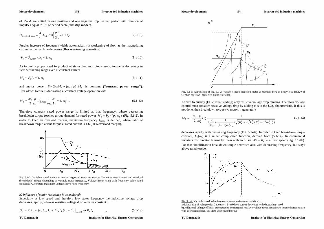
Motor development 5/3 Inverter-fed induction machines
TU Darmstadt Institute for Electrical Energy Conversion
of PWM are united in one positive and one negative impulse per period with duration of impulses equal to 1/3 of period each ("six step mode").
ddkLL UUU 1.13
sin4ˆmax,1,
(5.1-9)
Further increase of frequency yields automatically a weakening of flux, as the magnetizing current in the machine decreases (flux weakening operation): ssss U /1~/ˆ
max, (5.1-10) As torque is proportional to product of stator flux and rotor current, torque is decreasing in field weakening range even at constant current.
srse IM /1~~ (5.1-11) and motor power ese MpnMP )/(2 is constant ("constant power range"). Breakdown torque is decreasing at constant voltage operation with
22max, /1~1
2 sss
ss
sb L
UpmM
. (5.1-12)
Therefore constant rated power range is limited at that frequency, where decreasing breakdown torque reaches torque demand for rated power )/( sNe pPM (Fig. 5.1-2). In order to keep an overload margin, maximum frequency fs,max is defined, where ratio of breakdown torque versus torque at rated current is 1.6 (60% overload margin).
Fig. 5.1-2: Variable speed induction motor, neglected stator resistance: Torque at rated current and overload (breakdown) torque depending on variable stator frequency. Voltage linear rising with frequency below rated frequency fN, constant maximum voltage above rated frequency. b) Influence of stator resistance Rs considered: Especially at low speed and therefore low stator frequency the inductive voltage drop decreases rapidly, whereas resistive voltage drop remains constant:
ssrshsssssss IRIILjILjIRU 0)( , (5.1-13)
Motor development 5/4 Inverter-fed induction machines
TU Darmstadt Institute for Electrical Energy Conversion
Fig. 5.1-3: Application of Fig. 5.1-2: Variable speed induction motor as traction drive of heavy loco BR120 of German railways (neglected stator resistance) At zero frequency (DC current feeding) only resistive voltage drop remains. Therefore voltage control must consider resistive voltage drop by adding this to the Us/fs-characteristic. If this is not done, then breakdown torque (+: motor, -: generator)
))(()1(1
12 2222222
2
22
sssssssss
ss
s
sb
LRLRL
RUpmM
(5.1-14)
decreases rapidly with decreasing frequency (Fig. 5.1-4a). In order to keep breakdown torque constant, Us(s) is a rather complicated function, derived from (5.1-14). In commercial inverters this function is usually linear with an offset NsIRU at zero speed (Fig. 5.1-4b). For that simplification breakdown torque decreases also with decreasing frequency, but stays above rated torque.
Fig. 5.1-4: Variable speed induction motor, stator resistance considered: a) Linear rise of voltage with frequency : Breakdown torque decreases with decreasing speed b) Additional voltage offset at zero speed to compensate resistive voltage drop: Breakdown torque decreases also with decreasing speed, but stays above rated torque

Motor development 5/5 Inverter-fed induction machines
TU Darmstadt Institute for Electrical Energy Conversion
c) Drive technology: Inverter switches are usually insulated gate bipolar transistors (IGBT) with free wheeling diodes, operating at voltages between 200 V and 6000 V with switching frequencies up to 20 kHz for lower and up to about 500 Hz for higher voltage rating. For higher voltage and switching power gate turn off thyristors (GTO) and thyristors with auxiliary circuit to switch current off are in use at switching frequencies below 500 Hz. Below 200 V metal oxide silicon field effect transistors (MOSFET) are used as switches with switching frequencies up to 50 kHz. Induction motors may be operated at inverter supply without any speed sensor (voltage control). Speed is not constant ant constant stator frequency, but varies according to load and slip. At low frequency the short rotor time constant, which determines change of rotor flux, is rather small in comparison to voltage period T = 1/fs. Therefore rotor flux may be regarded as constant during one period, thus acting like a synchronous machine rotor. Therefore speed oscillations may occur, if load is changed, in the same way as it is the case for synchronous machines. If the rotor is equipped with a speed sensor, speed control – incorporated in the inverter - is possible, thus avoiding change of speed with slip and possible speed oscillations at low speed. Speed and underlying torque control allow the inverter-fed induction machine to operate as an adjustable speed drive with high dynamic performance, if a vector control algorithm is used for torque control. Depending on the power of the used microprocessor (e.g. 16 bit or 32 bit), elaborate digital control is possible. Using numerical motor models with observer-assisted control, even the speed sensor may be spared, calculating the actual speed from voltage and current measurement (speed sensorless control).
a) b) Fig. 5.1-5: Digital speed control of inverter-fed induction machine (Data see Example 5.1-2): Actual speed response to a) step-up of set-point speed, b) step-up and step-down in load torque Example 5.1-2: Speed controlled inverter-fed induction motor with speed sensor and digital vector control (1 ms cycle time for measuring and calculating) : Motor rated data: 400 V Y, 24 Nm, 1500/min, DC link voltage 600 V, inverter rated current 40 A, load inertia equal to motor inertia (each 0.011 kg.m2) Two examples of motor control: a) Step in speed set-point value nset for zero to 10/min: Actual speed nact in Fig. 5.1-5a is shown as calculated value from microprocessor. After about 4 ms actual speed reaches set-point speed for first time and with some overshoot and damped oscillation finally after 16 ms actual speed is constant 10/min.
Motor development 5/6 Inverter-fed induction machines
TU Darmstadt Institute for Electrical Energy Conversion
b) Load step from no-load to 10% of rated torque and back to no-load at set-point speed 1500/min: Actual speed (taken from speed sensor signal) dips at increased load and reaches set-point value again after 50 ms. At decreased load a speed over-shoot occurs for about 50 ms (Fig. 5.1-5b). 5.2 Drive characteristics of inverter-fed standard induction motors a) Thermal steady state performance: Standard motors are usually balanced for synchronous speed at 50 Hz, but are often capable of about running to twice frequency without additional measures, e.g. motor size 160 mm may be run up to 6000/min. Smaller motors may run with even elevated speed, bigger motors with less, as natural bending frequency of rotor decreases with increased motor size. Shaft mounted fan will produce increased air flow and noise at elevated speed, so often for higher speed operation fans with decreased diameter d are used. Rough estimate for change of sound pressure level of fans with speed and fan diameter is
)/lg(70)/lg(50 2121 ddnnLp (5.2-1) Example 5.2-1: Increase of fan sound pressure level at doubled speed: 15)2lg(50 pL dB Cooling air flow generated by fan rises linear with speed:
NsN ffnnV /~/~ (5.2-2) Iron losses in stator rise proportional to square of flux linkage, eddy current loss component with square and hysteresis loss component linear with frequency, so an average exponent x is assumed.
xNsNFe ffP )/()/(~ 2 , x 1.8 (5.2-3)
Friction losses due to bearings rise nearly linear with speed, but are usually much smaller than windage losses to due power consumption of shaft-mounted fan. Fan power consumption rises with cube of speed, so friction and windage losses rise with an exponent y = 2,5 ... 3.
yNs
yNwfr ffnnP )/(~)/(~ , y 2.5...3 (5.2-4)
Stray load losses (additional losses) due to space harmonic effects rise with speed and current:
21 )/()/(~ Ns
zNad IInnP , z 1.5...2 (5.2-5)
Considering the thermal power limit of the inverter-fed standard induction machine, we have to consider three frequency ranges (Fig. 5.2-1): :Ns ff Flux weakening range: Flux linkage decreases with sf/1~ , so iron losses are nearly constant. Motor is operated at rated current, so copper losses are constant. As motor is cooled better at high speed due to increased air flow, constant rated power operation is no
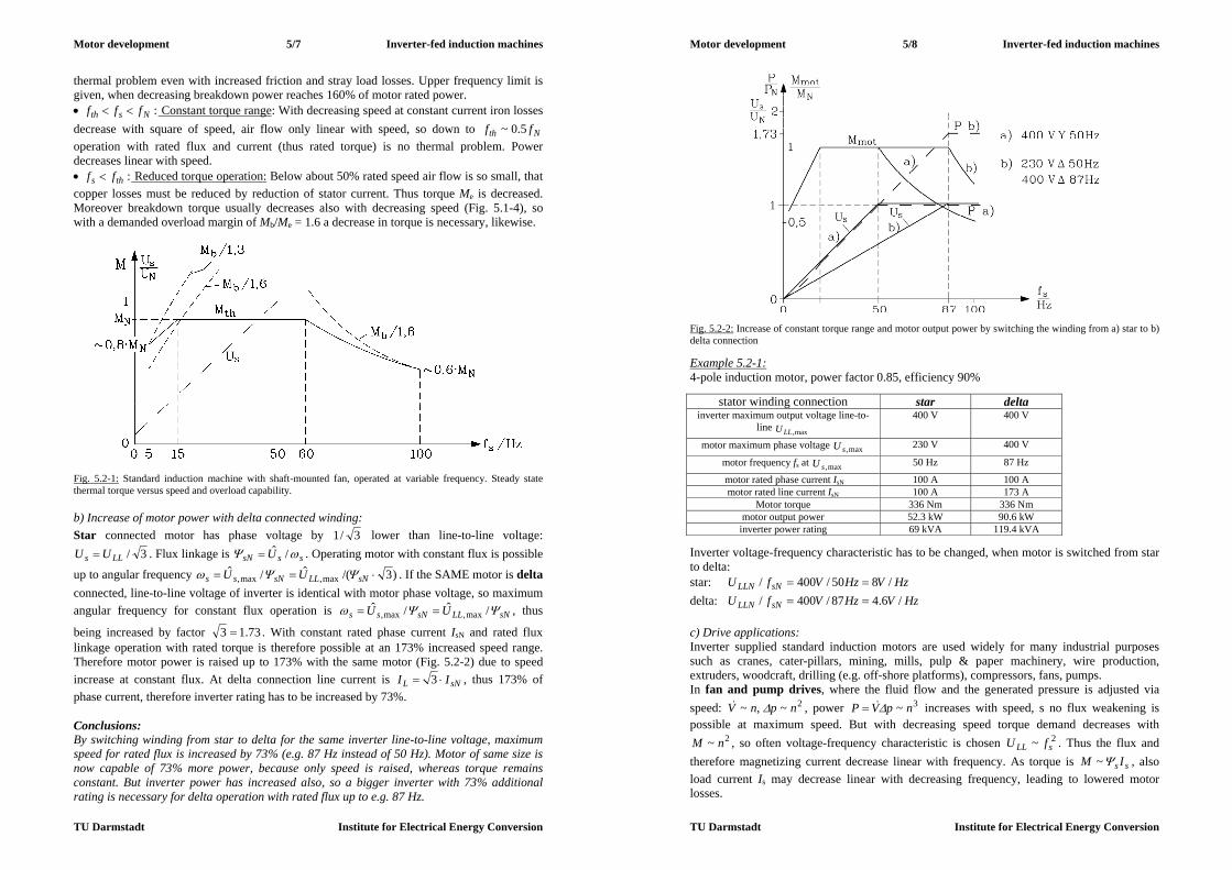
Motor development 5/7 Inverter-fed induction machines
TU Darmstadt Institute for Electrical Energy Conversion
thermal problem even with increased friction and stray load losses. Upper frequency limit is given, when decreasing breakdown power reaches 160% of motor rated power. :Nsth fff Constant torque range: With decreasing speed at constant current iron losses decrease with square of speed, air flow only linear with speed, so down to Nth ff 5.0~ operation with rated flux and current (thus rated torque) is no thermal problem. Power decreases linear with speed. :ths ff Reduced torque operation: Below about 50% rated speed air flow is so small, that copper losses must be reduced by reduction of stator current. Thus torque Me is decreased. Moreover breakdown torque usually decreases also with decreasing speed (Fig. 5.1-4), so with a demanded overload margin of Mb/Me = 1.6 a decrease in torque is necessary, likewise.
Fig. 5.2-1: Standard induction machine with shaft-mounted fan, operated at variable frequency. Steady state thermal torque versus speed and overload capability. b) Increase of motor power with delta connected winding: Star connected motor has phase voltage by 3/1 lower than line-to-line voltage:
3/LLs UU . Flux linkage is sssN U /ˆ . Operating motor with constant flux is possible
up to angular frequency )3/(ˆ/ˆmax,max, sNLLsNss UU . If the SAME motor is delta
connected, line-to-line voltage of inverter is identical with motor phase voltage, so maximum angular frequency for constant flux operation is sNLLsNss UU /ˆ/ˆ
max,max, , thus
being increased by factor 73.13 . With constant rated phase current IsN and rated flux linkage operation with rated torque is therefore possible at an 173% increased speed range. Therefore motor power is raised up to 173% with the same motor (Fig. 5.2-2) due to speed increase at constant flux. At delta connection line current is sNL II 3 , thus 173% of phase current, therefore inverter rating has to be increased by 73%. Conclusions: By switching winding from star to delta for the same inverter line-to-line voltage, maximum speed for rated flux is increased by 73% (e.g. 87 Hz instead of 50 Hz). Motor of same size is now capable of 73% more power, because only speed is raised, whereas torque remains constant. But inverter power has increased also, so a bigger inverter with 73% additional rating is necessary for delta operation with rated flux up to e.g. 87 Hz.
Motor development 5/8 Inverter-fed induction machines
TU Darmstadt Institute for Electrical Energy Conversion
Fig. 5.2-2: Increase of constant torque range and motor output power by switching the winding from a) star to b) delta connection Example 5.2-1: 4-pole induction motor, power factor 0.85, efficiency 90%
stator winding connection star delta inverter maximum output voltage line-to-
line max,LLU 400 V 400 V
motor maximum phase voltage max,sU 230 V 400 V
motor frequency fs at max,sU 50 Hz 87 Hz
motor rated phase current IsN 100 A 100 A motor rated line current IsN 100 A 173 A
Motor torque 336 Nm 336 Nm motor output power 52.3 kW 90.6 kW
inverter power rating 69 kVA 119.4 kVA Inverter voltage-frequency characteristic has to be changed, when motor is switched from star to delta: star: HzVHzVfU sNLLN /850/400/ delta: HzVHzVfU sNLLN /6.487/400/ c) Drive applications: Inverter supplied standard induction motors are used widely for many industrial purposes such as cranes, cater-pillars, mining, mills, pulp & paper machinery, wire production, extruders, woodcraft, drilling (e.g. off-shore platforms), compressors, fans, pumps. In fan and pump drives, where the fluid flow and the generated pressure is adjusted via speed: 2~,~ npnV , power 3~ npVP increases with speed, s no flux weakening is possible at maximum speed. But with decreasing speed torque demand decreases with
2~ nM , so often voltage-frequency characteristic is chosen 2~ sLL fU . Thus the flux and therefore magnetizing current decrease linear with frequency. As torque is ss IM ~ , also load current Is may decrease linear with decreasing frequency, leading to lowered motor losses.

Motor development 5/9 Inverter-fed induction machines
TU Darmstadt Institute for Electrical Energy Conversion
5.3 Features of special induction motors for inverter-operation a) Features of high-performance inverter-fed induction machines: High performance inverter-fed induction drives must be able to produce full torque also at stand-still for continuous duty, so an external fan, operating independent from motor speed, is necessary for cooling. A winding temperature sensor e.g. within winding overhang such as positive temperature coefficient sensor (PTC) is often used as thermal protection against overheating. Increased motor utilization is often necessary to get increased power out of a given volume such as for drives for tooling machinery or electric cars. If water-jacket cooling is chosen instead of indirect air cooling, stator winding heat transfer coefficient raises up to 300%. In that case losses may increase up to 300% for the same winding temperature. Motor power may be increased by 40%. Special attention is paid to low inertia and to overload capability (e.g. 180% for 4 min. in a 10 min. cycle, S6-40%) to get a drive with high dynamic performance. Low inertia is gained by low ratio Fesi ld / , but care must be taken not to get too low rotor natural bending frequency, it the rotor gets too "thin". High-performance motors are operated usually with a high resolution speed sensor for positioning purposes at low speed (e.g. 2048 increments per revolution), but must be capable also of high speed (e.g. motor size 100 mm up to 10 000/min, motor size 180 mm up to 6000/min). So speed range for operation ranges typically from 0.01 /min up to 12 000/min. If a speed sensor with sinusoidal signals is used, the 2048 sinus increments may be interpolated by sine function with 2048 interpolation points per period, yielding a resolution of 4 000 000 /rev. Accuracy of positioning is of course lower by at least factor 10, as the sinus increments differ from ideal sine wave.
Fig. 5.3-1: Induction motor as spindle drive with positioning duty (e.g. position sensor with 1024 increments/rev.) Especially in tooling machines a wide constant power speed range is necessary, as the necessary cutting power in milling or high speed cutting (HSC) process is demanded independently of speed. With low motor utilization and low stray inductance a high ratio of breakdown torque versus rated torque is possible, yielding to constant power range of
1:5:max Nnn or 6:1. With star-delta switching of stator winding constant power range ratios 12:1 up to 16:1 are possible ("wide range motors"). By using an additional planetary gear with two stages, 1:1 and e.g. 1:4 a further extension of constant power range is possible. A 24 V-DC motor operates the gear, which needs about 400 ms to switch the gear at motor stand still form gear ratio 1:1 to gear ratio 1:4.
Motor development 5/10 Inverter-fed induction machines
TU Darmstadt Institute for Electrical Energy Conversion
Fig. 5.3-2: Extension of constant power range (left) by use of planetary gear (right); Note logarithmic scaling of abscissa (speed axis): 1: with gear ratio 1: i, 2: with gear ratio 1:1 (Siemens AG). Description of planetary gear: 1: gear housing, 2: motor, 3: sun wheel, 4: planetary wheel, 5: hollow wheel, 6: planetary wheel support, 7: switching unit, 8: shifting sleeve (position I: gear ratio1: i, position II: gear ratio1: 1), 9: motor shaft, 10: gear shaft, 11: housing, 12: belt pulley, 13: holding brake Drive applications are mainly spindle drives in tooling machines, but also in other motion control applications, mainly production machines with high degree of automation, high dynamic performance and increased accuracy of speed and position control. b) Induction motor design (Grid-operated vs. inverter-operated induction machines) Grid-operated machines must start from the line at fixed frequency with slip range from 1 to zero, whereas inverter-operated machines start with variable frequency, being operated only between rated slip and zero slip. So the motor design for grid- and inverter-operated machines is quite different.
Aim air gap L Rr Big breakdown torque - small 1) -
Small magnetizing current
small 2) - -
low starting current - big big big starting torque small big 3)
Table 5.3-1: Choice of equivalent circuit motor parameters for line-operated induction machines Remarks: 1) many slots, no skew, no deep slots, big slot openings 2) low saturation 3) big current displacement, deep rotor slots, special rotor cage (e.g. Siluminium cage for increased resistance). For good starting performance skewing is necessary to minimize harmonic torque components Table 5.3-1 shows that even for grid operation the different aims to optimize motor performance lead to contradicting demands for equivalent circuit parameters, so always a compromise is necessary.
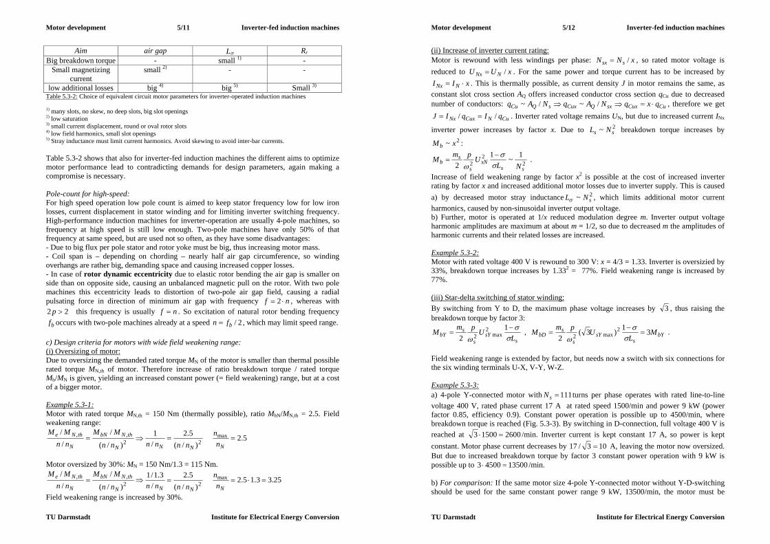
Motor development 5/11 Inverter-fed induction machines
TU Darmstadt Institute for Electrical Energy Conversion
Aim air gap L Rr Big breakdown torque - small 1) -
Small magnetizing current
small 2) - -
low additional losses big 4) big 5) Small 3) Table 5.3-2: Choice of equivalent circuit motor parameters for inverter-operated induction machines 1) many slots, no skew, no deep slots, big slot openings 2) low saturation 3) small current displacement, round or oval rotor slots 4) low field harmonics, small slot openings 5) Stray inductance must limit current harmonics. Avoid skewing to avoid inter-bar currents. Table 5.3-2 shows that also for inverter-fed induction machines the different aims to optimize motor performance lead to contradicting demands for design parameters, again making a compromise is necessary. Pole-count for high-speed: For high speed operation low pole count is aimed to keep stator frequency low for low iron losses, current displacement in stator winding and for limiting inverter switching frequency. High-performance induction machines for inverter-operation are usually 4-pole machines, so frequency at high speed is still low enough. Two-pole machines have only 50% of that frequency at same speed, but are used not so often, as they have some disadvantages: - Due to big flux per pole stator and rotor yoke must be big, thus increasing motor mass. - Coil span is – depending on chording – nearly half air gap circumference, so winding overhangs are rather big, demanding space and causing increased copper losses. - In case of rotor dynamic eccentricity due to elastic rotor bending the air gap is smaller on side than on opposite side, causing an unbalanced magnetic pull on the rotor. With two pole machines this eccentricity leads to distortion of two-pole air gap field, causing a radial pulsating force in direction of minimum air gap with frequency nf 2 , whereas with
22 p this frequency is usually nf . So excitation of natural rotor bending frequency
bf occurs with two-pole machines already at a speed 2/bfn , which may limit speed range. c) Design criteria for motors with wide field weakening range: (i) Oversizing of motor: Due to oversizing the demanded rated torque MN of the motor is smaller than thermal possible rated torque MN,th of motor. Therefore increase of ratio breakdown torque / rated torque Mb/MN is given, yielding an increased constant power (= field weakening) range, but at a cost of a bigger motor. Example 5.3-1: Motor with rated torque MN,th = 150 Nm (thermally possible), ratio MbN/MN,th = 2.5. Field weakening range:
5.2)/(
5.2/1
)/(
/// max
22,,
NNNN
thNbN
N
thNe
nn
nnnnnn
MMnnMM
Motor oversized by 30%: MN = 150 Nm/1.3 = 115 Nm.
25.33.15.2)/(
5.2/
3.1/1)/(
/// max
22,,
NNNN
thNbN
N
thNe
nn
nnnnnn
MMnnMM
Field weakening range is increased by 30%.
Motor development 5/12 Inverter-fed induction machines
TU Darmstadt Institute for Electrical Energy Conversion
(ii) Increase of inverter current rating: Motor is rewound with less windings per phase: xNN ssx / , so rated motor voltage is reduced to xUU NNx / . For the same power and torque current has to be increased by
xII NNx . This is thermally possible, as current density J in motor remains the same, as constant slot cross section AQ offers increased conductor cross section qCu due to decreased number of conductors: CuCuxsxQCuxsQCu qxqNAqNAq /~/~ , therefore we get
CuNCuxNx qIqIJ // . Inverter rated voltage remains UN, but due to increased current INx
inverter power increases by factor x. Due to 2~ ss NL breakdown torque increases by 2~ xMb :
22
21~1
2 sssN
s
sb NL
UpmM
.
Increase of field weakening range by factor x2 is possible at the cost of increased inverter rating by factor x and increased additional motor losses due to inverter supply. This is caused a) by decreased motor stray inductance 2~ sNL , which limits additional motor current harmonics, caused by non-sinusoidal inverter output voltage. b) Further, motor is operated at 1/x reduced modulation degree m. Inverter output voltage harmonic amplitudes are maximum at about m = 1/2, so due to decreased m the amplitudes of harmonic currents and their related losses are increased. Example 5.3-2: Motor with rated voltage 400 V is rewound to 300 V: x = 4/3 = 1.33. Inverter is oversizied by 33%, breakdown torque increases by 1.332 = 77%. Field weakening range is increased by 77%. (iii) Star-delta switching of stator winding: By switching from Y to D, the maximum phase voltage increases by 3 , thus raising the breakdown torque by factor 3:
ssY
s
sbY L
UpmM
1
22
max2 , bYs
sYs
sbD M
LUpmM 31)3(
22
max2
.
Field weakening range is extended by factor, but needs now a switch with six connections for the six winding terminals U-X, V-Y, W-Z. Example 5.3-3: a) 4-pole Y-connected motor with 111sN turns per phase operates with rated line-to-line voltage 400 V, rated phase current 17 A at rated speed 1500/min and power 9 kW (power factor 0.85, efficiency 0.9). Constant power operation is possible up to 4500/min, where breakdown torque is reached (Fig. 5.3-3). By switching in D-connection, full voltage 400 V is reached at 260015003 /min. Inverter current is kept constant 17 A, so power is kept constant. Motor phase current decreases by 103/17 A, leaving the motor now oversized. But due to increased breakdown torque by factor 3 constant power operation with 9 kW is possible up to 1350045003 /min. b) For comparison: If the same motor size 4-pole Y-connected motor without Y-D-switching should be used for the same constant power range 9 kW, 13500/min, the motor must be

Motor development 5/13 Inverter-fed induction machines
TU Darmstadt Institute for Electrical Energy Conversion
equipped with 663/111 sN turns per phase, yielding an increase in inverter current
rating of 30317 A, which usually is more expensive than the Y-D-switch for 17 A.
Fig. 5.3-3: Field weakening with constant power 9 kW: (a) Y-connected motor with decreased number of turns per phase, (b) Y-D-switching of winding, c) Increase of inverter current rating for b) (iv) Series-parallel switching of stator winding:
Fig. 5.3-4: Possible motor current, voltage and power rating for the same motor size and torque, but a) series and b) parallel connection of each phase: With parallel winding number of turns is only 50%, so for the same rated voltage the rated frequency and current is 200%, thus increasing motor power by factor 2 If e.g. for a four pole motor the number of turns per winding Ns is split into two halves (one for first and one for second pole pair, each Ns/2), one can switch those two halves either in series or in parallel. In parallel the total number of turns per phase is with Ns/2 only 1/2 of the
Motor development 5/14 Inverter-fed induction machines
TU Darmstadt Institute for Electrical Energy Conversion
series value Ns, thus breakdown torque increases by factor 2))2//(( ss NN 4, allowing 4-times larger field weakening range in parallel than in series (Fig. 5.3-5). In parallel switching mode for the SAME inverter current rating the current per parallel winding branch is only 50% of rated current, so motor is oversized in parallel winding field weakening operation by factor 2 (Fig. 5.3-4). As each phase is split into two halves, a series-parallel switch for 12 terminals is needed: U1-X1, U2-X2, V1-Y1, V2-Y2, W1-Z1, W2-Z2.
Fig. 5.3-5: Series-parallel switching for increasing constant power range by factor 4 a) Breakdown power Pb = 2nMb ~ 1/n, current, voltage and power for series connected winding b) Operation with parallel connected winding allows increase of field weakening by factor 4 from 1:2.5 to 1:10
a) b) Fig. 5.3-6: Catalogue examples for maximum motor power versus speed at voltage source inverter supply for motor size 160 mm: S1: thermal steady state operation, S3-60%: intermittent operation: 6 minutes overload, 4 minutes stand still, S6-60%: intermittent operation: 6 minutes overload, 4 minutes no load a) High performance 4-pole induction motor with star-delta switch to enlarge constant power range, rated speed at Y: 500/min, rated frequency 16.7 Hz b) Standard induction 4-pole motor, D connected winding, rated speed 1460 /min, rated frequency 50 Hz

Motor development 5/15 Inverter-fed induction machines
TU Darmstadt Institute for Electrical Energy Conversion
5.4 Influence of inverter harmonics on motor performance a) Inverter voltage time harmonics: Inverter line-to-line output voltage is a series of rectangular shaped voltage impulses of varying duration due to PWM (Fig. 5.4-2). Fourier analysis yields voltage harmonics, depending of modulation degree m. Usually the switching frequency of inverter transistors is fixed (fT = const.), independent of fundamental frequency fk=1 = fs (asynchronous switching). For bigger power ratings e.g. with GTO-inverters the ratio fT/fs is fixed and an integer odd number, but may be changed for different values, e.g. 9, 15, ... (synchronous switching). In case of asynchronous switching usually switching frequency is high enough fT/fs >> 1 (e.g. 3 ... 10 kHz), that one can always take fT/fs integer odd number. In Fig. 5.4-2 example for synchronous switching fT/fs = 12000 Hz/800 Hz = 15 is given for different modulation degrees is given, yielding different fundamental line-to-line voltage amplitudes kLLU ,
ˆ as a complete spectrum, depending on modulation degree, or – in other words – depending on fundamental voltage amplitude.
max,1,1......0)10...5...(...0 kssk UUm Often in inverters upper limit is modulation degree m = 1, leaving over-modulation as additional voltage margin for current control. At over-modulation PWM converts into six-step voltage mode (compare Fig. 5.4-2a with Fig. 5.4-2c). Phase voltage for star connected stator winding is derived from line-to-line voltage according to Fig. 5.4-1a
)()()( 2121 tututu LLSS (5.4-1) )()()( 3232 tututu LLSS (5.4-2) 0)()()( 321 tututu SSS . (5.4-3)
Thus phase voltage of phase 1 ("U") is
3)()(2)( 3221
1tututu LLLL
S
, (5.4-4) yielding in case of over-modulation a step-like time-function (Fig. 5.4-1b) with amplitude 2Ud/3 .
Fig. 5.4-1: Star connection of stator winding: a) Phase voltage uS and line-to-line voltage uL, b) Time-function of line-to-line voltage uL and phase voltage uS in case of six step operation
Motor development 5/16 Inverter-fed induction machines
TU Darmstadt Institute for Electrical Energy Conversion
In case of delta connected winding line-to-line voltage is also phase voltage. Fig. 5.4-1b shows clearly, that in case of star connection the voltage time-function fits better to ideal sine time-function than in case of delta connection. Conclusions: Inverter fed machines are usually operated in star connection, as phase voltage time function fits better to ideal sine wave. Frequencies of voltage harmonics are ssk fkf , and inverter generates three phase voltage system for each time harmonic k.
))3/4(cos(ˆ)(
))3/2(cos(ˆ)(
)cos(ˆ)(
tkUtu
tkUtu
tkUtu
sSkWk
sSkVk
sSkUk
(5.4-5)
Example 5.4-1: k = 1: phase sequence U, V, W: clockwise rotating air gap field
)3/4cos(ˆ)()3/2cos(ˆ)()cos(ˆ)( 111111 tUtutUtutUtu sSWsSVsSU k = 5: phase sequence U, V, W: clockwise rotating air gap field
)3/205cos(ˆ)()3/105cos(ˆ)()5cos(ˆ)( 555555 tUtutUtutUtu sSWsSVsSU This can also be written as
)3/25cos(ˆ)()3/45cos(ˆ)()5cos(ˆ)( 555555 tUtutUtutUtu sSWsSVsSU , which means that phase V and W for 5th harmonic have changed phase shift, yielding: k = 5: phase sequence U, W, V: counter-clockwise rotating air gap field. Time-harmonic three-phase voltage system, applied to stator winding as stator voltage Usk with frequency fsk causes time-harmonic three-phase current system Isk, which excites air gap flux density Bsk, which may be expressed as Fourier sum of space-harmonics
,...7,5,1, )cos(),(
tkxBtxB s
p
sskssk (5.4-6)
with wave speed of fundamental space harmonic of kth current system
psksyn kfv 21,, . (5.4-7) So inverse rotation of air gap field of e.g. 5th time-harmonic current system is described mathematically correct, if we define the ordinal number k as negative number k = -5. Result of Fourier analysis of Fig. 5.4-2 is: Line-to-line voltage spectrum contains in case of synchronous switching as ordinal numbers k all odd numbers, which are not dividable by 3 (due to the 3-phase system):
gk 61 , ,...4,3,2,1,0 g (5.4-8) Negative sign means that sequence of phase voltages change their position (U, W, V instead of U, V, W), yielding current system in motor, which excites inverse rotating air gap magnetic fields.

Motor development 5/17 Inverter-fed induction machines
TU Darmstadt Institute for Electrical Energy Conversion
Conclusions: Do not mix up the formulas gk 61 for ordinal number of three-phase time-harmonic voltage and current harmonics, and g61 for ordinal number of space-harmonics of air-gap field, excited by three-phase winding system. First is defined by inverter, independent of motor design, second is defined by winding arrangement in motor, independent of inverter design. In both cases negative sign of ordinal number means, that the air gap field is inverse rotating.
Fig. 5.4-2: Line-to-line pulse width modulated voltage in per unit of DC link voltage Ud, and its Fourier spectrum for synchronous switching mode fT/fs = 12000 Hz/800 Hz = 15 for different modulation degree m a) PWM with m = 0.5, b) PWM with m = 1, c) over-modulation m = 5, which yields six step voltage supply Fig. 5.4-2 shows that for low modulation degree dominating amplitudes of voltage time-harmonics occur at frequencies TsT fff 22 (Fig. 5.4-2a), and therefore often Tp ff 2 is defined as pulse frequency, as number of positive and negative voltage impulses in line-to-
Motor development 5/18 Inverter-fed induction machines
TU Darmstadt Institute for Electrical Energy Conversion
line voltage is given by fp/fs (e.g. Fig. 5.4-2: 30/15/ spsT ffff : 15 positive and 15 negative voltage impulses). At modulation degree near unity dominating amplitudes of voltage time-harmonics occur at switching frequency TsT fff 2 (Fig. 5.4-2b), whereas with over-modulation (six step mode) voltage harmonics decrease with inverse of ordinal number (Fig. 5.4-2c). Conclusions: At medium modulation degree twice switching frequency voltage harmonics ("pulse-frequent" voltage ripple) is dominating as harmonic voltage content (Fig. 5.4-3).
Fig. 5.4-3: Harmonic amplitudes of line-to-line PWM voltage Fourier analysis: (1) Fundamental k = 1, (2) , (3) harmonics at k fT/fs , (4), (5) harmonics at k 2fT/fs , depending on modulation degree m Example 5.4-2: Fourier voltage harmonics in six-step mode: a) Line-to-line voltage:
,...19,17,13,11,7,5,132)3/sin(4ˆ
)cos(ˆ)(
,
1,
kkU
kkUU
tkUtu
ddkLL
kskLLLL
(5.4-9)
b) For deriving phase voltage, one has to evaluate eq. (5.4-4) for each harmonic. If we take time co-ordinate so that like in (5.4-9) fundamental voltage amplitude occurs at t = 0, we get :
,...19,17,13,11,7,5,161)1(2)2/sin(2ˆ
)cos(ˆ)(
,
1,
gkkU
kkUU
tkUtu
gddkS
kskSS
(5.4-10)
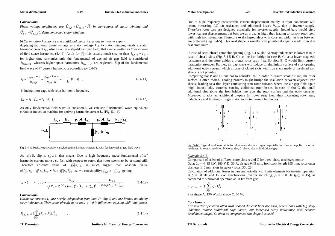
Motor development 5/19 Inverter-fed induction machines
TU Darmstadt Institute for Electrical Energy Conversion
Conclusions: Phase voltage amplitudes are 3/ˆˆ
,, kLLkS UU in star-connected stator winding and
kLLkS UU ,,ˆˆ in delta connected stator winding.
b) Current time harmonics and additional motor losses due to inverter supply: Applying harmonic phase voltage as stator voltage Usk to stator winding yields a stator harmonic current Isk, which excites a step-like air gap field, that can be written as Fourier sum of field space harmonics (5.4-6). As Isk for 1k is usually much smaller than 1,1, sks II , for higher time-harmonics only the fundamental of excited air gap field is considered
1, skB , whereas higher space harmonics 1, skB are neglected. Slip of the fundamental
field wave of kth current harmonic is according to (5.4-7)
)1(11,
, skkn
nknn
nns
syn
syn
ksyn
ksynk
, (5.4-11)
inducing rotor cage with rotor harmonic frequency
skskkrk fksfsf . (5.4-12) As only fundamental field wave is considered, we can use fundamental wave equivalent circuit of induction machine for deriving harmonic current Isk (Fig. 5.4-4).
Fig. 5.4-4: Equivalent circuit for calculating time harmonic current Isk with fundamental air gap field wave As 5k , slip is 1ks , that means: Due to high frequency space fundamental of kth harmonic current moves so fast with respect to rotor, that rotor seems to be at stand-still. Therefore absolute value of hs Lkj is much bigger than absolute value
of rsrrskr LkjRLkjsR / , so we can simplify: krks II ,, , getting
)()(1 ,
222,
,
rss
ks
rssrs
ksksk LLk
U
LLkRR
UIs
(5.4-13)
Conclusions: Harmonic currents Is,k are nearly independent from load (= slip s) and are limited mainly by stray inductance. They occur already at no-load s = 0 in full extent, causing additional losses
2,
1, )(3 ks
krsinvad IRRP
. (5.4-14)
Motor development 5/20 Inverter-fed induction machines
TU Darmstadt Institute for Electrical Energy Conversion
Due to high frequency considerable current displacement mainly in rotor conductors will occur, increasing AC bar resistance and additional losses Pad,inv due to inverter supply. Therefore rotor bars are designed especially for inverter supply. Round bars would yield lowest current displacement, but bars are as broad as high, thus leading to narrow rotor teeth with high iron saturation. Therefore oval shaped slots with constant width teeth in between are preferred (Fig. 5.4-5). This oval shape is usually only possible if cage is made from die-cast aluminium. In case of semi-closed rotor slot opening (Fig. 5.4-5, slot A) stray inductance is lower than in case of closed slots (Fig. 5.4-5 B, C), as the iron bridge in case B, C has a lower magnetic resistance and therefore guides a bigger rotor stray flux. So slots B, C would limit current harmonics stronger. Further, air gap wave will induce in aluminium surface of slot opening additional eddy current, which in case of closed slots with iron stack made of insulated iron sheets is not possible. Comparing slot B and C, one has to consider that in order to ensure small air gap, the rotor surface is often tooled. Tooling process might bridge the insulation between adjacent iron sheets, leading to a thin layer conducting iron rotor surface, where the air gap field again might induce eddy currents, causing additional rotor losses. In case of slot C, the small additional slot above the iron bridge interrupts the rotor surface and the eddy currents. Moreover it adds an additional by-pass for rotor stray flux, thus increasing rotor stray inductance and limiting stronger stator and rotor current harmonics.
Fig. 5.4-5: Typical oval rotor slots for aluminium die cast cages, especially for inverter supplied induction machines: A: semi-closed slot, B: closed slot, C: closed slot with additional gap Example 5.4-3: Comparison of effect of different rotor slots A and C for three-phase unskewed motor Data: 2p = 4, 15 kW, 380 V D, 30 A, air gap 0.45 mm, iron stack length 195 mm, rotor outer diameter 145 mm, slots in stator / rotor: 36 / 28. Calculation of additional losses in bars numerically with finite elements for inverter operation at fs = 50 Hz and 15 kW, synchronous inverter switching, fT = 750 Hz (fT/fs = 15), as compared to sinusoidal operation at 50 Hz from grid:
2,
1,, kr
krrinvrad IRQP
Slot shape A: 190 W, slot shape C: 60 W. Conclusions: For inverter operation often oval shaped die cast bars are used, where bars with big stray induction reduce additional cage losses, but increased stray inductance also reduces breakdown torque. So often as compromise slot shape B is used.

Motor development 5/21 Inverter-fed induction machines
TU Darmstadt Institute for Electrical Energy Conversion
Increased losses e.g. with slot shape A yield increased temperature in motor, typically in stator winding up to 5 K, which sometimes might lead to slight motor de-rating to stay within thermal limit of applied thermal motor class. A further method to decrease current harmonics is to raise inverter switching frequency fT. From Chapter 4.2 we know that due to current displacement AC bar resistance increases by ratio kEbarRk dhk ,/ with penetration depth (conductivity , permeability of rotor bar conductor)
srkkE fkfd /1/1, . (5.4-15) Losses in bar conductors are therefore for kth harmonic
2
2,2
,2,~,, ))(( rss
ksrRkrkrrRkrkrrrinvrad LLk
URkQIRkQIRQP
or
22,,, /~ kUkP ksinvrad . (5.4-16)
Increasing switching frequency e.g. at medium modulation degree means increasing of ordinal number sT ffk /2 , where dominant voltage harmonic Us,k occurs. With increase of k voltage harmonic is reduced, but current harmonic is reduced much stronger by Us,k/k, so losses in rotor bars decrease according to (5.4-16). On the other hand switching losses in power transistors of inverter rise linear with switching frequency, so optimum for minimum system losses (= overall drive efficiency) has to be found. Example 5.4-4: Standard 2-pole motor, 3 kW, 380 V Y is fed by voltage source inverter with asynchronous switching with rating 8.3 kVA, 12 A rated current, 400 V. Motor is operated at fs = 50 Hz with slip s = 4.5% at 10 Nm (rated power 3 kW), loading the inverter with 54% of rated inverter current. Motor and inverter efficiency was measured by directly measuring input and output power both of motor and inverter for different inverter switching frequency.
grid operation inverter operation fs / Hz 50 50 50 50 fT / Hz - 2 400 4 800 9 600
fp = 2fT / kHz 4.8 9.6 19.2 Efficiency motor 81.9 % 81.3 % 81.4 % 81.4 %
Efficiency inverter - 96.9 % 96.8 % 95.9 %Overall efficiency 81.9 % 78.8 % 78.8 % 78.1 %
Table 5.4-1: Measured motor, inverter and overall efficiency of 3 kW motor at different inverter switching frequency As inverter is only partially loaded, its efficiency is lower than at rated point, which is 97%. This is due to constant load independent losses such as current supply for controller electronics and fan blower.
Conclusions: At fP = 9.6 kHz overall motor efficiency is higher (motor heating is lower), and overall efficiency is the same as at 4.8 kHz. At 19.2 kHz current ripple reduction in motor is already negligible, but inverter losses increase considerably. In Fig. 5.4-6 and Fig. 5.4-7 the corresponding measured time functions of line-to-line voltage and of motor phase current along with the Fourier spectra are shown for switching frequency 2.4 kHz and 4.8 kHz. Inverter operates at DC link voltage Ud = 525 V. Note that oscilloscope
Motor development 5/22 Inverter-fed induction machines
TU Darmstadt Institute for Electrical Energy Conversion
resolution was not sufficient to display PWM pattern of line-to-line voltage for a whole period appropriate. Only in the zoomed time function the voltage pulse is visible correctly.
ULL,k Is,k Is,k / Is,k=1 fs 50 Hz 372 V 6.2 A 100 %
2fT - fs 4750 Hz 89.5 V 0.18 A 2.9 % 2fT + fs 4850 Hz 91.3 V 0.18 A 2.9 % 4fT - fs 9550 Hz 38.6 V 0.035 A 0.6 % 4fT + fs 9650 Hz 24.8 V 0.027 A 0.4 %
Table 5.4-1: Measured Fourier spectrum of line-to-line voltage and phase motor current at 2.4 kHz inverter switching frequency (see Example 5.4-4) Note that overall r.m.s. of voltage e.g. at 2.4 kHz switching frequency
1
2,,
kkLLrmsLL UU (5.4-17)
is with 403, rmsLLU V much bigger than r.m.s.-value of fundamental (372 V) due to voltage harmonics. Current harmonics are small, so total current r.m.s. 25.6, rmssI A is nearly the same as r.m.s. of fundamental 6.2 A. Current is close to sine wave, so current measured peak 9.65 A is nearly the same as 2.92.622 1, ksI A. From Table 5.4-1 we derive with (5.4-13) total motor stray inductance
61.918.047502
3/5.893/,
sksk
kLLrs I
ULLL mH
and current amplitude at e.g. 9550 Hz with
6.3800961.0955023/6.38
)(3/,
rssk
kLLsk LL
UI mA ,
which fits well to the measured value 35 mA, proving the value of presented theory. Measured current ripple is the sum of all current Fourier harmonics and is of triangular shape, as it is explained in Chapter 1. In case that voltage impulse width is the same as voltage gap in between, peak-to-peak of current ripple is maximum. Considering in Y-connection the stray inductance of two phases for line-to-line voltage value Ud and frequency of voltage impulses as double switching frequency, we get as maximum peak-to-peak current ripple 2.8 A, which fits well to the measurement Fig. 5.4-6.
AfL
Ui
fTttiLUdtdiLu
p
d
ppd
8.2480000961.04
5254
:2/12/,/2/
The 5th and 7th inverter voltage harmonic are rather small at this modulation degree, e.g. 5th voltage line-to-line r.m.s. measured value is 2.9 V at 250505 Hz, yielding with (5.4-13) harmonic current 11.0)00961.025023/(9.25, sI A; measured value is 0.09A. Note that this motor has been already investigated at sinusoidal voltage supply (Example 4.4.1-5), showing due to rotor slot space harmonics additional stator current harmonics at about 950 Hz and 1150 Hz with r.m.s. current harmonics 0.08 A and 0.05 A, which are also visible in Fig. 5.4-6 and Fig. 5.4-7.
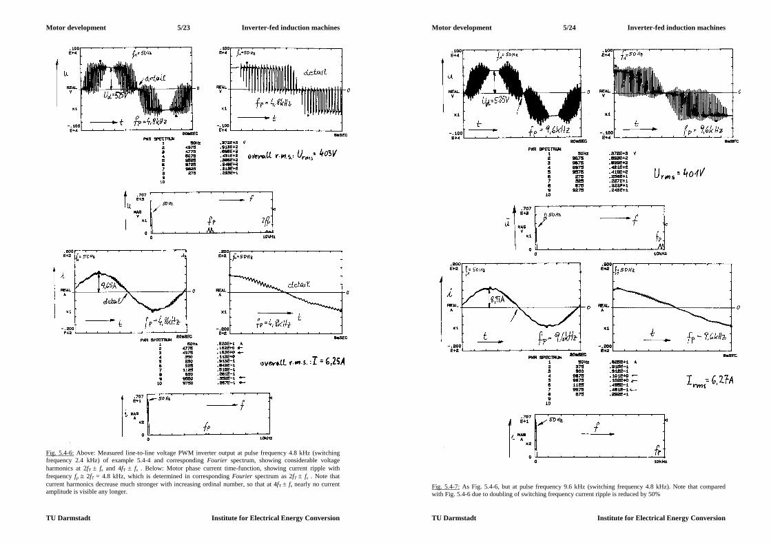
Motor development 5/23 Inverter-fed induction machines
TU Darmstadt Institute for Electrical Energy Conversion
Fig. 5.4-6: Above: Measured line-to-line voltage PWM inverter output at pulse frequency 4.8 kHz (switching frequency 2.4 kHz) of example 5.4-4 and corresponding Fourier spectrum, showing considerable voltage harmonics at 2fT fs and 4fT fs . Below: Motor phase current time-function, showing current ripple with frequency fp 2fT = 4.8 kHz, which is determined in corresponding Fourier spectrum as 2fT fs . Note that current harmonics decrease much stronger with increasing ordinal number, so that at 4fT fs nearly no current amplitude is visible any longer.
Motor development 5/24 Inverter-fed induction machines
TU Darmstadt Institute for Electrical Energy Conversion
Fig. 5.4-7: As Fig. 5.4-6, but at pulse frequency 9.6 kHz (switching frequency 4.8 kHz). Note that compared with Fig. 5.4-6 due to doubling of switching frequency current ripple is reduced by 50%
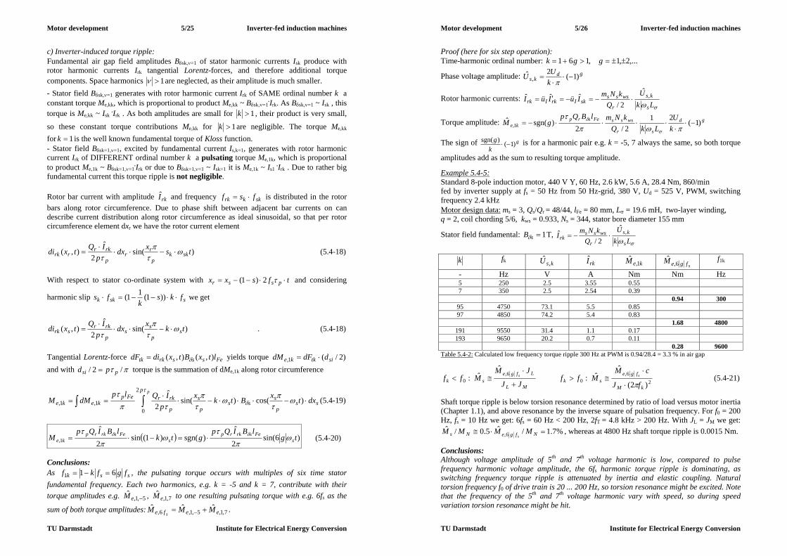
Motor development 5/25 Inverter-fed induction machines
TU Darmstadt Institute for Electrical Energy Conversion
c) Inverter-induced torque ripple: Fundamental air gap field amplitudes Bsk,=1 of stator harmonic currents Isk produce with rotor harmonic currents Irk tangential Lorentz-forces, and therefore additional torque components. Space harmonics 1 are neglected, as their amplitude is much smaller. - Stator field Bsk,=1 generates with rotor harmonic current Irk of SAME ordinal number k a constant torque Me,kk, which is proportional to product Me,kk ~ Bsk,=1
.Irk. As Bsk,=1 ~ Isk , this torque is Me,kk ~ Isk
.Irk . As both amplitudes are small for 1k , their product is very small,
so these constant torque contributions Me,kk for 1k are negligible. The torque Me,kk for 1k is the well known fundamental torque of Kloss function. - Stator field Bsk=1,=1, excited by fundamental current Is,k=1, generates with rotor harmonic current Irk of DIFFERENT ordinal number k a pulsating torque Me,1k, which is proportional to product Me,1k ~ Bsk=1,=1
.Irk or due to Bsk=1,=1 ~ Isk=1 it is Me,1k ~ Is1 .Irk . Due to rather big
fundamental current this torque ripple is not negligible. Rotor bar current with amplitude rkI and frequency skkrk fsf is distributed in the rotor bars along rotor circumference. Due to phase shift between adjacent bar currents on can describe current distribution along rotor circumference as ideal sinusoidal, so that per rotor circumference element dxr we have the rotor current element
)sin(2
ˆ),( tsxdx
pIQtxdi skk
p
rr
p
rkrrrk
(5.4-18)
With respect to stator co-ordinate system with tfsxx pssr 2)1( and considering
harmonic slip sskk fksk
fs ))1(11( we get
)sin(2
ˆ),( tkxdx
pIQtxdi s
p
ss
p
rkrsrk
. (5.4-18)
Tangential Lorentz-force Fesssrktk ltxBtxdidF ),(),( yields torque )2/(1, sitkke ddFdM and with /2/ psi pd torque is the summation of dMe,1k along rotor circumference
s
p
sp
sss
p
s
p
rkrFepkeke dxtxBtkx
pIQlp
dMMp
2
01,1, )cos()sin(
2
ˆ(5.4-19)
)6sin(2
ˆ)sgn()1(sin
2
ˆ1, tg
lBIQpgtk
lBIQpM s
Fesrkrps
Fesrkrpke
(5.4-20)
Conclusions: As ssk fgfkf 611 , the pulsating torque occurs with multiples of six time stator fundamental frequency. Each two harmonics, e.g. k = -5 and k = 7, contribute with their torque amplitudes e.g. 5,1,
ˆeM , 7,1,
ˆeM to one resulting pulsating torque with e.g. 6fs as the
sum of both torque amplitudes: 7,1,5,1,6,ˆˆˆ
eefe MMMs
.
Motor development 5/26 Inverter-fed induction machines
TU Darmstadt Institute for Electrical Energy Conversion
Proof (here for six step operation): Time-harmonic ordinal number: ,...2,1,161 ggk
Phase voltage amplitude: gdks k
UU )1(2ˆ,
Rotor harmonic currents: Lk
UQ
kNmIüIüIs
ks
r
wsssskIrkIrk
,ˆ
2/ˆˆˆ
Torque amplitude: gd
sr
wsssFesrpke k
ULkQ
kNmlBQpgM )1(
212/2
)sgn(ˆ1,
The sign of gk
g )1()sgn( is for a harmonic pair e.g. k = -5, 7 always the same, so both torque
amplitudes add as the sum to resulting torque amplitude. Example 5.4-5: Standard 8-pole induction motor, 440 V Y, 60 Hz, 2.6 kW, 5.6 A, 28.4 Nm, 860/min fed by inverter supply at fs = 50 Hz from 50 Hz-grid, 380 V, Ud = 525 V, PWM, switching frequency 2.4 kHz Motor design data: ms = 3, Qs/Qr = 48/44, lFe = 80 mm, L = 19.6 mH, two-layer winding, q = 2, coil chording 5/6, kws = 0.933, Ns = 344, stator bore diameter 155 mm
Stator field fundamental: 1sB T, Lk
UQ
kNmIs
ks
r
wsssrk
,ˆ
2/ˆ
k fk ksU ,ˆ rkI keM 1,
ˆ sfgeM 6,ˆ f1k
- Hz V A Nm Nm Hz 5 250 2.5 3.55 0.55 7 350 2.5 2.54 0.39 0.94 300
95 4750 73.1 5.5 0.85 97 4850 74.2 5.4 0.83
1.68 4800 191 9550 31.4 1.1 0.17 193 9650 20.2 0.7 0.11
0.28 9600 Table 5.4-2: Calculated low frequency torque ripple 300 Hz at PWM is 0.94/28.4 = 3.3 % in air gap
26,
06,
0 )2(
ˆˆ:
ˆˆ:
kM
fgesk
ML
Lfgesk fJ
cMMff
JJ
JMMff ss
(5.4-21)
Shaft torque ripple is below torsion resonance determined by ratio of load versus motor inertia (Chapter 1.1), and above resonance by the inverse square of pulsation frequency. For f0 = 200 Hz, fs = 10 Hz we get: 6fs = 60 Hz < 200 Hz, 2fT = 4.8 kHz > 200 Hz. With JL = JM we get:
%7.1/ˆ5.0/ˆ6, NfgeNs MMMM
s, whereas at 4800 Hz shaft torque ripple is 0.0015 Nm.
Conclusions: Although voltage amplitude of 5th and 7th voltage harmonic is low, compared to pulse frequency harmonic voltage amplitude, the 6fs harmonic torque ripple is dominating, as switching frequency torque ripple is attenuated by inertia and elastic coupling. Natural torsion frequency f0 of drive train is 20 ... 200 Hz, so torsion resonance might be excited. Note that the frequency of the 5th and 7th voltage harmonic vary with speed, so during speed variation torsion resonance might be hit.
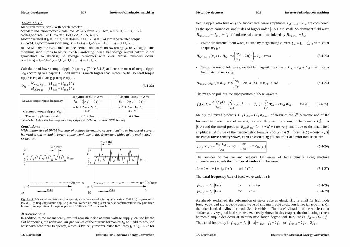
Motor development 5/27 Inverter-fed induction machines
TU Darmstadt Institute for Electrical Energy Conversion
Example 5.4-6: Measured torque ripple with accelerometer: Standard induction motor: 2 pole, 750 W, 2850/min, 2.51 Nm, 400 V D, 50 Hz, 1.6 A Voltage-source IGBT Inverter: 1500 VA, 2.2 A, 400 V Motor operated at fs =1.2 Hz, n = 20/min, s = 0.72, M = 1.24 Nm = 50% rated torque a) PWM, asynchronous switching: ,...2,1,0,...13,11,7,5,161 ggk b) PWM only for two thirds of one period, one third no switching (zero voltage): This switching mode leads to lower inverter switching losses, but voltage output pattern is not symmetrical to abscissa, so voltage harmonics with even ordinal numbers occur:
,...2,1,0,...13,11,10,8,7,5,4,2,131 ggk Calculation of lowest torque ripple frequency (Table 5.4-3) and measurement of torque ripple
Mw according to Chapter 1. Load inertia is much bigger than motor inertia, so shaft torque ripple is equal to air gap torque ripple.
2/)(2/)(ˆ
ˆminmax
minmaxMMMM
MM
waverage
coggingM
(5.4-22)
a) symmetrical PWM b) asymmetrical PWM Lowest torque ripple frequency
Hzffgf ssk
2.72.16661
Hz
ffgf ssk
6.32.13331
Measured torque ripple Mw 14.4% 35.0% Torque ripple amplitude 0.18 Nm 0.43 Nm
Table 5.4-3: Calculated low frequency torque ripple at PWM for different PWM feeding Conclusions: With asymmetrical PWM increase of voltage harmonics occurs, leading to increased current harmonics and to double torque ripple amplitude at low frequency, which might excite torsion resonance.
Fig. 5.4-8: Measured low frequency torque ripple at low speed with a) symmetrical PWM, b) asymmetrical PWM. High frequency torque ripple e.g. due to inverter switching is not seen, as accelerometer is low pass filter. In case b) superposition of torque ripple with 3.6 Hz and 7.2 Hz is visible. d) Acoustic noise In addition to the magnetically excited acoustic noise at sinus voltage supply, caused by the slot harmonics, the additional air gap waves of the current harmonics Isk will add to acoustic noise with new tonal frequency, which is typically inverter pulse frequency fp = 2fT. Like for
Motor development 5/28 Inverter-fed induction machines
TU Darmstadt Institute for Electrical Energy Conversion
torque ripple, also here only the fundamental wave amplitudes sksk IB ~1, are considered,
as the space harmonics amplitudes of higher order 1 are small. So dominant field wave
ssksk IIB 11,1 ~ of fundamental current is modulated by sksk IB ~1, :
- Stator fundamental field wave, excited by magnetizing current rsm III Is with stator frequency fs :
cos2cos),(1,1
ss
p
ssssk BtfxBtxB . (5.4-23)
- Stator harmonic field wave, excited by magnetizing current rkskmk III Is with stator harmonic frequency fsk :
cos2cos),(1,
sks
p
sskssk BtfkxBtxB . (5.4-24)
The magnetic pull due the superposition of these waves is
kkBBBfBtxBtxfk
ksskskknk
sks
sn
1
21,
2
10
22~)(~
2),(),(
. (5.4-25)
Mainly the mixed products 1 skskkssk BBBB of fields of the kth harmonic and of the
fundamental current are of interest, because they are big enough. The squares 2skB for
1k and the mixed products kssk BB for 1 kk are very small due to the small field amplitudes. With use of the trigonometric formula )cos()cos(coscos2 the radial force density waves, exert an oscillating pull on stator and rotor iron stack, are
)22
2cos(2
),( ,0
1, tfpxrBBtxf kTon
p
ssksskn
. (5.4-26)
The number of positive and negative half-waves of force density along machine circumference equals the number of nodes 2r in between:
ppr 41122 ("+") and 0 ("-") (5.4-27) The tonal frequency fTon,k of force wave variation is
kff skTon 1, for pr 42 (5.4-28)
kff skTon 1, for 02 r . (5.4-29) As already explained, the deformation of stator yoke as elastic ring is small for high node force wave, and the acoustic sound wave of this multi-pole excitation is not far reaching. On the other hand, the vibration mode 2r = 0 yields to "in-phase" vibration of the whole motor surface as a very good loud-speaker. As already shown in this chapter, the dominating current harmonic amplitudes occur at medium modulation degree with frequencies sTsk fff 2 . Thus tonal frequency is TsskskTon fffkff 21, or sTkTon fff 22, .

Motor development 5/29 Inverter-fed induction machines
TU Darmstadt Institute for Electrical Energy Conversion
Conclusions: Inverter caused magnetic noise is usually excited with twice switching frequency ("pulse frequency"). Force amplitude is depending on motor main flux and stator current harmonics. Therefore inverter-induced magnetic noise occurs already at no-load, as both main flux and current harmonics Isk are at their full value already at no-load.
skskmskwsss
skn IIIp
IkNmBF
~~2
21ˆ 0
01, (5.4-30)
By increasing inverter switching frequency acoustic noise may be reduced, because - harmonic current is reduced, - at high frequencies beyond 6 kHz human ear is decreasingly sensitive, - vibration amplitude of mechanical structure decreases with increased frequency. Magnetically excited acoustic noise depends on speed range: In the constant torque range
Nnn 0 flux is constant and big, so noise is big. In the constant power range flux is weakened by )/( nnNN and therefore magnetic noise decreases. In case of standard induction motors with shaft mounted fan the mechanical noise of the fan increases with speed, containing mainly the "fan blade frequency" nzf z with z as number of fan blades. Example 5.4-7: Measurement of sound pressure level LpA in 1 m distance of motor in acoustic chamber, where walls contain sound-absorbing glass fibre cones, so no reflections of sound waves occur. Sound pressure level Lp (with human audibility level 5
0 102 p Pa) is measured as average value of 8 microphones
appL pA )/lg(20 0 , (5.4-31) and is weighted with factor a to simulate frequency-dependent sensitivity of human ear. 4 pole cage standard induction motor, size 71 mm (shaft height), with shaft-mounted fan and data: 250 W, 400 V D, 50 Hz, fed from IGBT-inverter with 400 VA, capable of different switching frequencies 1 kHz, 2 kHz, 4 kHz, 8 kHz, leading to audible noise with pulse frequency 2 kHz, 4 kHz, 8 kHz, 16 kHz. Fig. 5.4-9 shows, that increase of switching frequency above 2 kHz decreases pAL considerably up to 25 dB(A) at low speed. With switching frequency 8 kHz the current ripple (at 16 kHz) is so small, that current is nearly sinusoidal. So no difference in noise to ideal sinusoidal voltage operation (generated from synchronous test-field generator with variable frequency) occurs. Above 1500/min flux is weakened and sound pressure level is reduced at 1 and 2 kHz switching frequency. At high speed the noise of the fan is dominating. Noise of fan increases theoretically with
)/lg(50 12 nnLp , (5.4-32) thus between 1500/min and 6000/min by 30 dB, which is well in coincidence with measurement at 8 kHz switching frequency. For big motors it is not easy to raise inverter switching frequency to reduce audible noise, as due to increased switching losses the power transistors must be oversized, which is expensive at big power. As audible tone with pulse frequency (e.g. 2 kHz) may be experienced really
Motor development 5/30 Inverter-fed induction machines
TU Darmstadt Institute for Electrical Energy Conversion
nasty, some manufacturers of inverters offer a control strategy with wobbling of switching frequency. Switching frequency varies between e.g. 1 kHz and 2 kHz periodically with e.g. a sine function. So the tonal frequency varies also. One experiences a frequency mix instead of a tonal fixed frequency. This sound is to many people more convenient, but sometimes resembles to that kind of noise, if motor bearings were damaged.
Fig. 5.4-9: Measured A-weighted sound pressure level at 1 m distance of 250 W, PWM inverter-fed induction motor, varying with speed and switching frequency fT, corresponding with pulse frequency fp = 2fT . e) Influence of air gap field space harmonics at inverter-operation: Asynchronous and synchronous harmonic torque due to slotting occur at big slip (typically between s = 0.8 ... 1.2), so inverter-fed motors – being operated usually between full-load slip and zero slip – should not be influenced by these parasitic torque components. Nevertheless, at low speed, full-load slip increases up to unity, so that space harmonic torque will be in the range of motor operation. Yet, motor current is in the range of rated current and not –as with line-started induction motors – in the range o 500% rated current. So these parasitic torque components remain small and negligible (see Example 5.4-8). Example 5.4-8: Calculation of space harmonic torque with numerical finite element calculation method for unskewed 4-pole cage induction motor, 15 kW, 380 V, D, 50 Hz, 30 A, 1430/min, 100 Nm, Qs/Qr = 36 / 28. a) Harmonic torque at fs =50 Hz line-operation (This was calculated in Example 4.4.2-1): (i) Asynchronous harmonic torque due to = -11 stator field harmonic with harmonic synchronous speed min/1361500)09.11()1( synnsn . (ii) Synchronous harmonic torque at slip 0.86 due to harmonics 13 occurs at 215/min with amplitude 150 Nm. b) Harmonic torque at fs = 1.5 Hz inverter-operation (Fig. 5.4-10): (ii) Synchronous harmonic torque at slip 0.86 due to harmonics 13 occurs at 6.3/min with amplitude 5 Nm.
a) 50 Hz line operation b) 1.5 Hz inverter operation Synchronous speed 1500/min 45/min
speed at rated torque 98 Nm 1460/min 5/min slip at rated torque 98 Nm 2.6 % 88.9 % rotor frequency at 98 Nm 1.3 Hz 1.3 Hz
current at slip 0.86 (synchronous harmonic torque)
550 % rated current 100% rated current
speed at synchronous torque 215/min 6.3 /min Synchronous torque amplitude 150 Nm 5 Nm
Table 5.4-4: Harmonic synchronous torque at inverter-operation is very small, as motor operates only up to due rated motor current, avoiding the big starting currents of line-operated machines
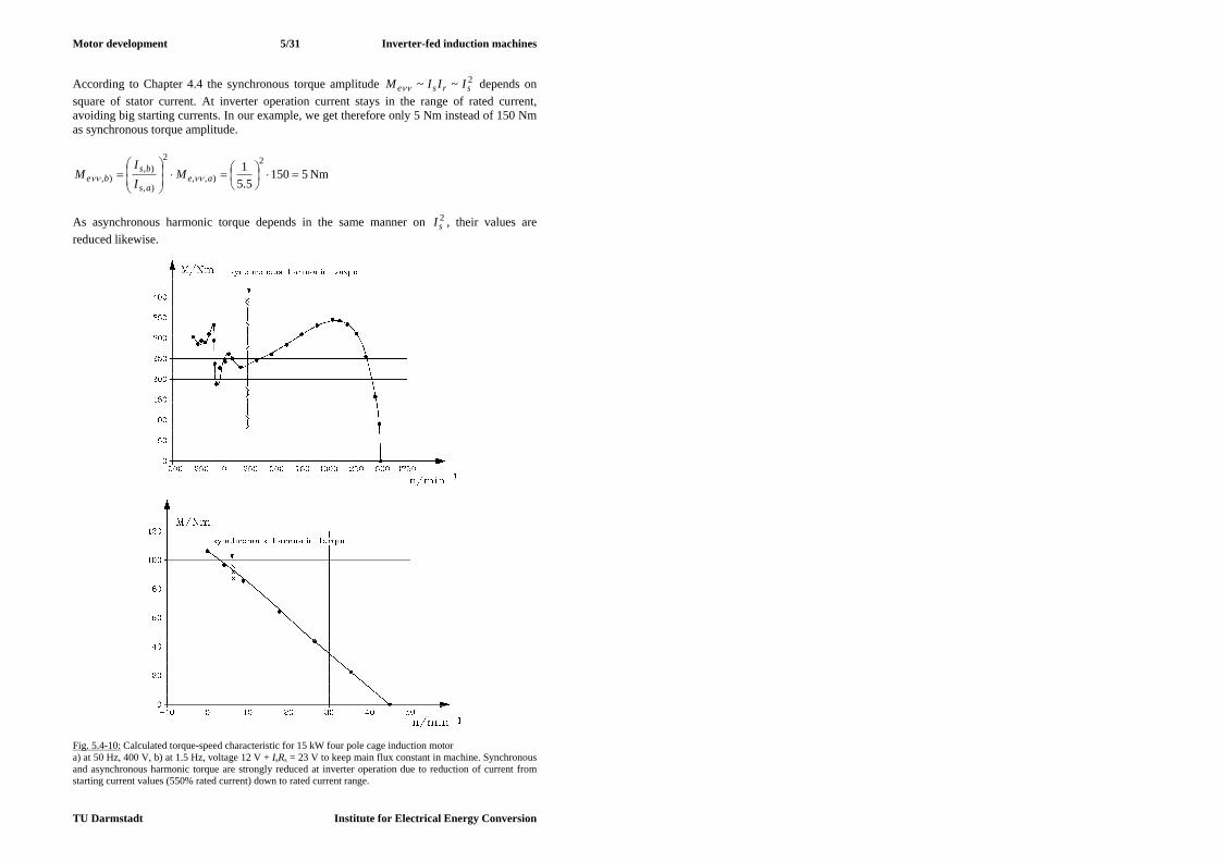
Motor development 5/31 Inverter-fed induction machines
TU Darmstadt Institute for Electrical Energy Conversion
According to Chapter 4.4 the synchronous torque amplitude 2~~ srse IIIM depends on square of stator current. At inverter operation current stays in the range of rated current, avoiding big starting currents. In our example, we get therefore only 5 Nm instead of 150 Nm as synchronous torque amplitude.
51505.5
1 2
),,
2
),
),),
ae
as
bsbe M
II
M Nm
As asynchronous harmonic torque depends in the same manner on 2
sI , their values are reduced likewise.
Fig. 5.4-10: Calculated torque-speed characteristic for 15 kW four pole cage induction motor a) at 50 Hz, 400 V, b) at 1.5 Hz, voltage 12 V + IsRs = 23 V to keep main flux constant in machine. Synchronous and asynchronous harmonic torque are strongly reduced at inverter operation due to reduction of current from starting current values (550% rated current) down to rated current range.

Motor development 6/1 du/dt- effects in inverter-fed machines
TU Darmstadt Institute for Electrical Energy Conversion
6. du/dt-effects in inverter-fed machines 6.1 Voltage wave reflection at motor terminals a) Wave propagation on loss-free motor cable with reflection coefficients 1 and –1: Fast switching IGBT inverters allow voltage rise time tr between zero and dc link voltage of down to typically 100 ns. Depending on dc link voltage, a rather big voltage change rate du/dt is given.
rd tUdtdu // (6.1-1) Example 6.1-1: Typical values du/dt in IGBT inverters for voltage rise time tr = 100 ns:
Line supply dc link voltage rd tUdtdu // Single phase 230 V 50 Hz 310 V 3.1 kV/s Three phase 400 V 50 Hz 560 V 5.6 kV/s Three phase 500 V 50 Hz 700 V 7.0 kV/s Table 6.1-1: Typical change rate of inverter output voltage for fast switching IGBT inverters Conclusions: Typical voltage change rates du/dt of low voltage IGBT inverters range between 3 to 8kV/µs. High voltage IGBT inverters with voltage levels of several kV show the same rates du/dt, as high-volt IGBT switching is slower, but dc link voltage is bigger, compared with low voltage inverters. Thus du/dt is much bigger than the demand for motor insulation according to VDE0530/1, Amendment 2: ULL <1000V, du/dt < 500V/µs). Between motor and inverter the motor cable is guiding the voltage impulses from the inverter to the motor as electromagnetic wave with velocity of light. Cable consists of copper or aluminium wire with insulation (PVC, PE) in between. Voltage between two phases of cable and current in the cable conductors generates electromagnetic field E and B, which are determined by permittivity of dielectric insulation and magnetic permeability .
00 , rr . (6.1-2)
Velocity of E- and B-wave propagation in material with permittivity and permeability is given by
rrrr
cv
0
00
11 , (6.1-3)
where c0 is velocity of light in vacuum. As dielectric insulation defines capacitance per cable length C´cable and magnetic permeability defines inductance per cable length L´cable, wave propagation velocity of loss-free cable may also be written as
cablecablerr CLcv
10
(6.1-4)
Example 6.1-2: a) c0 : velocity of light in vacuum:
120 10854.8 As/(Vm), 7
0 104 Vs/(Am) : 8
000 10998.21
c m/s
Motor development 6/2 du/dt- effects in inverter-fed machines
TU Darmstadt Institute for Electrical Energy Conversion
b) v : velocity of light in motor cable:
4r , 1r : 80 10499.14
cv m/s
Conclusions: Velocity of electromagnetic wave in motor cable is typically 150 km/ms, which is about half of velocity of light in vacuum. Neglecting rise time (tr = 0), we consider for each voltage impulse of inverter PWM output a voltage step either from 0 to Ud or from Ud to 0, which is travelling from inverter to motor with velocity v. The inverter may considered as a voltage source with zero internal impedance at high frequency, as the dc link capacitor stabilizes the dc link voltage and has an impedance
)/(1 CZinv , which is small at high frequencies. The AC motors (synchronous or asynchronous machines) may be regarded as very high impedance, as their armature winding
impedance sssmot LLRZ 22 )( is very big at high frequencies. Motor wave impedance is determined by high frequency voltage distribution within motor winding (see Chapter 6.2), so the formula presented here is only a rough estimate. Example 6.1-3: Three-phase four-pole standard induction motor, 400 V, Y, 50 Hz, 1.1 kW, frame size 90 mm (= shaft height), total stray inductance at 50 Hz: 50 mH, Stray inductance at wave reflection frequency fd = 300 kHz (see Example 6.1-4) is much smaller due to the strong current displacement in motor conductors and is estimated here with 5 mH, yielding calculated value 4.9105103002 33 sdmot LZ k. Measured motor wave impedance is smaller: Zmot = 5000 . Difference is explained by the reason, that at high frequencies fd = 300 kHz also stray capacities within motor winding have to be considered to calculate Zmot . The same holds true for inverter wave impedance Zinv , where at high frequencies also stray inductance of inverter cabling has to be considered. So in fact different formulas for invmot ZZ , are needed for exact determination of motor and inverter wave impedance. Conclusions: Calculation of wave impedance of motor winding and inverter is rather complicated due to high frequency effects, taking stray capacitance in motor and stray inductance in inverter into account. Nevertheless we conclude that usually the motor wave impedance is significantly bigger and the inverter wave impedance is significantly smaller than the cable wave impedance. This is proven by measurement. Cable as wave guide between inverter and motor has the cable wave impedance, which can be calculated easily for homogeneous cable as
cable
cable
cablecable
cablecablecable C
LCGLRZ
422
22
)()(
, (6.1-5)
where we will neglect cable losses (resistance per cable length R´cable per phase and conductance per cable length G´cable of insulator between phases), yielding typical values between 50 and 100 Ohm. Example 6.1-4: PVC-insulated cable H05VVF4G1.5: 4 x 1.5 mm2, (3 phases U, V, W and one PE (potential equalizer) conductor): conductor diameter d = 1.4 mm, 5.14/2 dq mm2, distance

Motor development 6/3 du/dt- effects in inverter-fed machines
TU Darmstadt Institute for Electrical Energy Conversion
between conductor centres (= conductor diameter + insulation thickness): a = 4.15 mm, average relative permittivity: 4r . HF current flows on conductor surface, so no inner conductor inductance to be considered.
Cable phase outer inductance per unit length: 36.0)/2ln(2
0 daLcable H/m
Cable phase capacitance per unit length: 125)/2ln(/2 0 daC rcable pF/m
Cable wave impedance: 7.53
cable
cablecable C
LZ (measured: 83 )
Wave velocity : 6101491
cablecableCLv m/s
The propagation path of the voltage wave is not homogenous at both ends, where impedance changes abruptly, causing wave reflection and wave refraction. Reflected part of wave is thrown back on cable, whereas refracted part of wave penetrates into connected medium with impedance Z. Reflection coefficient r between cable and another medium with wave impedance Z is given by ratio of amplitude of reflected wave and incoming wave:
cable
cable
incom
reflected
ZZZZr
uu
. (6.1-6)
Fig. 6.1-1: Wave reflection and refraction at border between cable (1) and motor (2) For further simplification we consider motor impedance to be infinite and inverter impedance to be zero. Then we get wave propagation between voltage source (inverter) and open cable end (motor) according to Fig. 6.1-2, yielding reflection coefficient at motor and inverter terminals +1 and –1:
1:
motmotcablemot
cablemotmot rZ
ZZZZr , (6.1-7)
1:0
invinvcableinv
cableinvinv rZ
ZZZZr . (6.1-8)
Reflection due to voltage wave propagation between inverter and motor with cable length l is as follows, if. e.g. switching from 0 to Ud = U occurs. (1): Line-to-line voltage between two cable phases rises from 0 to Ud = U and travels as voltage wave from position (z = 0) to end of cable (z = l) with propagation time tp = l/v . (6.1-9) There voltage reflection with r = 1 happens, causing due to superposition of incoming and reflecting wave for resulting voltage ures a doubling of voltage amplitude 2U:
Motor development 6/4 du/dt- effects in inverter-fed machines
TU Darmstadt Institute for Electrical Energy Conversion
UUUUrUuruuulzu rres 2)( (6.1-10)
Fig. 6.1-2: Oscillation of voltage at open cable end due to wave reflection at both ends of cable (loss-free cable) Above: cable with open end, below: voltage wave propagation along cable, bottom: voltage time function at both cable ends (2): Reflected voltage wave travels back during time tp towards inverter, while at the open end (motor side) voltage value 2U remains constant. Due to inverter internal impedance Zinv = 0 at inverter output terminals we get wave reflection r = -1 . Thus reflected voltage inverses from ur = U to ur,r = –U; so voltage at inverter output remains constant:
UUUUururuuuuzu invmotrrrres ,)0( . (6.1-11) (3): Reflected wave –U runs again forward to open end of cable (motor side) during time tp and is reflected there again with rmot = r = 1. As reflected wave with amplitude –U wave is travelling back to inverter terminals. At open cable end (motor side) due to this reflection we get voltage –2U, which is superimposed on voltage 2U from (6.1-10). So resulting voltage at motor side is cancelled to zero: -2U + 2U = 0.
0222)(22)( UUUUrUUuruUuulzu rres (6.1-12)

Motor development 6/5 du/dt- effects in inverter-fed machines
TU Darmstadt Institute for Electrical Energy Conversion
(4): Voltage wave, travelling back with –U during tp, is reflected at inverter side with r = -1 from –U to U , leaving resulting voltage at inverter side unchanged at U. Now the whole process starts again with section (1), leading to an oscillation of voltage at motor side with period T and frequency fd:
cablecableccableccablecablecablecp CLlClLCLlvltT 4´´4´´444 (6.1-13)
cablecabled CL
Tf4
1/1 (6.1-14)
Conclusions: Compared with a lumped parameter model per phase of loss-free cable, consisting of one concentrated capacitance Ccable and one concentrated inductance Lcable per phase with natural frequency )2/(1 cablecabled CLf , the real behaviour of the cable is that of a wave
conductor. So natural frequency is )4/(1 cablecabled CLf . Motor terminal line-to-line
voltage oscillates between 0...2 dU , so voltage overshoot is 21/ˆ, motdmotLL rUU . This
over-voltage leads to increased insulation stress in the motor armature. Example 6.1-5: Cable length lc = 100 m, wave velocity on cable 610150 v m/s, dc link voltage 560 V, motor reflection coefficient 1motr .
Line to line over-voltage at motor terminals: 11205602)1(ˆ, dmotmotLL UrU V
Wave propagation time: 67.0)10150/(100/ 6 vlt cp s
Oscillation frequency: 3754
1)4/(1 cablecable
pd CLtf kHz
b) Wave propagation on loss-free motor cable with reflection coefficients r 1 :
Fig. 6.1-3: Oscillation of voltage at motor side of open cable end due to wave reflection at both ends of cable (loss-free cable) with reflection coefficient 0.75 on motor side and –1 at inverter side. Voltage rise time neglected.
Motor development 6/6 du/dt- effects in inverter-fed machines
TU Darmstadt Institute for Electrical Energy Conversion
As shown in (6.1-7), (6.1-8) the real motor reflection coefficient is about 9.0...7.0motr , the inverter reflection coefficient is 9.0invr . This influence on oscillation of motor voltage is depicted in Fig. 6.1-3, where it is assumed, that 75.0motr and 1invr . Reflected voltage
at motor terminals is dr Uu 75.0 , voltage overshoot is 75.11/ˆ, motdmotLL rUU . At
inverter reflected voltage is dr Uu 75.0 , being again reflected at motor terminals after time 3tp as ddr UUu 56.075.075.0 . After reflection at inverter terminals
ddr UUu 56.0)56.0( , the voltage is reflected at motor terminals after time 5tp as
ddr UUu 42.075.075.075.0 and so on. As a result the amplitude of oscillation of terminal voltage with frequency fd is decreasing to reach finally the value of Ud. Conclusions: With motor reflection coefficient < 1 the voltage overshoot motdmotLL rUU 1/ˆ
, is a value between 1 and 2, leading to increased insulation stress in the motor armature. Wave impedance of motor cables Zcable is more or less independent from rated cable current, which determines conductor cross section to get a rated current density of about 2 ... 3 A/mm2, depending on cable arrangement and cable cooling. As shown, the wave propagation of E and B occurs in the insulation layer between cable conductors. Thickness of this insulation, which also defines distance between phase conductors, is determined by voltage rating of cable and determines parameters cablecable CL , . Therefore for low voltage motors the wave impedance of motor cables for different current ratings is more or less the same. Motor impedance is determined by smot LZ . With the same voltage rating, but increased motor size ( = increased motor power and motor current rating) the number of turns per phase Ns decrease due to stator voltage equation 2/swssss kNU , as flux per pole
increases with motor size according to pBld sFesis / . Due to 2~ ss NL motor impedance decreases with increased motor size. Conclusions:
Motor reflection coefficient cablemot
cablemotmot ZZ
ZZr
is decreasing with increasing motor size, as
the ratio 1/ cablemot ZZ for same voltage rating, but increasing motor size is also decreasing. Therefore smaller motors are exposed to higher voltage overshoot than bigger motors and are therefore more endangered. Example 6.1-6: a) Small 1.1 kW-motor: - Three-phase four-pole standard induction motor, 400 V, Y, 50 Hz, 1.1 kW, 2.1 A, frame
size 90 mm (= shaft height), measured motor wave impedance 5000 Ohm. - Motor cable 4 x 1.5 mm2, Type H05VVF4G1.5, (3 phases U, V, W and one PE (potential
equalizer) conductor): cable current density: 4.15.1/1.2 J A/mm2, wave impedance 83 Ohm.
Motor reflection coefficient: 967.0835000835000
motr
b) Bigger 18.5 kW-motor: - Three-phase four-pole standard induction motor, 400 V, Y, 50 Hz, 18.5 kW, frame size
180 mm (= shaft height), measured motor wave impedance 570 Ohm. - Motor cable wave impedance 75 Ohm.
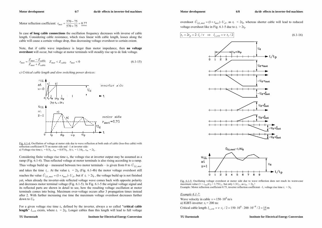
Motor development 6/7 du/dt- effects in inverter-fed machines
TU Darmstadt Institute for Electrical Energy Conversion
Motor reflection coefficient: 77.07557075570
motr
In case of long cable connections the oscillation frequency decreases with inverse of cable length. Considering cable resistance, which rises linear with cable length, losses along the cable will cause a certain voltage drop, thus decreasing voltage overshoot to certain extent. Note, that if cable wave impedance is larger than motor impedance, then no voltage overshoot will occur, but voltage at motor terminals will steadily rise up to dc link voltage.
0
motcablemotcablemot
cablemotmot rZZ
ZZZZr (6.1-15)
c) Critical cable length and slow switching power devices:
Fig. 6.1-4: Oscillation of voltage at motor side due to wave reflection at both ends of cable (loss-free cable) with reflection coefficient 0.75 on motor side and –1 at inverter side: a) Voltage rise time tr = 0.5tp , trm = 0.875tp , b) tr = 1.14tp , trm = 2tp . Considering finite voltage rise time tr, the voltage rise at inverter output may be assumed as a ramp (Fig. 6.1-4). Thus reflected voltage at motor terminals is also rising according to a ramp. Thus voltage build up – measured between two motor terminals – is given from 0 to motLLU ,
ˆ and takes the time rt . At the value tr = 2tp (Fig. 6.1-4b) the motor voltage overshoot still reaches the value dmotmotLL UrU )1(ˆ
, , but if tr > 2tp , the voltage build up is not finished yet, when already the inverter-side reflected voltage wave comes back with opposite polarity and decreases motor terminal voltage (Fig. 6.1-5). In Fig. 6.1-5 the original voltage signal and its reflected parts are shown in detail to see, how the resulting voltage oscillation at motor terminals comes into being. Maximum over-voltage occurs after 3 propagation times instead after 2. With further increasing rise time the maximum voltage overshoot decreases further down to Ud. For a given voltage rise time tr, defined by the inverter, always a so called "critical cable length" lc,crit exists, where tr = 2tp. Longer cables than this length will lead to full voltage
Motor development 6/8 du/dt- effects in inverter-fed machines
TU Darmstadt Institute for Electrical Energy Conversion
overshoot dmotmotLL UrU )1(ˆ, , as tr < 2tp, whereas shorter cable will lead to reduced
voltage overshoot like in Fig. 6.1-5 due to tr > 2tp.
2//22 , rcritccpr tvlvltt (6.1-16)
Fig. 6.1-5: Oscillating voltage overshoot at motor side due to wave reflection does not reach its worst-case maximum value (1 + rmot)Ud = 1.75Ud , but only 1.3Ud , as trm > 2tp ! Example: Motor reflection coefficient 0.75, inverter reflection coefficient –1, voltage rise time tr = 3tp Example 6.1-7: Wave velocity in cable 610150 v m/s a) IGBT-inverter: tr = 200 ns: Critical cable length 152/10200101502/ 96
, rcritc tvl m

Motor development 6/9 du/dt- effects in inverter-fed machines
TU Darmstadt Institute for Electrical Energy Conversion
b) GTO-inverter: tr = 5 s: Critical cable length 3752/105000101502/ 96
, rcritc tvl m
For slow switching devices like GTO or thyristors with voltage rise time in the range of several s, this critical cable length is much bigger. That is why only with the advent of fast switching IGBT-inverters the problem of increased voltage stress even to low voltage motors came up, whereas with slow switching bipolar power transistors or GTOs etc. even with long cable connections between motor and inverter no voltage over-stress occurred. Disadvantage of these slow switching devices is of course, that motor speed and torque control is not possible with that dynamic performance. Further increased voltage and harmonic current ripple causes additional motor losses and considerable torque ripple (see Chapter 5).
Fig. 6.1-6: Measured oscillating line-to-line voltage overshoot, 2 pole induction motor, frame size 80 mm, 400 V, Y, fed from IGBT-inverter with motor cable 100 m at fundamental frequency fs = 30 Hz, switching frequency fT = 8 kHz, 600 V dc link voltage Example 6.1-8: 2 pole induction motor, frame size 80 mm, 400 V, Y, fed from IGBT-inverter with motor cable 100 m at fundamental frequency fs = 30 Hz, 600 V dc link voltage (Fig. 6.1-6), PWM, duration of voltage impulse 14 s. Measured oscillating line-to-line voltage overshoot
1150)1(ˆ, dmotmotLL UrU V yields motor reflection coefficient 92.0motr . Measured
oscillation frequency 375)4/(1 pd tf kHz leads to tp = 666 ns and wave velocity in cable of 150 000 km/s. Voltage rise time tr = 500 ns is obviously shorter than 2tp = 1330 ns, so full voltage reflection occurs. 6.2 HF voltage distribution in armature winding Motor winding can be regarded as an equivalent circuit per turn, consisting of inductance per turn L, line-to-earth capacitance CE between conductor and stator iron, defined by the main insulation in slot between winding and iron, and series capacitance Cs between conductors of adjacent turns in slot, spaced by the inter-turn insulation, which in low voltage machines is only the enamel of the copper wire. Due to small conductor surface, but big slot surface,
Motor development 6/10 du/dt- effects in inverter-fed machines
TU Darmstadt Institute for Electrical Energy Conversion
usually CE >> Cs. All turns per phase in series may be therefore regarded as an equivalent circuit as shown in Fig. 6.2-1 a).
a) b) Fig. 6.2-1: a) HF (high frequency) equivalent circuit for armature winding per phase, b) Kirchhoff´s laws applied to one element of equivalent circuit With Ns turns per winding (length of winding per turn is x) the total line-to-earth capacitance CE and total series capacitance per phase Cs is
EsE CNC , sss NCC / , (6.2-1)
and with winding length sNxl we get
EEsE ClxCxNC )/( , lCxNxCC ssss /)/( (6.2-2) or for each turn
xCC EE , xCC ss / . (6.2-3)
Taking infinitesimal winding section dx instead x allows solving the problem as differential equation: dxCdC EE , dxCdC ss / . Considering e.g. star connected winding, a line-to-line voltage step from 0 to Ud (= rise time is assumed to be zero) between two phases can be regarded in that equivalent circuit as a step of potential of left circuit leg by Ud , whereas right leg is at zero voltage. In between are 2Ns turns ( = phases). Due to dtdiLu LL / the current iL shortly before and after applying this voltage step must be zero, as a step in current would lead to infinite voltage uL. Thus for calculating voltage distribution in winding shortly after applying voltage step, only the capacities need to be considered. We apply Kirchhoff´s laws to the equivalent circuit Fig. 6.2-1b for the capacitive currents
dttxdu
dxCxi
dttxdudxCxi ss
sE
EE),()(,),()(
(6.2-4)
and consider infinitesimal calculus dxdxdixidxxi )()( :
)(0)()()( xidxdxdixidxxixi E
sEss (6.2-5)
dxdudx
dxudxudx
dxduxuxudxxu sE
sE
EsE 2
20)(0)()()( (6.2-6)
Combining (6.2-4) and (6.2-5) by eliminating sE ii , we get after time integration:
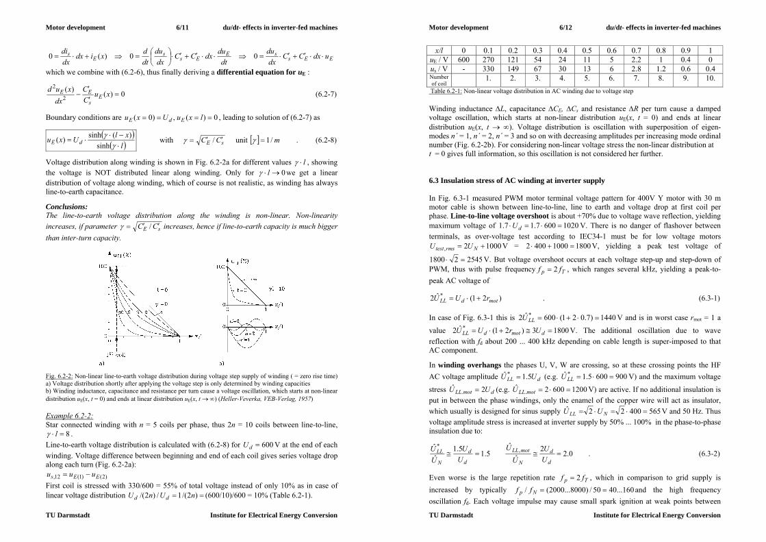
Motor development 6/11 du/dt- effects in inverter-fed machines
TU Darmstadt Institute for Electrical Energy Conversion
EEssE
Ess
Es udxCC
dxdu
dtdudxCC
dxdu
dtdxidx
dxdi
00)(0
which we combine with (6.2-6), thus finally deriving a differential equation for uE :
0)()(2
2
xuCC
dxxud
Es
EE (6.2-7)
Boundary conditions are 0)(,)0( lxuUxu EdE , leading to solution of (6.2-7) as
l
xlUxu dE
sinh
)(sinh)( with sE CC / unit m/1 . (6.2-8)
Voltage distribution along winding is shown in Fig. 6.2-2a for different values l , showing the voltage is NOT distributed linear along winding. Only for 0 l we get a linear distribution of voltage along winding, which of course is not realistic, as winding has always line-to-earth capacitance. Conclusions: The line-to-earth voltage distribution along the winding is non-linear. Non-linearity increases, if parameter sE CC / increases, hence if line-to-earth capacity is much bigger than inter-turn capacity.
Fig. 6.2-2: Non-linear line-to-earth voltage distribution during voltage step supply of winding ( = zero rise time) a) Voltage distribution shortly after applying the voltage step is only determined by winding capacities b) Winding inductance, capacitance and resistance per turn cause a voltage oscillation, which starts at non-linear distribution uE(x, t = 0) and ends at linear distribution uE(x, t ) (Heller-Veverka, VEB-Verlag, 1957) Example 6.2-2: Star connected winding with n = 5 coils per phase, thus 2n = 10 coils between line-to-line,
8 l . Line-to-earth voltage distribution is calculated with (6.2-8) for 600dU V at the end of each winding. Voltage difference between beginning and end of each coil gives series voltage drop along each turn (Fig. 6.2-2a):
)2()1(12, EEs uuu First coil is stressed with 330/600 = 55% of total voltage instead of only 10% as in case of linear voltage distribution )2/(1/)2/( nUnU dd (600/10)/600 = 10% (Table 6.2-1).
Motor development 6/12 du/dt- effects in inverter-fed machines
TU Darmstadt Institute for Electrical Energy Conversion
x/l 0 0.1 0.2 0.3 0.4 0.5 0.6 0.7 0.8 0.9 1 uE / V 600 270 121 54 24 11 5 2.2 1 0.4 0 us / V - 330 149 67 30 13 6 2.8 1.2 0.6 0.4 Number of coil
1. 2. 3. 4. 5. 6. 7. 8. 9. 10. Table 6.2-1: Non-linear voltage distribution in AC winding due to voltage step Winding inductance L, capacitance CE, Cs and resistance R per turn cause a damped voltage oscillation, which starts at non-linear distribution uE(x, t = 0) and ends at linear distribution uE(x, t ). Voltage distribution is oscillation with superposition of eigen-modes n´ = 1, n´ = 2, n´ = 3 and so on with decreasing amplitudes per increasing mode ordinal number (Fig. 6.2-2b). For considering non-linear voltage stress the non-linear distribution at t = 0 gives full information, so this oscillation is not considered her further. 6.3 Insulation stress of AC winding at inverter supply In Fig. 6.3-1 measured PWM motor terminal voltage pattern for 400V Y motor with 30 m motor cable is shown between line-to-line, line to earth and voltage drop at first coil per phase. Line-to-line voltage overshoot is about +70% due to voltage wave reflection, yielding maximum voltage of 10206007.17.1 dU V. There is no danger of flashover between terminals, as over-voltage test according to IEC34-1 must be for low voltage motors
10002, Nrmstest UU V = 180010004002 V, yielding a peak test voltage of
254521800 V. But voltage overshoot occurs at each voltage step-up and step-down of PWM, thus with pulse frequency Tp ff 2 , which ranges several kHz, yielding a peak-to-peak AC voltage of
)21(ˆ2 *motdLL rUU . (6.3-1)
In case of Fig. 6.3-1 this is 1440)7.021(600ˆ2 * LLU V and is in worst case rmot = 1 a
value 18003)21(ˆ2 * dmotdLL UrUU V. The additional oscillation due to wave reflection with fd about 200 ... 400 kHz depending on cable length is super-imposed to that AC component. In winding overhangs the phases U, V, W are crossing, so at these crossing points the HF AC voltage amplitude dLL UU 5.1ˆ * (e.g. 9006005.1ˆ * LLU V) and the maximum voltage
stress dmotLL UU 2ˆ. (e.g. 12006002ˆ
. motLLU V) are active. If no additional insulation is put in between the phase windings, only the enamel of the copper wire will act as insulator, which usually is designed for sinus supply 56540022ˆ NLL UU V and 50 Hz. Thus voltage amplitude stress is increased at inverter supply by 50% ... 100% in the phase-to-phase insulation due to:
0.22ˆ
ˆ5.15.1
ˆˆ ,
*
d
d
N
motLL
d
d
N
LLUU
UU
UU
UU . (6.3-2)
Even worse is the large repetition rate Tp ff 2 , which in comparison to grid supply is increased by typically 160...4050/)8000...2000(/ Np ff and the high frequency oscillation fd. Each voltage impulse may cause small spark ignition at weak points between

Motor development 6/13 du/dt- effects in inverter-fed machines
TU Darmstadt Institute for Electrical Energy Conversion
the phases. These small sparks are called "partial discharges (PD)", as they are too faint to be visible, but repeated very often they will cause erosion of enamel, leading finally to a big flash or phase-to-phase short circuit.
Fig. 6.3-1: Measured motor voltages at PWM IGBT-inverter operation of a 400 V Y-motor at dc link voltage 600 V and 30 m cable length between motor and inverter. a) Line-to-line voltage, b) line to earth voltage, c) voltage drop at first coil per phase (Hentschel, E. et al. etz 114) Therefore only additional phase-to-phase insulation layers (inter-phase lining), which are strong enough to withstand the above noted voltage stress, can avoid partial discharges. Thus inverter-operated motors have to get an improved winding insulation, which is tested during manufacturing by the "partial discharge test" (Fig. 6.3-2). In the example of Fig. 6.3-2 a small synchronous reluctance motor was manufactured with – by accident - displaced inter-phase lining between phases U and V. With increasing line-to-line test voltage at 740 V (corresponding with amplitude 10457402 V) the partial discharges began to occur at 20°C, thus the partial inception (PD) voltage is 740 V for this motor. This is too low for safe operation at increased temperature, as PD voltage decreases with increasing winding
Motor development 6/14 du/dt- effects in inverter-fed machines
TU Darmstadt Institute for Electrical Energy Conversion
temperature by about 4 V/K. Thus a Thermal Class F motor with about 150°C winding temperature needs at 20°C a PD inception voltage (r.m.s.) of about 1200pdU V to be safe at 150°C.
motLLpdpdpd UVUCVUVUC ,ˆ21180)20150(41700:1501700ˆ,1200:20
Fig. 6.3-2: Partial discharge test of stator winding of a 2-pole 400V Y, 50 Hz, synchronous reluctance motor at 20°C. A sinus 50 Hz line-to-line voltage with variable amplitude between the non-connected phases U, V, W is applied. In case of partial discharges the spark discharge currents flow as HF spikes from one phase to the other. Via a HF capacitor this current flow may be detected and is made visible as additional HF voltage, superimposed on testing voltage (Siemens AG). Line-to-earth voltage stress is lower, as can be seen from Fig. 6.3-1b. Potential of each winding changes with the same AC amplitude dmotdLE UrUU 2/ˆ * , (e.g. at 400V-motors
900 V) like line-to-line voltage, but maximum voltage is also only dmotdmotLE UrUU 2/ˆ,
(e.g. 900 V), which is lower than line-to-line value 1200 V. Further AC frequency is only switching frequency fT and not pulse frequency 2fT. Voltage stress of first coil is critical, if the rise time is really short (< 1 s), as then the calculation for tr = 0 in Chapter 6.2 is valid. Enforced inter-turn insulation is necessary to cope with this increased voltage stress especially for first coil per phase. In Fig. 6.3-1c the voltage peak of first coil cU at each pulse switching instant is visible, which then is damped down to linear voltage distribution )2/( nUd . Measured voltage overload in that Fig. 6.3-1c is
about 8))2/(/(ˆ nUU dc , so in case of 2n = 10 first coil bears 80% of dc link voltage. Conclusions: At fast-switching IGBT-inverter supply low voltage AC winding insulation of AC motors is stressed with additional voltage due to voltage reflection at motor terminals and due to non-linear voltage distribution in AC winding. Therefore improved winding insulation is necessary to increase partial discharge inception voltage up to 1200 V r.m.s. at 20°C, which is sufficient for 400 V-inverter operation. 6.4 System design of inverter drives coping with big du/dt a) Increased voltage stress of motor winding: Apart from improving motor insulation often additional filter combination at the inverter output are used. Such du/dt-filters consist of chokes and small capacities to increase voltage

Motor development 6/15 du/dt- effects in inverter-fed machines
TU Darmstadt Institute for Electrical Energy Conversion
rise time. Thus the inverter is still fast switching, but the motor terminal voltage has an increased voltage rise time, which may decrease voltage overshoot and non-linear voltage distribution in motor winding. Moreover, high frequency voltage components on motor cable, which may cause electromagnetic interference (EMI) in adjacent cabling, are reduced. Best results are achieved with sine wave filters, which is an L-C combination with resonance frequency )2/(10 LCf lying between fundamental frequency fs and high frequency components fsk of inverter output voltage. This low-pass filter reduces high frequency voltage harmonics, so that inverter line-to-line voltage is more or less sinusoidal, but these filters are expensive. b) Capacitive motor cable currents: Due to high switching frequency fT and the short voltage rise time tr the motor cable capacitance Ccable causes big current spikes
r
dcablecableC t
UCdtduCi . (6.4-1)
Especially with long cables ccablecable lCC capacity and therefore current spikes are big. Thus inverter current limit may be reached even at motor no-load. By using inverter output chokes, which are used especially at long cable above 30 ... 50 m, these current spikes are reduced, so that no over-sizing of inverter is necessary. c) Motor bearing currents: c1) Bearing currents at sinusoidal voltage supply: In case of magnetic asymmetries in line-fed motors under sinusoidal supply a shaft voltage may be induced with line frequency, multiples of it or slot frequency (Fig. 6.4-1). If this voltage surpasses about 0.7 V (peak), the insulating lubricant film is punctured and electric bearing currents may occur, which can damage the bearing races ("fluting"), thus leading to increased bearing noise and finally to bearing failure. Critical bearing current densities lie above 0.1 ... 0.3 A/mm2. Especially big motors above frame size 500 mm and then especially two-pole motors, where the flux per pole is biggest (hence also the parasitic ring-flux ΔΦ due to magnetic asymmetries), are sensitive to bearing currents, caused by magnetic asymmetries. As the shaft voltage causes a bearing voltage drop at both bearings with opposite sign, the bearing current flows as LF circulating current from bearing via stator housing to the other bearing and the shaft. By insulating one bearing this kind of bearing current is interrupted.
Fig. 6.4-1: Induction of an AC voltage by a magnetic AC ring flux ΔΦ. This voltage occurs as shaft voltage between the two shaft ends. This shaft voltage may cause – especially in big two-pole machines – a harmful circulating bearing current ib.
Motor development 6/16 du/dt- effects in inverter-fed machines
TU Darmstadt Institute for Electrical Energy Conversion
c2) Bearing currents at inverter supply: In addition to the effect of magnetic asymmetries, additional high-frequency bearing currents may occur at inverter supply at already much smaller motors. Under inverter supply the stray capacitance of the lubricant film of the bearing – in addition with the winding line-to-earth capacitance and the capacitance of the air gap between stator and rotor – acts as a capacitive voltage divider. The "common mode voltage" u0 as the average line-to-earth potential difference of the stator winding
)(3
)()()(3
)()()()( EWVUWEVEUE
0 tttttutututu
(6.4-2)
changes polarity due to inverter switching with switching frequency, so very often, and with IGBT voltage rise-time, so very fast (Fig. 6.4-2) ( )()()( EUUE tttu ,
)()()( EVVE tttu , )()()( EWWE tttu ). Note that at sinusoidal symmetrical voltage supply with 120° phase shift between the phase voltages the common voltage is zero, as the star potential φY is then equal to zero, so identical with earth potential φ0 = 0.
Fig. 6.4-2: Generation of common mode voltage of stator winding at inverter supply as average line-to-earth potential of the winding:
a) Star-connected three-phase stator winding with electrical potential at terminals, at star-point and earth-potential.
b) At two-level PWM inverters the common mode voltage has values +Ud/2, +Ud/6, -Ud/6, -Ud/2. Due to the fast change rate of the common mode voltage at each switching instant the parasitic capacities of the electric motor are loaded and unloaded with a capacitive current:

Motor development 6/17 du/dt- effects in inverter-fed machines
TU Darmstadt Institute for Electrical Energy Conversion
The already discussed big line-to-earth capacity of the winding via the main insulation in the slots to the housing CE = Cwh (Fig. 6.2-1) in the range of several hundreds of nF causes a HF line-to-earth capacitive current iE. The much smaller parasitic capacities (several pF) between winding and rotor iron Cwr, between rotor iron and stator housing Crh and in parallel from rotor iron via the bearings (bearing capacity Cb) to the earthed housing cause very small, negligible capacitive currents, but give rise to considerable HF bearing voltage ub via the voltage divider (Fig. 6.4-3) („bearing voltage ratio BVR“):
brhwr
wr
0
b2CCC
CuuBVR
(6.4-3)
a)
b)
c) Fig. 6.4-3: Parasitic capacities in electric machines, loaded via the common mode voltage of inverter: a) Electrical equivalent circuit of a ball bearing at HF-voltage stress. The non-linear impedance Zn is zero, if the lubricant film is punctured either by electrical break-down or by the balls at low speed n < 100/min, and is roughly infinite at intact insulating lubricant film at elevated speed. b) Parasitic capacities between stator winding w, rotor iron r, stator housing h, c) Capacitive voltage divider (equivalent circuit) for arrangement b). The impedances Zb of both bearings are acting electrically in parallel and consist acc. to a) each of the elements Cb, Rb, Zn. At the bearings and intact lubricant film with a typical BVR = 3 % … 10 % a bearing voltage of 30)2/600(1.0)2/(max,0max, db UBVRuBVRu V may occur. Due to this high voltage the insulting lubricant film breaks suddenly down electrically, causing electric
Motor development 6/18 du/dt- effects in inverter-fed machines
TU Darmstadt Institute for Electrical Energy Conversion
discharge bearing currents ib,HF. So due to this puncture of lubricant film harmful bearing current spikes occur with the same harmful results as at line operation bearing currents – again fluting of the baring races will lead to mechanical failure of the bearings. This effect due to discharge bearing current is called electric discharge machining (EDM) of the bearing races. The discharge bearing currents occur at both bearings with same polarity (common-mode HF bearing current), so insulating the bearing might not interrupt them. Special common mode filters at the inverter output – which reduce u0 to harmless small values – are needed to avoid a bearing voltage build up. Another possibility is the use of ceramic bearings, which reduces the electric field strength in the lubricant film even at 30 V bearing voltage, thus avoiding film discharge.
a)
b) Fig. 6.4-4: a) Generation of a HF ring-flux Φc, excited by the stator winding line-to-earth HF current iE (Example: Four-pole cage induction machine: The earth current iE – flowing from the inverter to the machine - enters the winding phases at the terminals, but does not leave at the coil ends back to the inverter, but flows via the slot insulation to the stator housing. Si in machine cross section only one current direction is active, causing via Ampere´s law a ring flux). b) Measurement of circulating bearing current at no-load of an inverter fed standard cage induction motor (Frame size 400 mm, two pole, rated power 500 kW) at fundamental frequency fs = 50 Hz, 3000/min; bearing temperature 70 °C (Siemens AG) In addition to this common-mode HF bearing currents also HF circulating bearing currents may occur at inverter supply (differential mode HF bearing currents). The reason for this is the following: At bigger motors the capacitive winding line-to-earth current iE is big enough
Earth current iE from stator winding to earthed housing: 20 A/Div
Circulating bearing current ib : 5 A/Div Non-drive end bearing
Drive-end bearing Time: 1 s/Div

Motor development 6/19 du/dt- effects in inverter-fed machines
TU Darmstadt Institute for Electrical Energy Conversion
to excite an additional parasitic magnetic flux (Fig. 6.4-4a), which may induce an additional rotor shaft voltage like in the case of magnetic asymmetries, causing a HF circular bearing current flow (Fig. 6.4-4b). This kind of current usually is even more harmful than the discharge bearing currents, as its amplitude is bigger, especially at low speed, where the thickness of lubricant film is small or even punctured by the balls. This circulating HF bearing current may be interrupted effectively by insulating one bearing.
6.5 Combined inverter-motors a) Basic idea of inverter integration: By integrating the inverter into the enlarged terminal box of the motor on gets a combined inverter-motor (Fig. 6.5-1). Thus motor and inverter are a compact unity, avoiding the long cable between motor and inverter. This motor is operated below critical cable length and voltage overshoot at motor terminals is negligible. Further, EMI problems due to HF voltage on motor cable are avoided, too. b) Design considerations and applications: In order to get the inverter into the motor terminal box, usually dc link capacitor has to be reduced in size. Thus dc link voltage is not smoothened very well, causing a considerable voltage and current ripple due to line-side harmonics.
a) b) Fig. 6.5-1: Combined inverter-motors a) left: 3 kW / 1500/min standard induction motor with gear box to increase torque and inverter integrated in terminal box of motor, right: integrated inverter bottom side with cooling fins for the IGBT power transistors (SEWeurodrive, Bruchsal), b) small (< 100 W) PM brushless dc synchronous motor with integrated inverter as fan drive for application in computers (ebm Papst) Motor size is determined by torque, whereas inverter size is determined by power. So low speed, high torque motors are big in size, but power is small to moderate. Thus it is easy to integrate rather small inverter into big motor. For example, low speed PM synchronous drives in submarines, powered by fuel-cells, offer enough space within the hollow rotor bell to house the feeding inverter. With high speed motors usually it is not possible to integrate inverter into motor, as power is big, but motor is small. Medium speed motors such as 1000 ... 1500/min ... 3000/min allow inverter integration up to about 7.5 kW. At bigger power ratings dc link capacitor, power module and cooling plate of inverter are too big to be integrated easily. Thus combined inverter-motors in that speed range of 2- to 6-pole induction motors with frequency up to about 100 Hz are available on the
Motor development 6/20 du/dt- effects in inverter-fed machines
TU Darmstadt Institute for Electrical Energy Conversion
market with rated power between several Watt (as fan blowers in computer and other electronics) and about 7.5 kW. In that power range many drives are used as variable speed pump drives in warm water heating, drives for conveyor belts, automation of production lines e.g. transfer lines in automobile production etc. Combined inverter-motors are most often automatically operated by remote control. Drive communication is done via the digital communication protocol of modern bus systems. c) Pros and Cons of Combined-inverter motors: Advantages: - Cost reduction: No additional inverter-motor cabling, no extra purchasing of motor and inverter, motor and inverter combination already optimized by manufacturer - No or small EMI problems Disadvantages: - Power electronics are exposed to motor vibration and motor heat, so high quality elements must be used, which are more expensive, - Volume and heat at the load is increased by inverter volume and inverter losses, - Mean time between failure (MTBF) of inverter is lower than of motor, so in case of repair one must more often have access directly to the working machine, where the combined inverter-motor is mounted - Combined inverter-motors usually are not suited for open air operation, as electronics are sensitive to large temperature changes, humidity, salt, etc.

Motor development 7/1 Mechanical motor design
TU Darmstadt Insitute for Electrical Energy Conversion
7. Mechanical motor design Mechanical motor design is as vital as the electromagnetic motor design to build good motors. This comprises questions concerning the - rotor balancing, - motor bearing systems, - cooling and heat transfer, - mechanical stress of motor parts and their vibration behaviour, - constructive design of motor parts with respect to insulation co-ordination of electric parts. 7.1 Rotor balancing The rotating rotor body is usually not an ideal mechanical system with the centre of gravity located on the rotational axis, but under real conditions centre of gravity is dislocated from rotational axis by a certain displacement eS. Thus centrifugal force F of rotor mass mr
2mSr emF (7.1-1)
at rotational angular frequency
nm 2 , n: rotational speed (7.1-2) will occur as radial force in direction of dislocation of centre of gravity from rotor axis, trying to bend the elastic rotor and acting as additional forces at the rotor bearings. As direction of this force rotates with rotational speed, it may excite mechanical vibrations of the whole motor with frequency f = n, which – when hitting natural vibration frequency of motor system – causes resonance with increased vibration amplitude. So, imbalance may lead to - increased bearing stress, - additional rotor loading and - increased machine vibrations. In order to quantify imbalance, usually the real system with elastic rotor and elastic bearings is modelled by step-wise by idealized models. All effects of rotor vibration are included in the theory of rotor dynamics, which is a mathematical discipline of theoretical mechanics.
rotor model rotor bearings rigid rotor model rotor body shows no deformation
under force load (= geometry does not change shape under force load)
rigid bearings show no deformation under force load
elastic rotor model rotor body is deformed under force load (= Young´s modulus of
elasticity E of rotor material is not infinite )
rigid bearings
elastic bearing model elastic rotor body bearing geometry is deformed under force load (deformation is ruled by Young´s modulus of elasticity E of bearing material and end shields)
Table 7.1-1: Different mathematical models for rotor system (= rotor body and bearings) Elastic rotor is bending under radial force load, thus acting like a spring with a natural bending frequency fb1. If exciting frequency f = n stays below 70% of fb1, no resonance effect will occur and rotor bending deformation will usually be small, and therefore is neglected. Thus with maximum speed nmax below 17.0 bf , usually the rigid rotor model is used for calculation of mechanical vibration. Please note, that in addition to mechanical imbalance also
Motor development 7/2 Mechanical motor design
TU Darmstadt Insitute for Electrical Energy Conversion
“unbalanced magnetic pull” may be active, which in case of 2-pole machines with eccentric rotor, as explained in Chapter 5, may excite radial forces with f = 2n. Then of course limit for rigid rotor model is 1max 35.0 bfn . Calculation of rotor dynamics and technique of balancing rotors is today fine art, which is taught in special lectures. International standardization ISO1925, ISO1940 and ISO5460 and the national German guide line "VDI-Richtlinie 2060" apply. Here, only the basics will be given in short to get an overview. 7.1.1 Imbalance of rigid rotor bodies a) Disc rotor: We assume the rotor body to be rigid as well as the bearings. Thermal influence on rotor, which leads e.g. also to axial rotor expansion (z-direction in Fig. 7.1.1-1), which may be different from thermal expansion of stator housing, is coped with one of the two bearings being a loose bearing. That means, that the rotor and this bearing may move in axial direction (usually axial movement is well below 1 mm) under expansion, whereas the other bearing is fixed in axial direction. The most simple model is a disc-like rotor (thickness lFe much smaller than diameter dra and bearing distance L) with rotor mass mr, mounted on an infinite stiff, but very thin shaft (shaft length between bearing is bearing distance L) (Fig. 7.1.1-1). For simplification we assume disc to be centred between the bearings.
Fig. 7.1.1-1: Rigid body disc rotor on stiff shaft with centre of gravity S dislocated from rotational axis by distance eS (left: loose bearing A, right: fixed bearing B). Dislocation eS of centre of gravity S from rotational axis, which is centred at geometrical centre of disc, is e.g. given by an additional mass m´ at radius dra/2, whereas the mass
mmr is evenly distributed on the disc. Thus centre of gravity of mass mmr is located on rotational axis. At standstill gravity will drag additional mass m´ down right below rotational axis, thus turning the disc in that position, so one can recognize the imbalance also at standstill, hence calling it static imbalance. The maximum torque exerted by gravity on the disc at stand still occurs at disc position where additional mass is in horizontal plane:
)2/()/(2/ rarSSrra dmmeegmdgmM (7.1.1-1) Denoting the displacement as a vector, directed from centre of rotation to centre of gravity, we get under rotation the radial centrifugal force vector, which defines the static imbalance vector SU
, which is NOT a force:

Motor development 7/3 Mechanical motor design
TU Darmstadt Insitute for Electrical Energy Conversion
Srm
SSmSrS emFUemF
22
(7.1.1-2)
Conclusions: Static imbalance US is the proportional coefficient between square of angular mechanical frequency and centrifugal force. It is independent of speed. Example 7.1.1-1: Rotor mass mr = 60 kg, rotor outer diameter dra = 200 mm, m´ = 2 g, 33.3)2/2.0()60000/2()2/()/( rarS dmme m
2001033.360 6 SrS emU g.mm
Centrifugal force at n = 2000/min: 8.8)60/20002(1033.360 262 mSrS emF N
Note: Gravity force of rotor is 58981.960 gmr N. Already at a small displacement of centre of gravity by 3.3 m, a centrifugal force of 8.8/589 = 1.5% of rotor gravity force occurs at 2000/min. At 4000/min centrifugal force is already 6% of gravity force. As already such small displacements eS cause considerable centrifugal forces, it is easily understood, that it is practically impossible to build rotors with no imbalance. A balancing process is always necessary. The rotating force )sin()cos( teFteFF mySmxSS
may be decomposed into an x-
and y-component according to Fig. 7.1.1-1. As disc is centred between bearings, the load bearing forces in A and B are identical due to symmetry: In vertical direction (y-direction) gravity load and imbalance load occur, whereas in horizontal direction (x-direction) only imbalance is acting.
)sin(2/2/
)cos(2/
,,
,,
tFgmFF
tFFF
mSryByA
mSxBxA
(7.1.1-3)
)sin(2/
)cos(2/2
~,~,
2~,~,
tUFF
tUFF
mmSyByA
mmSxBxA
(7.1.1-4)
Conclusions: Due to static imbalance an additional oscillating bearing force occurs. With the square of increasing speed this oscillating component of the bearing load increases due to static imbalance, with oscillation frequency being rotational frequency. In both bearings this additional bearing force is IN PHASE (common mode force). b) Finite length rotor: Due to rotor iron stack length lFe electric motor rotors are usually not disc-like (Fig. 7.1.1-2). Let us assume an ideal cylindrical rotor with cylinder length lFe, being placed centred between bearings A and B. Ideal cylinder has its centre of gravity on cylinder axis, which is here also rotational axis. If two additional masses m are placed on the cylinder ends in opposite radial position at cylinder circumference, they will not shift centre of gravity from rotational axis. So at stand still rotor will NOT move under gravitational force. But if rotor is rotating, on each of the two masses a centrifugal force F with opposite direction will occur
Motor development 7/4 Mechanical motor design
TU Darmstadt Insitute for Electrical Energy Conversion
2)2/( mradmF , (7.1.1-5) resulting due to this force pair in an additional torque
2)2/( 2
2 Fera
mUFemra
ldmMMldmM
. (7.1.1-6)
Fig. 7.1.1-2: Rigid body cylindrical rotor with centre of gravity S located on rotational axis, but uneven distributed mass along rotor axis, represented here by two masses m" , which lead to imbalance torque M", when rotor is rotating. As the effect of this mass arrangement is only active at rotor rotation, whereas at stand still no effect is visible, we call this a dynamic imbalance MU, which is defined as torque per square of rotational angular frequency. Note, that no total centrifugal force occurs, as the two force components are opposite, cancelling each other: 0 FFFS . The additional torque M leads to reaction forces F in the two bearings as a force pair with opposite direction of
F in the two bearings, which counter-balance this torque:
FLlFLFlFM FeFe )/( (7.1.1-7)
)sin()/(
)cos()/(2
~,~,
2~,~,
tLMFF
tLMFF
mmUyByA
mmUxBxA
(7.1.1-8)
Conclusions: Dynamic imbalance MU is the proportional coefficient between square of angular mechanical frequency and imbalance torque. It is independent of speed. It leads to additional oscillating bearing forces with opposite sign in both bearings (= 180° phase shift = differential mode force), again with oscillation frequency equal to rotational speed. In real rotors both effects, static imbalance due to dislocation of centre of gravity from rotational axis, and dynamic imbalance due to uneven mass distribution along rotor axis, occur. Thus bearing oscillating force are containing a common-mode component due to static imbalance and a differential mode component due to dynamic imbalance. In Fig. 7.1.1-3 examples for imbalance are given: a) Disc rotor with static imbalance: The centre of gravity S turns at standstill beneath rotational axis under the influence of gravity. Thus effect of static imbalance can be experienced already at stand still (at static conditions).

Motor development 7/5 Mechanical motor design
TU Darmstadt Insitute for Electrical Energy Conversion
b) Dynamic imbalance if disc rotor: Inertia axis of disc rotor (which is geometric of disc, if disc mass is homogenous distributed) is not aligned with rotor axis. Thus centre of gravity of upper and lower half disc is displaced axially by z. Under rotation, the centrifugal forces F lead to imbalance torque zFM . c) Superposition of static and dynamic imbalance: A cylindrical rotor with inertia axis unaligned with rotational axis in that way, that also the centre of gravity S, located on inertia axis, is dislocated from rotational axis.
Fig. 7.1.1-3: Examples for rigid body imbalance: a) static imbalance, b) dynamic imbalance, c) static and dynamic imbalance If we decompose the cylindrical rotor of Fig. 7.1.1-3c by thought into cylindrical thin disc slices ( 0, discFel ), each of these rotor discs will be thin enough to produce no imbalance torque ( 0~ , discFedisc lM ). Each disc has therefore only static imbalance of different amplitude and direction. In Fig. 7.1.1-4 this is shown for example for rotor decomposed in 3 disc slices. The static imbalance e.g. of disc 3 U3 leads to centrifugal force FS3 at speed n. When disc 3 is placed at co-ordinate z3, we get the reaction forces in the bearings A = L (left) and B = R (right):
force equilibrium: 333 RLS FFF , torque equilibrium: LFzFM RSS 3333 , yielding to
LzFF
LzLFF SRSL
333
333 ,
. (7.1.1-9)
Superposition of 321 LLLL FFFF
, 321 RRRR FFFF
leads to resulting bearing
forces RL FF
, , corresponding with 22 /,/ mRRmLL FUFU
in Fig. 7.1.1-4. Bearing forces and corresponding imbalance may ALWAYS be decomposed in common mode (S: symmetrical, resultant static component) and differential mode component (A: anti-symmetrical, resultant dynamic component).
Motor development 7/6 Mechanical motor design
TU Darmstadt Insitute for Electrical Energy Conversion
2/)(,2/)(, RLASSSASRASL FFFFFFFFFFFF
(7.1.1-10) Conclusions: In general case additional bearing force in left and right bearing are not directed in the same direction, but in arbitrary one. Nevertheless each bearing force may always be written as a sum of common and a differential mode component. This each rigid rotor imbalance is given as a superposition of a total static and dynamic imbalance.
a) b) Fig. 7.1.1-4: a) A cylindrical rotor with static and dynamic imbalance is decomposed into three disc slices. For each disc slice the dynamic imbalance may be neglected. So the total imbalance is given by the sum of the static imbalances of each disc. Its components in the bearing planes (L: left, R: right) are summed up as vectors for total bearing reaction. b) The bearing reaction imbalance may be decomposed into a static and dynamic component by taking common mode (symmetrical: S) and differential mode (anti-symmetrical: A) component. This decomposition is always possible for any arbitrary imbalance component in the R and L bearing plane.
7.1.2 Balancing equation for rigid rotor bodies
Fig. 7.1.2-1: Balancing of rotor with static and dynamic imbalance by two additional masses fixed in the planes EL and ER to compensate the additional imbalance bearing forces If two additional masses mL and mR would be added in the bearings opposite to the bearing additional forces at a certain distance (Fig. 7.1.1-4), their centrifugal forces would cancel the bearing additional forces. This is the basic idea of balancing a rotor by additional masses. As in the bearings there is no space for additional masses, the idea is to use additional balancing planes at the co-ordinates z1 and z2, where the additional masses are fixed. In many cases the end planes of the rotor body itself are used as these balancing planes (Fig. 7.1.2-1). By fixing the two balancing masses m1, m2 at the radii r1, r2 in those two balancing planes EL and ER ( 222111 , rmUrmU
), their additional centrifugal forces 222
211 , mm UFUF
must be
such, that their reaction forces RL FF
, in the bearings compensate the imbalance bearing forces RL FF
, which are caused by the original rotor imbalance (Fig. 7.1.1-4). Assuming for
simplification RL FF , directed in the same plane, we get

Motor development 7/7 Mechanical motor design
TU Darmstadt Insitute for Electrical Energy Conversion
force equilibrium: 21 FFFF RL , torque equilibrium: 2211 zFzFLFR , thus
12
1
12
12
12
2
12
21
zzzLF
zzzFF
zzzLF
zzzFF
RL
RL
(7.1.2-1)
With 22 , mRRRmLLL UFFUFF we get for the balancing masses the balance equations
21
21221222
21
2111
/1)//()/(
/1)1/(
zzzzzLUzzUrmU
zzzLUUrmU
RL
RL
(7.1.2-2)
Example 7.1.2-1: Medium sized electric motor of 75 kW, 1500/min, rotor mass mr = 60 kg, rotor outer diameter 200 mm, balancing in two planes at 2/1/,2/3/ 212 zzzL , balancing radii: 1002/21 radrr mm. Measured imbalance bearing forces at 500 /min: 6.1LF N, 0.1RF N. We assume force direction in both bearings to be the same. How big must be the compensating balancing masses m1, m2 to compensate completely rotor imbalance ?
6.583))60/500(2/(6.1/ 22 mLL FU g.mm
8.364))60/500(2/(0.1/ 22 mRR FU g.mm
grzz
zzzLUzzUm
grzz
zLUUm
RL
RL
46.1100
12/11
)2/12/3(8.364)2/1(6.5831/1
)//()/(
8100
12/11
)12/3(8.3646.5831/1
)1/(
221
212212
121
21
Balancing masses are 8 g and 1.5 g, which – due to negative sign – must be fixed opposite to direction of measured bearing forces, or this amount of mass must be removed from the rotor. Conclusions: From balancing equations one concludes that balancing masses for given imbalance are smaller, if the fixing radii r1, r2 for these masses are big, so usually outer rotor diameter is chosen. They are also small, if the distance between the two balancing planes z2 - z1 is big. 7.1.3 Balancing of rigid rotors Rotor is put on to measuring bearings in the balancing machine (Fig. 7.1.3-2) and is driven by a small motor on to balancing speed n. The measuring bearings have a certain elasticity, which may be expressed by the stiffness cB. Due to imbalance the rotor generates n-frequent force oscillation )cos(ˆ tF m in the bearings, which vibrate. In horizontal plane x no gravity force is acting, so we get
Motor development 7/8 Mechanical motor design
TU Darmstadt Insitute for Electrical Energy Conversion
)cos(ˆ tFxcxm mBr (7.1.3-1) Solution of this second order linear differential equation with constant coefficients is
nmc
FXtXtx mrmB
m
2,ˆˆ,)cos(ˆ)( 2 . (7.1.3-2)
At resonance frequency n = fB amplitude of this (here assumed) loss-free oscillation vibration amplitude tends to infinite, thus denominator is zero, yielding for fB
r
BBrmB m
cfnmc
2102 . (7.1.3-3)
If rotor speed n is operated well below or well above resonance frequency, resonance is avoided and we get
rrmB
mBB
B
mU
mFXfn
UcXFcFXfn
2
2
ˆˆ:
ˆˆˆˆ:
(7.1.3-4)
In order to operate at the same speed with Bfn , one has to build stiff bearings with high stiffness cB as shown in Fig. 7.1.3-1a. A pressure sensor (e.g. piezo-electric sensor) between a stiff basement construction and the V-shaped bearing directly measures the horizontal force amplitude 2ˆ
mUF , which is directly proportional to imbalance (stiff measuring bearing). If operation should be done at Bfn for the same speed, one has to build "soft" bearings with low stiffness cB as shown in Fig. 7.1.3-1b. The V-shaped bearing is fixed by long springs to the basement construction. The longer the spring, the lower is the value cB. An e.g. inductive position sensors is directly measuring the horizontal movement of the measuring bearing rmUX /ˆ , which is directly proportional to imbalance U (low stiffness measuring bearing). Both methods are used nowadays to measure the imbalance.
Fig. 7.1.3-1: Measuring rotor imbalance a) with bearing force measurement, b) bearing position measurement Measurement signal of bearing force )(),( tFtF LR or bearing position )(),( tsts LR contains not only rotational frequency, but due to other excitations like the balls of the bearings additional harmonics and also some noise due to EMI (Fig. 7.1.3-2). So signal is filtered with low pass

Motor development 7/9 Mechanical motor design
TU Darmstadt Insitute for Electrical Energy Conversion
filter, then only getting the n-frequent signals )(),( tLtR , which have same frequency, but different amplitude and phase shift. If the signals are taken as phasors, rotating with m in the complex plane according to
)cos(ˆ)(ˆˆ
ˆRe)cos(ˆ)(ˆˆ
Rmj
tjLm
j
tRtReRR
eLtLtLeLLR
mL
, (7.1.3-5)
one can take them directly as the imbalance vectors RL UU
, , which are used as input for the
balancing equation (7.1.2-2). With the balancing masses m1, m2 calculated from (7.1.2-2), these masses are fixed to the rotor and measurement of bearing forces or position is repeated.
Fig. 7.1.3-2: Measuring of rotor imbalance by deducing resultant imbalance in the bearings If balancing is ideal, now no n-frequent bearing forces should occur any longer. In reality of course still some small imbalance is left. This residual imbalance must stay below certain limits, whereby these limits are defined – depending on the purpose of the rotor – by standard ISO 1940. This residual imbalance is not given as imbalance value, but as circumference speed of centre of gravity
Sm eG . (7.1.3-6) In ideal case with centre of gravity on rotational axis 00 mSm eG , so G can also be taken as measure for residual imbalance. Example 7.1.3-1: Limit of residual imbalance according to ISO 1940 for electric motor, 2000/min, 100 kW, rotor mass 100 kg. Table 7.1.3-1: 9.11)60/20002/(0025.0//5.2 mGesmmG m
Residual imbalance: 1194100109.11 6 U g.mm
Rotor on measuring bearings L and R Measured bearing force F or position s Filtered force or position signal Phasors of filtered force or position signal
Motor development 7/10 Mechanical motor design
TU Darmstadt Insitute for Electrical Energy Conversion
Sm e Examples mm/s
G 4000 4000 Slow turning big Diesel engines for ships G 1600 1600 Big two stroke combustion engines G 630 630 Big four stroke combustion engines G 250 250 Fast turning four stroke piston engines G 100 100 Combustion engines for cars and locomotives G 40 40 Wheel sets for cars G 16 16 Cardan transmission shafts G 6.3 6.3 Fans, pump rotors, standard electric motor rotors G 2.5 2.5 Rotors of steam and gas turbines, big electric generators, high
speed electric motors, turbo prop for air craft G 1 1 Ultra high speed small motors, grinding spindle drives G 0.4 0.4 Gyroscopic rotors, special high speed grinding spindle drives Table 7.1.3-1: Limits for residual imbalance according to ISO 1940 Methods for balancing: With wound rotors of small up to medium sized motors of DC machines, universal motors, wound rotor induction machines the balancing masses are a special fast-hardening cement, put into the winding overhangs of the rotor winding. Cage induction rotors often have special cylindrical noses integrated into the aluminium end rings of the cage. On these noses metal rings are fixed as balancing masses. For high speed machines these noses might cause additional friction in air, therefore often some cage mass is cut off (" negative masse balancing"). Bigger machines get special additional discs on the rotor, where the balancing masses are fixed. 7.1.4 Balancing of complete motor system After mounting the rotor into the stator housing and the end-shields, the additional imbalance might be induced by inaccuracy of bearing seats in the end shields. For high speed motors or motors for very low vibration therefore additional balancing is necessary e.g. by cutting of some mass from rotor shaft end or by cutting off some mass of special rotor discs. Thus balancing of the complete motor is done. This has to be done at cold motor, but has to be repeated at hot motor, because due to uneven thermal expansion of rotor additional imbalance might occur (thermally induced imbalance). For example, the iron sheets of rotor iron stack usually do not have exactly parallel sides, so thickness varies a little bit along the sheet plane. If all sheets are stacked on the rotor shaft with bigger thickness on one side, thermal expansion there is bigger, causing the rotor to bend, when hot. Thus centre of gravity is displaced, causing imbalance. By stacking the rotor with the rotor sheets shifted by 90° each, this effect is equalized, thus avoiding this reason for thermal imbalance. But how to check the status of imbalance at the completed motor ? Motor is put on an elastic test bed, e.g. beneath motor feet thick rubber pads are put (Fig. 7.1.4-1a). Another possibility is to hang the motor into springs. This method is of course only possible for smaller motors (Fig. 7.1.4-1b). Vibration measurement in radial perpendicular direction (x, y-co-ordinate) at the bearing location (= end shields) and in axial direction (z-co-ordinate) is done with respect to rotational

Motor development 7/11 Mechanical motor design
TU Darmstadt Insitute for Electrical Energy Conversion
frequency f = n, e.g. by measuring vibration velocity v or acceleration a. If motor housing surface position in horizontal direction is x, we get
)cos(ˆ)()(),sin(ˆ)()(),cos(ˆ)( 2 tXtxtatXtxtvtXtx (7.1.4-1)
a) b) Fig. 7.1.4-1: Vibration measurement for completed motor: a) motor put on rubber pads, b) motor hung in springs Motor with mass m, consisting of stator mass ms and rotor mass mr is put on rubber pads or hung in springs (with spring or pad stiffness cG). Motor winding is connected to inverter to drive rotor at no-load with different speed n. Rotor imbalance leads to oscillating bearing forces F, which also excite the stator housing to vibrate. Vibration x(t) of stator housing is measured with respect to rotational frequency. We assume static imbalance US, getting the x-component of centrifugal force
)cos()(2 tFtFemF mSxmSrS (7.1.4-2) for exciting the vibration of the whole motor mass in x-direction:
)cos()( tFxcxmm mSGrs . (7.1.4-3) Due to the low stiffness cG the resonance frequency fG is much lower than rated speed. Solution of this linear second order differential equation is according to (7.1.3-2)
mot
GG
motmG
Sm m
cfmc
FXtXtx
21,ˆ,)cos(ˆ)( 2 . (7.1.4-4)
Due to the low stiffness cG the resonance frequency fG is much lower than rated speed.
mot
S
motm
SG m
Um
FXfn
2ˆ:
. (7.1.4-5)
mSrs
rmm
mot
S emm
mvtmUtxtv
ˆ)sin()()( (7.1.4-6)
Conclusions: Vibration velocity rises linear with speed, its inclination being directly proportional to imbalance itself. Thus it is possible by elastic mounting of motor to get access to status of imbalance by vibration measurement.
Motor development 7/12 Mechanical motor design
TU Darmstadt Insitute for Electrical Energy Conversion
Vibration velocity is directly proportional to circumference velocity of centre of gravity:
Gmm
memm
mvrs
rmS
rs
r
ˆ (7.1.4-7)
The imbalance limit G is connected to the r.m.s. limit of vibration velocity by
2..G
mmmv
rs
rsmr
. (7.1.4-8)
Example 7.1.4-1: With a mass ratio 3/1/ motr mm and G = 6.3 mm/s a typical value for r.m.s. vibration
velocity limit is 5.123.6
31
.. smrv mm/s.
For balancing complete motor system in ISO2373 limits smrv .. are given, which according to (7.1.4-6) rise with speed. Depending on increased performance of drive system, which is defined by application such as motors for tooling machines, different vibration levels are given: N: normal use (standard), R, S, SR: decreased vibration level is given by levels R, S and SR (Fig. 7.1.4-2). These values are given of course not for extremely big motors, as for them it is difficult to put them on elastic mounting (Fig. 7.1.4-1) for measurement. Values are defined for AC- and DC-machines with frame size 80 mm to 400 mm (shaft height), corresponding with rated power 0.5 kW up to 450 kW at 1500/min. Vibration levels are defined in IEC34-14 and more detailed in ISO2373.
Fig. 7.1.4-2: Vibration levels (r.m.s. vibration velocity), depending on maximum speed of motor, according to ISO2373, for motor size 160 mm to 180 mm Above frame size 400 mm the motors are too big to be measured on elastic mounting. Therefore only limits of values vr.m.s. for stiff mounting are given. In that case machine and
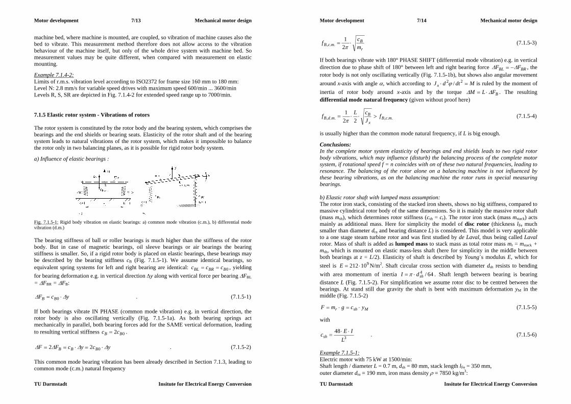
Motor development 7/13 Mechanical motor design
TU Darmstadt Insitute for Electrical Energy Conversion
machine bed, where machine is mounted, are coupled, so vibration of machine causes also the bed to vibrate. This measurement method therefore does not allow access to the vibration behaviour of the machine itself, but only of the whole drive system with machine bed. So measurement values may be quite different, when compared with measurement on elastic mounting. Example 7.1.4-2: Limits of r.m.s. vibration level according to ISO2372 for frame size 160 mm to 180 mm: Level N: 2.8 mm/s for variable speed drives with maximum speed 600/min ... 3600/min Levels R, S, SR are depicted in Fig. 7.1.4-2 for extended speed range up to 7000/min. 7.1.5 Elastic rotor system - Vibrations of rotors The rotor system is constituted by the rotor body and the bearing system, which comprises the bearings and the end shields or bearing seats. Elasticity of the rotor shaft and of the bearing system leads to natural vibrations of the rotor system, which makes it impossible to balance the rotor only in two balancing planes, as it is possible for rigid rotor body system. a) Influence of elastic bearings :
Fig. 7.1.5-1: Rigid body vibration on elastic bearings: a) common mode vibration (c.m.), b) differential mode vibration (d.m.) The bearing stiffness of ball or roller bearings is much higher than the stiffness of the rotor body. But in case of magnetic bearings, oil sleeve bearings or air bearings the bearing stiffness is smaller. So, if a rigid rotor body is placed on elastic bearings, these bearings may be described by the bearing stiffness cB (Fig. 7.1.5-1). We assume identical bearings, so equivalent spring systems for left and right bearing are identical: 0BBRBL ccc , yielding for bearing deformation e.g. in vertical direction y along with vertical force per bearing FBL = FBR = FB:
ycF BB 0 . (7.1.5-1) If both bearings vibrate IN PHASE (common mode vibration) e.g. in vertical direction, the rotor body is also oscillating vertically (Fig. 7.1.5-1a). As both bearing springs act mechanically in parallel, both bearing forces add for the SAME vertical deformation, leading to resulting vertical stiffness 02 BB cc .
ycycFF BBB 022 . (7.1.5-2) This common mode bearing vibration has been already described in Section 7.1.3, leading to common mode (c.m.) natural frequency
Motor development 7/14 Mechanical motor design
TU Darmstadt Insitute for Electrical Energy Conversion
r
BmcB m
cf 21
.., (7.1.5-3)
If both bearings vibrate with 180° PHASE SHIFT (differential mode vibration) e.g. in vertical direction due to phase shift of 180° between left and right bearing force BRBL FF , the rotor body is not only oscillating vertically (Fig. 7.1.5-1b), but shows also angular movement around x-axis with angle , which according to MdtdJx 22 / is ruled by the moment of inertia of rotor body around x-axis and by the torque BFLM . The resulting differential mode natural frequency (given without proof here)
..,.., 221
mcBx
BmdB f
JcLf
(7.1.5-4)
is usually higher than the common mode natural frequency, if L is big enough. Conclusions: In the complete motor system elasticity of bearings and end shields leads to two rigid rotor body vibrations, which may influence (disturb) the balancing process of the complete motor system, if rotational speed f = n coincides with on of these two natural frequencies, leading to resonance. The balancing of the rotor alone on a balancing machine is not influenced by these bearing vibrations, as on the balancing machine the rotor runs in special measuring bearings. b) Elastic rotor shaft with lumped mass assumption: The rotor iron stack, consisting of the stacked iron sheets, shows no big stiffness, compared to massive cylindrical rotor body of the same dimensions. So it is mainly the massive rotor shaft (mass msh), which determines rotor stiffness (csh = cr). The rotor iron stack (mass mstack) acts mainly as additional mass. Here for simplicity the model of disc rotor (thickness lFe much smaller than diameter dra and bearing distance L) is considered. This model is very applicable to a one stage steam turbine rotor and was first studied by de Laval, thus being called Laval rotor. Mass of shaft is added as lumped mass to stack mass as total rotor mass mr = mstack + msh, which is mounted on elastic mass-less shaft (here for simplicity in the middle between both bearings at z = L/2). Elasticity of shaft is described by Young´s modulus E, which for steel is 910212 E N/m2. Shaft circular cross section with diameter dsh resists to bending with area momentum of inertia 64/4
shdI . Shaft length between bearing is bearing distance L (Fig. 7.1.5-2). For simplification we assume rotor disc to be centred between the bearings. At stand still due gravity the shaft is bent with maximum deformation yM in the middle (Fig. 7.1.5-2)
Mshr ycgmF (7.1.5-5) with
348
LIEcsh
. (7.1.5-6)
Example 7.1.5-1: Electric motor with 75 kW at 1500/min: Shaft length / diameter L = 0.7 m, dsh = 80 mm, stack length lFe = 350 mm, outer diameter dra = 190 mm, iron mass density = 7850 kg/m3:

Motor development 7/15 Mechanical motor design
TU Darmstadt Insitute for Electrical Energy Conversion
6.274/2 shsh dLm kg, 1.644/)( 22 shraFestack ddlm kg,
7.911.646.27 rm kg, 64 1001.264/ shdI m4, 63 1063.5948
L
IEcsh N/m
Static rotor bending due to gravity: 15/ shrM cgmy m
Fig. 7.1.5-2: Disc rotor on elastic shaft (Laval rotor) Natural bending frequency is given by
0 ycym shr (7.1.5-7) with natural bending frequency
r
shb m
cf 21 . (7.1.5-8)
Conclusions: For getting stiff rotor the distance between the bearings must be small and the shaft diameter should be big. This and small rotor mass allow increase of rotor bending natural frequency. Example 7.1.5-2: Electric motor with 75 kW at 1500/min (Date of Example 7.1.5-1):
7.91rm kg, 61063.59 shc N/m
Natural bending frequency is 3.1287.91
5963195321
21
r
shb m
cf Hz
At speed n = fb = 7700/min an imbalance will excite big motor vibrations due to resonance. Therefore maximum motor speed should stay below 7.0max bfn 5390/min. c) Elastic rotor shaft with distributed mass: In reality the shaft has to be considered as cylindrical beam of diameter dsh and length L with DISTRIBUTED mass along the beam. Like a vibrating guitar string, this beam has not only one bending natural frequency, but a whole spectrum of natural bending modes, which depend on the elasticity of the bearings. Assuming rigid bearings, where the x- and y-co-ordinate of the beam is always zero, but allowing the beam to change its inclination also at the bearing´s location, the natural bending frequencies of the beam (with cross section areas A) are derived as
...,3,2,1,21 2
,
i
AIE
Lif ib
(7.1.5-9)
Motor development 7/16 Mechanical motor design
TU Darmstadt Insitute for Electrical Energy Conversion
As the iron stack mass increases the total mass, this considered according to (7.1.5-8) by
...,3,2,1,1
1,,,
i
mm
ff
sh
stackibcorrib (7.1.5-10)
Fig. 7.1.5-3: Model of shaft as cylindrical beam, showing a spectrum of bending natural frequencies, which depend on the influence of bearing stiffness Example 7.1.5-3: Electric motor with 75 kW at 1500/min (data of Example 7.1.5-1) : L = 0.7 m, dsh = 80 mm, = 7850 kg/m3, 6.27shm kg, 1.64stackm kg,
32.36.27/1.641/1 shstack mm , 32 1003.54/ shdA m2
i 1 2 3 fb,i,corr / Hz 182 731 1645
Compared with the simplified lumped mass model (7.1.5-6), the more detailed model (7.1.5-10) yields 40% higher first natural bending frequency and in addition also higher frequency eigen-modes. Bigger motors have rather big distance of bearings L and rather big rotor mass. Hence, to consider influence of machine size on natural bending frequency, we take geometric dimensions xdxL sh ~,~ in (7.1.5-9), showing that frequency decreases inverse with increasing frame size: xf ib /1~, . Conclusions: Calculation of natural bending frequency is rather complicated, as distributed mass and geometry of rotor has to be considered. The stiffening influence of rotor iron stack is also difficult to calculate. Elasticity of bearings may reduce the natural bending frequencies by about 10 % to 20 %. Further, big machines have low natural bending frequency. d) Influence of “unbalanced magnetic pull” on natural bending frequency: When the rotor shaft is bent by y, this leads to an air gap eccentricity e = -y . The electric machine air gap is reduced on side by e and increased on the other side by e . Thus radial magnetic flux density, which is excited by m.m.f. in air gap V , in case of machines with pole numbers 42 p is increased on side by )/(0 eVB and reduced on the opposite side by )/(0 eVB . Thus radial magnetic pull per unit rotor surface
Fepr lpA 2 with /0 VB as air gap flux density amplitude of non-eccentric rotor

Motor development 7/17 Mechanical motor design
TU Darmstadt Insitute for Electrical Energy Conversion
0
2
0
2
22
BfBf nn (7.1.5-11)
is no longer in equilibrium, but residual (“unbalanced”) magnetic pull in direction of decreased air gap remains (formula given without proof):
eB
lpAffF Fep
rnnM
2
02)( , 2p 4 (7.1.5-12)
For two-pole machines this unbalanced magnetic pull is only 50%. Note: At zero eccentricity e = 0 this residual pull is also zero.
Fig. 7.1.5-4: “Unbalanced magnetic pull” FM in four pole motor due to air gap eccentricity e This residual radial magnetic force tends to decrease the reduced air gap further. Comparing with the elastic bending of the shaft, where a bending by value y increases elastic force
ycF shcsh , acting against the bending force, the unbalanced magnetic pull acts in direction
of bending force, thus opposite to elastic force:
ycF MM . (7.1.5-13) Considering y = -e, the "magnetic stiffness"
1
22
0
B
lpc Fep
M (7.1.5-14)
has to be considered in the model of elastic rotor. It reduces the resulting stiffness by
Mshres ccc , (7.1.5-15) leading to decrease of natural bending frequency by
sh
Mb
r
MshMb c
cfm
ccf
121
, . (7.1.5-16)
Example 7.1.5-4: 4-pole electric motor with 75 kW at 1500/min (data of example 7.1.5-3): L = 0.7 m, dsh = 80 mm, lFe = 350 mm, dra = 190 mm, 7.91rm kg , air gap flux density amplitude B = 0.9 T, air gap = 1.0 mm, pole pitch: 149p mm
Motor development 7/18 Mechanical motor design
TU Darmstadt Insitute for Electrical Energy Conversion
Rotor gravity force: 900 gmr N Unbalanced magnetic pull at 10% eccentricity: 1.0/ e :
33601.09.01042
35.0149.022
27
2
0
eB
lpF Fep
M N
Depending on air gap eccentricity, the unbalanced magnetic pull can reach considerable values (here: 225 % of rotor gravity force). Calculated first natural bending frequency without influence of magnetic pull: 1831 bf Hz:
equivalent shaft stiffness: 621 104.121)2( rbsh mfc N/m,
magnetic stiffness: 62
0106.331
2
Blp
c FepM N/m
Calculated first natural bending frequency with influence of unbalanced magnetic pull: 6.1554.121/6.331183/11,1 shMbMb ccff Hz:
Conclusions: Unbalanced magnetic pull leads to a considerable decrease of natural bending frequency by about 10% ... 20%, depending on utilization of magnetic circuit. 7.1.6 Balancing of elastic rotors
Fig. 7.1.6-1: Static imbalance due to dislocation of centre of gravity S by eS from rotational axis. Additional dislocation of centre of rotation from geometrical axis of unbent shaft (here: Example of disc rotor on elastic shaft (Laval rotor)) We assume static imbalance due to dislocation of centre of gravity S by eS from rotational axis (Fig. 7.1.6-1). Neglecting the bending due to gravity, we here consider only bending due to centrifugal force caused by imbalance, which causes in y-direction additional dislocation yM of centre of rotation M from geometrical axis of unbent shaft. In x-direction dislocation xM
occurs. With resulting radial dislocation 22MMM yxr due to bending the centre of
gravity is displaced from geometrical axis by MSS rer , causing centrifugal force
22)( mSrmMSrS rmremF . (7.1.6-1) The shaft bends until equilibrium between centrifugal force and elastic force is reached,
MshmMSrcS rcremFFsh
2)( , (7.1.6-2)

Motor development 7/19 Mechanical motor design
TU Darmstadt Insitute for Electrical Energy Conversion
yielding for the displacement rM of centre of rotation M from geometrical axis in dependence of speed
22
2
mb
mSM er
, bb f 2 (7.1.6-3)
and for the displacement rS of centre of gravity S from geometrical axis in dependence of speed (Fig. 7.1.6-2)
22
2
mb
bSS er
. (7.1.6-4)
Fig. 7.1.6-2: Displacement rS of centre of gravity S from geometrical axis in dependence of speed After passing through the resonance region, the centre of gravity is centring itself on the geometrical axis at high speed ( 0Sr ); hence the centrifugal force will vanish at high
speed. Centrifugal force is depending not only on US and 2m , but also on the ratio of
bm / , so rigid body balancing is not possible any longer.
22
222
2
)/(11
mbm
Smmb
bSrS UemF
(7.1.6-5)
In order to minimize the increase of centrifugal force and the related bearing forces
)sin(2/
)cos(2/
~,~,
~,~,
tFFF
tFFF
mSyByA
mSxBxA
(7.1.6-6)
near resonance bm , special balancing techniques for elastic rotors have been developed. In a third plane additional balancing masses are fixed. This third plane should be located at the rotor near the location of maximum rotor bending. The centrifugal force of this added imbalance shall act opposite to the centrifugal force of the bent shaft. Small and medium sized motors are operated even with high speed application usually below first natural bending frequency. So the rigid body balancing is sufficient. But bigger motors
Motor development 7/20 Mechanical motor design
TU Darmstadt Insitute for Electrical Energy Conversion
have their first natural bending frequency already below their rated speed, so elastic balancing is necessary. Big 2-pole turbo generators for steam power plants with bearing distances L of several meters, being operated at 3000/min = 50 Hz, have typically 2 or 3 natural bending frequencies below 50 Hz. Elastic balancing needs for each natural bending frequency, which is below maximum machine operating speed, an additional balancing plane to fix further balancing masses. The centrifugal forces of these added imbalances shall counter-act to the bending modes of the rotor at each of the natural bending frequencies. Example 7.1.6-1: a) 2-pole standard induction motor, 50 Hz, 500 kW: 1st natural bending frequency at fb1 = 35 Hz. Elastic balancing with 3 balancing planes is necessary. b) 2-pole large synchronous turbo generator, 50 Hz, 1000 MW (power plant Lippendorf, Germany): 3 natural bending frequencies lie in the frequency range 5 ... 40 Hz: Elastic balancing with 5 balancing planes is necessary.

Motor development 8/1 Stepper motors
TU Darmstadt Institute for Electrical Energy Conversion
8. Stepper motors Electromechanical actuators, which transform electrical impulses into mechanical steps, are called stepper motors. A complete stepper drive consists of - an electronic control unit, - a power amplifier, including a grid-side front end, and - a stepper motor.
Fig. 8-1: Basic scheme of a stepper drive (Stölting et al., El. Kleinmaschinen, Teubner, 1987) In order to keep the cost for a stepper drive as low as possible, the stepper motor is operated in a feed forward control, without any use of a position feed-back. Hence the condition, that the number of electrical impulses is always identical with the number of mechanical steps, must be guaranteed under all circumstances. Stepper motors usually operate according to the synchronous motor principle in three different variants (Table 8-1): - Variable reluctance stepper motors (VR-motor) - Permanent magnet stepper motors (PM-motor) - Hybrid stepper motors, which operate on a combination of the PM and VR stepper
principle Therefore stepper motors, like grid-operated synchronous motors, have a static pull-out torque, which is the maximum available electromagnetic torque at steady state operation. If the load torque at the shaft is bigger than the pull-out torque, the rotor is pulled out of synchronism and falls behind the stator magnetic field; the motor is losing steps. During acceleration and deceleration the rotor tends to oscillate like grid-operated synchronous machines due to the elastic attributes of the magnetic field forces and the rotor and load inertia. Hence stepper motors are usually manufactured only up to a rated power of about 1 kW. For bigger power the position-controlled synchronous servo drives („brushless DC drives“), which are not endangered by pull-out torque and intrinsic oscillation, are the more economical solution. Type of stepper motor PM-motor VR-motor Hybrid motor Electromagnetic utilization high low medium Damping of oscillations good bad good Detent torque (= at open circuit) ? yes no yes Minimum necessary phase count 2 3 2 Cost low high high Table 8-1: Three variants of stepper motor principles
Electronic supply unit Motor
Input steps
Impulse program Switching program
Micro processor
control
Grid input
Motor development 8/2 Stepper motors
TU Darmstadt Institute for Electrical Energy Conversion
8.1 Basic principle of operation of steppers The multi-phase stator winding may be arranged in the stepper motors either - in one plane (Fig. 8.1-1a) or - in different planes along the rotating axis (Fig. 8.1-1b).
a) b) Fig. 8.1-1: Design examples of the multi-phase stator winding of a VR-motor with m phases and Qr rotor teeth a) stator winding phases in one plane: m = 3, Qr = 2 b) stator winding phases in three planes along the axis: m = 3, Qr = 4 We assume that each stator phase is fed independently by an impulse voltage, so each phase is energized separately. If the feeding leads to block currents (impulses) per phase, the stator magnetic field is directed into the axis of phase U, if phase U is energized only. A PM rotor of the same pole count as the stator winding or a reluctance rotor of Qr/p = 2 rotor teeth per pole pair (like a conventional synchronous reluctance machine) will be aligned into the stator field direction due to the magnetic tangential drag. By feeding afterwards phase W with a negative block current (bipolar feeding) the stator field performs a step of 60°el., which the above described rotors will follow due to the magnetic tangential drag. In case of uni-polar feeding (= always positive phase current) the next phase to be energized may e.g. phase V, which is shifted spatially by 1/3 of 2p to phase U. Hence the stator field will make a step of 120°el.. A PM will have to move also by 120°, whereas the VR rotor moves only by 60°, because it is magnetized in the opposite direction and aligns like that into the direction of phase V. Energizing next phase W with positive phase current moves the PM rotor by another 120°, and the VR rotor by another 60°, being now magnetized again into the same direction as before in case of phase U. According to Fig. 8.1-1a the number of mechanical steps zp during one stator period Ts = 1/fs for a VR-rotor is given with m stator phases and Qr/p rotor teeth per pole pair as
mpQz rp )/( (8.1-1) At each step the rotor is shifted by the rated stepping angle (in electrical degrees, as a shift by 2 is a movement per one pole pair)
pe z/2 . (8.1-2) The number of steps per rotor revolution is p-times bigger:
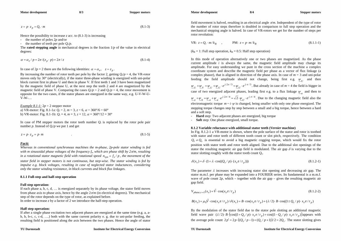
Motor development 8/3 Stepper motors
TU Darmstadt Institute for Electrical Energy Conversion
mQzpz rp (8.1-3)
Hence the possibility to increase z acc. to (8.1-3) is increasing - the number of poles 2p and/or - the number of teeth per pole Qr/p. The rated stepping angle in mechanical degrees is the fraction 1/p of the value in electrical degrees:
zpzp pe /2)/(2/ . (8.1-4) In case of 2p = 2 there are the following identities: pe zz , . By increasing the number of rotor teeth per pole by the factor 2, getting Qr/p = 4, the VR-rotor moves only by 30° (electrically), if the stator three-phase winding is energized with uni-polar block current first in phase U and then in phase V. If first teeth 1 and 3 have been magnetized by the magnetic field of phase U, at the next step the teeth 2 and 4 are magnetized by the magnetic field of phase V. Comparing the cases Qr/p = 2 and Qr/p = 4, the rotor movement is opposite for the two cases, if the stator phases are energized in the same way, e.g. U-V-W-U-V-W-… Example 8.1-1: 2p = 2 stepper motor a) VR-motor: Fig. 8.1-1a: Qr = 2, m = 3, z = 6, = 360°/6 = 60° b) VR-motor: Fig. 8.1-1b: Qr = 4, m = 3, z = 12, = 360°/12 = 30° In case of PM stepper motors the rotor teeth number Qr is replaced by the rotor pole pair number p. Instead of Qr/p we put 1 and get
mpzpz p . (8.1-5) Facit: Whereas in conventional synchronous machines the m-phase, 2p-pole stator winding is fed with m sinusoidal phase voltages of the frequency fs, which are phase shift by 2/m, resulting in a rotational stator magnetic field with rotational speed pfn ssyn / , the movement of the stator field in stepper motors is not continuous, but step-wise. The stator winding is fed by impulse e.g. block voltages, resulting in case of neglected stator inductances, considering only the stator winding resistance, in block currents and block flux linkages. 8.1.1 Full-step and half-step operation Full step operation: If each phase a, b, c, d, … is energized separately by its phase voltage, the stator field moves from phase axis to phase axis, hence by the angle 2/m (in electrical degrees). The mechanical step of the rotor depends on the type of rotor, as explained before. In order to increase z by a factor of 2 we introduce the half-step operation. Half step operation: If after a single phase excitation two adjacent phases are energized at the same time (e.g. a, a-b, b, b-c, c, c-d, ….) both with the same current polarity e. g. due to uni-polar feeding, the resulting field is positioned along the axis between the two phases. Hence the angle of stator
Motor development 8/4 Stepper motors
TU Darmstadt Institute for Electrical Energy Conversion
field movement is halved, resulting in an electrical angle /m. Independent of the type of rotor the number of rotor steps therefore is doubled in comparison to full step operation and the mechanical stepping angle is halved. In case of VR-rotors we get for the number of steps per rotor revolution: VR: Br kmQz / , PM: Bkmpz / (8.1.1-1) (kB = 1: Full step operation, kB = 0.5: Half step operation) In this mode of operation alternatively one or two phases are magnetized. As the phase current amplitude i is always the same, the magnetic field amplitude may change its amplitude. For easy understanding we punt in the cross section of the machine a complex coordinate system and describe the magnetic field per phase as a vector of flux linkage (a complex phasor), that is aligned in direction of the phase axis. In case of m = 3 and uni-polar feeding the field amplitude should not change, being first e.g. U and then
3/3/2 jU
jUUVU ee . But already in case of m = 4 the field is bigger in
case of two energized adjacent phases, leading first e.g. to a flux linkage a and then to 4/4/2 2 j
Uj
aaba ee . Due to the changing magnetic field also the electromagnetic torque im ~ is changed, being smaller with only one phase energized. The stepping torque changes step by step between a small and a big torque, hence between a hard and a soft step. - Hard step: Two adjacent phases are energized, big torque - Soft step: One phase energized, small torque. 8.1.2 Variable reluctance with additional stator teeth (Vernier machine) In Fig. 8.1.2-1 a VR-motor is shown, where the pole surface of the stator and rotor is toothed with stator and rotor teeth of different tooth count or slot pitch, respectively. The condition
sr QQ is essential to avoid a big magnetic cogging torque, which would fix the rotor position with stator teeth and rotor teeth aligned. Due to the additional slot openings of the stator the resulting magnetic air gap field is modulated. The air gap is varying due to the stator slotting roughly with the stator tooth count Qs.
)))/()/cos((1()( psss xpQx (8.1.2-1) The parameter increases with increasing stator slot opening and decreasing air gap. The stator m.m.f. per phase may be expanded into a FOURIER series. Its fundamental is a m.m.f. wave of pole count 2p, which – together with the air gap – gives the resulting magnetic air gap field.
)/cos(ˆ)(1, pssphase xVxV (8.1.2-2)
)/)/1cos(()2/()/cos()(/)/cos(ˆ)( 0 psspsspss xpQBxBxxVxB By the modulation of the stator field due to the stator pole slotting an additional magnetic field wave pair )/)/1cos(()/)/1cos(()2/( psspss xpQxpQB appears with the average pole count sss QpQpQpp 22/)1/()1/(22 . The stator slotting gives

Motor development 8/5 Stepper motors
TU Darmstadt Institute for Electrical Energy Conversion
by modulation of the stator field an additional harmonic field wave of the pole count sQp 22 . The rotor teeth are interacting with this space harmonic field wave and experience
a much higher pole count pQp s 222 , which now defines the number of steps per revolution. Hence the rotor teeth per pole pQr / are of interest to define the number of mechanical steps zp during one stator period T = 1/fs for a VR-rotor. Therefore the number of rotor teeth must be refined with respect to the number of stator teeth. With m stator phases and Qr/p´ rotor teeth per “new” pole pair the number of steps per electrical period is mpQz rp )/( . The number of steps per rotor revolution is p´-times bigger, resulting again in mQzpz rp (Vernier principle), but now with a much bigger number of rotor teeth with small slot openings and small slot depth. Facit: The stator slotting gives by modulation of the stator field an additional harmonic field wave of the pole count sQp 22 . The rotor teeth are interacting with this space harmonic field wave and experience a much higher pole count pQp s 222 , which now defines the number of steps per revolution.
a) Phase 1 energized b) Phase 2 energized Fig. 8.1.2-1: 2-pole VR-motor with stator and rotor slotting: Qs = 8, Qr = 9, m = 4 Example 8.1.2-1: Vernier VR-motor acc. to Fig. 8.1.2-1: 2p = 2, Qs = 8, Qr = 9, m = 4:
1622 sQp , 8/9/ pQr , 2/94)8/9()/( mpQz rp 3649)2/9(8 mQzpz rp , = 360°/36 = 10°
8.1.3 Comparison of basic stepper motor functionality VR stepper motors: According to Chapter 2 a switched reluctance motor, which is the special case of a VR-motor with position encoder feed back, cannot self-start, if it is only manufactured with 2 phases and symmetrical rotor. In order to get a defined direction of self-starting, at minimum three phases are necessary. In open circuit (= zero stator current) the torque is zero. Hence at switched off motor no torque is supplied to keep the motor in the wanted position. On the other hand a very fine slotting can be manufactured with problems, so with the Vernier principle a rather high number of steps per revolution is possible. PM stepper motors: PM-motors have due to the rotor permanent magnet field also in 2-phase stators a defined starting torque and starting direction, so the minimum phase number for stepper operation is 2. At open circuit the cogging torque of the rotor permanent magnet field with the stator
Motor development 8/6 Stepper motors
TU Darmstadt Institute for Electrical Energy Conversion
slotting provides sufficient torque to keep the rotor at the desired position before switch-off. On the other hand it is very difficult to magnetize a cylindrical rotor permanent magnet material with a high pole count, as the magnetization coils for a N-S-N-S-polarization with a very small pole width are difficult manufacture. Hence the number of steps per revolution is considerably smaller than in VR-motors. So rotors for a high number of steps per revolution must be VR-rotors with a very accurate manufacturing in order to keep the relative error of the individual stepping angle below 3% ... 5%. Hybrid stepper motors: In hybrid motors a rotor PM excitation is combined with toothed rotor ring structures to generate a variable reluctance in the air gap. Hence the advantages of PM stepper motors with minimum phase count 2 and open circuit torque are combined with the advantages of VR stepper motors with a high number of steps per revolution (Table 8.1-3-1). type of motor VR/H VR/H VR/H VR/H/PM PM PM PM PM PM rotor teeth Qr 100 90 50 24 rotor poles 2p 24 20 16 12 6 4 z (at m = 2) 200 180 100 48 40 32 24 12 8 / ° (mech.) 1.8 2 3.6 7.5 9 11.25 15 30 45 Table 8.1.3-1: Typical numbers of rotor teeth for different kinds of stepper motors (VR: variable reluctance stepper motor, H: hybrid stepper motor, PM: permanent magnet stepper motor) 8.1.4 Micro stepping If the stator winding of the 3-phase, 2-pole VR-motor with 2 rotor teeth of Fig. 8.1-1a is fed with uni-polar phase currents according to Fig. 8.1.4-1, the rotor will need for one revolution two electrical periods 2Ts and will perform six steps per revolution. During one electrical period the rotor performs 3 mechanical steps. Electrical stator frequency fs = 1/Ts, stepping frequency f = 1/T = 3fs By applying a bipolar current feeding with e.g. kz = 20 current steps per period Ts (Fig. 8.1.4-2), where the stepped current curve approximates a sine wave, the rotor will perform instead of 3 steps per period Ts now 20 “micro” steps. This can be understood easily, if the magnetic field per phase is regarded as a vector, which is aligned into positive phase axis, when fed with positive phase current. Due to Ampere´s law the length of the vector is directly proportional to the phase current, e.g. UU i~ . Hence the vector of the resulting magnetic field is a superposition of the phase magnetic field vectors. In a three-phase system (m = 3) the direction of the three phase axes is shifted in space by 120° (electrically). Hence the phase magnetic field vector of V is shifted with respect to U by 2/3 or 3/2 jea , and the phase
vector of W by 240° or 3/42 jea . The resulting magnetic field vector, expressed as the resulting magnetic flux linkage, is given as superposition of the three phase flux linkage vectors.
WVUWVU iaiai 2~ (8.1.4-1) Hence the position of the resulting field my be adjusted by the current values iU, iV, iW nearly continuously. If these values approximate a sine wave function with e.g. 20 steps per period 2/20, the resulting field will take 20 positions per period with almost constant amplitude .
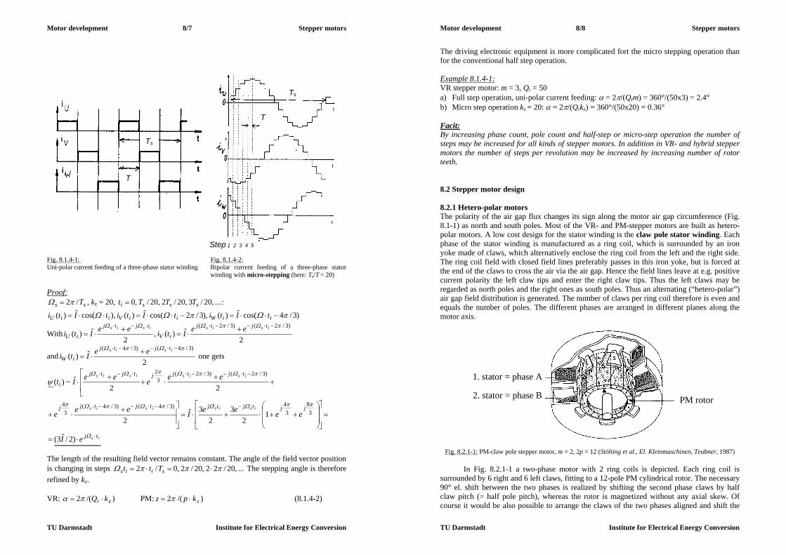
Motor development 8/7 Stepper motors
TU Darmstadt Institute for Electrical Energy Conversion
Fig. 8.1.4-1: Fig. 8.1.4-2: Uni-polar current feeding of a three-phase stator winding Bipolar current feeding of a three-phase stator
winding with micro-stepping (here: Ts/T = 20) Proof:
ss T/2 , kz = 20, ...,20/3,20/2,20/,0 sssi TTTt :
)3/4cos(ˆ)(),3/2cos(ˆ)(),cos(ˆ)( iiWiiViiU tItitItitIti
With2
ˆ)(,2
ˆ)()3/2()3/2(
isisisis tjtj
iV
tjtj
iUeeItieeIti
and2
ˆ)()3/4()3/4(
isis tjtj
iWeeIti one gets
is
isisisis
isisisis
tj
jjtjtjtjtjj
tjtjjtjtj
i
eI
eeeeIeee
eeeeeIt
)2/ˆ3(
12
32
3ˆ2
22ˆ~)(
38
34)3/4()3/4(
34
)3/2()3/2(3
2
The length of the resulting field vector remains constant. The angle of the field vector position is changing in steps ...,20/22,20/2,0/2 siis Ttt The stepping angle is therefore refined by kz. VR: )/(2 zr kQ PM: )/(2 zkpz (8.1.4-2)
T
Ts
t
t
t
Ts
T
Step 1 2 3 4 5
Motor development 8/8 Stepper motors
TU Darmstadt Institute for Electrical Energy Conversion
The driving electronic equipment is more complicated fort the micro stepping operation than for the conventional half step operation. Example 8.1.4-1: VR stepper motor: m = 3, Qr = 50 a) Full step operation, uni-polar current feeding: = 2/(Qrm) = 360°/(50x3) = 2.4° b) Micro step operation kz = 20: = 2/(Qrkz) = 360°/(50x20) = 0.36°
Facit: By increasing phase count, pole count and half-step or micro-step operation the number of steps may be increased for all kinds of stepper motors. In addition in VR- and hybrid stepper motors the number of steps per revolution may be increased by increasing number of rotor teeth. 8.2 Stepper motor design 8.2.1 Hetero-polar motors The polarity of the air gap flux changes its sign along the motor air gap circumference (Fig. 8.1-1) as north and south poles. Most of the VR- and PM-stepper motors are built as hetero-polar motors. A low cost design for the stator winding is the claw pole stator winding. Each phase of the stator winding is manufactured as a ring coil, which is surrounded by an iron yoke made of claws, which alternatively enclose the ring coil from the left and the right side. The ring coil field with closed field lines preferably passes in this iron yoke, but is forced at the end of the claws to cross the air via the air gap. Hence the field lines leave at e.g. positive current polarity the left claw tips and enter the right claw tips. Thus the left claws may be regarded as north poles and the right ones as south poles. Thus an alternating (“hetero-polar”) air gap field distribution is generated. The number of claws per ring coil therefore is even and equals the number of poles. The different phases are arranged in different planes along the motor axis.
Fig. 8.2.1-1: PM-claw pole stepper motor, m = 2, 2p = 12 (Stölting et al., El. Kleinmaschinen, Teubner, 1987)
In Fig. 8.2.1-1 a two-phase motor with 2 ring coils is depicted. Each ring coil is surrounded by 6 right and 6 left claws, fitting to a 12-pole PM cylindrical rotor. The necessary 90° el. shift between the two phases is realized by shifting the second phase claws by half claw pitch (= half pole pitch), whereas the rotor is magnetized without any axial skew. Of course it would be also possible to arrange the claws of the two phases aligned and shift the
1. stator = phase A
2. stator = phase B PM rotor

Motor development 8/9 Stepper motors
TU Darmstadt Institute for Electrical Energy Conversion
rotor magnetization of the second half (beneath the second phase) by half pole pitch. But this kind of magnetization is difficult to realize and is therefore not in use.
Note, that this kind of motor very closely resembles to a two-phase transversal flux motor, where the stator U-yokes are replaced by the stator claws! Example 8.2.1-1: PM-claw pole stepper motor (Fig. 8.2.1-1): Number of steps per revolution z = 2p.m = 12x2 = 24, stepping angle = 360°/24 = 15° (mech. degrees) In Fig. 8.2.1-2 the bipolar current feeding for the two phases A and B is shown for the motor of Fig. 8.2.1-1 for full step operation step by step. The current polarity in A is reversed prior to the current in B. The direction of rotation is reversed by changing the sequence of current reversal; the current polarity in B is then reversed before the current in A changes its polarity. It is clearly visible, that two phases are sufficient in PM motors to define the direction of motion at starting.
Fig. 8.2.1-2: Current feeding sequence of a two-phase claw pole PM stepper motor 8.2.2 Homo-polar motors Rotor permanent magnets: The flux polarity does not change along the motor air gap circumference, but it is changing in axial direction. Hence the air gap flux density along the rotor circumference is called homo-polar. Mainly hybrid stepper motors are designed as homo-polar machines. In Fig. 8.2.2-1a the two-phase stator winding (m = 2) is unskewed. The permanent magnet rotor has at its outer side two additional toothed iron rings, which are shifted by half tooth pitch in circumference direction. The rotor shaft is made of non-magnetic iron to keep the permanent magnet inner stray flux as small as possible. The homo-polar permanent magnet flux leaves the first rotor half with positive polarity and enters the second half, hence defining there negative polarity. So all teeth of the first ring are north poles, and the teeth of the second ring are south poles. If the rotor magnet is omitted, only the iron tooth rings remain and we get a VR-motor in homo-polar design. For the same stator Ampere-turns this VR-motor produces a smaller torque than the hybrid stepper motor due to the missing PM flux.
1. stator – phase A
2. stator – phase B
PM rotor
1. stator – phase A with reversed current
2. stator – phase B with reversed current
Motor development 8/10 Stepper motors
TU Darmstadt Institute for Electrical Energy Conversion
a)
b) Fig. 8.2.2-1: 2-phase hybrid stepper motors with homo-polar flux arrangement and bipolar current operation: a) Permanent magnet in the rotor, 3 rotor teeth per half machine, 4 stator teeth (Stölting et al., El. Kleinmaschinen, Teubner, 1987), b) Permanent magnet in the stator, claw pole stator, 1 tooth in stator and rotor per radial plane: c: coil flux, PM: PM flux (Philips Comp.) The bipolar current operation for the stator winding of the motor of Fig. 8.2.2-1a is shown in Fig. 8.2.2-2 for
(i) full step operation with one excited stator phase, (ii) full step operation with two excited stator phases (increased torque), (iii) half step operation, exciting alternatively m = 2 and m - 1 = 1 phases.
Stator permanent magnets: In the same way the permanent magnet may be also arranged in the stator as e.g. a ring magnet with axial direction of magnetization to guide the flux PM with positive polarity in the first axial half of the machine (here: first phase) and with negative polarity in the second half (= second phase) (Fig. 8.2.2-1b, stator claw pole arrangement with one claw per half side (cup)). If the first phase is magnetized with positive current, resulting in a positive coil flux c, PM and c add on the left stator cup of phase 1 and substract on the right cup. Hence the rotor moves in aligned tooth position on the left cup (plane 1). For the next step phase 1 is switched off and phase 2 is magnetized (full step operation) e.g. with positive current,
iron back
South pole rotor teeth
Stator tooth
PM Non-magnetic
shaft
rotor
Stator winding
North pole rotor teeth

Motor development 8/11 Stepper motors
TU Darmstadt Institute for Electrical Energy Conversion
aligning stator and rotor tooth in plane 4, where PM and c add. A step of 90° is performed in counter-clockwise operation. Then phase 2 is turned off and phase 1 is energized with negative coil current. Due to negative c the fluxes PM and c add on the right stator cup of phase 1 (plane 2), where the teeth align. In total 2x90° =180° rotational angle have been performed. Then phase 2 is energized with negative current and so on.
(i) (ii) (iii) Fig. 8.2.2-2: Current pattern in the stator winding of the hybrid stepper motor of Fig. 8.2.2-1: full step operation with (i) one excited stator phase, (ii) with two excited stator phases, (iii) half step operation (Stölting et al., El. Kleinmaschinen, Teubner, 1987) Example 8.2.2-1: Hybrid stepper motor of Fig. 8.2.2-1a: m = 2. Sum of the teeth of both tooth rings: Qr = 6 kB = 1: Full step operation (Fig. 8.2.2-2 (i) and (ii): 12/ Br kmQz , = 360°/12 = 30° kB = 0.5: Half step operation: 24/ Br kmQz , = 360°/24 = 15° Example 8.2.2-2: Hybrid stepper motor of Fig. 8.2.2-1b: m = 2. Sum of the teeth of the two tooth rings per phase: Qr = 2 kB = 1: Full step operation: 4/ Br kmQz , = 360°/4 = 90° 8.2.3 Single phase stepper motors Single phase stepper motors are used e.g. as drives for watches and are very simple and low cost motors. They are PM stepper motors with a PM rotor and asymmetric stator poles (teeth) to define a direction of motion.
a) In Fig. 8.2.3-1 the single phase (m = 1) stator winding carries no current at the time instant a. The rotor is positioned according the cogging torque, which is generated by the PM rotor flux and the stator teeth.
b) At time instant b the stator coil is energized with positive current (voltage Uc), exciting a flux c. Hence the left pole shoe (tooth) is magnetized as north-pole and the right one as south-pole. Due to that magnet field the rotor is turned anti-clockwise.
Motor development 8/12 Stepper motors
TU Darmstadt Institute for Electrical Energy Conversion
c) At time instant c the current is again zero and the rotor is fixed due to the cogging torque.
d) At time instant d the stator winding is energized with reversed current (voltage –Uc), exciting a flux -c. The left pole shoe (tooth) is magnetized as south-pole and the right one as north-pole. Hence the rotor continues its anti-clockwise rotation.
Note: If the stator winding is energized at time instant b with negative current (left pole shoe is south-pole), the rotor would not have moved at all. Only positive current allows rotation, which shows that it is possible to get a defined sense of rotation also with single phase
Fig. 8.2.3-1: Single phase PM stepper motor with asymmetric poles by narrower air gap at one pole side (Stölting et al., El. Kleinmaschinen, Teubner, 1987) Facit: VR- and PM-stepper motors are mainly manufactured as hetero-polar motors, whereas hybrid steppers are mainly homo-polar machines. Single phase steppers need an asymmetric magnetic circuit and are manufactured as PM machines. 8.3 Driving circuits of stepper motors
Fig. 8.3-1: Driving circuits for stepper motors with a) uni-polar, b) bipolar current. Free-wheeling diodes are omitted here for clarity. The resistance Rv are used to reduce the electric time constant (Stölting et al., El. Kleinmaschinen, Teubner, 1987) a) The two branches A1, A2 of phase A and B1, B2 of phase B are energized subsequently always with positive
current, so always one branch per phase is without current, which gives only 50% motor winding utilization. b) By using four switches instead of two per phase the phases A and B may be energized with bi-polar current,
so always the complete phase winding is energized, yielding a high motor utilization at the expense of double amount of power switches.
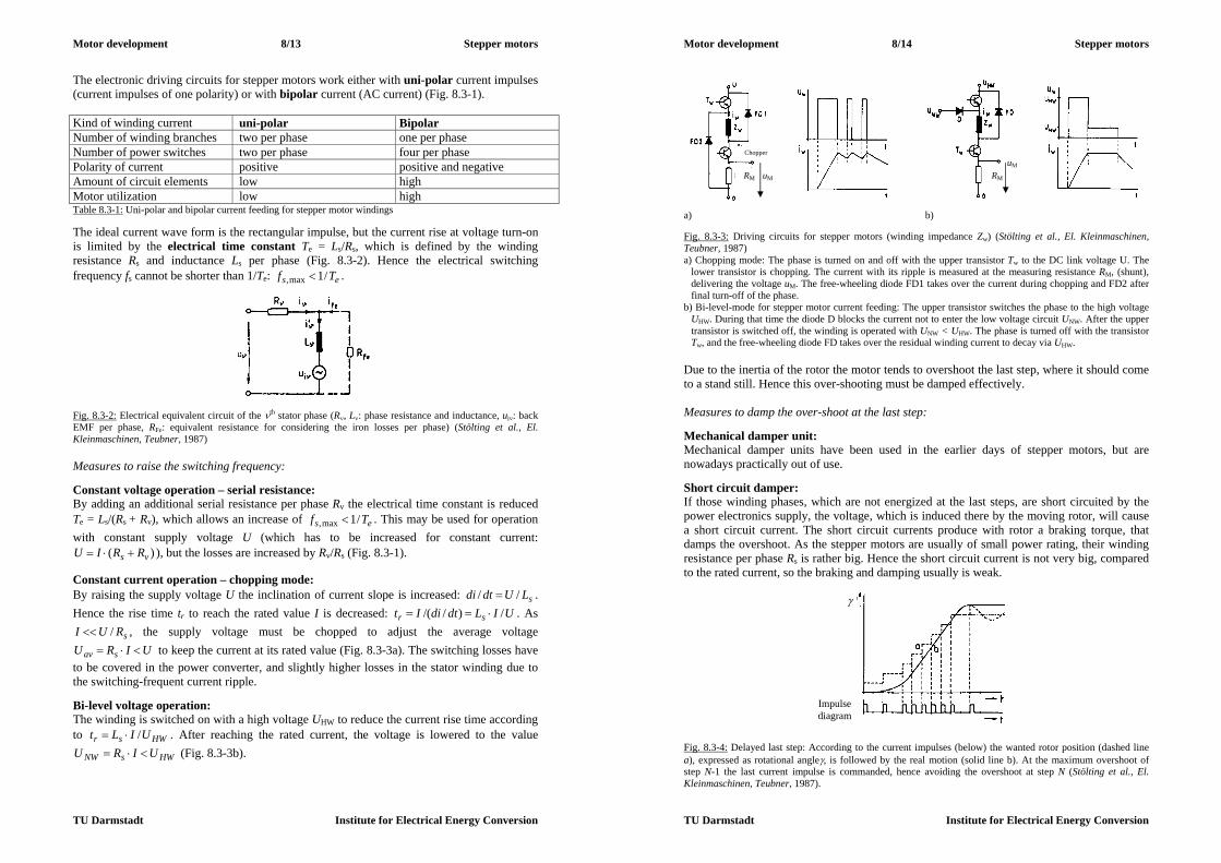
Motor development 8/13 Stepper motors
TU Darmstadt Institute for Electrical Energy Conversion
The electronic driving circuits for stepper motors work either with uni-polar current impulses (current impulses of one polarity) or with bipolar current (AC current) (Fig. 8.3-1). Kind of winding current uni-polar Bipolar Number of winding branches two per phase one per phase Number of power switches two per phase four per phase Polarity of current positive positive and negative Amount of circuit elements low high Motor utilization low high Table 8.3-1: Uni-polar and bipolar current feeding for stepper motor windings The ideal current wave form is the rectangular impulse, but the current rise at voltage turn-on is limited by the electrical time constant Te = Ls/Rs, which is defined by the winding resistance Rs and inductance Ls per phase (Fig. 8.3-2). Hence the electrical switching frequency fs cannot be shorter than 1/Te: es Tf /1max, .
Fig. 8.3-2: Electrical equivalent circuit of the th stator phase (R, L: phase resistance and inductance, ui: back EMF per phase, RFe: equivalent resistance for considering the iron losses per phase) (Stölting et al., El. Kleinmaschinen, Teubner, 1987) Measures to raise the switching frequency: Constant voltage operation – serial resistance: By adding an additional serial resistance per phase Rv the electrical time constant is reduced Te = Ls/(Rs + Rv), which allows an increase of es Tf /1max, . This may be used for operation with constant supply voltage U (which has to be increased for constant current:
)( vs RRIU ), but the losses are increased by Rv/Rs (Fig. 8.3-1). Constant current operation – chopping mode: By raising the supply voltage U the inclination of current slope is increased: sLUdtdi // . Hence the rise time tr to reach the rated value I is decreased: UILdtdiIt sr /)//( . As
sRUI / , the supply voltage must be chopped to adjust the average voltage UIRU sav to keep the current at its rated value (Fig. 8.3-3a). The switching losses have
to be covered in the power converter, and slightly higher losses in the stator winding due to the switching-frequent current ripple. Bi-level voltage operation: The winding is switched on with a high voltage UHW to reduce the current rise time according to HWsr UILt / . After reaching the rated current, the voltage is lowered to the value
HWsNW UIRU (Fig. 8.3-3b).
Motor development 8/14 Stepper motors
TU Darmstadt Institute for Electrical Energy Conversion
a) b) Fig. 8.3-3: Driving circuits for stepper motors (winding impedance Zw) (Stölting et al., El. Kleinmaschinen, Teubner, 1987) a) Chopping mode: The phase is turned on and off with the upper transistor Tw to the DC link voltage U. The
lower transistor is chopping. The current with its ripple is measured at the measuring resistance RM, (shunt), delivering the voltage uM. The free-wheeling diode FD1 takes over the current during chopping and FD2 after final turn-off of the phase.
b) Bi-level-mode for stepper motor current feeding: The upper transistor switches the phase to the high voltage UHW. During that time the diode D blocks the current not to enter the low voltage circuit UNW. After the upper transistor is switched off, the winding is operated with UNW < UHW. The phase is turned off with the transistor Tw, and the free-wheeling diode FD takes over the residual winding current to decay via UHW.
Due to the inertia of the rotor the motor tends to overshoot the last step, where it should come to a stand still. Hence this over-shooting must be damped effectively. Measures to damp the over-shoot at the last step: Mechanical damper unit: Mechanical damper units have been used in the earlier days of stepper motors, but are nowadays practically out of use. Short circuit damper: If those winding phases, which are not energized at the last steps, are short circuited by the power electronics supply, the voltage, which is induced there by the moving rotor, will cause a short circuit current. The short circuit currents produce with rotor a braking torque, that damps the overshoot. As the stepper motors are usually of small power rating, their winding resistance per phase Rs is rather big. Hence the short circuit current is not very big, compared to the rated current, so the braking and damping usually is weak.
Fig. 8.3-4: Delayed last step: According to the current impulses (below) the wanted rotor position (dashed line a), expressed as rotational angle, is followed by the real motion (solid line b). At the maximum overshoot of step N-1 the last current impulse is commanded, hence avoiding the overshoot at step N (Stölting et al., El. Kleinmaschinen, Teubner, 1987).
Chopper
uM
RM uM RM
Impulse diagram

Motor development 8/15 Stepper motors
TU Darmstadt Institute for Electrical Energy Conversion
Electronic damping: a) Delayed last step: If the current impulse for the last step is given delayed during the maximum overshoot of the step before, the rotor will have lost already a part of its kinetic energy and will come to rest without further overshoot (Fig. 8.3-4). b) Back phase damping: The final step N+1 is a step into opposite direction of motion to brake the rotor at the step N. Facit: Uni-polar and bipolar impulse current feeding is used to operate the stepper motors stepwise, but always in open-loop. The drive unit must avoid overshoot at the last step and should be able to realize high switching frequencies. 8.4 Torque characteristics of stepper motors 8.4.1 Static torque characteristic Like in conventional feed-forward operated synchronous machines, operated by voltage supply, there exist two kinds of static torque components:
a) synchronous torque Msyn (interaction of rotor magnetic field with stator current in the stator winding),
b) reluctance torque Mrel (interaction of stator magnetic field of stator currents, which is modulated by rotor reluctance, with stator currents in the stator winding).
Cogging torque: In Fig. 8.4.1-1 for a PM-stepper motor the synchronous torque due to the interaction of the rotor PM field with the stator currents is depicted. The reluctance torque in this case is given by the interaction of the rotor PM field with its modulated field component due to the stator slotting. This cogging torque occurs already at no load (= stator open circuit) and is an unwanted effect. The resulting torque of the PM stepper motor is therefore a superposition of both torque components. The stator field is not modulated by the rotor, as the rare earth rotor PM material has a permeability of nearly unity, so there is no rotor reluctance active for the stator field. Holding torque MH: The holding torque is the maximum torque, with which an excited stepper motor can be loaded without performing a continuous motion. In Fig. 8.4.1-1 this torque corresponds with the static pull out torque Mp0 of an electrically excited synchronous machine, which occurs at a load angle of ±90° (el.). The disturbing influence of the cogging torque increases MH slightly and shifts this value to 90 . If the stator slot openings are small, this influence may be neglected. Detent torque MD: The detent torque is the maximum torque, with which an un-excited stepper motor can be loaded without performing a continuous motion. Like in Fig. 8.4.1-1, this torque corresponds in PM and hybrid stepper motors with the cogging torque. The stable operation range for PM stepper motors without VR or cogging effect is given as
9090 (Fig. 8.4.1-2a). In VR motors only the reluctance torque Mrel exists, when the stator winding is excited. This torque is essentially determined by rotor slot width and depth. No detent torque exists.
Motor development 8/16 Stepper motors
TU Darmstadt Institute for Electrical Energy Conversion
Fig. 8.4.1-1: Three-phase, 2-pole PM-stepper motor (m = 3, 2p = 2): a) cross section: Rotor S-pole at position A, load angle is zero, b) static torque for increasing/decreasing load angle. For the cogging torque six periods with the positions A, B, C, A´, B´, C´ exist. (Stölting et al., El. Kleinmaschinen, Teubner, 1987)
a) b) Fig. 8.4.1-2: a) Static load angle of a stepper motor, that is loaded at the shaft with a torque Ms, b) dynamic torque characteristic of a stepper motor in dependence of the stepping frequency f : 1: Torque limit at operation with constant f, 2: Torque limit at no-load starting (no load coupled: JL = 0), 3: as 2, but with coupled load inertia JL > 0 (JL, JM: Load and motor rotor inertia) below: Admissible load inertia for starting with zero load torque (Stölting et al., El. Kleinmaschinen, Teubner, 1987)
Msyn
Me
Mcog = 0
p0-p0
f
Starting area Acceleration area
Torque limit - at operation
- at starting JL = 0
- at starting JL 0
f

Motor development 8/17 Stepper motors
TU Darmstadt Institute for Electrical Energy Conversion
8.4.2 Dynamic torque characteristics Torque limit at operation: The holding torque can only be produced, if the stator current rises to the rated value. As this needs some time due to the electric time constant of the winding, the holding torque can be only produced at stand still (n = 0). When the stator winding of the rotating motor (rotational speed n) is supplied with current impulses with the stepping frequency
nzf , (8.4.2-1) the average current per phase is smaller than the maximum (rated) value at constant voltage operation due to the current rise time. Hence the average motor torque is also smaller and so the admissible load torque decreases, too (curve 1 in Fig. 8.4.1-2b). It decreases with increasing stepping frequency, as due to the rising speed the duration of the current impulses decrease ~ 1/n. The current rise time tr becomes a more dominating part of the duration of the current impulse, and the average current per impulse decreases with 1/n or with 1/f. Torque limit at starting: Starting the motor means to synchronize the rotor movement with the stepwise movement of the stator field. In Chapter 3 for asynchronously starting PM-machines it was stated, that the slip of the rotor with respect to the moving stator field must get smaller than a critical slip to allow synchronization of the rotor movement with the moving stator field. That critical slip decreased with increasing inertia and stator frequency. Here the starting torque Me is either the synchronous or the reluctance torque or both. According to Newton´s equation seML MMdtndJJ /)2()( (JL, JM: load and motor rotor inertia) the motor can start at a certain load inertia JL with only a certain upper limit of the stepping frequency. This stepping frequency, supplied by the driving electronics, must be sufficiently low to allow safe motor synchronization. Hence for a given load inertia the maximum possible loading torque Ms at a given stepping frequency f for safe synchronization is given as a torque limit at starting (Fig. 8.4.1-2b, curve 3). The lower the load inertia, the higher the load torque at starting may be. The maximum admissible load torque occurs at JL = 0 (Fig. 8.4.1-2b, curve 2). From curves 2 and 3 for zero load torque the admissible load inertia in relation to the motor inertia for starting is determined in dependence of the starting frequency (Fig. 8.4.1-2b: JL/JM(f)). Acceleration operation: Once the motor is synchronized, it may be operated for a certain load torque also at higher stepping frequencies without losing steps (shaded area in Fig. 8.4.1-2b), hence with a faster rotor movement. Example 8.4.2-1: Dynamic torque curve of Fig. 8.4.1-2b): With the load torque MAm and the load inertia JL a starting frequency of fAm(JL>0) is possible. This frequency may be increased to fAm(JL=0), if no additional load inertia is acting. The maximum starting frequency is at zero load torque: fA0m. With the load torque MBm during operation a maximum frequency fBm may be reached. The maximum operational frequency is at zero load torque: fB0m. Example 8.4.2-2: Hybrid stepper motor (Fig. 8.4.2-1): m = 3, delta connected, dc link voltage 325 V, Qr = 50, micro-step-operation, 1000 steps per revolution, motor inertia JM = 0.00022 kgm2. The holding torque is MH = 4.0 Nm at Irms = 2.0A per phase.
Motor development 8/18 Stepper motors
TU Darmstadt Institute for Electrical Energy Conversion
- Stepping angle: 36.01000/360 - At JL = 0 (= no load torque) the maximum admissible stepping frequency at starting is acc. to Fig. 8.4.2-1 (ii) b) fmax = 5.3 kHz. The corresponding speed is
min/31860)1000/5300(/ zfn .
(i) (ii) Fig. 8.4.2-1: Hybrid stepper motor: (i) Three-phase bipolar power electronic circuit and delta-connected stator winding, (ii) dynamic torque characteristic: a) Torque limit at operation with constant f, b: Torque limit at no-load starting (no load coupled: JL = 0), below: admissible load inertia for starting with zero load torque (Berger-Lahr, 1994)


![[PPT]ME 2205 ELECTRICAL DRIVES AND CONTROL - SK ... · Web viewGROUP DRIVE DRIVE CONSISTS OF ONLY ONE ELECTRIC MOTOR WHICH DRIVES SEVERAL MACHINES ADVANTAGE RATING OF AN ELECTRICAL](https://img.pdfslide.us/doc/110x75/5acb45197f8b9ad13e8b620e/pptme-2205-electrical-drives-and-control-sk-viewgroup-drive-drive-consists.jpg)