Embed Size (px)
Citation preview
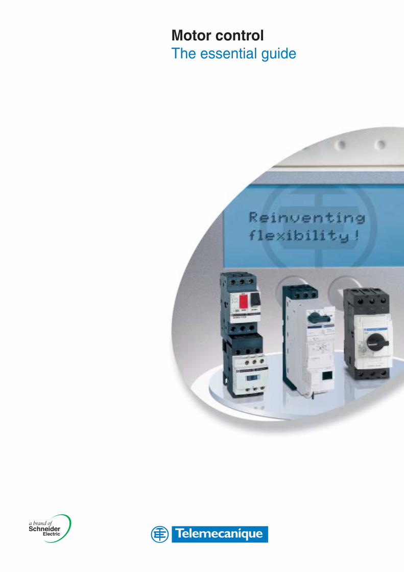
Motor controlThe essential guide
Mot
or c
ontr
ol
The essentialguideA simplifiedselection guideenabling you toquickly selectmotor starters.
For a new start!
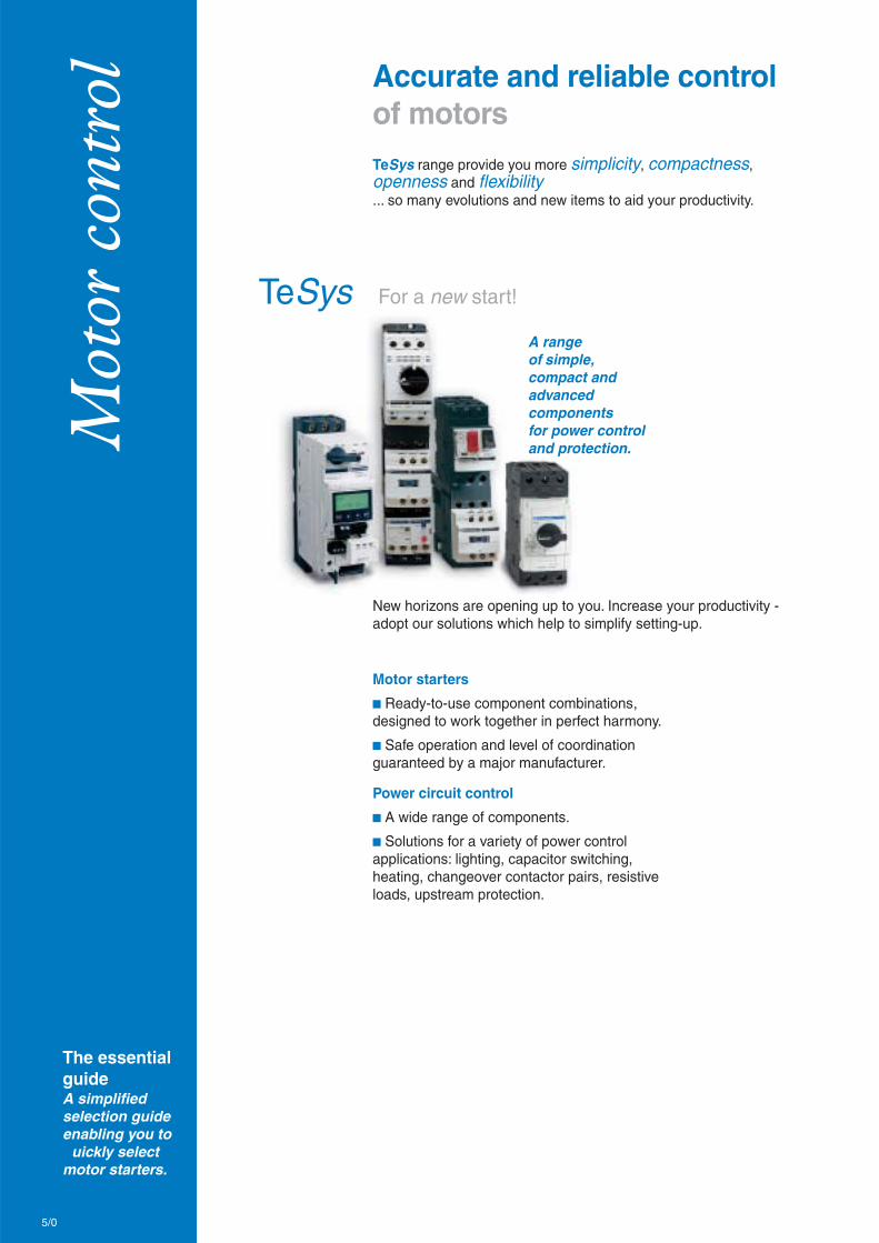
Accurate and reliable controlof motors
TeSys
TeSys range provide you more simplicity, compactness,openness and flexibility... so many evolutions and new items to aid your productivity.
New horizons are opening up to you. Increase your productivity -adopt our solutions which help to simplify setting-up.
A rangeof simple,compact andadvancedcomponentsfor power controland protection.
Motor starters
b Ready-to-use component combinations,designed to work together in perfect harmony.
b Safe operation and level of coordinationguaranteed by a major manufacturer.
Power circuit control
b A wide range of components.
b Solutions for a variety of power controlapplications: lighting, capacitor switching,heating, changeover contactor pairs, resistiveloads, upstream protection.
5/0
TeSys UControl increases in power
Simply Smart benefits
Introducing the 1st intelligent startercapable of integrating motor control,control and changeover functions in aunit 45 mm wide! Simple in its modularformat, it is also open to standard busesand can monitor your applications via theweb.
Applicationsbbbbb Industry: ideal solution when the motorstarter needs to be decentralized in themachine or the process
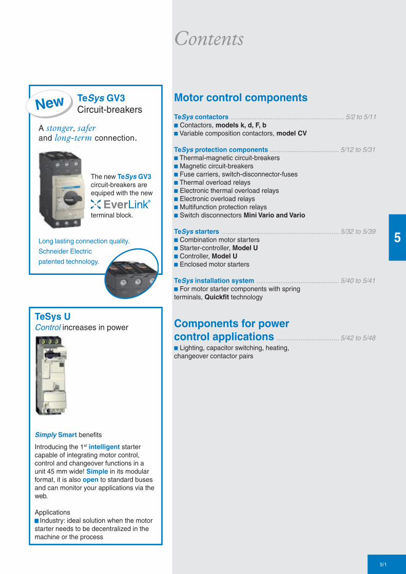
TeSys GV3Circuit-breakers
A stonger, saferand long-term connection.
The new TeSys GV3circuit-breakers areequiped with the new
terminal block.
Long lasting connection quality.
Schneider Electric
patented technology.
New
5/1
5
Contents
Motor control components
TeSys contactors .............................................................. 5/2 to 5/11b Contactors, models k, d, F, bb Variable composition contactors, model CV
TeSys protection components ...................................... 5/12 to 5/31b Thermal-magnetic circuit-breakersb Magnetic circuit-breakersb Fuse carriers, switch-disconnector-fusesb Thermal overload relaysb Electronic thermal overload relaysb Electronic overload relaysb Multifunction protection relaysb Switch disconnectors Mini Vario and Vario
TeSys starters ................................................................ 5/32 to 5/39b Combination motor startersb Starter-controller, Model Ub Controller, Model Ub Enclosed motor starters
TeSys installation system ............................................. 5/40 to 5/41b For motor starter components with springterminals, Quickfit technology
Components for powercontrol applications .................................. 5/42 to 5/48b Lighting, capacitor switching, heating,changeover contactor pairs

Other versions: please consult your Schneider Electric agency.5/2
5
Connections■ screw clamp terminals
Rated operational current Ie max AC-3 (Ue ≤ 440V) 6 A 9 A 12 A
Ie AC-1 (θ ≤ 40° C) - 20 A -
Rated operational power 220/240 V 1.5 kW 2.2 kW 3 kW
in category AC3 380/400 V…415/440 V 2.2 kW 4 kW 5.5 kW
660/690 V…500 V 3 kW 4 kW 4 kW
Contactor type (1)* c LC1-K06•• LC1-K09•• LC1-K12••
a LP1-K06•• or LP4-K06•• LP1-K09 or LP4-K09•• LP1-K12 or LP4-K12••
Reversing contactor type * c LC2-K06 LC2-K09 LC2-K12
with mechanical interlock a LP2-K06 or LP5-K06 LP2-K09 or LP5-K09 LP2-K12 or LP5-K12
■ spring terminals
Add the figure 3 before the voltage code. Example LC1-K0610•• becomes LC1-K06103••
■ Faston connectors, 1 x 6.35 or 2 x 2.8
Add the figure 7 before the voltage code. Example LC1-K0610•• becomes LC1-K06107••
■ solder pins for printed circuit boards
Add the figure 5 before the voltage code. Example LC1-K0610•• becomes LC1-K06105••
(1) Basic reference, to be completed by adding 01 for N/C auxiliary contact, or 10 for N/O auxiliary contact.
* Basic reference to be completed by adding the coil voltage
Standard control circuit voltagesc c c c c supply
Contactors LC1-K (0.8…1.15 Uc) (0.85…1.1UC)
Volts 12 20 24 36 42 48 110 115 120 127 200/208 220/230 230 230/240
50/60 Hz J7 Z7 B7 C7 D7 E7 F7 FE7 G7 FC7 L7 M7 P7 U7
Volts 256 277 380/400 400 400/415 440 480 500 575 600 660/690
50/60 Hz W7 UE7 Q7 V7 N7 R7 T7 S7 SC7 X7 Y7
Example of complete reference LC1-K0910P7
a a a a a supply
Contactors LP1-K (0.8…1.15 Uc)
Volts 12 20 24 36 48 60 72 100 110 125 155 174 200 220 230 240 250
Code JD ZD BD CD ED ND SD KD FD GD PD QD LD MD MPD MUD UD
Coil with integral suppression device available, add 3 to the code required. Example JD3
Low consumption
Contactors LP4-K (0.7…1.30 Uc), coil suppression as standard
Volts 12 20 24 48 72 110 120
Code JW3 ZW3 BW3 EW3 SW3 FW3 GW3
Example of complete reference LC1-K0910BD
TeSysk
Contactors0.06…5.5 kW
Other versions: please consult your Schneider Electric agency.5/3
5
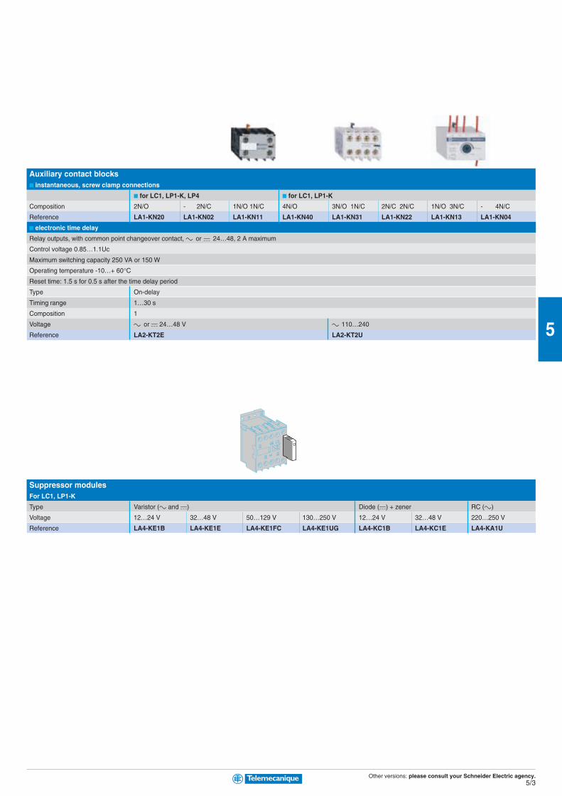
Auxiliary contact blocks■ instantaneous, screw clamp connections
■ for LC1, LP1-K, LP4 ■ for LC1, LP1-K
Composition 2N/O - 2N/C 1N/O 1N/C 4N/O 3N/O 1N/C 2N/C 2N/C 1N/O 3N/C - 4N/C
Reference LA1-KN20 LA1-KN02 LA1-KN11 LA1-KN40 LA1-KN31 LA1-KN22 LA1-KN13 LA1-KN04
■ electronic time delay
Relay outputs, with common point changeover contact, c or a 24…48, 2 A maximum
Control voltage 0.85…1.1Uc
Maximum switching capacity 250 VA or 150 W
Operating temperature -10…+ 60°CReset time: 1.5 s for 0.5 s after the time delay period
Type On-delay
Timing range 1…30 s
Composition 1
Voltage c or a 24…48 V c 110…240
Reference LA2-KT2E LA2-KT2U
Suppressor modulesFor LC1, LP1-K
Type Varistor (c and a) Diode (a) + zener RC (c)
Voltage 12…24 V 32…48 V 50…129 V 130…250 V 12…24 V 32…48 V 220…250 V
Reference LA4-KE1B LA4-KE1E LA4-KE1FC LA4-KE1UG LA4-KC1B LA4-KC1E LA4-KA1U
Other versions: please consult your Schneider Electric agency.5/4
5
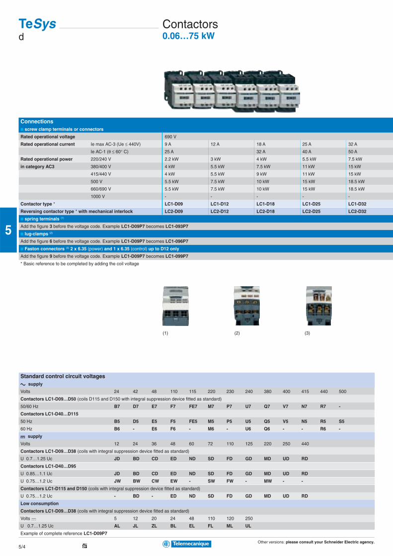
Connections■ screw clamp terminals or connectors
Rated operational voltage 690 V
Rated operational current Ie max AC-3 (Ue ≤ 440V) 9 A 12 A 18 A 25 A 32 A
Ie AC-1 (θ ≤ 60° C) 25 A 32 A 40 A 50 A
Rated operational power 220/240 V 2.2 kW 3 kW 4 kW 5.5 kW 7.5 kW
in category AC3 380/400 V 4 kW 5.5 kW 7.5 kW 11 kW 15 kW
415/440 V 4 kW 5.5 kW 9 kW 11 kW 15 kW
500 V 5.5 kW 7.5 kW 10 kW 15 kW 18.5 kW
660/690 V 5.5 kW 7.5 kW 10 kW 15 kW 18.5 kW
1000 V - - - - -
Contactor type * LC1-D09 LC1-D12 LC1-D18 LC1-D25 LC1-D32
Reversing contactor type * with mechanical interlock LC2-D09 LC2-D12 LC2-D18 LC2-D25 LC2-D32
■ spring terminals (1)
Add the figure 3 before the voltage code. Example LC1-D09P7 becomes LC1-093P7
■ lug-clamps (2)
Add the figure 6 before the voltage code. Example LC1-D09P7 becomes LC1-096P7
■ Faston connectors (3) 2 x 6.35 (power) and 1 x 6.35 (control) up to D12 only
Add the figure 9 before the voltage code. Example LC1-D09P7 becomes LC1-099P7
* Basic reference to be completed by adding the coil voltage
Standard control circuit voltagesc c c c c supply
Volts 24 42 48 110 115 220 230 240 380 400 415 440 500
Contactors LC1-D09…D50 (coils D115 and D150 with integral suppression device fitted as standard)
50/60 Hz B7 D7 E7 F7 FE7 M7 P7 U7 Q7 V7 N7 R7 -
Contactors LC1-D40…D115
50 Hz B5 D5 E5 F5 FE5 M5 P5 U5 Q5 V5 N5 R5 S5
60 Hz B6 - E6 F6 - M6 - U6 Q6 - - R6 -
a a a a a supply
Volts 12 24 36 48 60 72 110 125 220 250 440
Contactors LC1-D09…D38 (coils with integral suppression device fitted as standard)
U 0.7…1.25 Uc JD BD CD ED ND SD FD GD MD UD RD
Contactors LC1-D40…D95
U 0.85…1.1 Uc JD BD CD ED ND SD FD GD MD UD RD
U 0.75…1.2 Uc JW BW CW EW - SW FW - MW - -
Contactors LC1-D115 and D150 (coils with integral suppression device fitted as standard)
U 0.75…1.2 Uc - BD - ED ND SD FD GD MD UD RD
Low consumption
Contactors LC1-D09…D38 (coils with integral suppression device fitted as standard)
Volts a 5 12 20 24 48 110 120 250
U 0.7…1.25 Uc AL JL ZL BL EL FL ML UL
Example of complete reference LC1-D09P7
TeSysd
Contactors0.06…75 kW
(1) (3)(2)
Other versions: please consult your Schneider Electric agency.5/5
5
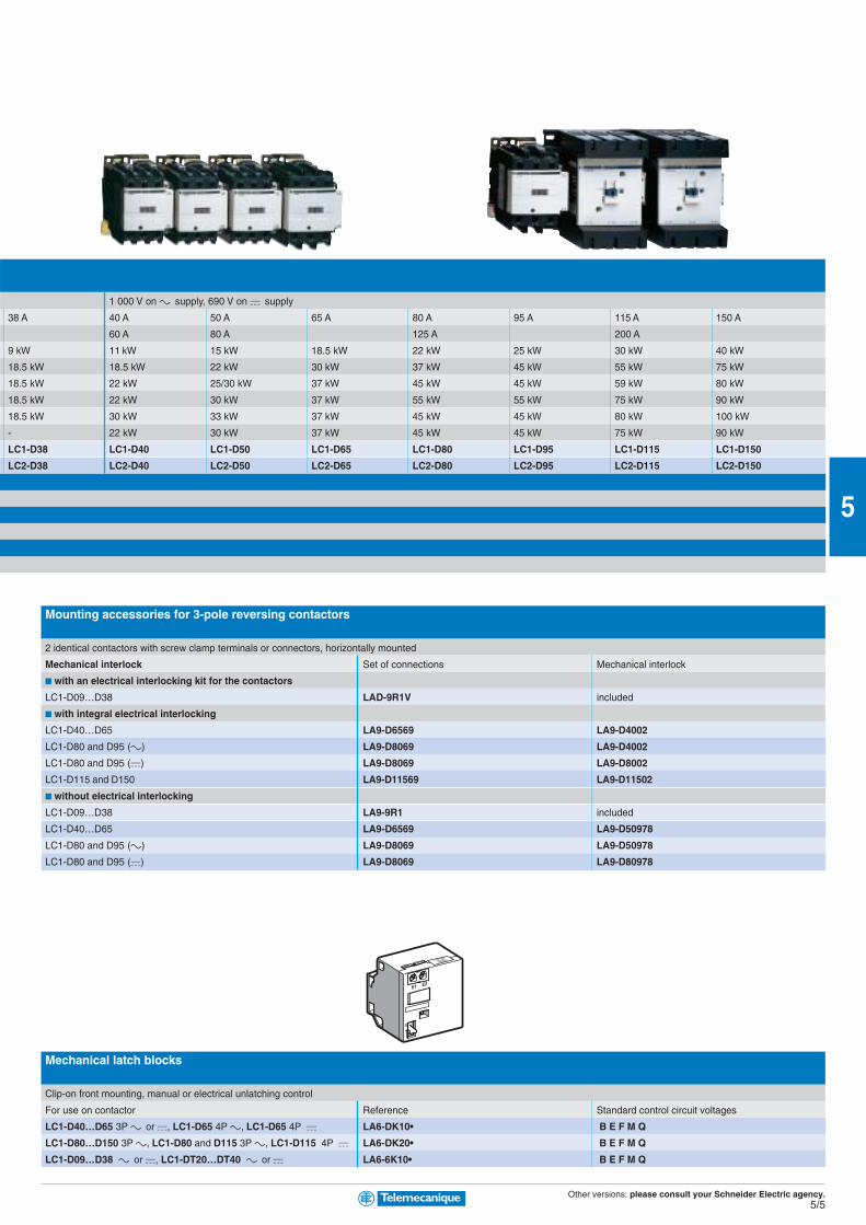
Mounting accessories for 3-pole reversing contactors
2 identical contactors with screw clamp terminals or connectors, horizontally mounted
Mechanical interlock Set of connections Mechanical interlock
■ with an electrical interlocking kit for the contactors
LC1-D09…D38 LAD-9R1V included
■ with integral electrical interlocking
LC1-D40…D65 LA9-D6569 LA9-D4002
LC1-D80 and D95 (c) LA9-D8069 LA9-D4002
LC1-D80 and D95 (a) LA9-D8069 LA9-D8002
LC1-D115 and D150 LA9-D11569 LA9-D11502
■ without electrical interlocking
LC1-D09…D38 LA9-9R1 included
LC1-D40…D65 LA9-D6569 LA9-D50978
LC1-D80 and D95 (c) LA9-D8069 LA9-D50978
LC1-D80 and D95 (a) LA9-D8069 LA9-D80978
Mechanical latch blocks
Clip-on front mounting, manual or electrical unlatching control
For use on contactor Reference Standard control circuit voltages
LC1-D40…D65 3P c or a, LC1-D65 4P c, LC1-D65 4P a LA6-DK10• B E F M Q
LC1-D80…D150 3P c, LC1-D80 and D115 3P c, LC1-D115 4P a LA6-DK20• B E F M Q
LC1-D09…D38 c or a, LC1-DT20…DT40 c or a LA6-6K10• B E F M Q
1 000 V on c supply, 690 V on a supply
38 A 40 A 50 A 65 A 80 A 95 A 115 A 150 A
60 A 80 A 125 A 200 A
9 kW 11 kW 15 kW 18.5 kW 22 kW 25 kW 30 kW 40 kW
18.5 kW 18.5 kW 22 kW 30 kW 37 kW 45 kW 55 kW 75 kW
18.5 kW 22 kW 25/30 kW 37 kW 45 kW 45 kW 59 kW 80 kW
18.5 kW 22 kW 30 kW 37 kW 55 kW 55 kW 75 kW 90 kW
18.5 kW 30 kW 33 kW 37 kW 45 kW 45 kW 80 kW 100 kW
- 22 kW 30 kW 37 kW 45 kW 45 kW 75 kW 90 kW
LC1-D38 LC1-D40 LC1-D50 LC1-D65 LC1-D80 LC1-D95 LC1-D115 LC1-D150
LC2-D38 LC2-D40 LC2-D50 LC2-D65 LC2-D80 LC2-D95 LC2-D115 LC2-D150
Other versions: please consult your Schneider Electric agency.5/6
5Maximum number of auxiliary contacts that can be fittedContactors
Instantaneous auxiliary contact blocks Time delay
Type Number of poles and size Side mounting Front mounting Front mounting
1 contact 2 contacts 4 contacts
c 3P LC1-D09…D38 1 on LH side and - 1 or 1 or 1
LC1-D40…D95 (50/60 Hz) 1 on each side or 2 and 1 or 1 or 1
LC1-D40…D95 (50 or 60 Hz) 1 on each side and 2 and 1 or 1 or 1
LC1-D115 and D150 1 on LH side - and 1 or 1 or 1
4P LC1-DT20…DT40 1 on LH side - 1 or 1 or 1
LC1-D65 and D80 1 on each side or 1 or 1 or 1 or 1
LC1-D115 1 on each side and 1 or 1 or 1 or 1
a 3P LC1-D09…D38 - - 1 or 1 or 1
LC1-D40…D95 - 1 or 1 or 1 or 1
LC1-D115 and D150 1 on LH side and - 1 or 1 or 1
4P LC1-DT20…DT40 - - 1 or 1 or 1
LP1-D65 and D80 - 2 and 1 or 1 or 1
LC1-D115 1 on each side - and 1 or 1 or 1
Low Consumption 3P LC1-D09…D38 - - 1 - -
4P LC1-DT20…DT40 - - 1
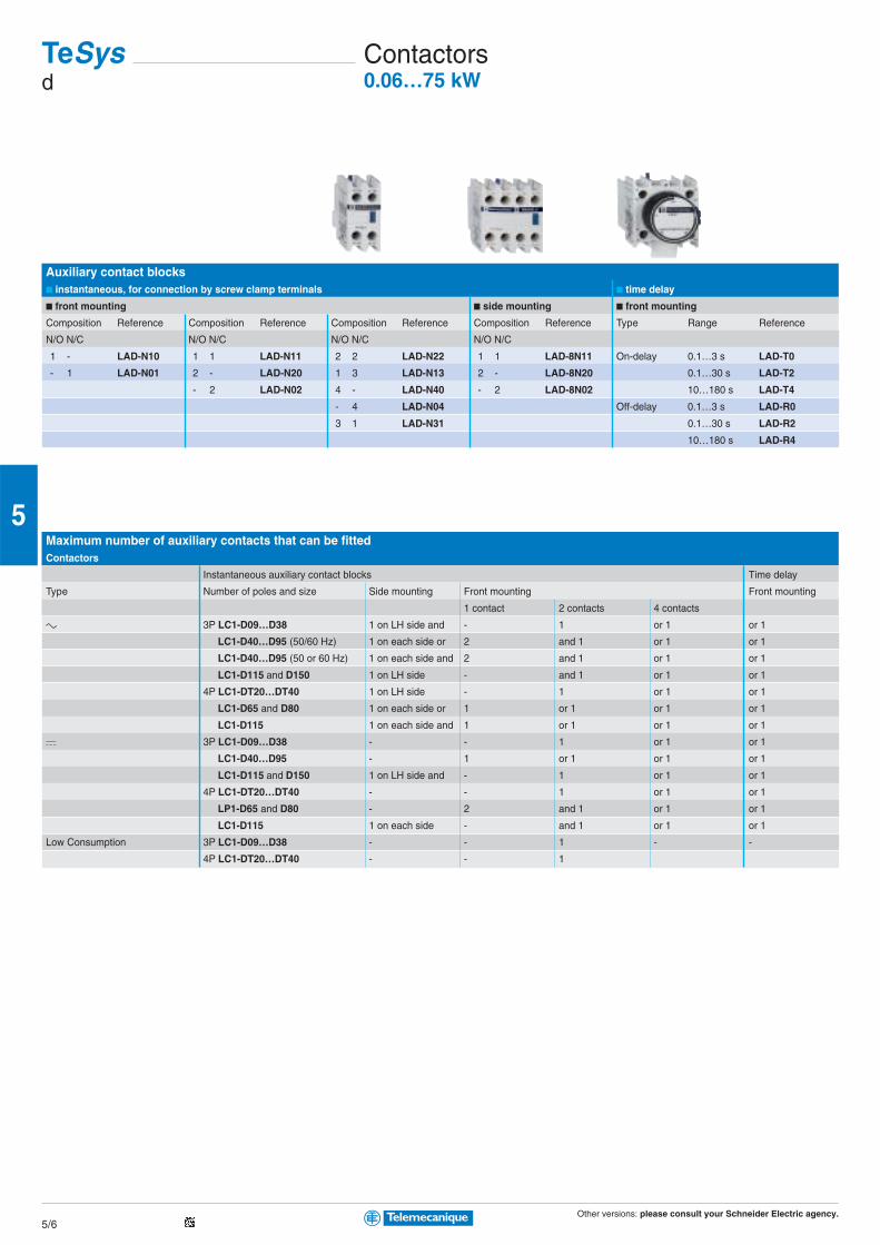
Auxiliary contact blocks■ instantaneous, for connection by screw clamp terminals ■ time delay
■ front mounting ■ side mounting ■ front mounting
Composition Reference Composition Reference Composition Reference Composition Reference Type Range Reference
N/O N/C N/O N/C N/O N/C N/O N/C
1 - LAD-N10 1 1 LAD-N11 2 2 LAD-N22 1 1 LAD-8N11 On-delay 0.1…3 s LAD-T0
- 1 LAD-N01 2 - LAD-N20 1 3 LAD-N13 2 - LAD-8N20 0.1…30 s LAD-T2
- 2 LAD-N02 4 - LAD-N40 - 2 LAD-8N02 10…180 s LAD-T4
- 4 LAD-N04 Off-delay 0.1…3 s LAD-R0
3 1 LAD-N31 0.1…30 s LAD-R2
10…180 s LAD-R4
TeSysd
Contactors0.06…75 kW
Other versions: please consult your Schneider Electric agency.5/7
5
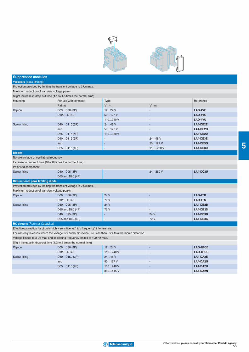
Suppressor modulesVaristors (peak limiting)
Protection provided by limiting the transient voltage to 2 Uc max.
Maximum reduction of transient voltage peaks.
Slight increase in drop-out time (1.1 to 1.5 times the normal time)
Mounting For use with contactor Type Reference
Rating V c V aClip-on D09…D38 (3P) 12…24 V - LAD-4VE
DT20…DT40 50…127 V - LAD-4VG
110…240 V - LAD-4VU
Screw fixing D40…D115 (3P) 24…48 V - LA4-DE2E
and 50…127 V - LA4-DE2G
D65…D115 (4P) 110…250 V - LA4-DE2U
D40…D115 (3P) - 24…48 V LA4-DE3E
and - 50…127 V LA4-DE3G
D65…D115 (4P) - 110…250 V LA4-DE3U
Diodes
No overvoltage or oscillating frequency.
Increase in drop-out time (6 to 10 times the normal time).
Polarised component.
Screw fixing D40…D95 (3P) - 24…250 V LA4-DC3U
D65 and D80 (4P)
Bidirectional peak limiting diode
Protection provided by limiting the transient voltage to 2 Uc max.
Maximum reduction of transient voltage peaks.
Clip-on D09…D38 (3P) 24 V - LAD-4TB
DT20…DT40 72 V - LAD-4TS
Screw fixing D40…D95 (3P) 24 V - LA4-DB2B
D65 and D80 (4P) 72 V - LA4-DB2S
D40…D95 (3P) - 24 V LA4-DB3B
D65 and D80 (4P) - 72 V LA4-DB3S
RC circuits (Resistor-Capacitor)
Effective protection for circuits highly sensitive to "high frequency" interference.
For use only in cases where the voltage is virtually sinusoidal, i.e. less than - 5% total harmonic distortion.
Voltage limited to 3 Uc max and oscillating frequency limited to 400 Hz max.
Slight increase in drop-out time (1.2 to 2 times the normal time)
Clip-on D09…D38 (3P) 12…24 V - LAD-4RCE
DT20…DT40 110…240 V - LAD-4RCU
Screw fixing D40…D150 (3P) 24…48 V - LA4-DA2E
and 50…127 V - LA4-DA2G
D65…D115 (4P) 110…240 V - LA4-DA2U
380…415 V - LA4-DA2N
Other versions: please consult your Schneider Electric agency.5/8
5
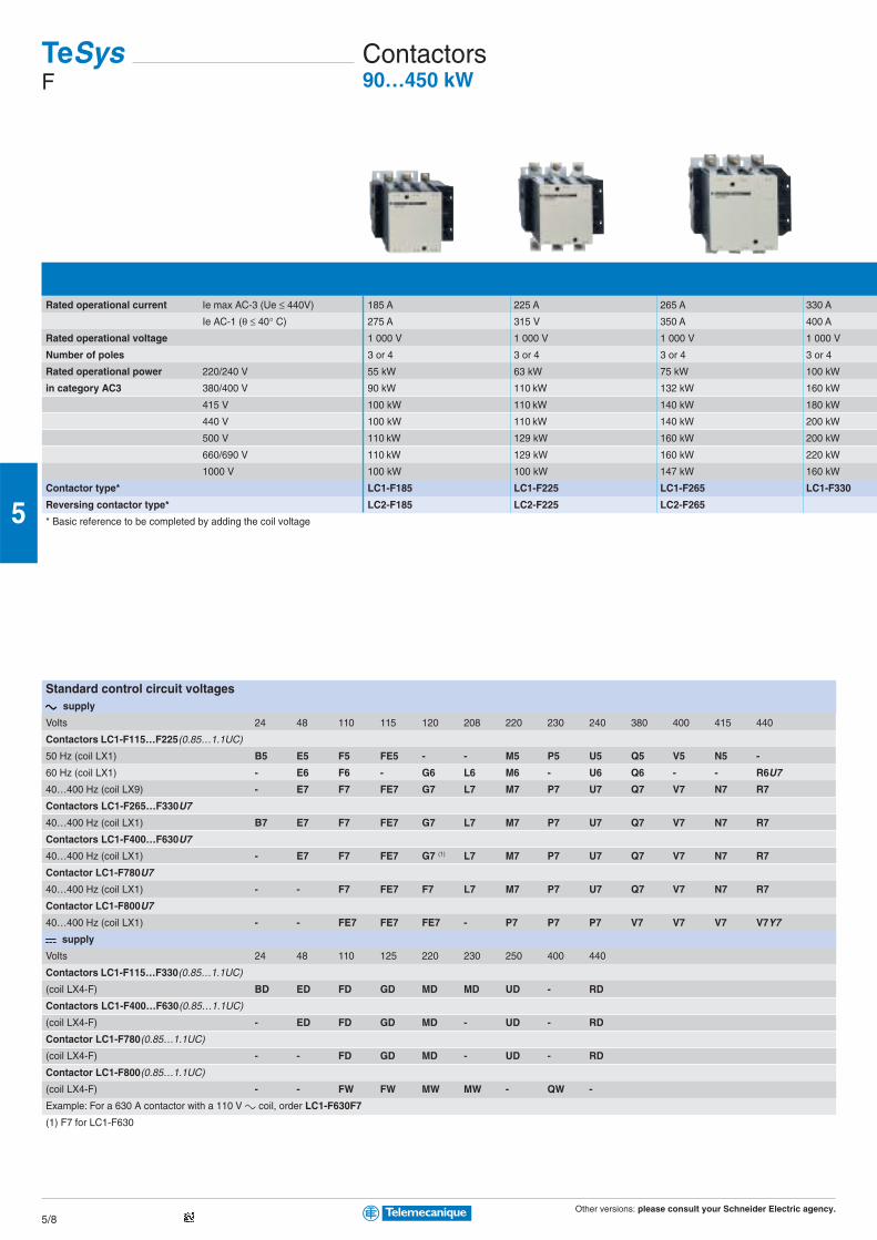
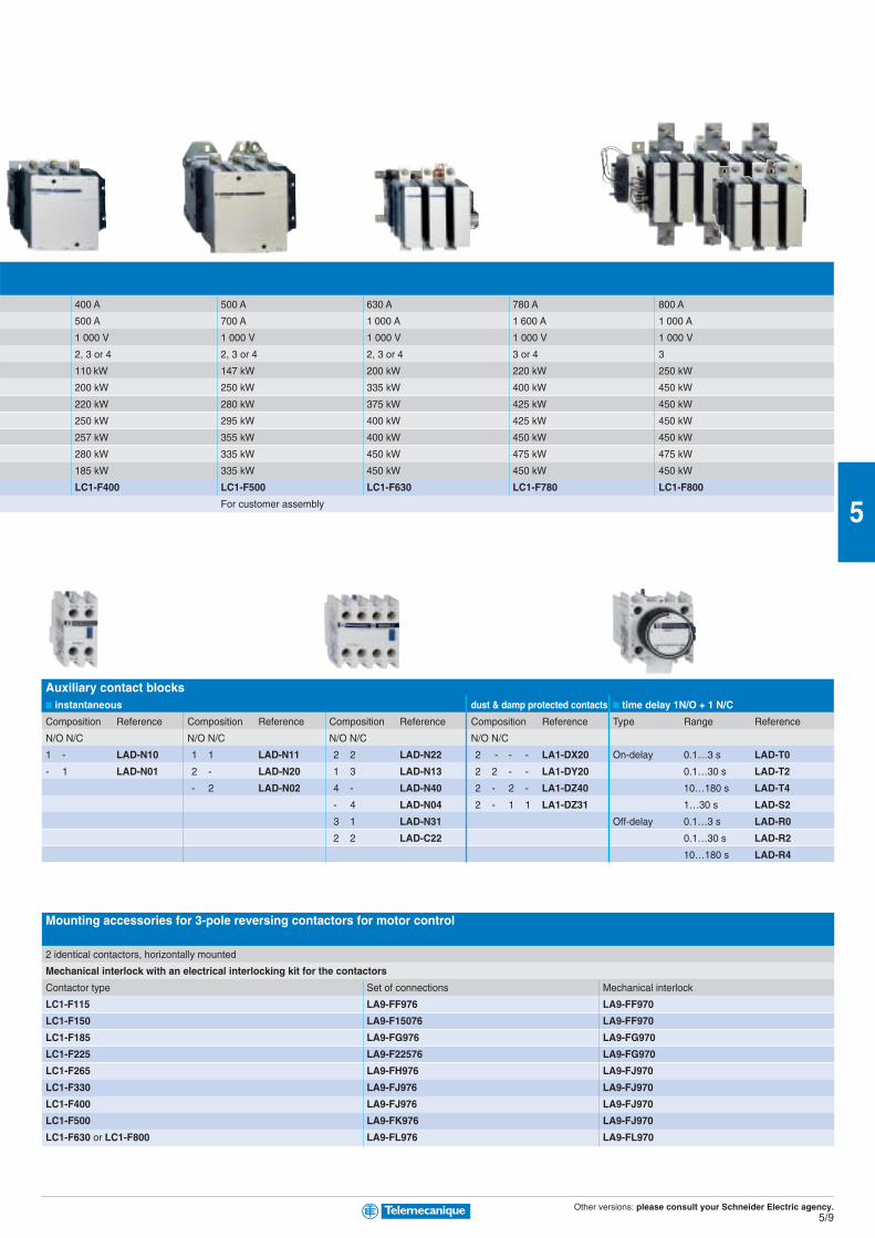
Rated operational current Ie max AC-3 (Ue ≤ 440V) 185 A 225 A 265 A 330 A
Ie AC-1 (θ ≤ 40° C) 275 A 315 V 350 A 400 A
Rated operational voltage 1 000 V 1 000 V 1 000 V 1 000 V
Number of poles 3 or 4 3 or 4 3 or 4 3 or 4
Rated operational power 220/240 V 55 kW 63 kW 75 kW 100 kW
in category AC3 380/400 V 90 kW 110 kW 132 kW 160 kW
415 V 100 kW 110 kW 140 kW 180 kW
440 V 100 kW 110 kW 140 kW 200 kW
500 V 110 kW 129 kW 160 kW 200 kW
660/690 V 110 kW 129 kW 160 kW 220 kW
1000 V 100 kW 100 kW 147 kW 160 kW
Contactor type* LC1-F185 LC1-F225 LC1-F265 LC1-F330
Reversing contactor type* LC2-F185 LC2-F225 LC2-F265
* Basic reference to be completed by adding the coil voltage
Standard control circuit voltagesc c c c c supply
Volts 24 48 110 115 120 208 220 230 240 380 400 415 440
Contactors LC1-F115…F225(0.85…1.1UC)
50 Hz (coil LX1) B5 E5 F5 FE5 - - M5 P5 U5 Q5 V5 N5 -
60 Hz (coil LX1) - E6 F6 - G6 L6 M6 - U6 Q6 - - R6U7
40…400 Hz (coil LX9) - E7 F7 FE7 G7 L7 M7 P7 U7 Q7 V7 N7 R7
Contactors LC1-F265…F330U7
40…400 Hz (coil LX1) B7 E7 F7 FE7 G7 L7 M7 P7 U7 Q7 V7 N7 R7
Contactors LC1-F400…F630U7
40…400 Hz (coil LX1) - E7 F7 FE7 G7 (1) L7 M7 P7 U7 Q7 V7 N7 R7
Contactor LC1-F780U7
40…400 Hz (coil LX1) - - F7 FE7 F7 L7 M7 P7 U7 Q7 V7 N7 R7
Contactor LC1-F800U7
40…400 Hz (coil LX1) - - FE7 FE7 FE7 - P7 P7 P7 V7 V7 V7 V7Y7
a a a a a supply
Volts 24 48 110 125 220 230 250 400 440
Contactors LC1-F115…F330(0.85…1.1UC)
(coil LX4-F) BD ED FD GD MD MD UD - RD
Contactors LC1-F400…F630(0.85…1.1UC)
(coil LX4-F) - ED FD GD MD - UD - RD
Contactor LC1-F780(0.85…1.1UC)
(coil LX4-F) - - FD GD MD - UD - RD
Contactor LC1-F800(0.85…1.1UC)
(coil LX4-F) - - FW FW MW MW - QW -
Example: For a 630 A contactor with a 110 V c coil, order LC1-F630F7
(1) F7 for LC1-F630
TeSysF
Contactors90…450 kW
Other versions: please consult your Schneider Electric agency.5/9
5
Auxiliary contact blocks■ instantaneous dust & damp protected contacts ■ time delay 1N/O + 1 N/C
Composition Reference Composition Reference Composition Reference Composition Reference Type Range Reference
N/O N/C N/O N/C N/O N/C N/O N/C
1 - LAD-N10 1 1 LAD-N11 2 2 LAD-N22 2 - - - LA1-DX20 On-delay 0.1…3 s LAD-T0
- 1 LAD-N01 2 - LAD-N20 1 3 LAD-N13 2 2 - - LA1-DY20 0.1…30 s LAD-T2
- 2 LAD-N02 4 - LAD-N40 2 - 2 - LA1-DZ40 10…180 s LAD-T4
- 4 LAD-N04 2 - 1 1 LA1-DZ31 1…30 s LAD-S2
3 1 LAD-N31 Off-delay 0.1…3 s LAD-R0
2 2 LAD-C22 0.1…30 s LAD-R2
10…180 s LAD-R4
Mounting accessories for 3-pole reversing contactors for motor control
2 identical contactors, horizontally mounted
Mechanical interlock with an electrical interlocking kit for the contactors
Contactor type Set of connections Mechanical interlock
LC1-F115 LA9-FF976 LA9-FF970
LC1-F150 LA9-F15076 LA9-FF970
LC1-F185 LA9-FG976 LA9-FG970
LC1-F225 LA9-F22576 LA9-FG970
LC1-F265 LA9-FH976 LA9-FJ970
LC1-F330 LA9-FJ976 LA9-FJ970
LC1-F400 LA9-FJ976 LA9-FJ970
LC1-F500 LA9-FK976 LA9-FJ970
LC1-F630 or LC1-F800 LA9-FL976 LA9-FL970
400 A 500 A 630 A 780 A 800 A
500 A 700 A 1 000 A 1 600 A 1 000 A
1 000 V 1 000 V 1 000 V 1 000 V 1 000 V
2, 3 or 4 2, 3 or 4 2, 3 or 4 3 or 4 3
110 kW 147 kW 200 kW 220 kW 250 kW
200 kW 250 kW 335 kW 400 kW 450 kW
220 kW 280 kW 375 kW 425 kW 450 kW
250 kW 295 kW 400 kW 425 kW 450 kW
257 kW 355 kW 400 kW 450 kW 450 kW
280 kW 335 kW 450 kW 475 kW 475 kW
185 kW 335 kW 450 kW 450 kW 450 kW
LC1-F400 LC1-F500 LC1-F630 LC1-F780 LC1-F800
For customer assembly
Other versions: please consult your Schneider Electric agency.5/10
5
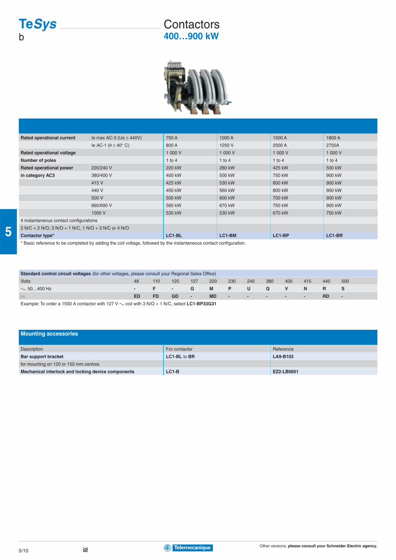
Standard control circuit voltages (for other voltages, please consult your Regional Sales Office)
Volts 48 110 125 127 220 230 240 380 400 415 440 500
c 50…400 Hz - F - G M P U Q V N R S
a ED FD GD - MD - - - - - RD -
Example: To order a 1500 A contactor with 127 V c coil with 3 N/O + 1 N/C, select LC1-BP33G31
Mounting accessories
Description For contactor Reference
Bar support bracket LC1-BL to BR LA9-B103
for mounting on 120 or 150 mm centres
Mechanical interlock and locking device components LC1-B EZ2-LB0601
Rated operational current Ie max AC-3 (Ue ≤ 440V) 750 A 1000 A 1500 A 1800 A
Ie AC-1 (θ ≤ 40° C) 800 A 1250 V 2000 A 2750A
Rated operational voltage 1 000 V 1 000 V 1 000 V 1 000 V
Number of poles 1 to 4 1 to 4 1 to 4 1 to 4
Rated operational power 220/240 V 220 kW 280 kW 425 kW 500 kW
in category AC3 380/400 V 400 kW 500 kW 750 kW 900 kW
415 V 425 kW 530 kW 800 kW 900 kW
440 V 450 kW 560 kW 800 kW 900 kW
500 V 500 kW 600 kW 700 kW 900 kW
660/690 V 560 kW 670 kW 750 kW 900 kW
1000 V 530 kW 530 kW 670 kW 750 kW
4 instantaneous contact configurations
2 N/C + 2 N/O, 3 N/O + 1 N/C, 1 N/O + 3 N/C or 4 N/O
Contactor type* LC1-BL LC1-BM LC1-BP LC1-BR
* Basic reference to be completed by adding the coil voltage, followed by the instantaneous contact configuration.
TeSysb
Contactors400…900 kW

Other versions: please consult your Schneider Electric agency.5/11
5
Reference to compiled by the customer
Contactor type, according to required use
c supply 690 V, a supply 220 V/pole CV1-B
c supply 1000 V, a supply 440 V/pole CV3-B
Contactor rating CV1: 80 A CV3: 80 A F
CV1: 200 A CV3: 170 A G
CV1: 300 A CV3: 250 A H
CV1: 470 A CV3: 320 A J
CV1: 630 A CV3: 500 A K
CV1: 1000 A L
Number of poles (PN1 main poles for CV1 and PA3 main poles for CV3)
Normally Open main poles 1 N/O 1
2 N/O 2
3 N/O 3
4 N/O 4
5 N/O 5
Normally Closed main poles 1 N/C 1
2 N/C 2
3 N/C 3
No main poles 0 Z 0 Z
Operational current 10 A E E
20 A N N
40 A P P
80 A F F
125 A R R
170 A W W
200 A G G
250 A S S
300 A H H
320 A T T
470 A J J
500 A V V
630 A K K
1000 A L L
Control circuit voltage 48 V E
110 V F
120 V K
208 V L
220 V M
230 V P
240 V U
380 V Q
400 V V
440 V R
Operating frequency 50 Hz 5
60 Hz 6
50/60 Hz 7
a D
a + economy resistor R
Instantaneous auxiliary contacts
Normally Open 1 N/O 1
2 N/O 2
3 N/O 3
4 N/O 4
Normally Closed 1 N/C 1
2 N/C 2
3 N/C 3
4 N/C 4
Without instantaneous contact 0 0
On-delay 1 C/O J
Off-delay 1 C/O N
Example 1/ for single-phase capacitor switching: 400 V - 80 A - 1 N/O pole - Control circuit 220 V / 50 Hz, 1 N/O and 1 1N/C auxiliary contacts: CV1-BF1F0ZM511.
2/ for heating circuits, d.c. supply 800 V - 150 A - 2 N/O poles - Control circuit 48 V a , 1 N/O + 1 N/O On-delay auxiliary contacts: CV3-BG2W0ZED10J
TeSysCV1-B, CV3-B
Contactors variable compositionCV1-B : 80…1000 A, CV3-B : 80…500 A
Other versions: please consult your Schneider Electric agency.5/12
5
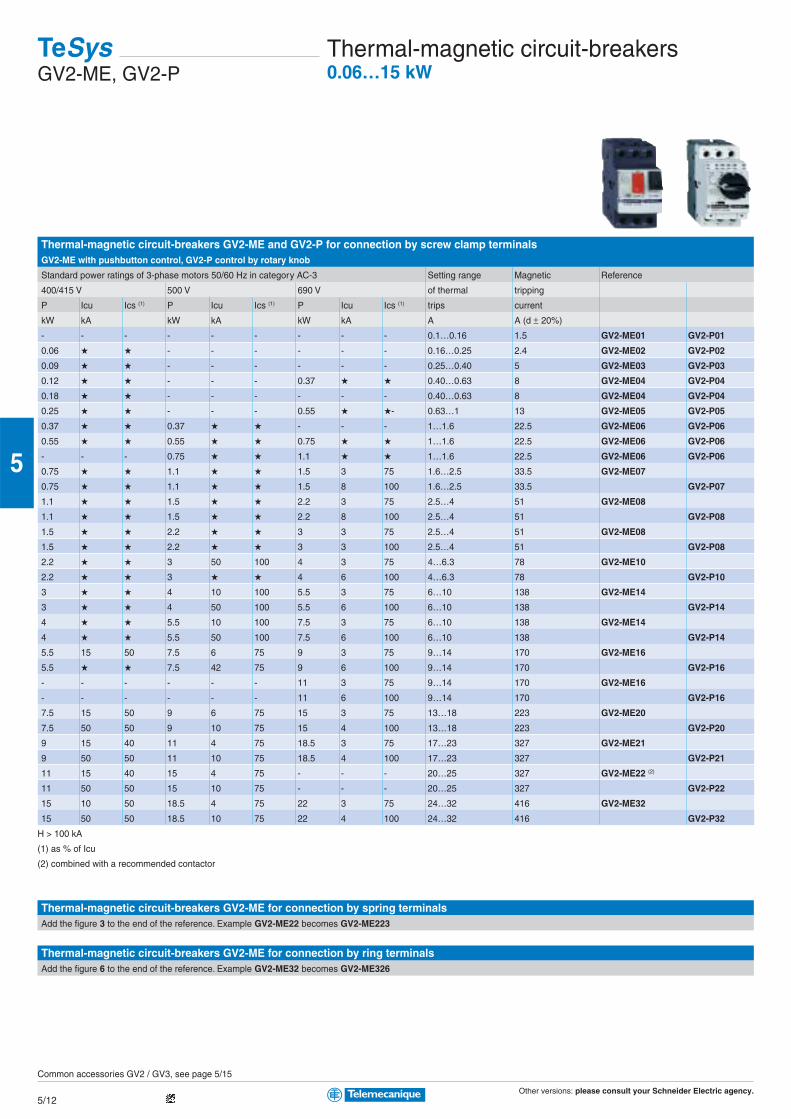
Thermal-magnetic circuit-breakers GV2-ME and GV2-P for connection by screw clamp terminalsGV2-ME with pushbutton control, GV2-P control by rotary knob
Standard power ratings of 3-phase motors 50/60 Hz in category AC-3 Setting range Magnetic Reference
400/415 V 500 V 690 V of thermal tripping
P Icu Ics (1) P Icu Ics (1) P Icu Ics (1) trips current
kW kA kW kA kW kA A A (d ± 20%)
- - - - - - - - - 0.1…0.16 1.5 GV2-ME01 GV2-P01
0.06 ★ ★ - - - - - - 0.16…0.25 2.4 GV2-ME02 GV2-P02
0.09 ★ ★ - - - - - - 0.25…0.40 5 GV2-ME03 GV2-P03
0.12 ★ ★ - - - 0.37 ★ ★ 0.40…0.63 8 GV2-ME04 GV2-P04
0.18 ★ ★ - - - - - - 0.40…0.63 8 GV2-ME04 GV2-P04
0.25 ★ ★ - - - 0.55 ★ ★- 0.63…1 13 GV2-ME05 GV2-P05
0.37 ★ ★ 0.37 ★ ★ - - - 1…1.6 22.5 GV2-ME06 GV2-P06
0.55 ★ ★ 0.55 ★ ★ 0.75 ★ ★ 1…1.6 22.5 GV2-ME06 GV2-P06
- - - 0.75 ★ ★ 1.1 ★ ★ 1…1.6 22.5 GV2-ME06 GV2-P06
0.75 ★ ★ 1.1 ★ ★ 1.5 3 75 1.6…2.5 33.5 GV2-ME07
0.75 ★ ★ 1.1 ★ ★ 1.5 8 100 1.6…2.5 33.5 GV2-P07
1.1 ★ ★ 1.5 ★ ★ 2.2 3 75 2.5…4 51 GV2-ME08
1.1 ★ ★ 1.5 ★ ★ 2.2 8 100 2.5…4 51 GV2-P08
1.5 ★ ★ 2.2 ★ ★ 3 3 75 2.5…4 51 GV2-ME08
1.5 ★ ★ 2.2 ★ ★ 3 3 100 2.5…4 51 GV2-P08
2.2 ★ ★ 3 50 100 4 3 75 4…6.3 78 GV2-ME10
2.2 ★ ★ 3 ★ ★ 4 6 100 4…6.3 78 GV2-P10
3 ★ ★ 4 10 100 5.5 3 75 6…10 138 GV2-ME14
3 ★ ★ 4 50 100 5.5 6 100 6…10 138 GV2-P14
4 ★ ★ 5.5 10 100 7.5 3 75 6…10 138 GV2-ME14
4 ★ ★ 5.5 50 100 7.5 6 100 6…10 138 GV2-P14
5.5 15 50 7.5 6 75 9 3 75 9…14 170 GV2-ME16
5.5 ★ ★ 7.5 42 75 9 6 100 9…14 170 GV2-P16
- - - - - - 11 3 75 9…14 170 GV2-ME16
- - - - - - 11 6 100 9…14 170 GV2-P16
7.5 15 50 9 6 75 15 3 75 13…18 223 GV2-ME20
7.5 50 50 9 10 75 15 4 100 13…18 223 GV2-P20
9 15 40 11 4 75 18.5 3 75 17…23 327 GV2-ME21
9 50 50 11 10 75 18.5 4 100 17…23 327 GV2-P21
11 15 40 15 4 75 - - - 20…25 327 GV2-ME22 (2)
11 50 50 15 10 75 - - - 20…25 327 GV2-P22
15 10 50 18.5 4 75 22 3 75 24…32 416 GV2-ME32
15 50 50 18.5 10 75 22 4 100 24…32 416 GV2-P32
H > 100 kA
(1) as % of Icu
(2) combined with a recommended contactor
Thermal-magnetic circuit-breakers GV2-ME for connection by spring terminalsAdd the figure 3 to the end of the reference. Example GV2-ME22 becomes GV2-ME223
Thermal-magnetic circuit-breakers GV2-ME for connection by ring terminalsAdd the figure 6 to the end of the reference. Example GV2-ME32 becomes GV2-ME326
Common accessories GV2 / GV3, see page 5/15
TeSysGV2-ME, GV2-P
Thermal-magnetic circuit-breakers0.06…15 kW
Other versions: please consult your Schneider Electric agency.5/13
5
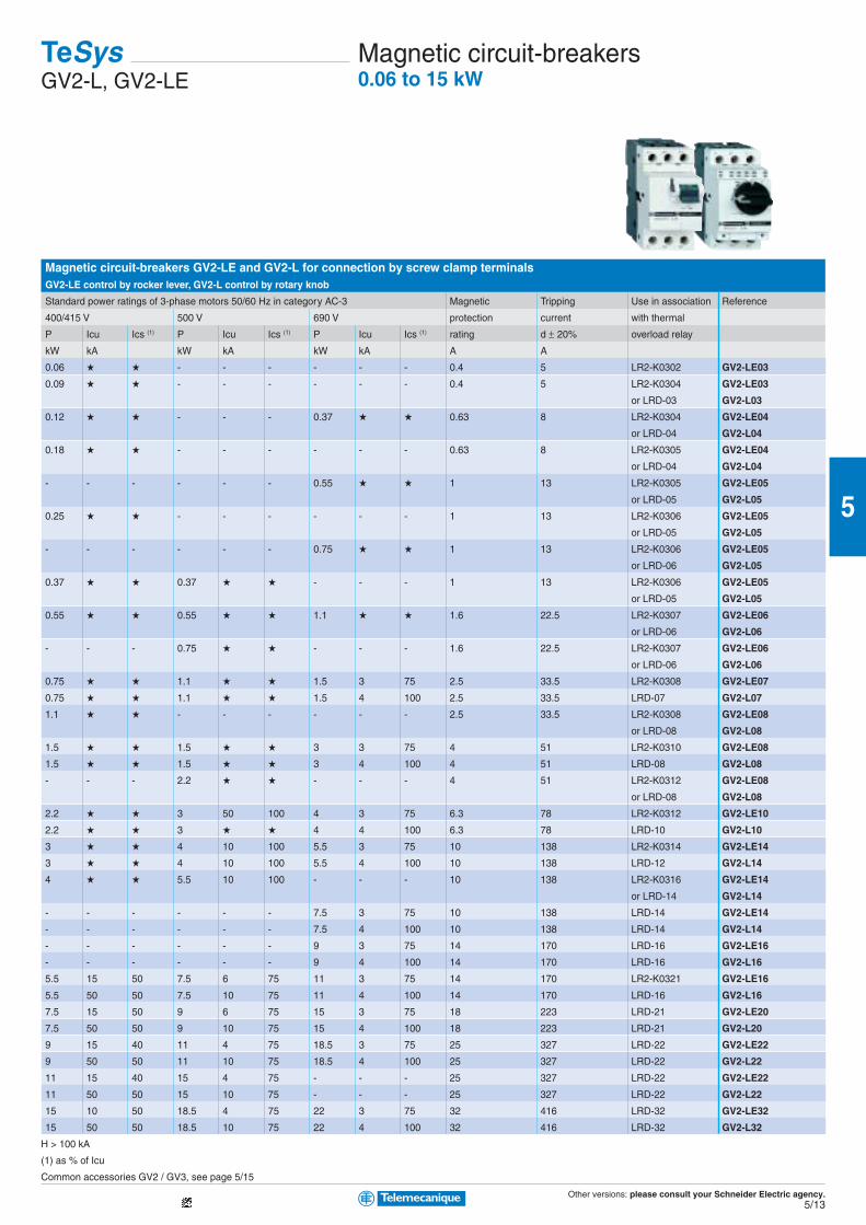
Magnetic circuit-breakers GV2-LE and GV2-L for connection by screw clamp terminalsGV2-LE control by rocker lever, GV2-L control by rotary knob
Standard power ratings of 3-phase motors 50/60 Hz in category AC-3 Magnetic Tripping Use in association Reference
400/415 V 500 V 690 V protection current with thermal
P Icu Ics (1) P Icu Ics (1) P Icu Ics (1) rating d ± 20% overload relay
kW kA kW kA kW kA A A
0.06 ★ ★ - - - - - - 0.4 5 LR2-K0302 GV2-LE03
0.09 ★ ★ - - - - - - 0.4 5 LR2-K0304 GV2-LE03
or LRD-03 GV2-L03
0.12 ★ ★ - - - 0.37 ★ ★ 0.63 8 LR2-K0304 GV2-LE04
or LRD-04 GV2-L04
0.18 ★ ★ - - - - - - 0.63 8 LR2-K0305 GV2-LE04
or LRD-04 GV2-L04
- - - - - - 0.55 ★ ★ 1 13 LR2-K0305 GV2-LE05
or LRD-05 GV2-L05
0.25 ★ ★ - - - - - - 1 13 LR2-K0306 GV2-LE05
or LRD-05 GV2-L05
- - - - - - 0.75 ★ ★ 1 13 LR2-K0306 GV2-LE05
or LRD-06 GV2-L05
0.37 ★ ★ 0.37 ★ ★ - - - 1 13 LR2-K0306 GV2-LE05
or LRD-05 GV2-L05
0.55 ★ ★ 0.55 ★ ★ 1.1 ★ ★ 1.6 22.5 LR2-K0307 GV2-LE06
or LRD-06 GV2-L06
- - - 0.75 ★ ★ - - - 1.6 22.5 LR2-K0307 GV2-LE06
or LRD-06 GV2-L06
0.75 ★ ★ 1.1 ★ ★ 1.5 3 75 2.5 33.5 LR2-K0308 GV2-LE07
0.75 ★ ★ 1.1 ★ ★ 1.5 4 100 2.5 33.5 LRD-07 GV2-L07
1.1 ★ ★ - - - - - - 2.5 33.5 LR2-K0308 GV2-LE08
or LRD-08 GV2-L08
1.5 ★ ★ 1.5 ★ ★ 3 3 75 4 51 LR2-K0310 GV2-LE08
1.5 ★ ★ 1.5 ★ ★ 3 4 100 4 51 LRD-08 GV2-L08
- - - 2.2 ★ ★ - - - 4 51 LR2-K0312 GV2-LE08
or LRD-08 GV2-L08
2.2 ★ ★ 3 50 100 4 3 75 6.3 78 LR2-K0312 GV2-LE10
2.2 ★ ★ 3 ★ ★ 4 4 100 6.3 78 LRD-10 GV2-L10
3 ★ ★ 4 10 100 5.5 3 75 10 138 LR2-K0314 GV2-LE14
3 ★ ★ 4 10 100 5.5 4 100 10 138 LRD-12 GV2-L14
4 ★ ★ 5.5 10 100 - - - 10 138 LR2-K0316 GV2-LE14
or LRD-14 GV2-L14
- - - - - - 7.5 3 75 10 138 LRD-14 GV2-LE14
- - - - - - 7.5 4 100 10 138 LRD-14 GV2-L14
- - - - - - 9 3 75 14 170 LRD-16 GV2-LE16
- - - - - - 9 4 100 14 170 LRD-16 GV2-L16
5.5 15 50 7.5 6 75 11 3 75 14 170 LR2-K0321 GV2-LE16
5.5 50 50 7.5 10 75 11 4 100 14 170 LRD-16 GV2-L16
7.5 15 50 9 6 75 15 3 75 18 223 LRD-21 GV2-LE20
7.5 50 50 9 10 75 15 4 100 18 223 LRD-21 GV2-L20
9 15 40 11 4 75 18.5 3 75 25 327 LRD-22 GV2-LE22
9 50 50 11 10 75 18.5 4 100 25 327 LRD-22 GV2-L22
11 15 40 15 4 75 - - - 25 327 LRD-22 GV2-LE22
11 50 50 15 10 75 - - - 25 327 LRD-22 GV2-L22
15 10 50 18.5 4 75 22 3 75 32 416 LRD-32 GV2-LE32
15 50 50 18.5 10 75 22 4 100 32 416 LRD-32 GV2-L32
H > 100 kA
(1) as % of Icu
Common accessories GV2 / GV3, see page 5/15
TeSysGV2-L, GV2-LE
Magnetic circuit-breakers0.06 to 15 kW
Other versions: please consult your Schneider Electric agency.5/14
5
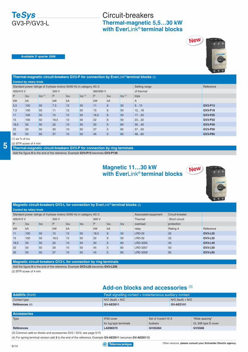
Thermal-magnetic circuit-breakers GV3-P for connection by EverLink® terminal blocks (2)
Control by rotary knob
Standard power ratings of 3-phase motors 50/60 Hz in category AC-3 Setting range Reference
400/415 V 500 V 660/690 V of thermal
P Icu Ics (1) P Icu Ics (1) P Icu Ics (1) trips
kW kA kW kA kW kA A
5,5 100 50 7,5 12 50 11 6 50 9…13 GV3-P13
7,5 100 50 11 12 50 15 6 50 12…18 GV3-P18
11 100 50 15 12 50 18,5 6 50 17…25 GV3-P25
15 100 50 18,5 12 50 22 6 50 23…32 GV3-P32
18,5 50 50 22 10 50 30 5 60 30…40 GV3-P40
22 50 50 30 10 50 37 5 60 37…50 GV3-P50
30 50 50 37 10 50 45 5 60 48…65 GV3-P65
(1) as % of Icu
(2) BTR screw of 4 mm
Thermal-magnetic circuit-breakers GV3-P for connection by ring terminalsAdd the figure 6 to the end of the reference. Example GV3-P13 becomes GV3-P136
Magnetic 11…30 kWwith EverLink® terminal blocks
Magnetic circuit-breakers GV3-L for connection by EverLink® terminal blocks (2)
Control by rotary knob
Standard power ratings of 3-phase motors 50/60 Hz in category AC-3 Associated equipment Circuit-breaker
400/415 V 500 V 690 V Thermal Short-circuit
P Icu Ics P Icu Ics P Icu Ics overload protection
kW kA kW kA kW kA relay Rating A Reference
11 100 50 15 12 50 18,5 6 50 LRD-22 25 GV3-L25
15 100 50 18,5 12 50 22 6 50 LRD-32 32 GV3-L32
18,5 50 50 22 10 50 30 5 60 LRD-3355 40 GV3-L40
22 50 50 30 10 50 45 5 60 LRD-3357 50 GV3-L50
30 50 50 37 10 50 45 5 60 LRD-3359 65 GV3-L65
Magnetic circuit-breakers GV3-L for connection by ring terminalsAdd the figure 6 to the end of the reference. Example GV3-L25 becomes GV3-L256
(2) BTR screw of 4 mm
Add-on blocks and accessories (3)
Additifs (front) Fault signalling contact + instantaneous auxiliary contactContact type N/O (fault) + N/C N/O (fault) + N/O
Références (4) GV-AED011 GV-AED101
AccessoriesType IP20 cover Set of 3-pole115 A “Wide spacing”
for lug type terminals busbars UL 508 type E cover
Références LAD96570 GV3G364 GV3G66
(3) Common add-on blocks and accessories GV2 / GV3, see page 5/15
(4) For spring terminal version add 3 to the end of the reference. Example GV-AED011 becomes GV-AED0113
TeSysGV3-P/GV3-L
Circuit-breakersThermal-magnetic 5,5…30 kWwith EverLink® terminal blocks
New
New
Available 3e quarter 2006
Other versions: please consult your Schneider Electric agency.5/15
5
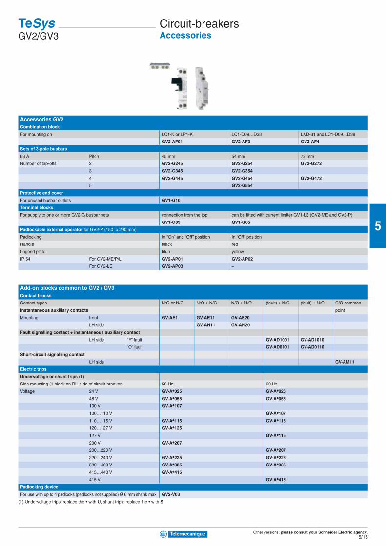
Accessories GV2Combination block
For mounting on LC1-K or LP1-K LC1-D09…D38 LAD-31 and LC1-D09…D38
GV2-AF01 GV2-AF3 GV2-AF4
Sets of 3-pole busbars
63 A Pitch 45 mm 54 mm 72 mm
Number of tap-offs 2 GV2-G245 GV2-G254 GV2-G272
3 GV2-G345 GV2-G354
4 GV2-G445 GV2-G454 GV2-G472
5 GV2-G554
Protective end cover
For unused busbar outlets GV1-G10
Terminal blocks
For supply to one or more GV2-G busbar sets connection from the top can be fitted with current limiter GV1-L3 (GV2-ME and GV2-P)
GV1-G09 GV1-G05
Padlockable external operator for GV2-P (150 to 290 mm)
Padlocking In “On” and “Off” position In “Off” position
Handle black red
Legend plate blue yellow
IP 54 For GV2-ME/P/L GV2-AP01 GV2-AP02
For GV2-LE GV2-AP03 –
Add-on blocks common to GV2 / GV3Contact blocks
Contact types N/O or N/C N/O + N/C N/O + N/O (fault) + N/C (fault) + N/O C/O common
Instantaneous auxiliary contacts point
Mounting front GV-AE1 GV-AE11 GV-AE20
LH side GV-AN11 GV-AN20
Fault signalling contact + instantaneous auxiliary contact
LH side “F” fault GV-AD1001 GV-AD1010
“O” fault GV-AD0101 GV-AD0110
Short-circuit signalling contact
LH side GV-AM11
Electric trips
Undervoltage or shunt trips (1)
Side mounting (1 block on RH side of circuit-breaker) 50 Hz 60 Hz
Voltage 24 V GV-A•025 GV-A•026
48 V GV-A•055 GV-A•056
100 V GV-A•107
100…110 V GV-A•107
110…115 V GV-A•115 GV-A•116
120…127 V GV-A•125
127 V GV-A•115
200 V GV-A•207
200…220 V GV-A•207
220…240 V GV-A•225 GV-A•226
380…400 V GV-A•385 GV-A•386
415…440 V GV-A•415
415 V GV-A•416
Padlocking device
For use with up to 4 padlocks (padlocks not supplied) Ø 6 mm shank max GV2-V03
(1) Undervoltage trips: replace the • with U, shunt trips: replace the • with S
TeSysGV2/GV3
Circuit-breakersAccessories
Other versions: please consult your Schneider Electric agency.5/16
5
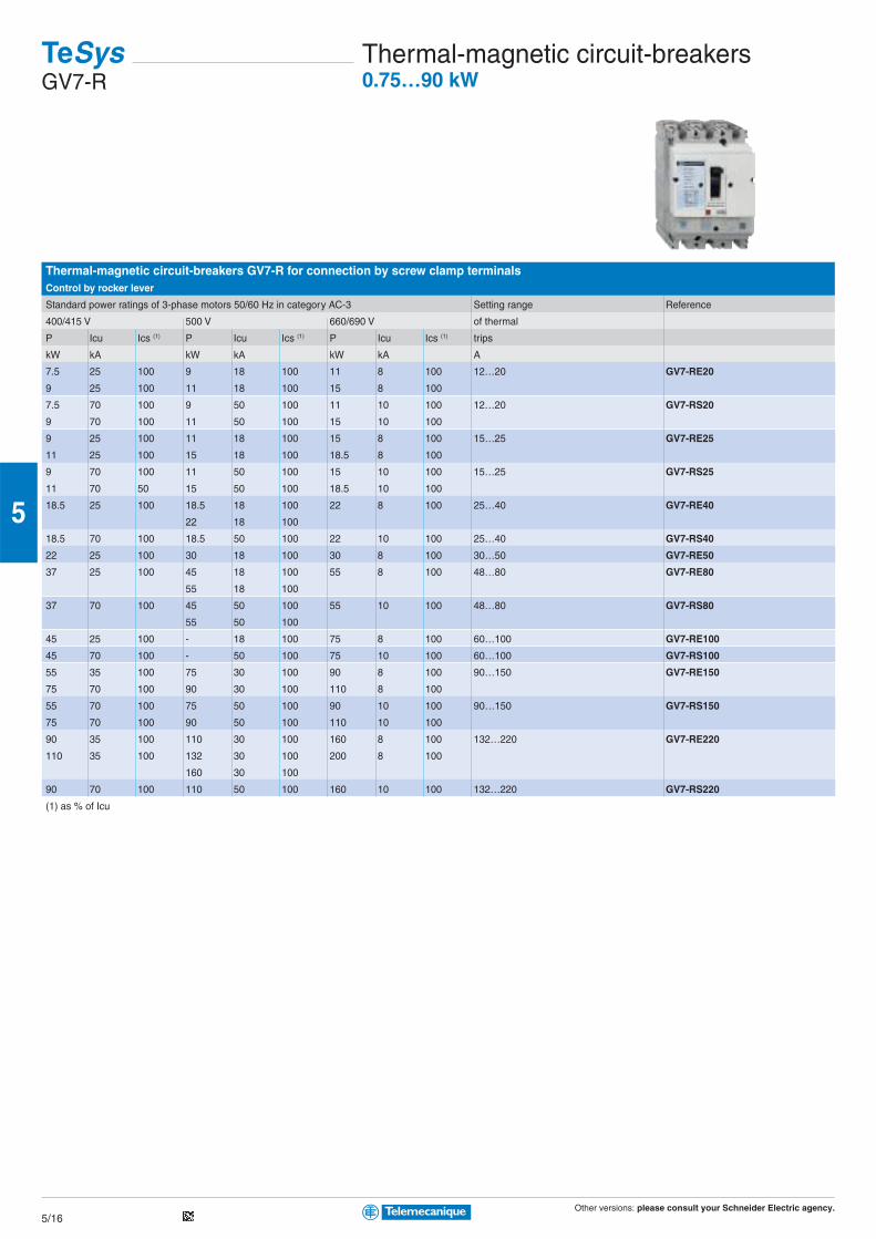
Thermal-magnetic circuit-breakers GV7-R for connection by screw clamp terminalsControl by rocker lever
Standard power ratings of 3-phase motors 50/60 Hz in category AC-3 Setting range Reference
400/415 V 500 V 660/690 V of thermal
P Icu Ics (1) P Icu Ics (1) P Icu Ics (1) trips
kW kA kW kA kW kA A
7.5 25 100 9 18 100 11 8 100 12…20 GV7-RE20
9 25 100 11 18 100 15 8 100
7.5 70 100 9 50 100 11 10 100 12…20 GV7-RS20
9 70 100 11 50 100 15 10 100
9 25 100 11 18 100 15 8 100 15…25 GV7-RE25
11 25 100 15 18 100 18.5 8 100
9 70 100 11 50 100 15 10 100 15…25 GV7-RS25
11 70 50 15 50 100 18.5 10 100
18.5 25 100 18.5 18 100 22 8 100 25…40 GV7-RE40
22 18 100
18.5 70 100 18.5 50 100 22 10 100 25…40 GV7-RS40
22 25 100 30 18 100 30 8 100 30…50 GV7-RE50
37 25 100 45 18 100 55 8 100 48…80 GV7-RE80
55 18 100
37 70 100 45 50 100 55 10 100 48…80 GV7-RS80
55 50 100
45 25 100 - 18 100 75 8 100 60…100 GV7-RE100
45 70 100 - 50 100 75 10 100 60…100 GV7-RS100
55 35 100 75 30 100 90 8 100 90…150 GV7-RE150
75 70 100 90 30 100 110 8 100
55 70 100 75 50 100 90 10 100 90…150 GV7-RS150
75 70 100 90 50 100 110 10 100
90 35 100 110 30 100 160 8 100 132…220 GV7-RE220
110 35 100 132 30 100 200 8 100
160 30 100
90 70 100 110 50 100 160 10 100 132…220 GV7-RS220
(1) as % of Icu
TeSysGV7-R
Thermal-magnetic circuit-breakers0.75…90 kW
Other versions: please consult your Schneider Electric agency.5/17
5
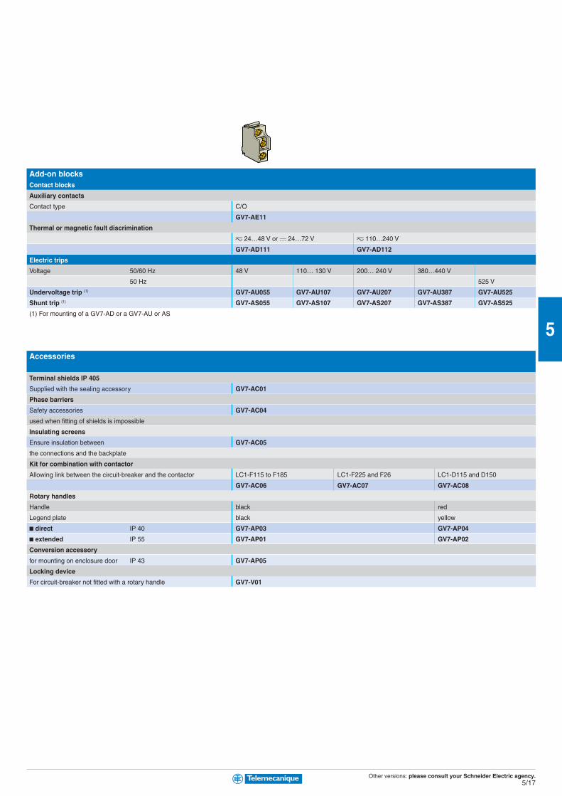
Add-on blocksContact blocks
Auxiliary contacts
Contact type C/O
GV7-AE11
Thermal or magnetic fault discrimination
z 24…48 V or a 24…72 V z 110…240 V
GV7-AD111 GV7-AD112
Electric trips
Voltage 50/60 Hz 48 V 110… 130 V 200… 240 V 380…440 V
50 Hz 525 V
Undervoltage trip (1) GV7-AU055 GV7-AU107 GV7-AU207 GV7-AU387 GV7-AU525
Shunt trip (1) GV7-AS055 GV7-AS107 GV7-AS207 GV7-AS387 GV7-AS525
(1) For mounting of a GV7-AD or a GV7-AU or AS
Accessories
Terminal shields IP 405
Supplied with the sealing accessory GV7-AC01
Phase barriers
Safety accessories GV7-AC04
used when fitting of shields is impossible
Insulating screens
Ensure insulation between GV7-AC05
the connections and the backplate
Kit for combination with contactor
Allowing link between the circuit-breaker and the contactor LC1-F115 to F185 LC1-F225 and F26 LC1-D115 and D150
GV7-AC06 GV7-AC07 GV7-AC08
Rotary handles
Handle black red
Legend plate black yellow
■ direct IP 40 GV7-AP03 GV7-AP04
■ extended IP 55 GV7-AP01 GV7-AP02
Conversion accessory
for mounting on enclosure door IP 43 GV7-AP05
Locking device
For circuit-breaker not fitted with a rotary handle GV7-V01
Other versions: please consult your Schneider Electric agency.5/18
5
Add-on blocks for GV3-MEContact blocks
Instantaneous auxiliary contacts (1 per breaker)
Normal early break type contacts N/C + N/O N/O + N/O N/C + N/O + N/O N/O + N/O + N/O N/O + N/O (1) N/C + N/O (1)
GV3-A01 GV3-A02 GV3-A03 GV3-A05 GV3-A06 GV3-A07
Fault signalling contact
Normal early break type contacts N/C N/O
GV3-A08 GV3-A09
Electric trips
Voltage 50 Hz 110, 120, 127 V 220, 240 V 380, 415 V
60 Hz 120, 127 V 277 V 440, 480 V
Undervoltage trip GV3-B11 GV3-B22 GV3-B38
Shunt trip GV3-D11 GV3-D22 GV3-D38
Padlocking device
Start button (for bare device) GV1-V02
(1) + 2 volt free terminals
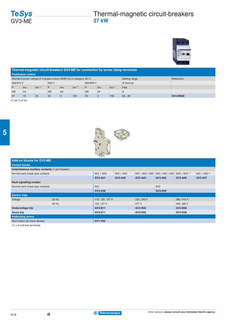
Thermal-magnetic circuit-breakers GV3-ME for connection by screw clamp terminalsPushbutton control
Standard power ratings of 3-phase motors 50/60 Hz in category AC-3 Setting range Reference
400/415 V 500 V 660/690 V of thermal
P Icu Ics (1) P Icu Ics (1) P Icu Ics (1) trips
kW kA kW kA kW kA A
37 15 50 45 4 100 55 2 100 56…80 GV3-ME80
(1) as % of Icu
TeSysGV3-ME
Thermal-magnetic circuit-breakers37 kW
Other versions: please consult your Schneider Electric agency.5/19
5
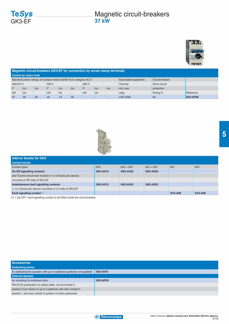
Magnetic circuit-breakers GK3-EF for connection by screw clamp terminalsControl by rotary knob
Standard power ratings of 3-phase motors 50/60 Hz in category AC-3 Associated equipment Circuit-breaker
400/415 V 500 V 690 V Thermal Short-circuit
P Icu Ics P Icu Ics P Icu Ics min. size protection
kW kA kW kA kW kA relay Rating A Reference
37 35 25 45 15 30 - - - LRD-3363 80 GK3-EF80
Add-on blocks for GK3Contact blocks
Contact types N/O N/O + N/O N/C + N/O N/C N/O
On-Off signalling contacts GK2-AX10 GK2-AX20 GK2-AX50
and “Control circuit test” function (1 or 2 blocks per device)
mounted on RH side of GK3-EF
Instantaneous fault signalling contacts GK2-AX12 GK2-AX22 GK2-AX52
(1 or 2 blocks per device) mounted on LH side of GK3-EF
Fault signalling contact (1) GV3-A08 GV3-A09
(1) 1 trip OR 1 fault signalling contact to be fitted inside the circuit-breaker.
AccessoriesPadlocking device
for padlocking the operator, with up to 3 padlocks (padlocks not supplied) GK3-AV01
External operator
for mounting on enclosure door. GK3-AP03
Red Ø 40 pushbutton on yellow plate, can be locked in
position O by means of up to 3 padlocks with door locked in
position I, and door locked in position O when padlocked
TeSysGK3-EF
Magnetic circuit-breakers37 kW
Other versions: please consult your Schneider Electric agency.5/20
5
TeSys Notes
Other versions: please consult your Schneider Electric agency.5/21
5
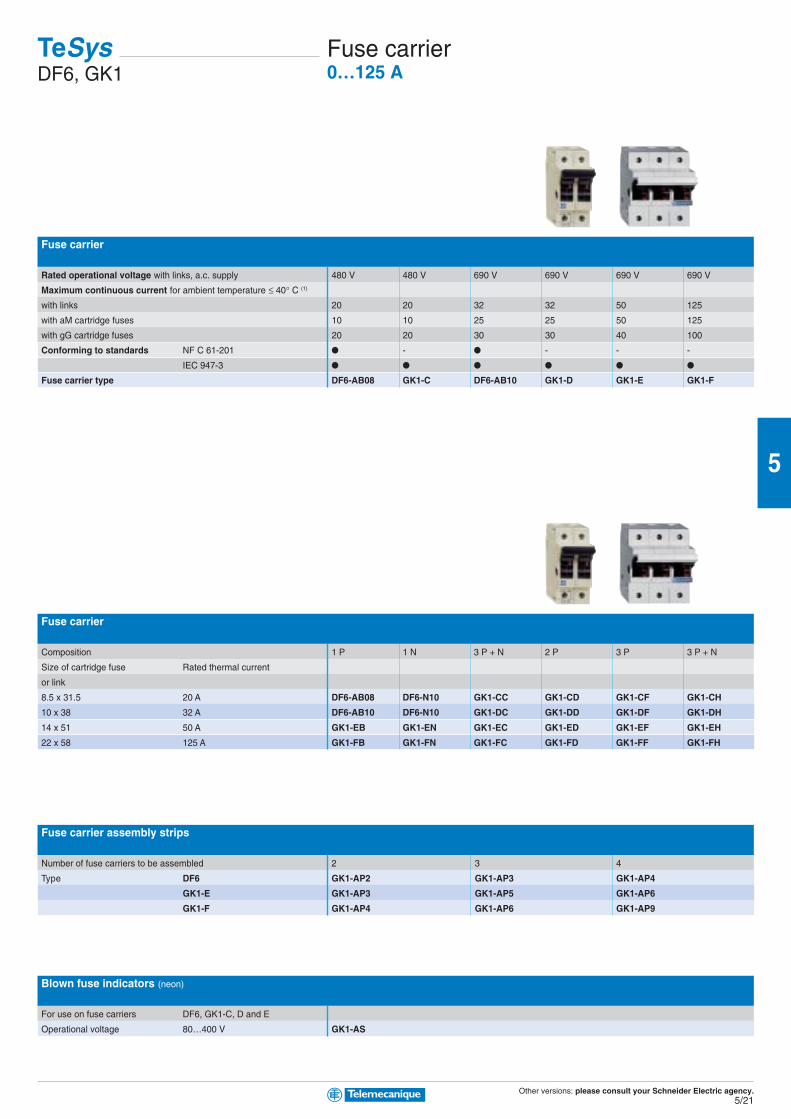
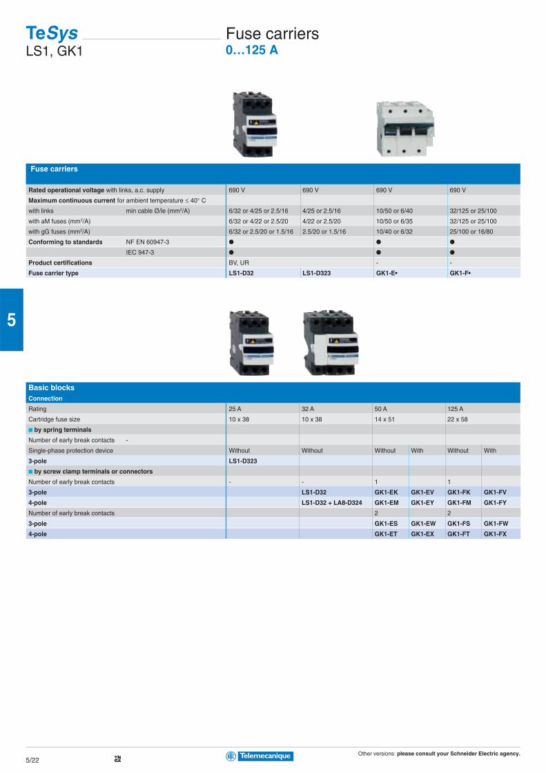
Fuse carrier
Rated operational voltage with links, a.c. supply 480 V 480 V 690 V 690 V 690 V 690 V
Maximum continuous current for ambient temperature ≤ 40° C (1)
with links 20 20 32 32 50 125
with aM cartridge fuses 10 10 25 25 50 125
with gG cartridge fuses 20 20 30 30 40 100
Conforming to standards NF C 61-201 ● - ● - - -
IEC 947-3 ● ● ● ● ● ●
Fuse carrier type DF6-AB08 GK1-C DF6-AB10 GK1-D GK1-E GK1-F
Fuse carrier
Composition 1 P 1 N 3 P + N 2 P 3 P 3 P + N
Size of cartridge fuse Rated thermal current
or link
8.5 x 31.5 20 A DF6-AB08 DF6-N10 GK1-CC GK1-CD GK1-CF GK1-CH
10 x 38 32 A DF6-AB10 DF6-N10 GK1-DC GK1-DD GK1-DF GK1-DH
14 x 51 50 A GK1-EB GK1-EN GK1-EC GK1-ED GK1-EF GK1-EH
22 x 58 125 A GK1-FB GK1-FN GK1-FC GK1-FD GK1-FF GK1-FH
Fuse carrier assembly strips
Number of fuse carriers to be assembled 2 3 4
Type DF6 GK1-AP2 GK1-AP3 GK1-AP4
GK1-E GK1-AP3 GK1-AP5 GK1-AP6
GK1-F GK1-AP4 GK1-AP6 GK1-AP9
Blown fuse indicators (neon)
For use on fuse carriers DF6, GK1-C, D and E
Operational voltage 80…400 V GK1-AS
TeSysDF6, GK1
Fuse carrier0…125 A
Other versions: please consult your Schneider Electric agency.5/22
5
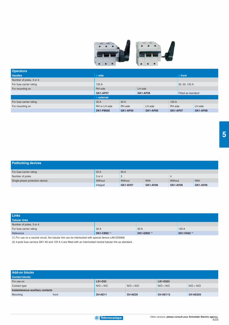
-Fuse carriers
Rated operational voltage with links, a.c. supply 690 V 690 V 690 V 690 V
Maximum continuous current for ambient temperature ≤ 40° Cwith links min cable Ø/le (mm2/A) 6/32 or 4/25 or 2.5/16 4/25 or 2.5/16 10/50 or 6/40 32/125 or 25/100
with aM fuses (mm2/A) 6/32 or 4/22 or 2.5/20 4/22 or 2.5/20 10/50 or 6/35 32/125 or 25/100
with gG fuses (mm2/A) 6/32 or 2.5/20 or 1.5/16 2.5/20 or 1.5/16 10/40 or 6/32 25/100 or 16/80
Conforming to standards NF EN 60947-3 ● ● ●
IEC 947-3 ● ● ●
Product certifications BV, UR - -
Fuse carrier type LS1-D32 LS1-D323 GK1-E• GK1-F•
Basic blocksConnection
Rating 25 A 32 A 50 A 125 A
Cartridge fuse size 10 x 38 10 x 38 14 x 51 22 x 58
■ by spring terminals
Number of early break contacts -
Single-phase protection device Without Without Without With Without With
3-pole LS1-D323
■ by screw clamp terminals or connectors
Number of early break contacts - - 1 1
3-pole LS1-D32 GK1-EK GK1-EV GK1-FK GK1-FV
4-pole LS1-D32 + LA8-D324 GK1-EM GK1-EY GK1-FM GK1-FY
Number of early break contacts 2 2
3-pole GK1-ES GK1-EW GK1-FS GK1-FW
4-pole GK1-ET GK1-EX GK1-FT GK1-FX
TeSysLS1, GK1
Fuse carriers0…125 A
Other versions: please consult your Schneider Electric agency.5/23
5
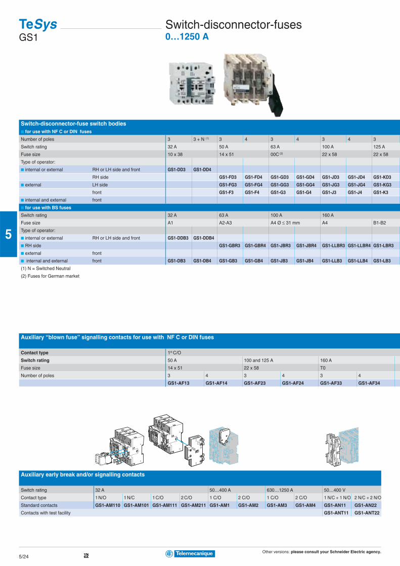
OperatorsHandles ■ side ■ front
Number of poles, 3 or 4
For fuse carrier rating 125 A 32, 50, 125 A
For mounting on RH side LH side
GK1-AP07 GK1-AP08 Fitted as standard
■ external
For fuse carrier rating 32 A 50 A 125 A
For mounting on RH or LH side RH side LH side RH side LH side
DK1-FB005 GK1-AP05 GK1-AP06 GK1-AP07 GK1-AP08
Padlocking devices
For fuse carrier rating 32 A 50 A
Number of poles 3 or 4 3 4
Single-phase protection device Without Without With Without With
Integral GK1-AV07 GK1-AV08 GK1-AV08 GK1-AV09
LinksTubular links
Number of poles, 3 or 4
For fuse carrier rating 32 A 50 A 125 A
Reference DK1-CB92 (1) DK1-EB92 (2) DK1-FA92 (2)
(1) For use on a neutral circuit, the tubular link can be interlocked with special device LA8-D25906.
(2) 4-pole fuse carriers GK1-50 and 125 A 4 are fitted with an interlocked neutral tubular link as standard.
Add-on blocksContact blocks
For use on LS1-D32 LS1-D323
Contact type N/O + N/C N/O + N/O N/O + N/C N/O + N/O
Instantaneous auxiliary contacts
Mounting front GV-AE11 GV-AE20 GV-AE113 GV-AE203
Other versions: please consult your Schneider Electric agency.5/24
5
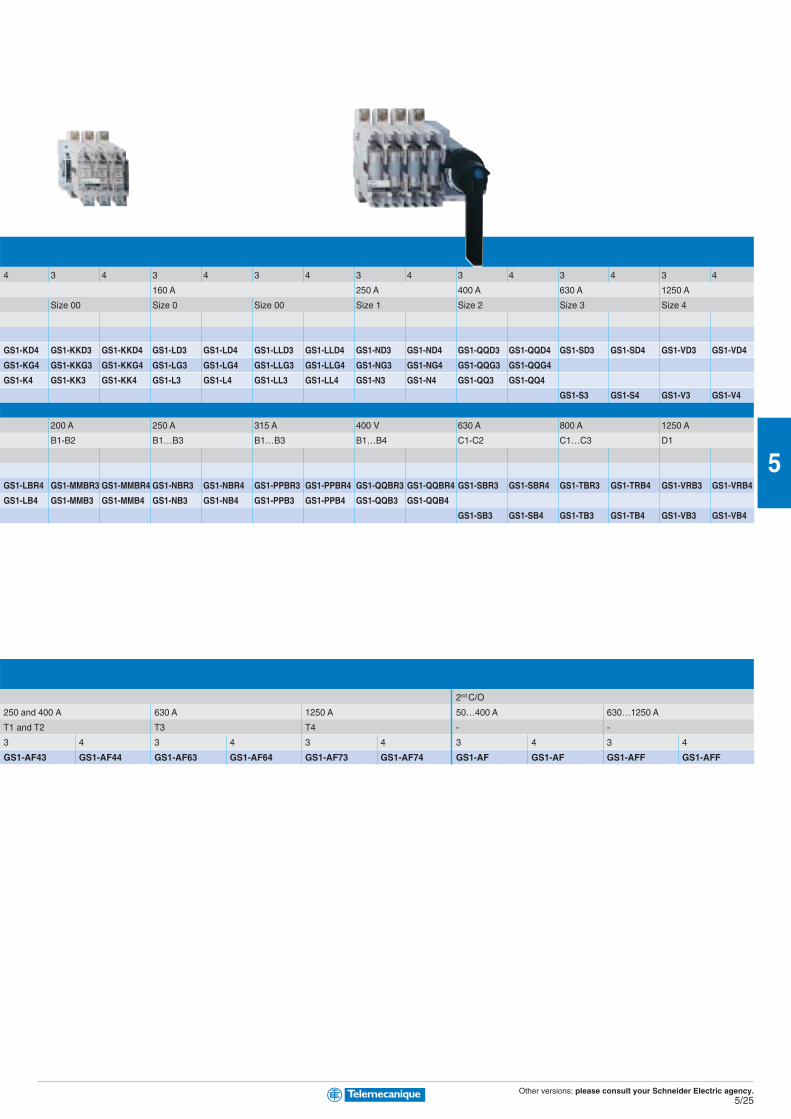
Switch-disconnector-fuse switch bodies■ for use with NF C or DIN fuses
Number of poles 3 3 + N (1) 3 4 3 4 3 4 3
Switch rating 32 A 50 A 63 A 100 A 125 A
Fuse size 10 x 38 14 x 51 00C (2) 22 x 58 22 x 58
Type of operator:
■ internal or external RH or LH side and front GS1-DD3 GS1-DD4
RH side GS1-FD3 GS1-FD4 GS1-GD3 GS1-GD4 GS1-JD3 GS1-JD4 GS1-KD3
■ external LH side GS1-FG3 GS1-FG4 GS1-GG3 GS1-GG4 GS1-JG3 GS1-JG4 GS1-KG3
front GS1-F3 GS1-F4 GS1-G3 GS1-G4 GS1-J3 GS1-J4 GS1-K3
■ internal and external front
■ for use with BS fuses
Switch rating 32 A 63 A 100 A 160 A
Fuse size A1 A2-A3 A4 Ø ≤ 31 mm A4 B1-B2
Type of operator:
■ internal or external RH or LH side and front GS1-DDB3 GS1-DDB4
■ RH side GS1-GBR3 GS1-GBR4 GS1-JBR3 GS1-JBR4 GS1-LLBR3 GS1-LLBR4 GS1-LBR3
■ external front
■ internal and external front GS1-DB3 GS1-DB4 GS1-GB3 GS1-GB4 GS1-JB3 GS1-JB4 GS1-LLB3 GS1-LLB4 GS1-LB3
(1) N = Switched Neutral
(2) Fuses for German market
Auxiliary “blown fuse” signalling contacts for use with NF C or DIN fuses
Contact type 1st C/O
Switch rating 50 A 100 and 125 A 160 A
Fuse size 14 x 51 22 x 58 T0
Number of poles 3 4 3 4 3 4
GS1-AF13 GS1-AF14 GS1-AF23 GS1-AF24 GS1-AF33 GS1-AF34
Auxiliary early break and/or signalling contacts
Switch rating 32 A 50…400 A 630…1250 A 50…400 V
Contact type 1 N/O 1 N/C 1 C/O 2 C/O 1 C/O 2 C/O 1 C/O 2 C/O 1 N/C + 1 N/O 2 N/C + 2 N/O
Standard contacts GS1-AM110 GS1-AM101 GS1-AM111 GS1-AM211 GS1-AM1 GS1-AM2 GS1-AM3 GS1-AM4 GS1-AN11 GS1-AN22
Contacts with test facility GS1-ANT11 GS1-ANT22
TeSysGS1
Switch-disconnector-fuses0…1250 A
Other versions: please consult your Schneider Electric agency.5/25
5
4 3 4 3 4 3 4 3 4 3 4 3 4 3 4
160 A 250 A 400 A 630 A 1250 A
Size 00 Size 0 Size 00 Size 1 Size 2 Size 3 Size 4
GS1-KD4 GS1-KKD3 GS1-KKD4 GS1-LD3 GS1-LD4 GS1-LLD3 GS1-LLD4 GS1-ND3 GS1-ND4 GS1-QQD3 GS1-QQD4 GS1-SD3 GS1-SD4 GS1-VD3 GS1-VD4
GS1-KG4 GS1-KKG3 GS1-KKG4 GS1-LG3 GS1-LG4 GS1-LLG3 GS1-LLG4 GS1-NG3 GS1-NG4 GS1-QQG3 GS1-QQG4
GS1-K4 GS1-KK3 GS1-KK4 GS1-L3 GS1-L4 GS1-LL3 GS1-LL4 GS1-N3 GS1-N4 GS1-QQ3 GS1-QQ4
GS1-S3 GS1-S4 GS1-V3 GS1-V4
200 A 250 A 315 A 400 V 630 A 800 A 1250 A
B1-B2 B1…B3 B1…B3 B1…B4 C1-C2 C1…C3 D1
GS1-LBR4 GS1-MMBR3 GS1-MMBR4 GS1-NBR3 GS1-NBR4 GS1-PPBR3 GS1-PPBR4 GS1-QQBR3 GS1-QQBR4 GS1-SBR3 GS1-SBR4 GS1-TBR3 GS1-TRB4 GS1-VRB3 GS1-VRB4
GS1-LB4 GS1-MMB3 GS1-MMB4 GS1-NB3 GS1-NB4 GS1-PPB3 GS1-PPB4 GS1-QQB3 GS1-QQB4
GS1-SB3 GS1-SB4 GS1-TB3 GS1-TB4 GS1-VB3 GS1-VB4
2nd C/O
250 and 400 A 630 A 1250 A 50…400 A 630…1250 A
T1 and T2 T3 T4 - -
3 4 3 4 3 4 3 4 3 4
GS1-AF43 GS1-AF44 GS1-AF63 GS1-AF64 GS1-AF73 GS1-AF74 GS1-AF GS1-AF GS1-AFF GS1-AFF
Other versions: please consult your Schneider Electric agency.5/26
5
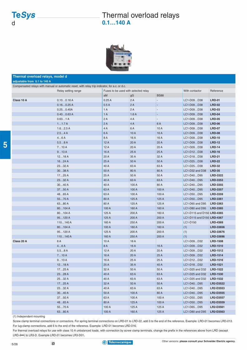
Thermal overload relays, model dadjustable from 0.1 to 140 A
Compensated relays with manual or automatic reset, with relay trip indicator, for a.c. or d.c.
Relay setting range Fuses to be used with selected relay With contactor Reference
aM gG BS88
Class 10 A 0.10…0.16 A 0.25 A 2 A - LC1-D09…D38 LRD-01
0.16…0.25 A 0.5 A 2 A - LC1-D09…D38 LRD-02
0.25…0.40A 1 A 2 A - LC1-D09…D38 LRD-03
0.40…0.63 A 1 A 1.6 A - LC1-D09…D38 LRD-04
0.63…1 A 2 A 4 A - LC1-D09…D38 LRD-05
1…1.7 A 2 A 4 A 6 A LC1-D09…D38 LRD-06
1.6…2.5 A 4 A 6 A 10 A LC1-D09…D38 LRD-07
2.5…4 A 6 A 10 A 16 A LC1-D09…D38 LRD-08
4…6 A 8 A 16 A 16 A LC1-D09…D38 LRD-10
5.5…8 A 12 A 20 A 20 A LC1-D09…D38 LRD-12
7…10 A 12 A 20 A 20 A LC1-D09…D38 LRD-14
9…13 A 16 A 25 A 25 A LC1-D12…D38 LRD-16
12…18 A 20 A 35 A 32 A LC1-D18…D38 LRD-21
16…24 A 25 A 50 A 50 A LC1-D25…D38 LRD-22
23…32 A 40 A 63 A 63 A LC1-D25…D38 LRD-32
30…38 A 50 A 80 A 80 A LC1-D32 and D38 LRD-35
17…25 A 25 A 50 A 50 A LC1-D40…D95 LRD-3322
23…32 A 40 A 63 A 63 A LC1-D40…D95 LRD-3353
30…40 A 40 A 100 A 80 A LC1-D40…D95 LRD-3355
37…50 A 63 A 100 A 100 A LC1-D40…D95 LRD-3357
48…65 A 63 A 100 A 100 A LC1-D50…D95 LRD-3359
55…70 A 80 A 125 A 125 A LC1-D50…D95 LRD-3361
63…80 A 80 A 125 A 125 A LC1-D65 and D95 LRD-3363
80…104 A 100 A 160 A 160 A LC1-D80 and D95 LRD-3365
80…104 A 125 A 200 A 160 A LC1-D115 and D150 LRD-4365
95…120 A 125 A 200 A 200 A LC1-D115 and D150 LRD-4367
110…140 A 160 A 250 A 200 A LC1-D150 LRD-4369
80…104 A 100 A 160 A 160 A (1) LRD-33656
95…120 A 125 A 200 A 200 A (1) LRD-33676
110…140 A 160 A 250 A 200 A (1) LRD-33696
Class 20 A 6 A 10 A 16 A LC1-D09…D32 LRD-1508
4…6 A 8 A 16 A 16 A LC1-D09…D32 LRD-1510
5.5…8 A 12 A 20 A 20 A LC1-D09…D32 LRD-1512
7…10 A 16 A 20 A 25 A LC1-D09…D32 LRD-1514
9…13 A 16 A 25 A 25 A LC1-D12…D32 LRD-1516
12…18 A 25 A 35 A 40 A LC1-D18…D32 LRD-1521
17…25 A 32 A 50 A 50 A LC1-D25 and D32 LRD-1522
23…28 A 40 A 63 A 63 A LC1-D25 and D32 LRD-1530
25…32 A 40 A 63 A 63 A LC1-D25 and D32 LRD-1532
17…25 A 32 A 50 A 50 A LC1-D40…D95 LR2-D3522
23…32 A 40 A 63 A 63 A LC1-D40…D95 LR2-D3553
30…40 A 50 A 100 A 80 A LC1-D40…D95 LR2-D3555
37…50 A 63 A 100 A 100 A LC1-D50…D95 LR2-D3557
48…65 A 80 A 125 A 100 A LC1-D50…D95 LR2-D3559
55…70 A 100 A 125 A 125 A LC1-D65…D95 LR2-D3561
63…80 A 100 A 160 A 125 A LC1-D80 and D95 LR2-D3563
(1) Independent mounting
Screw clamp terminal connections or connectors. For spring terminal connections on LRD-01 to LRD-22, add 3 to the end of the reference. Example: LRD-01 becomes LRD-013.
For lug-clamp connections, add 6 to the end of the reference. Example: LRD-01 becomes LRD-016.
For thermal overload relays for use with class 10 A unbalanced loads, with connection by screw clamp terminals, change the prefix in the references above from LRD (except
LRD-4•••) to LR3-D. Example LRD-01 becomes LR3-D01.
TeSysd
Thermal overload relays0.1…140 A
Other versions: please consult your Schneider Electric agency.5/27
5
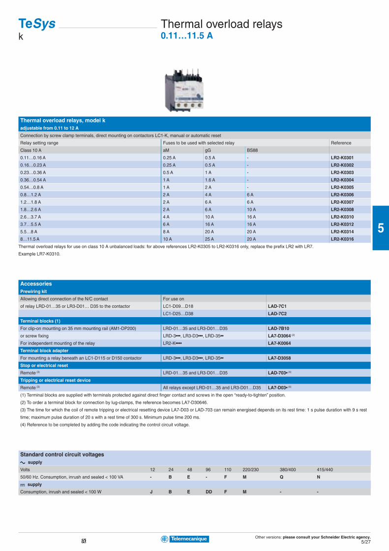
Thermal overload relays, model kadjustable from 0.11 to 12 A
Connection by screw clamp terminals, direct mounting on contactors LC1-K, manual or automatic reset
Relay setting range Fuses to be used with selected relay Reference
Class 10 A aM gG BS88
0.11…0.16 A 0.25 A 0.5 A - LR2-K0301
0.16…0.23 A 0.25 A 0.5 A - LR2-K0302
0.23…0.36 A 0.5 A 1 A - LR2-K0303
0.36…0.54 A 1 A 1.6 A - LR2-K0304
0.54…0.8 A 1 A 2 A - LR2-K0305
0.8…1.2 A 2 A 4 A 6 A LR2-K0306
1.2…1.8 A 2 A 6 A 6 A LR2-K0307
1.8…2.6 A 2 A 6 A 10 A LR2-K0308
2.6…3.7 A 4 A 10 A 16 A LR2-K0310
3.7…5.5 A 6 A 16 A 16 A LR2-K0312
5.5…8 A 8 A 20 A 20 A LR2-K0314
8…11.5 A 10 A 25 A 20 A LR2-K0316
Thermal overload relays for use on class 10 A unbalanced loads: for above references LR2-K0305 to LR2-K0316 only, replace the prefix LR2 with LR7.
Example LR7-K0310.
AccessoriesPrewiring kit
Allowing direct connection of the N/C contact For use on
of relay LRD-01…35 or LR3-D01… D35 to the contactor LC1-D09…D18 LAD-7C1
LC1-D25…D38 LAD-7C2
Terminal blocks (1)
For clip-on mounting on 35 mm mounting rail (AM1-DP200) LRD-01…35 and LR3-D01…D35 LAD-7B10
or screw fixing LRD-3•••, LR3-D3•••, LRD-35•• LA7-D3064 (2)
For independent mounting of the relay LR2-K•••• LA7-K0064
Terminal block adapter
For mounting a relay beneath an LC1-D115 or D150 contactor LRD-3•••, LR3-D3•••, LRD-35•• LA7-D3058
Stop or electrical reset
Remote (3) LRD-01…35 and LR3-D01…D35 LAD-703• (4)
Tripping or electrical reset device
Remote (3) All relays except LRD-01…35 and LR3-D01…D35 LA7-D03• (4)
(1) Terminal blocks are supplied with terminals protected against direct finger contact and screws in the open “ready-to-tighten” position.
(2) To order a terminal block for connection by lug-clamps, the reference becomes LA7-D30646.
(3) The time for which the coil of remote tripping or electrical resetting device LA7-D03 or LAD-703 can remain energised depends on its rest time: 1 s pulse duration with 9 s rest
time; maximum pulse duration of 20 s with a rest time of 300 s. Minimum pulse time 200 ms.
(4) Reference to be completed by adding the code indicating the control circuit voltage.
Standard control circuit voltagesc c c c c supply
Volts 12 24 48 96 110 220/230 380/400 415/440
50/60 Hz. Consumption, inrush and sealed < 100 VA - B E - F M Q N
a a a a a supply
Consumption, inrush and sealed < 100 W J B E DD F M - -
TeSysk
Thermal overload relays0.11…11.5 A
Other versions: please consult your Schneider Electric agency.5/28
5
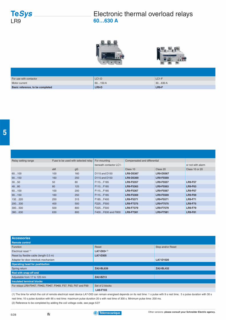
For use with contactor LC1-D LC1-F
Motor current 60…150 A 30…630 A
Basic reference, to be completed LR9-D LR9-F
Relay setting range Fuse to be used with selected relay For mounting Compensated and differential
beneath contactor LC1- or not with alarm
aM gG Class 10 Class 20 Class 10 or 20
60…100 100 160 D115 and D150 LR9-D5367 LR9-D5567
90…150 160 250 D115 and D150 LR9-D5369 LR9-F5569
30…50 50 80 F115…F185 LR9-F5357 LR9-F5557 LR9-F57
48…80 80 125 F115…F185 LR9-F5363 LR9-F5563 LR9-F63
60…100 100 200 F115…F185 LR9-F5367 LR9-F5567 LR9-F67
90…150 160 250 F115…F185 LR9-F5369 LR9-F5569 LR9-F69
132…220 250 315 F185…F400 LR9-F5371 LR9-F5571 LR9-F71
200…330 400 500 F225…F500 LR9-F7375 LR9-F7575 LR9-F75
300…500 500 800 F225…F500 LR9-F7379 LR9-F7579 LR9-F79
380…630 630 800 F400…F630 and F800 LR9-F7381 LR9-F7581 LR9-F81
AccessoriesRemote control
Function Reset Stop and/or Reset
Electrical reset (1) LA7-D03• (2)
Reset by flexible cable (length 0.5 m) LA7-D305
Adapter for door interlock mechanism LA7-D1020
Operating head for pushbutton
Spring return ZA2-BL639 ZA2-BL432
Rod with snap-off end
Adjustable from 17 to 120 mm ZA2-BZ13
Insulated terminal blocks
For relays LR9-F5•57, F5•63, F5•67, F5•69, F57, F63, F67 and F69 Set of 2 blocks
LA9-F103
(1) The time for which the coil of remote electrical reset device LA7-D03 can remain energised depends on its rest time: 1 s pulse with 9 s rest time; 5 s pulse duration with 30 s
rest time; 10 s pulse duration with 90 s rest time: maximum pulse duration 20 s with rest time of 300 s. Minimum pulse time: 200 ms.
(2) Reference to be completed by adding the coil voltage code, see page 5/27
TeSysLR9
Electronic thermal overload relays60…630 A
Other versions: please consult your Schneider Electric agency.5/29
5
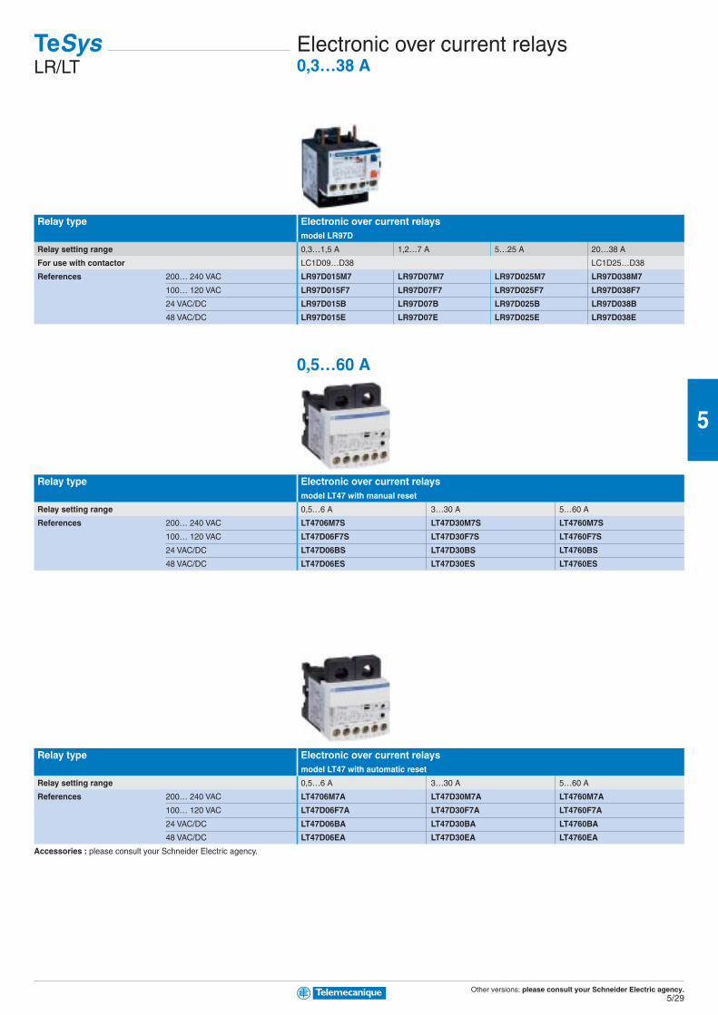
Relay type Electronic over current relaysmodel LR97D
Relay setting range 0,3…1,5 A 1,2…7 A 5…25 A 20…38 A
For use with contactor LC1D09…D38 LC1D25…D38
References 200… 240 VAC LR97D015M7 LR97D07M7 LR97D025M7 LR97D038M7
100… 120 VAC LR97D015F7 LR97D07F7 LR97D025F7 LR97D038F7
24 VAC/DC LR97D015B LR97D07B LR97D025B LR97D038B
48 VAC/DC LR97D015E LR97D07E LR97D025E LR97D038E
0,5…60 A
Relay type Electronic over current relaysmodel LT47 with manual reset
Relay setting range 0,5…6 A 3…30 A 5…60 A
References 200… 240 VAC LT4706M7S LT47D30M7S LT4760M7S
100… 120 VAC LT47D06F7S LT47D30F7S LT4760F7S
24 VAC/DC LT47D06BS LT47D30BS LT4760BS
48 VAC/DC LT47D06ES LT47D30ES LT4760ES
Relay type Electronic over current relaysmodel LT47 with automatic reset
Relay setting range 0,5…6 A 3…30 A 5…60 A
References 200… 240 VAC LT4706M7A LT47D30M7A LT4760M7A
100… 120 VAC LT47D06F7A LT47D30F7A LT4760F7A
24 VAC/DC LT47D06BA LT47D30BA LT4760BA
48 VAC/DC LT47D06EA LT47D30EA LT4760EA
Accessories : please consult your Schneider Electric agency.
TeSysLR/LT
Electronic over current relays0,3…38 A
Other versions: please consult your Schneider Electric agency.5/30
5
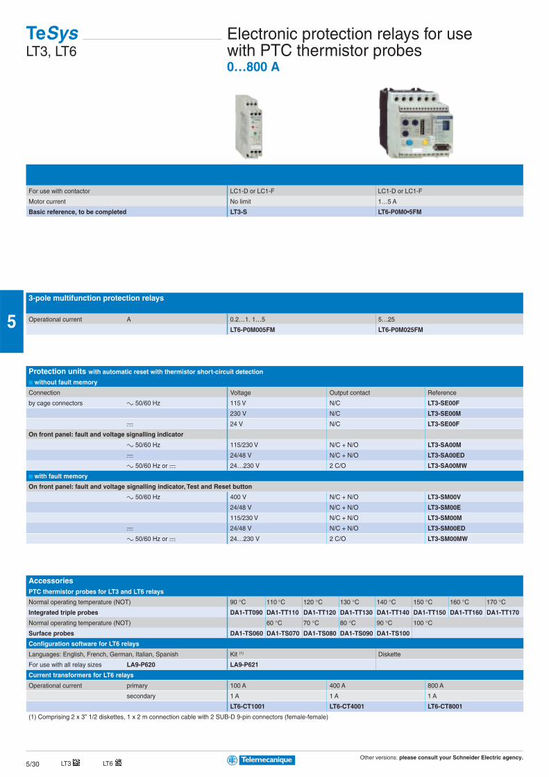
For use with contactor LC1-D or LC1-F LC1-D or LC1-F
Motor current No limit 1…5 A
Basic reference, to be completed LT3-S LT6-P0M0•5FM
3-pole multifunction protection relays
Operational current A 0.2…1. 1…5 5…25
LT6-P0M005FM LT6-P0M025FM
Protection units with automatic reset with thermistor short-circuit detection
■ without fault memory
Connection Voltage Output contact Reference
by cage connectors c 50/60 Hz 115 V N/C LT3-SE00F
230 V N/C LT3-SE00M
a 24 V N/C LT3-SE00F
On front panel: fault and voltage signalling indicator
c 50/60 Hz 115/230 V N/C + N/O LT3-SA00M
a 24/48 V N/C + N/O LT3-SA00ED
c 50/60 Hz or a 24…230 V 2 C/O LT3-SA00MW
■ with fault memory
On front panel: fault and voltage signalling indicator, Test and Reset button
c 50/60 Hz 400 V N/C + N/O LT3-SM00V
24/48 V N/C + N/O LT3-SM00E
115/230 V N/C + N/O LT3-SM00M
a 24/48 V N/C + N/O LT3-SM00ED
c 50/60 Hz or a 24…230 V 2 C/O LT3-SM00MW
AccessoriesPTC thermistor probes for LT3 and LT6 relays
Normal operating temperature (NOT) 90 °C 110 °C 120 °C 130 °C 140 °C 150 °C 160 °C 170 °CIntegrated triple probes DA1-TT090 DA1-TT110 DA1-TT120 DA1-TT130 DA1-TT140 DA1-TT150 DA1-TT160 DA1-TT170
Normal operating temperature (NOT) 60 °C 70 °C 80 °C 90 °C 100 °CSurface probes DA1-TS060 DA1-TS070 DA1-TS080 DA1-TS090 DA1-TS100
Configuration software for LT6 relays
Languages: English, French, German, Italian, Spanish Kit (1) Diskette
For use with all relay sizes LA9-P620 LA9-P621
Current transformers for LT6 relays
Operational current primary 100 A 400 A 800 A
secondary 1 A 1 A 1 A
LT6-CT1001 LT6-CT4001 LT6-CT8001
(1) Comprising 2 x 3” 1/2 diskettes, 1 x 2 m connection cable with 2 SUB-D 9-pin connectors (female-female)
TeSysLT3, LT6
Electronic protection relays for usewith PTC thermistor probes0…800 A
LT6LT3
Other versions: please consult your Schneider Electric agency.5/31
5
1/L1
2/T
1
3/L2
4/T
2
5/L3
6/T
3
1/L1
2/T
1
3/L2
4/T
2
5/L3
6/T
3
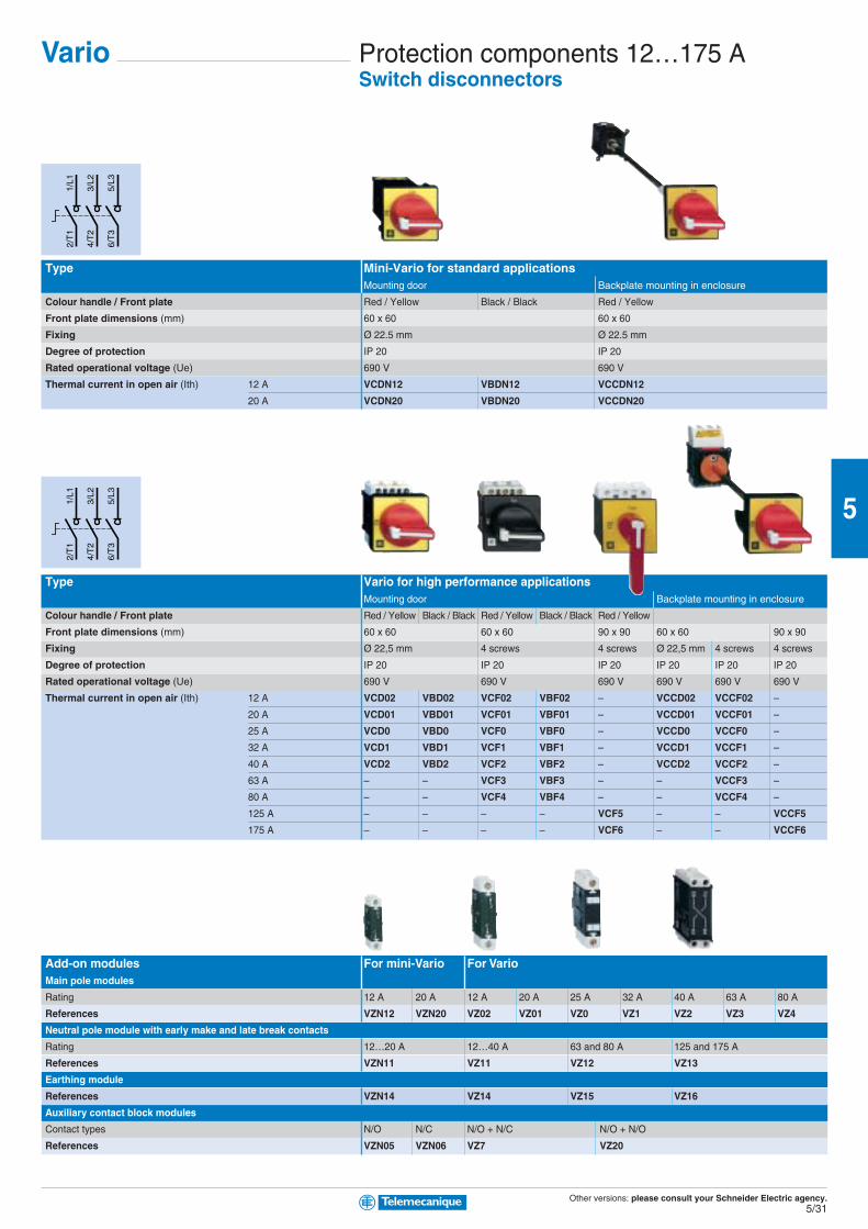
Vario Protection components 12…175 ASwitch disconnectors
Type Mini-Vario for standard applicationsMounting door Backplate mounting in enclosure
Colour handle / Front plate Red / Yellow Black / Black Red / Yellow
Front plate dimensions (mm) 60 x 60 60 x 60
Fixing Ø 22.5 mm Ø 22.5 mm
Degree of protection IP 20 IP 20
Rated operational voltage (Ue) 690 V 690 V
Thermal current in open air (Ith) 12 A VCDN12 VBDN12 VCCDN12
20 A VCDN20 VBDN20 VCCDN20
Type Vario for high performance applicationsMounting door Backplate mounting in enclosure
Colour handle / Front plate Red / Yellow Black / Black Red / Yellow Black / Black Red / Yellow
Front plate dimensions (mm) 60 x 60 60 x 60 90 x 90 60 x 60 90 x 90
Fixing Ø 22,5 mm 4 screws 4 screws Ø 22,5 mm 4 screws 4 screws
Degree of protection IP 20 IP 20 IP 20 IP 20 IP 20 IP 20
Rated operational voltage (Ue) 690 V 690 V 690 V 690 V 690 V 690 V
Thermal current in open air (Ith) 12 A VCD02 VBD02 VCF02 VBF02 – VCCD02 VCCF02 –
20 A VCD01 VBD01 VCF01 VBF01 – VCCD01 VCCF01 –
25 A VCD0 VBD0 VCF0 VBF0 – VCCD0 VCCF0 –
32 A VCD1 VBD1 VCF1 VBF1 – VCCD1 VCCF1 –
40 A VCD2 VBD2 VCF2 VBF2 – VCCD2 VCCF2 –
63 A – – VCF3 VBF3 – – VCCF3 –
80 A – – VCF4 VBF4 – – VCCF4 –
125 A – – – – VCF5 – – VCCF5
175 A – – – – VCF6 – – VCCF6
Add-on modules For mini-Vario For VarioMain pole modules
Rating 12 A 20 A 12 A 20 A 25 A 32 A 40 A 63 A 80 A
References VZN12 VZN20 VZ02 VZ01 VZ0 VZ1 VZ2 VZ3 VZ4
Neutral pole module with early make and late break contacts
Rating 12…20 A 12…40 A 63 and 80 A 125 and 175 A
References VZN11 VZ11 VZ12 VZ13
Earthing module
References VZN14 VZ14 VZ15 VZ16
Auxiliary contact block modules
Contact types N/O N/C N/O + N/C N/O + N/O
References VZN05 VZN06 VZ7 VZ20
Other versions: please consult your Schneider Electric agency.5/32
5
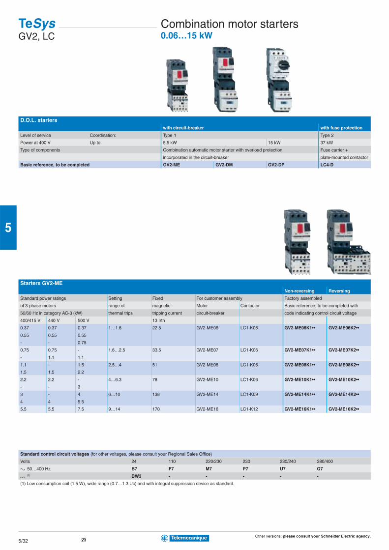
D.O.L. starterswith circuit-breaker with fuse protection
Level of service Coordination: Type 1 Type 2
Power at 400 V Up to: 5.5 kW 15 kW 37 kW
Type of components Combination automatic motor starter with overload protection Fuse carrier +
incorporated in the circuit-breaker plate-mounted contactor
Basic reference, to be completed GV2-ME GV2-DM GV2-DP LC4-D
Starters GV2-MENon-reversing Reversing
Standard power ratings Setting Fixed For customer assembly Factory assembled
of 3-phase motors range of magnetic Motor Contactor Basic reference, to be completed with
50/60 Hz in category AC-3 (kW) thermal trips tripping current circuit-breaker code indicating control circuit voltage
400/415 V 440 V 500 V 13 Irth
0.37 0.37 0.37 1…1.6 22.5 GV2-ME06 LC1-K06 GV2-ME06K1•• GV2-ME06K2••
0.55 0.55 0.55
- - 0.75
0.75 0.75 - 1.6…2.5 33.5 GV2-ME07 LC1-K06 GV2-ME07K1•• GV2-ME07K2••
- 1.1 1.1
1.1 - 1.5 2.5…4 51 GV2-ME08 LC1-K06 GV2-ME08K1•• GV2-ME08K2••
1.5 1.5 2.2
2.2 2.2 - 4…6.3 78 GV2-ME10 LC1-K06 GV2-ME10K1•• GV2-ME10K2••
- - 3
3 - 4 6…10 138 GV2-ME14 LC1-K09 GV2-ME14K1•• GV2-ME14K2••
4 4 5.5
5.5 5.5 7.5 9…14 170 GV2-ME16 LC1-K12 GV2-ME16K1•• GV2-ME16K2••
Standard control circuit voltages (for other voltages, please consult your Regional Sales Office)
Volts 24 110 220/230 230 230/240 380/400
c 50…400 Hz B7 F7 M7 P7 U7 Q7
a (1) BW3 - - - - -
(1) Low consumption coil (1.5 W), wide range (0.7…1.3 Uc) and with integral suppression device as standard.
TeSysGV2, LC
Combination motor starters0.06…15 kW
Other versions: please consult your Schneider Electric agency.5/33
5
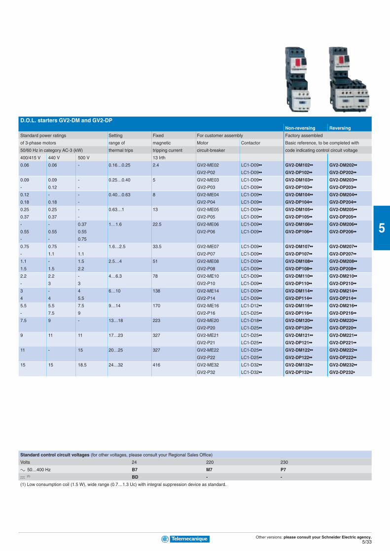
D.O.L. starters GV2-DM and GV2-DPNon-reversing Reversing
Standard power ratings Setting Fixed For customer assembly Factory assembled
of 3-phase motors range of magnetic Motor Contactor Basic reference, to be completed with
50/60 Hz in category AC-3 (kW) thermal trips tripping current circuit-breaker code indicating control circuit voltage
400/415 V 440 V 500 V 13 Irth
0.06 0.06 - 0.16…0.25 2.4 GV2-ME02 LC1-D09•• GV2-DM102•• GV2-DM202••
GV2-P02 LC1-D09•• GV2-DP102•• GV2-DP202••
0.09 0.09 - 0.25…0.40 5 GV2-ME03 LC1-D09•• GV2-DM103•• GV2-DM203••
- 0.12 - GV2-P03 LC1-D09•• GV2-DP103•• GV2-DP203••
0.12 - - 0.40…0.63 8 GV2-ME04 LC1-D09•• GV2-DM104•• GV2-DM204••
0.18 0.18 - GV2-P04 LC1-D09•• GV2-DP104•• GV2-DP204••
0.25 0.25 - 0.63…1 13 GV2-ME05 LC1-D09•• GV2-DM105•• GV2-DM205••
0.37 0.37 - GV2-P05 LC1-D09•• GV2-DP105•• GV2-DP205••
- - 0.37 1…1.6 22.5 GV2-ME06 LC1-D09•• GV2-DM106•• GV2-DM206••
0.55 0.55 0.55 GV2-P06 LC1-D09•• GV2-DP106•• GV2-DP206••
- - 0.75
0.75 0.75 - 1.6…2.5 33.5 GV2-ME07 LC1-D09•• GV2-DM107•• GV2-DM207••
- 1.1 1.1 GV2-P07 LC1-D09•• GV2-DP107•• GV2-DP207••
1.1 - 1.5 2.5…4 51 GV2-ME08 LC1-D09•• GV2-DM108•• GV2-DM208••
1.5 1.5 2.2 GV2-P08 LC1-D09•• GV2-DP108•• GV2-DP208••
2.2 2.2 - 4…6.3 78 GV2-ME10 LC1-D09•• GV2-DM110•• GV2-DM210••
- 3 3 GV2-P10 LC1-D09•• GV2-DP110•• GV2-DP210••
3 - 4 6…10 138 GV2-ME14 LC1-D09•• GV2-DM114•• GV2-DM214••
4 4 5.5 GV2-P14 LC1-D09•• GV2-DP114•• GV2-DP214••
5.5 5.5 7.5 9…14 170 GV2-ME16 LC1-D12•• GV2-DM116•• GV2-DM216••
- 7.5 9 GV2-P16 LC1-D25•• GV2-DP116•• GV2-DP216••
7.5 9 - 13…18 223 GV2-ME20 LC1-D18•• GV2-DM120•• GV2-DM220••
GV2-P20 LC1-D25•• GV2-DP120•• GV2-DP220••
9 11 11 17…23 327 GV2-ME21 LC1-D25•• GV2-DM121•• GV2-DM221••
GV2-P21 LC1-D25•• GV2-DP121•• GV2-DP221••
11 - 15 20…25 327 GV2-ME22 LC1-D25•• GV2-DM122•• GV2-DM222••
GV2-P22 LC1-D25•• GV2-DP122•• GV2-DP222••
15 15 18.5 24…32 416 GV2-ME32 LC1-D32•• GV2-DM132•• GV2-DM232••
GV2-P32 LC1-D32•• GV2-DP132•• GV2-DP232•
Standard control circuit voltages (for other voltages, please consult your Regional Sales Office)
Volts 24 220 230
c 50…400 Hz B7 M7 P7
a (1) BD - -
(1) Low consumption coil (1.5 W), wide range (0.7…1.3 Uc) with integral suppression device as standard.
Other versions: please consult your Schneider Electric agency.5/34
5
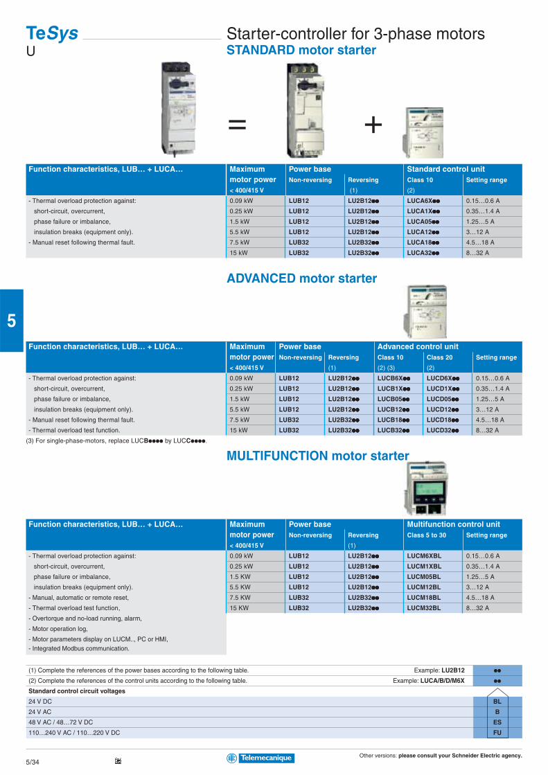
= +Function characteristics, LUB… + LUCA… Maximum Power base Standard control unit
motor power Non-reversing Reversing Class 10 Setting range
< 400/415 V (1) (2)
- Thermal overload protection against: 0.09 kW LUB12 LU2B12pppppppppp LUCA6Xpppppppppp 0.15…0.6 A
short-circuit, overcurrent, 0.25 kW LUB12 LU2B12pppppppppp LUCA1Xpppppppppp 0.35…1.4 A
phase failure or imbalance, 1.5 kW LUB12 LU2B12pppppppppp LUCA05pppppppppp 1.25…5 A
insulation breaks (equipment only). 5.5 kW LUB12 LU2B12pppppppppp LUCA12pppppppppp 3…12 A
- Manual reset following thermal fault. 7.5 kW LUB32 LU2B32pppppppppp LUCA18pppppppppp 4.5…18 A
15 kW LUB32 LU2B32pppppppppp LUCA32pppppppppp 8…32 A
ADVANCED motor starter
Function characteristics, LUB… + LUCA… Maximum Power base Advanced control unitmotor power Non-reversing Reversing Class 10 Class 20 Setting range
< 400/415 V (1) (2) (3) (2)
- Thermal overload protection against: 0.09 kW LUB12 LU2B12pppppppppp LUCB6Xpppppppppp LUCD6Xpppppppppp 0.15…0.6 A
short-circuit, overcurrent, 0.25 kW LUB12 LU2B12pppppppppp LUCB1Xpppppppppp LUCD1Xpppppppppp 0.35…1.4 A
phase failure or imbalance, 1.5 kW LUB12 LU2B12pppppppppp LUCB05pppppppppp LUCD05pppppppppp 1.25…5 A
insulation breaks (equipment only). 5.5 kW LUB12 LU2B12pppppppppp LUCB12pppppppppp LUCD12pppppppppp 3…12 A
- Manual reset following thermal fault. 7.5 kW LUB32 LU2B32pppppppppp LUCB18pppppppppp LUCD18pppppppppp 4.5…18 A
- Thermal overload test function. 15 kW LUB32 LU2B32pppppppppp LUCB32pppppppppp LUCD32pppppppppp 8…32 A
(3) For single-phase-motors, replace LUCBpppp by LUCCpppp.
MULTIFUNCTION motor starter
Function characteristics, LUB… + LUCA… Maximum Power base Multifunction control unitmotor power Non-reversing Reversing Class 5 to 30 Setting range
< 400/415 V (1)
- Thermal overload protection against: 0.09 kW LUB12 LU2B12pppppppppp LUCM6XBL 0.15…0.6 A
short-circuit, overcurrent, 0.25 kW LUB12 LU2B12pppppppppp LUCM1XBL 0.35…1.4 A
phase failure or imbalance, 1.5 KW LUB12 LU2B12pppppppppp LUCM05BL 1.25…5 A
insulation breaks (equipment only). 5.5 KW LUB12 LU2B12pppppppppp LUCM12BL 3…12 A
- Manual, automatic or remote reset, 7.5 KW LUB32 LU2B32pppppppppp LUCM18BL 4.5…18 A
- Thermal overload test function, 15 KW LUB32 LU2B32pppppppppp LUCM32BL 8…32 A
- Overtorque and no-load running, alarm,
- Motor operation log,
- Motor parameters display on LUCM.., PC or HMI,- Integrated Modbus communication.
(1) Complete the references of the power bases according to the following table. Example: LU2B12 pp
(2) Complete the references of the control units according to the following table. Example: LUCA/B/D/M6X pp
Standard control circuit voltages
24 V DC BL
24 V AC B
48 V AC / 48…72 V DC ES
110…240 V AC / 110…220 V DC FU
TeSysU
Starter-controller for 3-phase motorsSTANDARD motor starter
Other versions: please consult your Schneider Electric agency.5/35
5
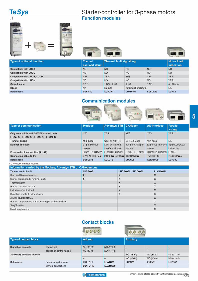
=+Type of optional function Thermal Thermal fault signalling Motor load
overload alarm indicationCompatible with LUCA NO NO NO NO NO
Compatible with LUCL NO NO NO NO NO
Compatible with LUCB, LUCD YES YES YES YES YES
Compatible with LUCM NO NO NO NO YES
Output signal 1 NO 1 NO +1 NC 1 NC 1 NO 4…20 mA
Reset NA Manual Automatic or remote NA
References LUFW10 LUFDH11 LUFDA01 LUFDA10 LUFV2
Communication modules
Type of communication Modbus Advantys STB CANopen AS-Interface Parallelwiring
Only compatible with 24 V DC control units YES YES YES YES YES
LUCA..BL, LUCB..BL, LUCD..BL, LUCM..BL
Transfer speed 19.2 Kbps Dpg. on NIM (1) 20 K…1 Mbps 167 Kbps NA
Number of slaves 31 per Modbus Dpg. on Network 128 per CANopen 62 per AS-Interface 8 per LU9GC02
master Interface Module module master splitter box
Pre-wired coil connection (A1 A2) LU9BN11C, LU9MRC LU9BN11L, LU9MRL LU9BN11L, LU9MRL LU9BN11C, LU9MRC LU9Rxx
Connecting cable to PC VW3 A8 306 Rpp LU9RCDpp,LU9RDDpp TSXCANCpp XZCG0142 TSXCDPppp
References LUFC033 LULC15 LULC08 ASILUFC51 LUFC00
(1) Network Interface Module.
Information carried by the Modbus, Advantys STB or CANopen busType of control unit LUCAppppppppppBL LUCBppppppppppBL, LUCDppppppppppBL LUCMppppppppppBL
Start and Stop commands X X X
Starter status (ready, running, fault) X X X
Thermal alarm X X
Remote reset via the bus X X
Indication of motor load X X
Signalling and fault differentiation X X
Alarms (overcurrent, …) X
Remote programming and monitoring of all the functions X
“Log” function X
Monitoring function X
Contact blocks
Type of contact block Add-on Auxiliary
Signalling contacts of any fault NC (95-96) NO (97-98) – – –
position of control handle NO (17-18) NO (17-18) – – –
2 auxiliary contacts module – – NO (33-34) NC (31-32) NC (31-32)
– – NO (43-44) NO (43-44) NC (41-42)
References Screw clamp terminals LUA1C11 LUA1C20 LUFN20 LUFN11 LUFN02
Without connections LUA1C110 LUA1C200 – – –
TeSysU
Starter-controller for 3-phase motorsFunction modules
Other versions: please consult your Schneider Electric agency.5/36
5
= +
TeSys GV3L
TeSys LC1DContactor
Circuit-breakers
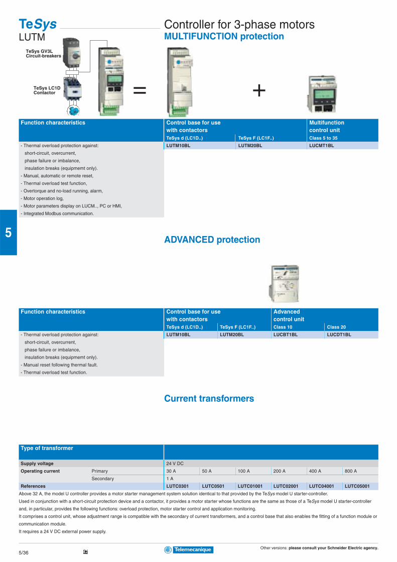
TeSysLUTM
Controller for 3-phase motorsMULTIFUNCTION protection
Function characteristics Control base for use Multifunctionwith contactors control unitTeSys d (LC1D..) TeSys F (LC1F..) Class 5 to 35
- Thermal overload protection against: LUTM10BL LUTM20BL LUCMT1BL
short-circuit, overcurrent,
phase failure or imbalance,
insulation breaks (equipmemt only).
- Manual, automatic or remote reset,
- Thermal overload test function,
- Overtorque and no-load running, alarm,
- Motor operation log,
- Motor parameters display on LUCM.., PC or HMI,
- Integrated Modbus communication.
ADVANCED protection
Function characteristics Control base for use Advancedwith contactors control unitTeSys d (LC1D..) TeSys F (LC1F..) Class 10 Class 20
- Thermal overload protection against: LUTM10BL LUTM20BL LUCBT1BL LUCDT1BL
short-circuit, overcurrent,
phase failure or imbalance,
insulation breaks (equipmemt only).
- Manual reset following thermal fault.
- Thermal overload test function.
Current transformers
Type of transformer
Supply voltage 24 V DC
Operating current Primary 30 A 50 A 100 A 200 A 400 A 800 A
Secondary 1 A
References LUTC0301 LUTC0501 LUTC01001 LUTC02001 LUTC04001 LUTC05001
Above 32 A, the model U controller provides a motor starter management system solution identical to that provided by the TeSys model U starter-controller.
Used in conjunction with a short-circuit protection device and a contactor, it provides a motor starter whose functions are the same as those of a TeSys model U starter-controller
and, in particular, provides the following functions: overload protection, motor starter control and application monitoring.
It comprises a control unit, whose adjustment range is compatible with the secondary of current transformers, and a control base that also enables the fitting of a function module or
communication module.
It requires a 24 V DC external power supply.
Other versions: please consult your Schneider Electric agency.5/37
5
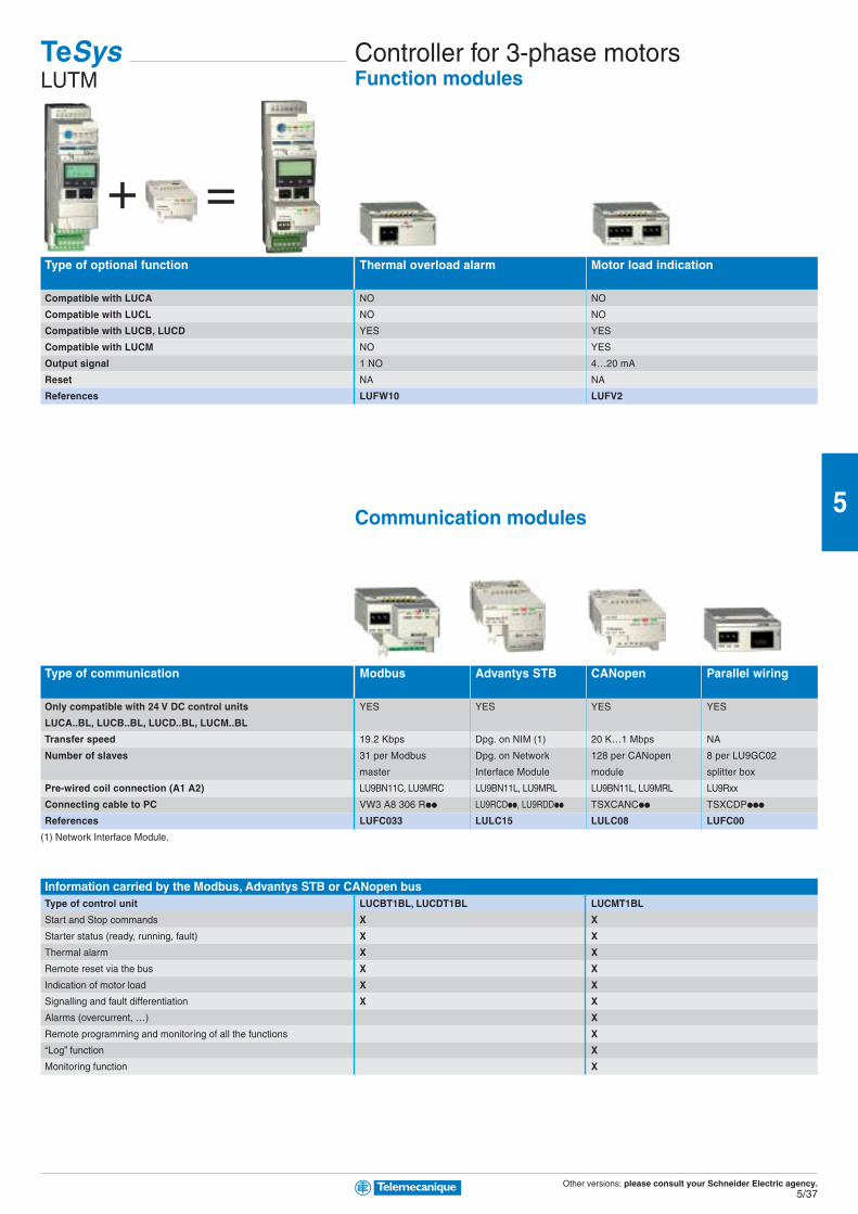
=+Type of optional function Thermal overload alarm Motor load indication
Compatible with LUCA NO NO
Compatible with LUCL NO NO
Compatible with LUCB, LUCD YES YES
Compatible with LUCM NO YES
Output signal 1 NO 4…20 mA
Reset NA NA
References LUFW10 LUFV2
Communication modules
Type of communication Modbus Advantys STB CANopen Parallel wiring
Only compatible with 24 V DC control units YES YES YES YES
LUCA..BL, LUCB..BL, LUCD..BL, LUCM..BL
Transfer speed 19.2 Kbps Dpg. on NIM (1) 20 K…1 Mbps NA
Number of slaves 31 per Modbus Dpg. on Network 128 per CANopen 8 per LU9GC02
master Interface Module module splitter box
Pre-wired coil connection (A1 A2) LU9BN11C, LU9MRC LU9BN11L, LU9MRL LU9BN11L, LU9MRL LU9Rxx
Connecting cable to PC VW3 A8 306 Rpp LU9RCDpp, LU9RDDpp TSXCANCpp TSXCDPppp
References LUFC033 LULC15 LULC08 LUFC00
(1) Network Interface Module.
Information carried by the Modbus, Advantys STB or CANopen busType of control unit LUCBT1BL, LUCDT1BL LUCMT1BL
Start and Stop commands X X
Starter status (ready, running, fault) X X
Thermal alarm X X
Remote reset via the bus X X
Indication of motor load X X
Signalling and fault differentiation X X
Alarms (overcurrent, …) X
Remote programming and monitoring of all the functions X
“Log” function X
Monitoring function X
TeSysLUTM
Controller for 3-phase motorsFunction modules
Other versions: please consult your Schneider Electric agency.5/38
5
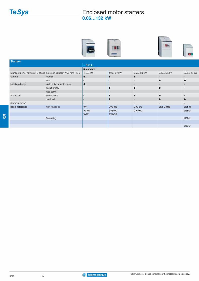
Starters■ D.O.L.■ standard
Standard power ratings of 3-phase motors in category AC3 400/415 V 4…37 kW 0.06…37 kW 0.55…30 kW 0.37…5.5 kW 0.25…45 kW
Starters manual ● ● ● - -
auto - - - ● ●
Isolating device switch-disconnector-fuse ● - - - -
circuit-breaker - ● ● ● -
fuse carrier - - - - -
Protection short-circuit - ● ● ● -
overload - ● - ● ●
Communication - - - - -
Basic reference Non reversing V•F GV2-ME GV2-LC LE1-GVME LE1-M
VCFN GV3-PC GV-NGC LE1-D
V•FX GV3-CE
Reversing LE2-K
LE2-D
TeSys Enclosed motor starters0.06…132 kW
Other versions: please consult your Schneider Electric agency.5/39
5
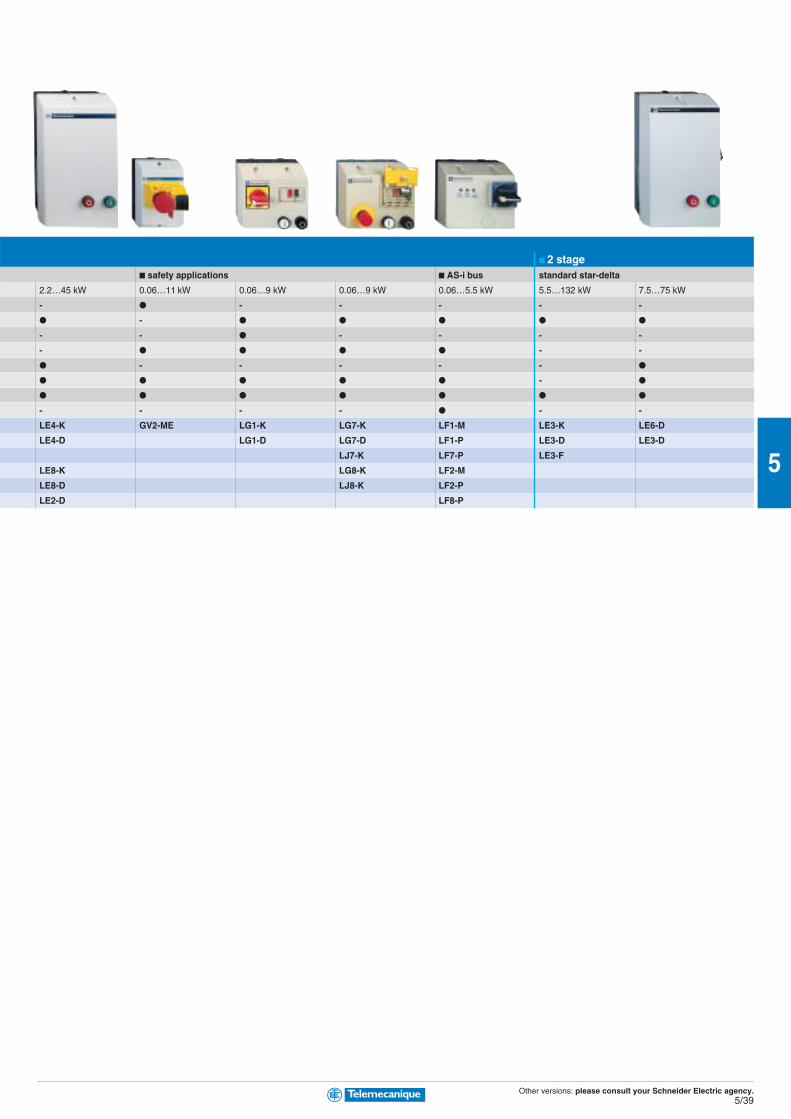
■ 2 stage■ safety applications ■ AS-i bus standard star-delta
2.2…45 kW 0.06…11 kW 0.06…9 kW 0.06…9 kW 0.06…5.5 kW 5.5…132 kW 7.5…75 kW
- ● - - - - -
● - ● ● ● ● ●
- - ● - - - -
- ● ● ● ● - -
● - - - - - ●
● ● ● ● ● - ●
● ● ● ● ● ● ●
- - - - ● - -
LE4-K GV2-ME LG1-K LG7-K LF1-M LE3-K LE6-D
LE4-D LG1-D LG7-D LF1-P LE3-D LE3-D
LJ7-K LF7-P LE3-F
LE8-K LG8-K LF2-M
LE8-D LJ8-K LF2-P
LE2-D LF8-P
Other versions: please consult your Schneider Electric agency.5/40
5
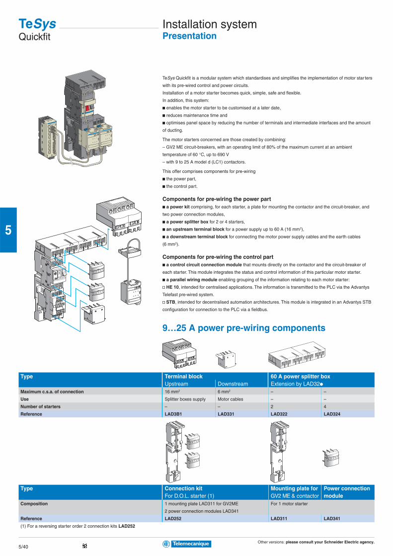
TeSysQuickfit
Installation systemPresentation
TeSys Quickfit is a modular system which standardises and simplifies the implementation of motor star ters
with its pre-wired control and power circuits.
Installation of a motor starter becomes quick, simple, safe and flexible.
In addition, this system:
b enables the motor starter to be customised at a later date,
b reduces maintenance time and
b optimises panel space by reducing the number of terminals and intermediate interfaces and the amount
of ducting.
The motor starters concerned are those created by combining:
– GV2 ME circuit-breakers, with an operating limit of 80% of the maximum current at an ambient
temperature of 60 °C, up to 690 V
– with 9 to 25 A model d (LC1) contactors.
This offer comprises components for pre-wiring
b the power part,
b the control part.
Components for pre-wiring the power partb a power kit comprising, for each starter, a plate for mounting the contactor and the circuit-breaker, and
two power connection modules,
b a power splitter box for 2 or 4 starters,
b an upstream terminal block for a power supply up to 60 A (16 mm2),
b a downstream terminal block for connecting the motor power supply cables and the earth cables
(6 mm2).
Components for pre-wiring the control partb a control circuit connection module that mounts directly on the contactor and the circuit-breaker of
each starter. This module integrates the status and control information of this particular motor starter.
b a parallel wiring module enabling grouping of the information relating to each motor starter:
v HE 10, intended for centralised applications. The information is transmitted to the PLC via the Advantys
Telefast pre-wired system.
v STB, intended for decentralised automation architectures. This module is integrated in an Advantys STB
configuration for connection to the PLC via a fieldbus.
9…25 A power pre-wiring components
Type Terminal block 60 A power splitter boxUpstream Downstream Extension by LAD32p
Maximum c.s.a. of connection 16 mm2 6 mm2 – –
Use Splitter boxes supply Motor cables – –
Number of starters – – 2 4
Reference LAD3B1 LAD331 LAD322 LAD324
Type Connection kit Mounting plate for Power connectionFor D.O.L. starter (1) GV2 ME & contactor module
Composition 1 mounting plate LAD311 for GV2ME For 1 motor starter
2 power connection modules LAD341
Reference LAD252 LAD311 LAD341
(1) For a reversing starter order 2 connection kits LAD252

Other versions: please consult your Schneider Electric agency.5/41
5
Type Connection module
Model d coil voltage 12…250 V AC or 5…130 V DC 24 V DC
Type of coil control relay Electronic Without relay
Type of motor starter Direct Reversing Direct Reversing
Reference LAD9AP31 LAD9AP32 LAD9AP3D1 LAD9AP3D2
Type 24 V DC parallel wiring moduleSplitter box Advantys STB parallel interface module
PLC/motor starter side connectors 2 x HE10/8 x RJ45 –/4 x RJ45
Reference LU9G02 STBEPI2145
Accessories
Type Connecting cables(1) From splitter box LU9G02 to the PLC
Connectors 2 x RJ45 2 HE10 Bare wires and HE10
Gauge / c.s.a. – 22 / 0.324 mm2 28 / 0.080 mm2 22 / 0.324 mm2
Reference L = 0.3 m LU9R03 – – –
0.5 m – TSXCDP053 – –
1 m LU9R10 TSXCDP103 ABFH20H100 –
2 m – TSXCDP203 ABFH20H200 –
3 m LU9R30 TSXCDP303 ABFH20H300 TSXCDP301
5 m – TSXCDP503 – TSXCDP301
(1) From connection module LAD9AP3p to splitter box LU9G02 or module STBEPI2145
Type Connectors Connecting cableSpring terminals Self-stripping
Use External contact, auxiliary power supply Between communication module APP1Cp and
splitter box LU9GG02
Reference APE1PRE21 APE1PAD21 APP2AH40H060
Control-command pre-wiring components
Other versions: please consult your Schneider Electric agency.5/42
5
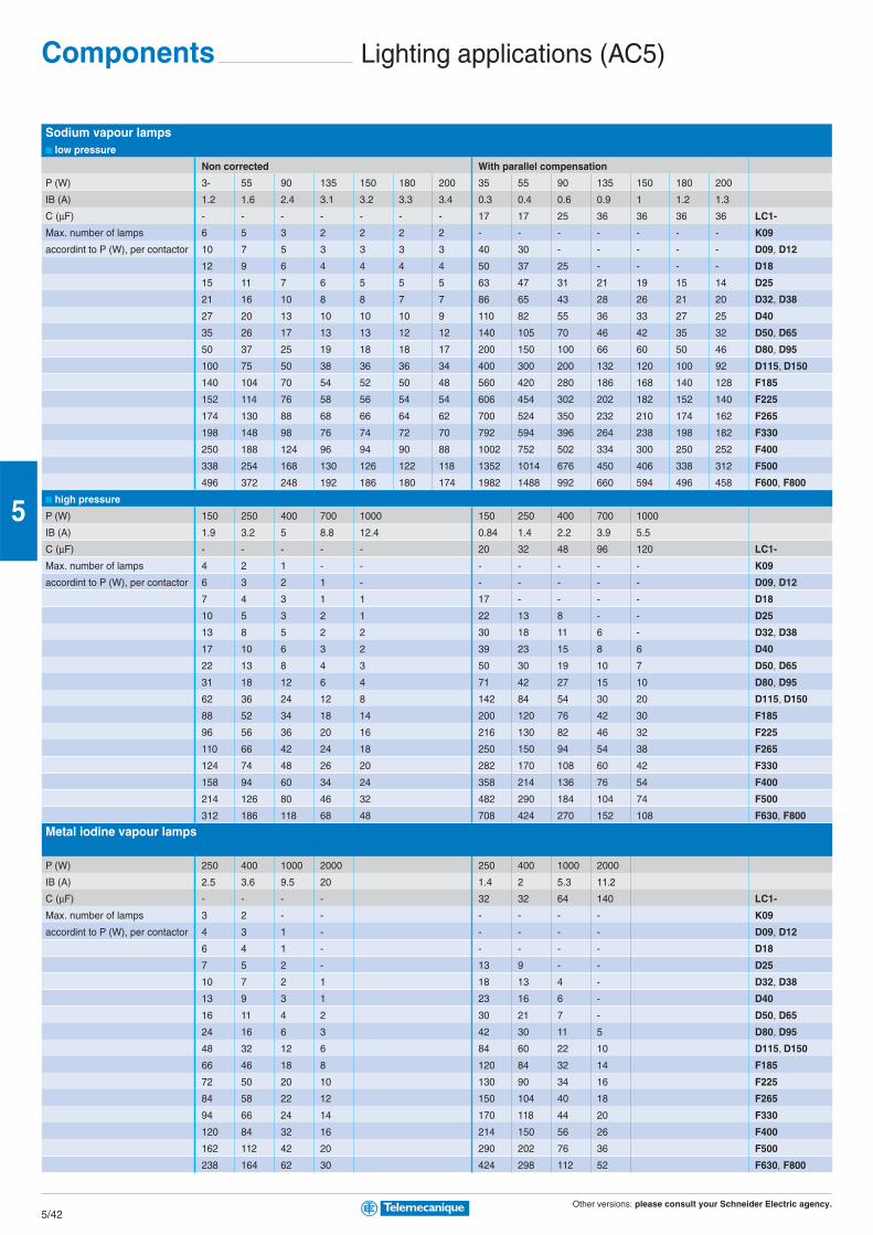
Sodium vapour lamps■ low pressure
Non corrected With parallel compensation
P (W) 3- 55 90 135 150 180 200 35 55 90 135 150 180 200
IB (A) 1.2 1.6 2.4 3.1 3.2 3.3 3.4 0.3 0.4 0.6 0.9 1 1.2 1.3
C (µF) - - - - - - - 17 17 25 36 36 36 36 LC1-
Max. number of lamps 6 5 3 2 2 2 2 - - - - - - - K09
accordint to P (W), per contactor 10 7 5 3 3 3 3 40 30 - - - - - D09, D12
12 9 6 4 4 4 4 50 37 25 - - - - D18
15 11 7 6 5 5 5 63 47 31 21 19 15 14 D25
21 16 10 8 8 7 7 86 65 43 28 26 21 20 D32, D38
27 20 13 10 10 10 9 110 82 55 36 33 27 25 D40
35 26 17 13 13 12 12 140 105 70 46 42 35 32 D50, D65
50 37 25 19 18 18 17 200 150 100 66 60 50 46 D80, D95
100 75 50 38 36 36 34 400 300 200 132 120 100 92 D115, D150
140 104 70 54 52 50 48 560 420 280 186 168 140 128 F185
152 114 76 58 56 54 54 606 454 302 202 182 152 140 F225
174 130 88 68 66 64 62 700 524 350 232 210 174 162 F265
198 148 98 76 74 72 70 792 594 396 264 238 198 182 F330
250 188 124 96 94 90 88 1002 752 502 334 300 250 252 F400
338 254 168 130 126 122 118 1352 1014 676 450 406 338 312 F500
496 372 248 192 186 180 174 1982 1488 992 660 594 496 458 F600, F800
■ high pressure
P (W) 150 250 400 700 1000 150 250 400 700 1000
IB (A) 1.9 3.2 5 8.8 12.4 0.84 1.4 2.2 3.9 5.5
C (µF) - - - - - 20 32 48 96 120 LC1-
Max. number of lamps 4 2 1 - - - - - - - K09
accordint to P (W), per contactor 6 3 2 1 - - - - - - D09, D12
7 4 3 1 1 17 - - - - D18
10 5 3 2 1 22 13 8 - - D25
13 8 5 2 2 30 18 11 6 - D32, D38
17 10 6 3 2 39 23 15 8 6 D40
22 13 8 4 3 50 30 19 10 7 D50, D65
31 18 12 6 4 71 42 27 15 10 D80, D95
62 36 24 12 8 142 84 54 30 20 D115, D150
88 52 34 18 14 200 120 76 42 30 F185
96 56 36 20 16 216 130 82 46 32 F225
110 66 42 24 18 250 150 94 54 38 F265
124 74 48 26 20 282 170 108 60 42 F330
158 94 60 34 24 358 214 136 76 54 F400
214 126 80 46 32 482 290 184 104 74 F500
312 186 118 68 48 708 424 270 152 108 F630, F800
Metal iodine vapour lamps
P (W) 250 400 1000 2000 250 400 1000 2000
IB (A) 2.5 3.6 9.5 20 1.4 2 5.3 11.2
C (µF) - - - - 32 32 64 140 LC1-
Max. number of lamps 3 2 - - - - - - K09
accordint to P (W), per contactor 4 3 1 - - - - - D09, D12
6 4 1 - - - - - D18
7 5 2 - 13 9 - - D25
10 7 2 1 18 13 4 - D32, D38
13 9 3 1 23 16 6 - D40
16 11 4 2 30 21 7 - D50, D65
24 16 6 3 42 30 11 5 D80, D95
48 32 12 6 84 60 22 10 D115, D150
66 46 18 8 120 84 32 14 F185
72 50 20 10 130 90 34 16 F225
84 58 22 12 150 104 40 18 F265
94 66 24 14 170 118 44 20 F330
120 84 32 16 214 150 56 26 F400
162 112 42 20 290 202 76 36 F500
238 164 62 30 424 298 112 52 F630, F800
Components Lighting applications (AC5)
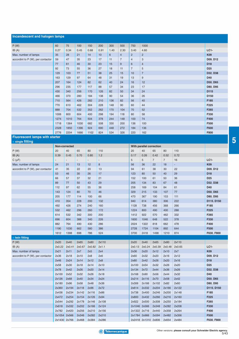
Other versions: please consult your Schneider Electric agency.5/43
5
Incandescent and halogen lamps
P (W) 60 75 100 150 200 300 500 750 1000
IB (A) 0.27 0.34 0.45 0.68 0.91 1.40 2.30 3.40 4.60 LC1-
Max. number of lamps 35 28 21 14 10 6 4 2 2 K09
accordint to P (W), per contactor 59 47 35 23 17 11 7 4 3 D09, D12
77 61 46 30 23 15 9 6 4 D18
92 73 55 36 27 18 11 7 5 D25
129 103 77 51 38 25 15 10 7 D32, D38
163 129 97 64 48 31 19 13 9 D40
207 164 124 82 62 40 24 16 12 D50, D65
296 235 177 117 88 57 34 23 17 D80, D95
430 340 256 170 126 82 50 34 24 D115
466 370 280 184 138 90 54 36 26 D150
710 564 426 282 210 136 82 56 40 F185
770 610 462 304 228 148 90 60 44 F225
888 704 532 352 262 170 104 70 52 F265
1006 800 604 400 298 194 118 80 58 F330
1274 1010 764 504 378 244 148 100 74 F400
1718 1364 1030 682 508 330 200 136 100 F500
2328 1850 1396 924 690 448 272 184 136 F600
2776 2204 1666 1102 824 534 326 220 162 F800
Fluorescent lamps with starter■ single fitting
Non-corrected With parallel correction
P (W) 20 40 65 80 110 20 40 65 80 110
IB (A) 0.39 0.45 0.70 0.80 1.2 0.17 0.26 0.42 0.52 0.72
C (µF) - - - - - 5 5 7 7 16 LC1-
Max. number of lamps 24 21 13 12 8 56 36 22 18 - K09
accordint to P (W), per contactor 41 35 22 20 13 94 61 38 30 22 D09, D12
53 46 30 26 17 123 80 50 40 29 D18
66 57 37 32 21 152 100 61 50 36 D25
89 77 50 43 29 205 134 83 67 48 D32, D38
112 97 62 55 36 258 169 104 84 61 D40
143 124 80 70 46 329 215 133 107 77 D50, D65
205 177 114 100 66 470 367 190 153 111 D80, D95
410 354 228 200 132 940 614 380 306 222 D115, D150
492 426 274 240 160 1128 738 456 368 266 F185
532 462 296 260 172 1224 800 490 400 288 F225
614 532 342 300 200 1412 922 570 462 332 F265
696 604 388 340 226 1600 1046 648 522 378 F330
882 764 490 430 286 2024 1322 818 662 478 F400
1190 1030 662 580 386 2728 1724 1104 892 644 F500
1612 1398 698 786 524 3700 2418 1498 1210 874 F630, F800
■ twin fitting
P (W) 2x20 2x40 2x65 2x80 2x110 2x20 2x40 2x65 2x80 2x110
IB (A) 2x0.22 2x0.41 2x0.67 2x0.82 2x1.1 2x0.13 2x0.24 2x0.39 2x0.48 2x0.65 LC1-
Max. number of lamps 2x21 2x11 2x7 2x5 2x4 2x36 2x20 2x12 2x10 2x7 K09
accordint to P (W), per contactor 2x36 2x18 2x10 2x8 2x6 2x60 2x32 2x20 2x16 2x12 D09, D12
2x46 2x24 2x14 2x12 2x8 2x80 2x42 2x26 2x20 2x16 D18
2x58 2x30 2x18 2x14 2x10 2x100 2x54 2x32 2x26 2x20 D25
2x78 2x42 2x26 2x20 2x14 2x134 2x72 2x44 2x36 2x26 D32, D38
2x100 2x52 2x32 2x26 2x18 2x168 2x90 2x56 2x44 2x32 D40
2x126 2x68 2x40 2x34 2x24 2x214 2x116 2x70 2x58 2x42 D50, D65
2x180 2x96 2x58 2x48 2x36 2x306 2x166 2x10² 2x82 2x60 D80, D95
2x360 2x194 2x118 2x96 2x72 2x614 2x332 2x204 2x166 2x122 D115, D150
2x436 2x234 2x142 2x116 2x86 2x738 2x400 2x246 2x200 2x148 F185
2x472 2x254 2x154 2x126 2x94 2x800 2x432 2x266 2x216 2x160 F225
2x544 2x292 2x178 2x146 2x10⁸ 2x922 2x500 2x308 2x250 2x184 F265
2x618 2x332 2x202 2x166 2x124 2x1046 2x566 2x348 2x282 2x208 F330
2x782 2x420 2x256 2x210 2x156 2x1322 2x716 2x440 2x358 2x264 F400
2x1054 2x566 2x346 2x282 2x210 2x1784 2x966 2x594 2x482 2x356 F500
2x1430 2x766 2x468 2x384 2x286 2x2418 2x1310 2x806 2x654 2x484 F630, F800
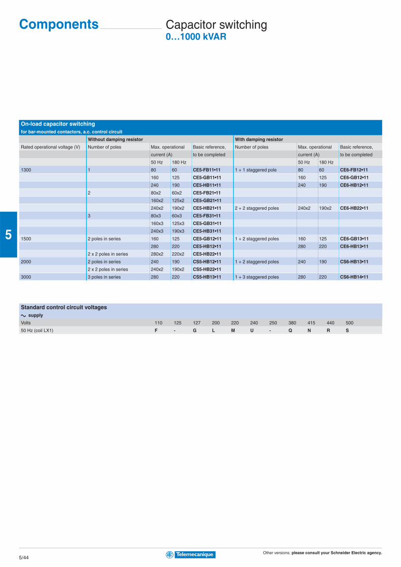
Other versions: please consult your Schneider Electric agency.5/44
5
On-load capacitor switchingfor bar-mounted contactors, a.c. control circuit
Without damping resistor With damping resistor
Rated operational voltage (V) Number of poles Max. operational Basic reference, Number of poles Max. operational Basic reference,
current (A) to be completed current (A) to be completed
50 Hz 180 Hz 50 Hz 180 Hz
1300 1 80 60 CE5-FB11•11 1 + 1 staggered pole 80 60 CE6-FB12•11
160 125 CE5-GB11•11 160 125 CE6-GB12•11
240 190 CE5-HB11•11 240 190 CE6-HB12•11
2 80x2 60x2 CE5-FB21•11
160x2 125x2 CE5-GB21•11
240x2 190x2 CE5-HB21•11 2 + 2 staggered poles 240x2 190x2 CE6-HB22•11
3 80x3 60x3 CE5-FB31•11
160x3 125x3 CE5-GB31•11
240x3 190x3 CE5-HB31•11
1500 2 poles in series 160 125 CE5-GB12•11 1 + 2 staggered poles 160 125 CE6-GB13•11
280 220 CE5-HB12•11 280 220 CE6-HB13•11
2 x 2 poles in series 280x2 220x2 CE5-HB22•11
2000 2 poles in series 240 190 CS5-HB12•11 1 + 2 staggered poles 240 190 CS6-HB13•11
2 x 2 poles in series 240x2 190x2 CS5-HB22•11
3000 3 poles in series 280 220 CS5-HB13•11 1 + 3 staggered poles 280 220 CS6-HB14•11
Components Capacitor switching0…1000 kVAR
Standard control circuit voltagesaaaaa supply
Volts 110 125 127 200 220 240 250 380 415 440 500
50 Hz (coil LX1) F - G L M U - Q N R S

Other versions: please consult your Schneider Electric agency.5/45
5
Maximum operational power of contactors■ standard contactors
Operational power at 50/60 Hz
θ ≥ 40 °C θ ≥ 55 °C Peak current Contactor
220 V 400 V 600 V 220 V 400 V 600 V size
240 V 440 V 690 V 240 V 440 V 690 V
kVAR kVAR kVAR kVAR kVAR kVAR A
6 11 15 6 11 15 560 LC1-D09, D12
9 15 20 9 15 20 850 LC1-D18
11 20 25 11 20 25 1600 LC1-D25
14 25 30 14 25 30 1900 LC1-D32, D38
17 30 37 17 30 37 2160 LC1-D40
22 40 50 22 40 50 2160 LC1-D50
22 40 50 22 40 50 3040 LC1-D65
35 60 75 35 60 75 3040 LC1-D80, D95
50 90 125 38 75 80 3100 LC1-D115
60 110 135 40 85 90 3300 LC1-D150
70 125 160 50 100 100 3500 LC1-F185
80 140 190 60 110 110 4000 LC1-F225
90 160 225 75 125 125 5000 LC1-F265
100 190 275 85 140 165 6500 LC1-F330
125 220 300 100 160 200 8000 LC1-F400
180 300 400 125 220 300 10000 LC1-F500
250 400 600 190 350 500 12000 LC1-F630
250 400 600 190 350 500 14200 LC1-F800
200 350 500 180 350 500 25000 LC1-BL
300 550 650 250 500 600 25000 LC1-BM
500 8350 950 400 750 750 25000 LC1-BP
600 1100 1300 500 1000 1000 25000 LC1-BR
■ special contactors
Operational power at 50/60 Hz
θ ≥ 55 °C Instantaneous auxiliary contacts Tightening torque on cable end Basic reference,
220 V 400 V 660 V to be completed
240 V 440 V 690 V
kVAR kVAR kVAR N/O N/C N.m
6.7 12.5 18 1 1 1.2 LC1-DFK11••
- 2 1.2 LC1-DFK02••
8.5 16.7 24 1 1 1.7 LC1-DGK11••
- 2 1.7 LC1-DGK02••
10 20 30 1 1 1.9 LC1-DLK11••
- 2 1.9 LC1-DLK02••
15 25 36 1 1 2.5 LC1-DMK11••
- 2 2.5 LC1-DMK02••
20 33.3 48 1 2 5 LC1-DPK12••
25 40 58 1 2 5 LC1-DTK12••
40 60 92 1 2 9 LC1-DWK12••
Standard control circuit voltagesaaaaa supply
Volts 24 42 48 110 115 220 230 240 380 400 415 440
50/60 Hz (coil LX1) B7 D7 E7 F7 FE7 M7 P7 U7 Q7 V7 N7 R7
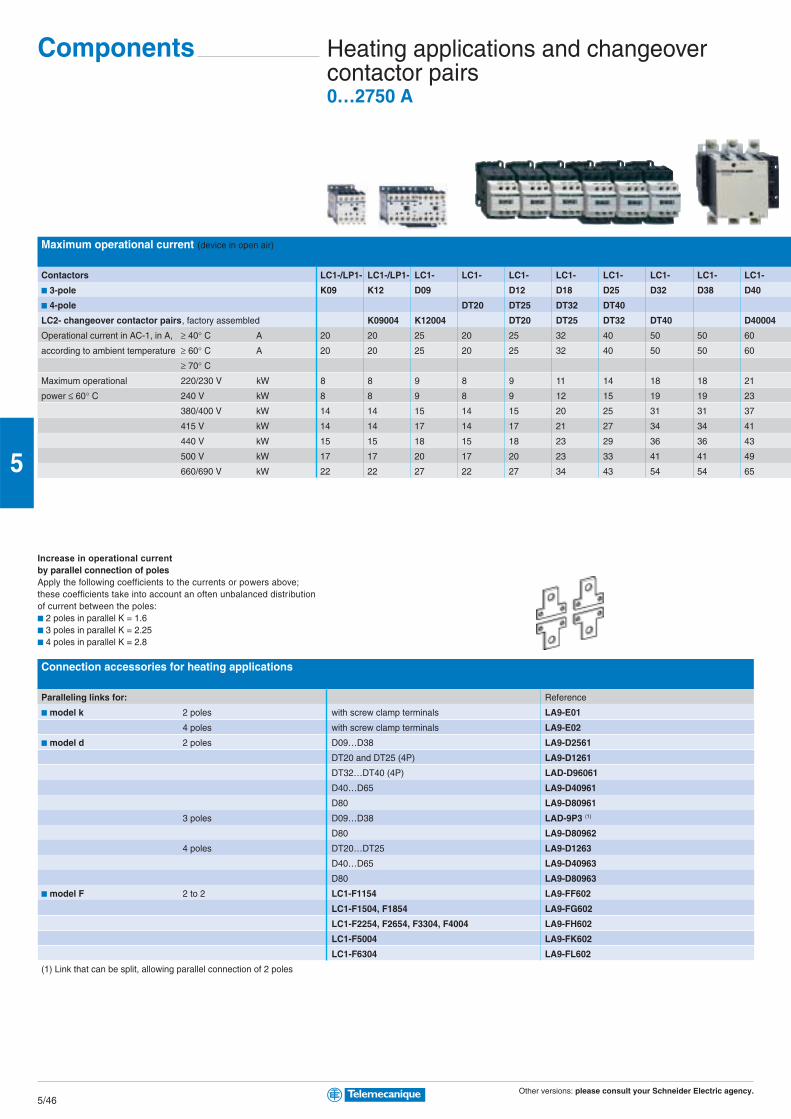
Other versions: please consult your Schneider Electric agency.5/46
5
Maximum operational current (device in open air)
Contactors LC1-/LP1- LC1-/LP1- LC1- LC1- LC1- LC1- LC1- LC1- LC1- LC1-
■ 3-pole K09 K12 D09 D12 D18 D25 D32 D38 D40
■ 4-pole DT20 DT25 DT32 DT40
LC2- changeover contactor pairs, factory assembled K09004 K12004 DT20 DT25 DT32 DT40 D40004
Operational current in AC-1, in A, ≥ 40° C A 20 20 25 20 25 32 40 50 50 60
according to ambient temperature ≥ 60° C A 20 20 25 20 25 32 40 50 50 60
≥ 70° CMaximum operational 220/230 V kW 8 8 9 8 9 11 14 18 18 21
power ≤ 60° C 240 V kW 8 8 9 8 9 12 15 19 19 23
380/400 V kW 14 14 15 14 15 20 25 31 31 37
415 V kW 14 14 17 14 17 21 27 34 34 41
440 V kW 15 15 18 15 18 23 29 36 36 43
500 V kW 17 17 20 17 20 23 33 41 41 49
660/690 V kW 22 22 27 22 27 34 43 54 54 65
Increase in operational current
by parallel connection of polesApply the following coefficients to the currents or powers above;these coefficients take into account an often unbalanced distributionof current between the poles:■ 2 poles in parallel K = 1.6■ 3 poles in parallel K = 2.25■ 4 poles in parallel K = 2.8
Connection accessories for heating applications
Paralleling links for: Reference
■ model k 2 poles with screw clamp terminals LA9-E01
4 poles with screw clamp terminals LA9-E02
■ model d 2 poles D09…D38 LA9-D2561
DT20 and DT25 (4P) LA9-D1261
DT32…DT40 (4P) LAD-D96061
D40…D65 LA9-D40961
D80 LA9-D80961
3 poles D09…D38 LAD-9P3 (1)
D80 LA9-D80962
4 poles DT20…DT25 LA9-D1263
D40…D65 LA9-D40963
D80 LA9-D80963
■ model F 2 to 2 LC1-F1154 LA9-FF602
LC1-F1504, F1854 LA9-FG602
LC1-F2254, F2654, F3304, F4004 LA9-FH602
LC1-F5004 LA9-FK602
LC1-F6304 LA9-FL602
(1) Link that can be split, allowing parallel connection of 2 poles
Heating applications and changeovercontactor pairs0…2750 A
Components
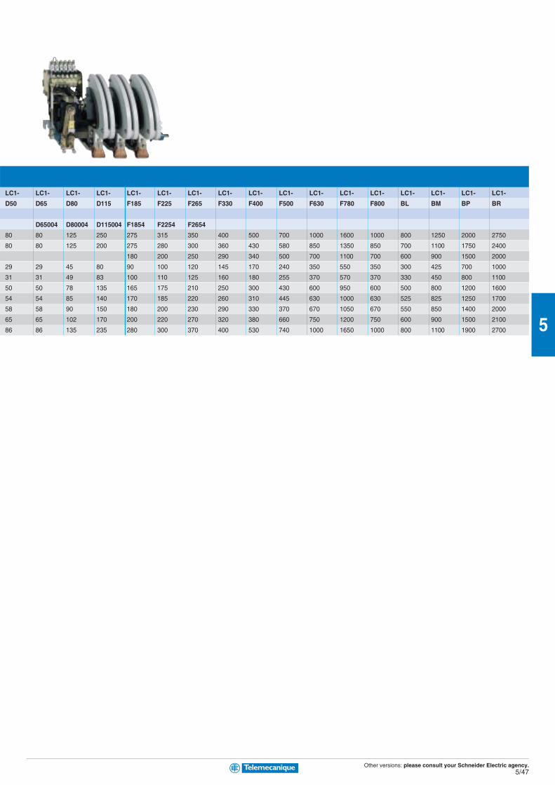
Other versions: please consult your Schneider Electric agency.5/47
5
LC1- LC1- LC1- LC1- LC1- LC1- LC1- LC1- LC1- LC1- LC1- LC1- LC1- LC1- LC1- LC1- LC1-
D50 D65 D80 D115 F185 F225 F265 F330 F400 F500 F630 F780 F800 BL BM BP BR
D65004 D80004 D115004 F1854 F2254 F2654
80 80 125 250 275 315 350 400 500 700 1000 1600 1000 800 1250 2000 2750
80 80 125 200 275 280 300 360 430 580 850 1350 850 700 1100 1750 2400
180 200 250 290 340 500 700 1100 700 600 900 1500 2000
29 29 45 80 90 100 120 145 170 240 350 550 350 300 425 700 1000
31 31 49 83 100 110 125 160 180 255 370 570 370 330 450 800 1100
50 50 78 135 165 175 210 250 300 430 600 950 600 500 800 1200 1600
54 54 85 140 170 185 220 260 310 445 630 1000 630 525 825 1250 1700
58 58 90 150 180 200 230 290 330 370 670 1050 670 550 850 1400 2000
65 65 102 170 200 220 270 320 380 660 750 1200 750 600 900 1500 2100
86 86 135 235 280 300 370 400 530 740 1000 1650 1000 800 1100 1900 2700
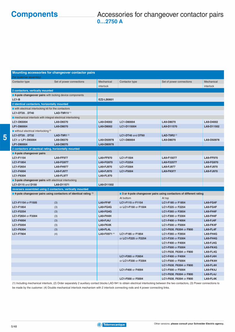
Other versions: please consult your Schneider Electric agency.5/48
5
Mounting accessories for changeover contactor pairs(for customer assembly)
Contactor type Set of power connections Mechanical Contactor type Set of power connections Mechanical
interlock interlock
2 contactors, vertically mounted
■ 4-pole changeover pairs with locking device components
LC1-B EZ2-LB0601
2 identical contactors, horizontally mounted
■ with electrical interlocking kit for the contactors
LC1-DT20…DT40 LAD-T9R1V (1)
■ mechanical interlock with integral electrical interlocking
LC1-D65004 LA9-D6570 LA9-D4002 LC1-D80004 LA9-D8070 LA9-D4002
LP1-D80004 LA9-D8070 LA9-D8002 LC1-D115004 LA9-D11570 LA9-D11502
■ without electrical interlocking (2)
LC1-DT20…DT32 LAD-T9R1 (2) LC1-DT40 and DT60 LAD-T9R2 (2)
LC1 or LP1-D65004 LA9-D6570 LA9-D50978 LC1-D80004 LA9-D8070 LA9-D50978
LP1-D80004 LA9-D8070 LA9-D80978
2 contactors of identical rating, horizontally mounted
■ 4-pole changeover pairs
LC1-F1154 LA9-FF977 LA9-FF970 LC1-F1504 LA9-F15077 LA9-FF970
LC1-F1854 LA9-FG977 LA9-FG970 LC1-F2254 LA9-F22577 LA9-FG970
LC1-F2654 LA9-FH977 LA9-FJ970 LC1-F3304 LA9-FJ977 LA9-FJ970
LC1-F4004 LA9-FJ977 LA9-FJ970 LC1-F5004 LA9-FK977 LA9-FJ970
LC1-F6304 LA9-FL977 LA9-FL970
■ 3-pole changeover pairs with electrical interlocking
LC1-D115 and D150 LA9-D11571 LA9-D11502
reversers assembled using 2 contactors, vertically mounted
■ 4-pole changeover pairs using contactors of identical rating (3) ■ 3 or 4-pole changeover pairs using contactors of different rating
At bottom At top
LC1-F1154 or F1505 (3) LA9-FF4F LC1-F115 or F1154 LC1-F185 or F1854 LA9-FG4F
LC1-F1854 (3) LA9-FG4G or LC1-F150 or F1504 LC1-F225 or F2254 LA9-FG4F
LC1-F2254 (3) LA9-FG4G LC1-F265 or F2654 LA9-FH4F
LC1-F2654 or F3304 (3) LA9-FH4H LC1-F300 or F3304 LA9-FH4F
LC1-F4004 (3) LA9-FJ4J LC1-F400 or F4004 LA9-FJ4F
LC1-F5004 (3) LA9-FK4K LC1-F500 or F5004 LA9-FK4F
LC1-F6304 (3) LA9-FL4L LC1-F630, F6304 or F800 LA9-FL4F
LC1-F7804 (4) LA9-FX971 (4) LC1-F185 or F1854 LC1-F265 or F2654 LA9-FH4G
or LC1-F225 or F2254 LC1-F330 or F3304 LA9-FH4G
LC1-F400 or F4004 LA9-FJ4G
LC1-F500 or F5004 LA9-FK4G
LC1-F630, F6304 or F800 LA9-FL4G
LC1-F265 or F2654 LC1-F400 or F4004 LA9-FJ4H
or LC1-F330 or F3304 LC1-F500 or F5004 LA9-FK4H
LC1-F630, F6304 or F800 LA9-FL4H
LC1-F400 or F4004 LC1-F500 or F5004 LA9-FK4J
LC1-F630, F6304 or F800 LA9-FL4J
LC1-F500 or F5004 LC1-F630, F6304 or F800 LA9-FL4K
(1) Including mechanical interlock, (2) Order separately 2 auxiliary contact blocks LAD-N•1 to obtain electrical interlocking between the two contactors, (3) Power connections to
be made by the customer. (4) Double mechanical interlock mechanism with 2 interlock connecting rods and 4 power connecting links.
Accessories for changeover contactor pairs0…2750 A
Components
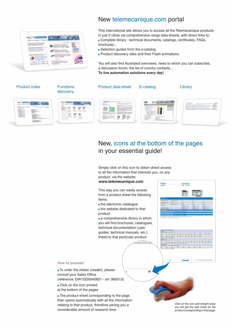
Other versions: please consult your Schneider Electric agency.2
Connections■ screw clamp terminals
Rated operational current Ie max AC-3 (Ue ≤ 440V) 6 A 9 A 12 A
Ie AC-1 (θ ≤ 40° C) - 20 A -
Rated operational power 220/240 V 1.5 kW 2.2 kW 3 kW
in category AC3 380/400 V…415/440 V 2.2 kW 4 kW 5.5 kW
660/690 V…500 V 3 kW 4 kW 4 kW
Contactor type (1)* c LC1-K06•• LC1-K09•• LC1-K12••
a LP1-K06•• or LP4-K06•• LP1-K09 or LP4-K09•• LP1-K12 or LP4-K12••
Reversing contactor type * c LC2-K06 LC2-K09 LC2-K12
with mechanical interlock a LP2-K06 or LP5-K06 LP2-K09 or LP5-K09 LP2-K12 or LP5-K12
■ spring terminals
Add the figure 3 before the voltage code. Example LC1-K0610•• becomes LC1-K06103••
■ Faston connectors, 1 x 6.35 or 2 x 2.8
Add the figure 7 before the voltage code. Example LC1-K0610•• becomes LC1-K06107••
■ solder pins for printed circuit boards
Add the figure 5 before the voltage code. Example LC1-K0610•• becomes LC1-K06105••
(1) Basic reference, to be completed by adding 01 for N/C auxiliary contact, or 10 for N/O auxiliary contact.
* Basic reference to be completed by adding the coil voltage
Standard control circuit voltagesc c c c c supply
Contactors LC1-K (0.8…1.15 Uc) (0.85…1.1UC)
Volts 12 20 24 36 42 48 110 115 120 127 200/208 220/230 230 230/240
50/60 Hz J7 Z7 B7 C7 D7 E7 F7 FE7 G7 FC7 L7 M7 P7 U7
Volts 256 277 380/400 400 400/415 440 480 500 575 600 660/690
50/60 Hz W7 UE7 Q7 V7 N7 R7 T7 S7 SC7 X7 Y7
Example of complete reference LC1-K0910P7
a a a a a supply
Contactors LP1-K (0.8…1.15 Uc)
Volts 12 20 24 36 48 60 72 100 110 125 155 174 200 220 230 240 250
Code JD ZD BD CD ED ND SD KD FD GD PD QD LD MD MPD MUD UD
Coil with integral suppression device available, add 3 to the code required. Example JD3
Low consumption
Contactors LP4-K (0.7…1.30 Uc), coil suppression as standard
Volts 12 20 24 48 72 110 120
Code JW3 ZW3 BW3 EW3 SW3 FW3 GW3
Example of complete reference LC1-K0910BD
TeSysmodel k
Contactors0.06…5.5 kW
2
Code JW3 ZW3
Example of complete reference LC1-K0910BD
Click on the icon and straight awayyou will get the web sheet for theproduct corresponding to that page.
New, icons at the bottom of the pagesin your essential guide!
Simply click on this icon to obtain direct accessto all the information that interests you, on anyproduct, via the website:www.telemecanique.com
This way you can easily accessfrom a product sheet the followingitems:b the electronic catalogueb the website dedicated to thatproductb a comprehensive library in whichyou will find brochures, catalogues,technical documentation (userguides, technical manuals, etc.)linked to that particular product.
New telemecanique.com portal
This international site allows you to access all the Telemecanique productsin just 2 clicks via comprehensive range data-sheets, with direct links to:b Complete library : technical documents, catalogs, certificates, FAQs,brochures...b Selection guides from the e-catalogb Product discovery sites and their Flash animations
You will also find illustrated overviews, news to which you can subscribe,a discussion forum, the list of country contacts...To live automation solutions every day!
Product index Functions Product data-sheet E-catalog Librarydiscovery
How to proceed
b To order the clicker (reader), pleaseconsult your Sales Office(reference: DIA1GD0040601 - art: 960013)
b Click on the icon printedat the bottom of the pages
b The product sheet corresponding to the pagethen opens automatically with all the informationrelating to that product, therefore saving you aconsiderable amount of research time.
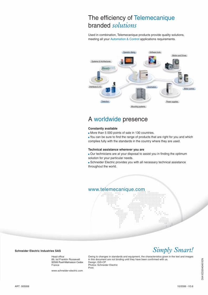
Systems & Architectures
Software toolsMotion and Drives
Power supplies
Mounting systems
Interfaces & I/O
Operator dialog
Detection
AutomationMotor control
DIA
1ED
2040
401E
N
ART. 005006 10/2006 - V3.6
The efficiency of Telemecaniquebranded solutionsUsed in combination, Telemecanique products provide quality solutions,meeting all your Automation & Control applications requirements.
A worldwide presenceConstantly availableb More than 5 000 points of sale in 130 countries.b You can be sure to find the range of products that are right for you and whichcomplies fully with the standards in the country where they are used.
Technical assistance wherever you areb Our technicians are at your disposal to assist you in finding the optimumsolution for your particular needs.b Schneider Electric provides you with all necessary technical assistancethroughout the world.
Schneider Electric Industries SAS
Head office89, bd Franklin Roosevelt92506 Rueil-Malmaison CedexFrance
www.schneider-electric.com
Owing to changes in standards and equipment, the characteristics given in the text and imagesin this document are not binding until they have been confirmed with us.Design: IGS-CPPhotos: Schneider ElectricPrint:
Simply Smart!
www.telemecanique.com