Embed Size (px)
Citation preview
Motor Control of an Oscillating Pendulum
Nick Myers and Chirag PatelMarch 9, 2004
Advised by: Dr. James Irwin and Mr. Jose SanchezBradley University Department of Electrical Engineering
and Technology
Presentation Overview•Project Objectives
•System Block Diagrams
•Original Schedule of Tasks to be completed
•Work Completed (Nick)
•Work to be Completed (Nick)
•Work Completed (Chirag)
•Work to be Completed (Chirag)
•Revised Schedule of Tasks to be completed
•Summary of Progress
•Questions
Objectives
To initialize the oscillation of a weighted pendulum using microprocessor controlled motor bursts.
To oscillate the pendulum to a predefined angle and, using optical sensor outputs, maintain the angle of oscillation.
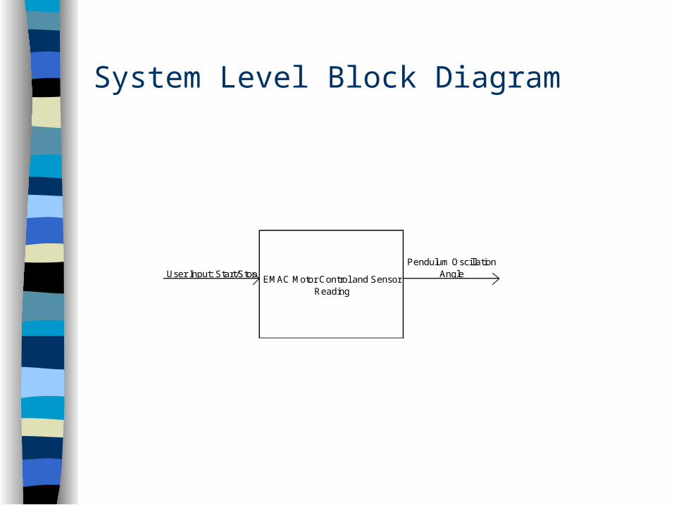
System Level Block Diagram
EMAC Motor Control and Sensor Reading
User Input: Start/StopPendulum Oscillation
Angle
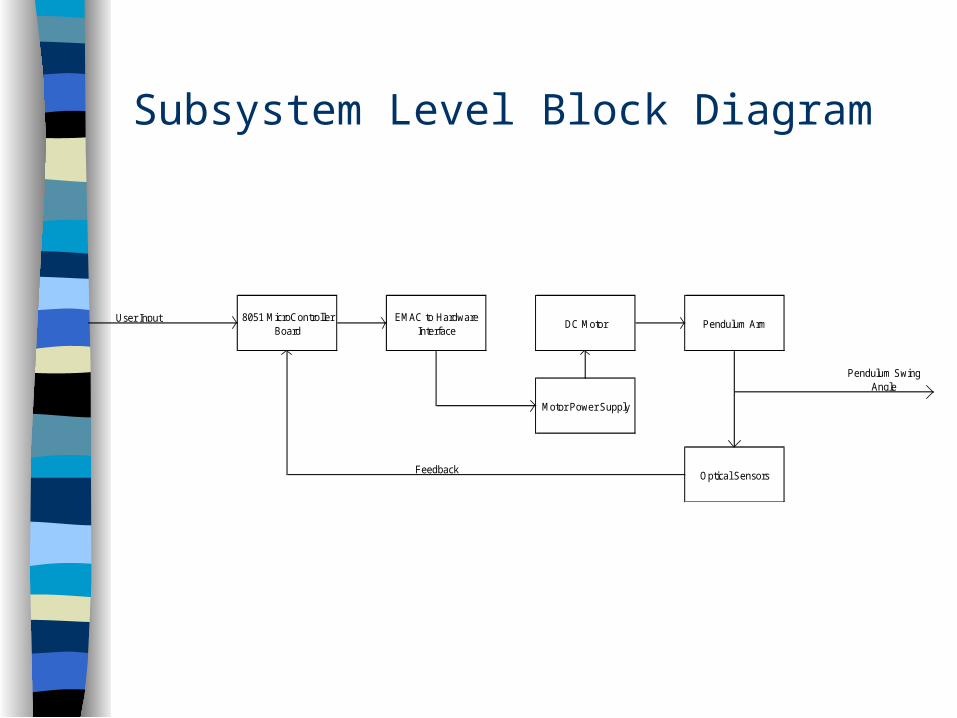
Subsystem Level Block Diagram
Pendulum Swing Angle
Pendulum Arm
Optical Sensors
8051 MicroController Board
EMAC to Hardware Interface
DC Motor
Motor Power Supply
User Input
Feedback
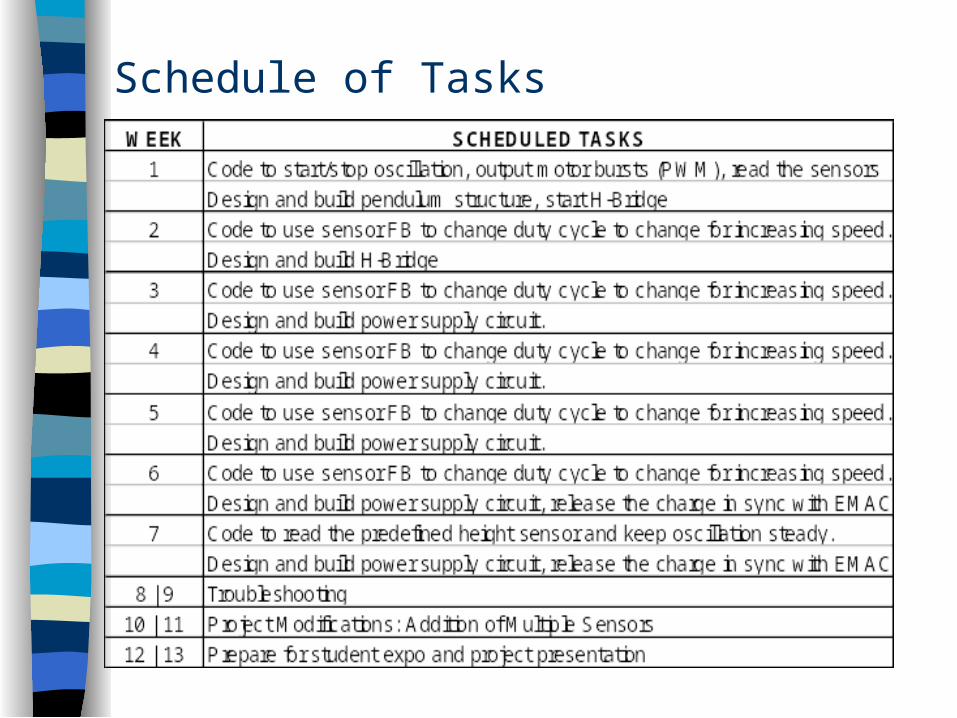
Schedule of Tasks
Goals Accomplished to Date
Motor control switch to allow user to switch motor on/off
H-bridge hardware to allow motor to turn in both directions
H-bridge microprocessor code to switch H-bridge automatically based on pendulum location and direction
Construction of our pendulum unit
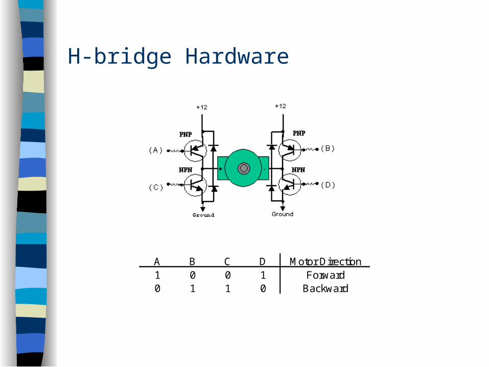
H-bridge Hardware
A B C D Motor Direction1 0 0 1 Forward0 1 1 0 Backward
H-bridge Hardware
The H-bridge uses (4) N-Channel Power Transistors
The H-bridge operates on a supply voltage of +15V DC
The H-bridge ideally accepts input voltages of 0V or +15V DC
Finding the appropriate transistors to power our motor was difficult
H-bridge Microprocessor Code
The H-bridge will switch motor burst direction every time the pendulum passes equilibrium.
Once the direction is switched, a burst will immediately be sent.
The H-bridge code will be called by the sensor input interrupt.
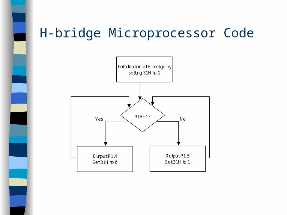
H-bridge Microprocessor Code
Yes No
Initialization of H-bridge by setting 31H to 1
Output P1.4Set 31H to 0
31H=1?
Output P1.5Set 31H to 1
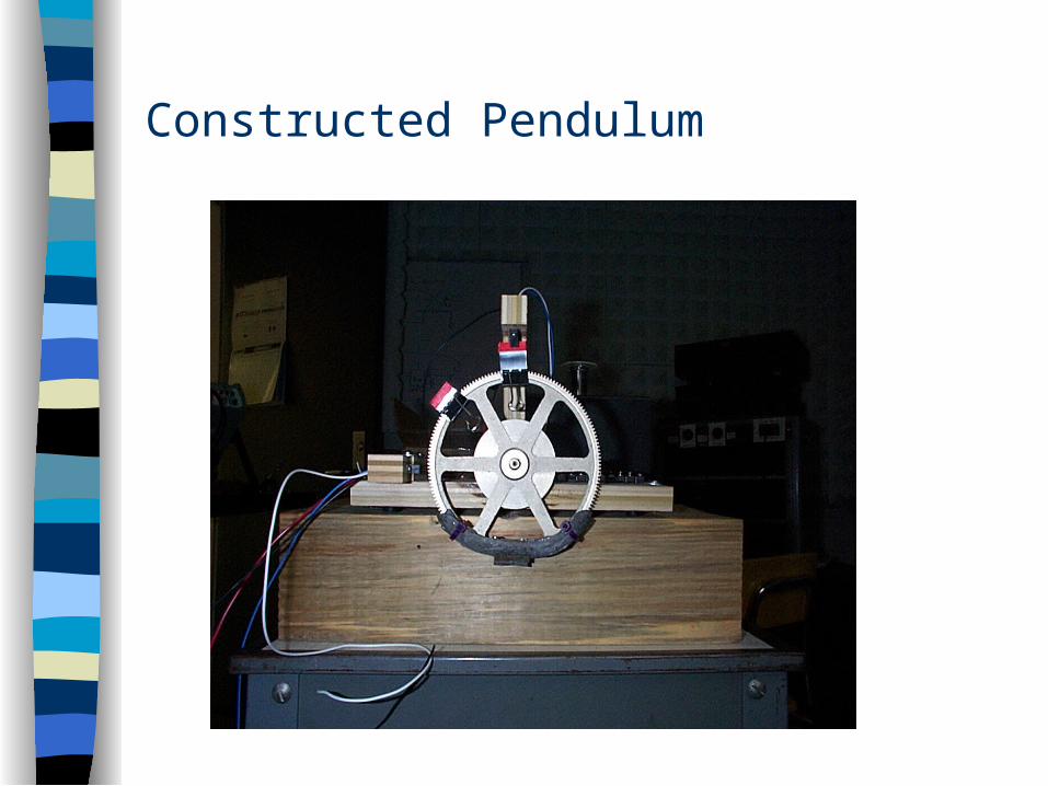
Constructed Pendulum

Goals to be Accomplished
Complete hardware interface for EMAC to H-bridge
Calculate timing for motor burst lengths to be called by H-bridge code
Create timing code that will burst the motor with increasing lengths as pendulum period increases
Compile H-bridge code with all other project codes
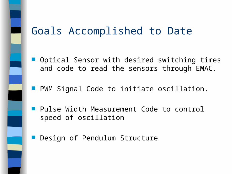
Goals Accomplished to Date
Optical Sensor with desired switching times and code to read the sensors through EMAC.
PWM Signal Code to initiate oscillation.
Pulse Width Measurement Code to control speed of oscillation
Design of Pendulum Structure
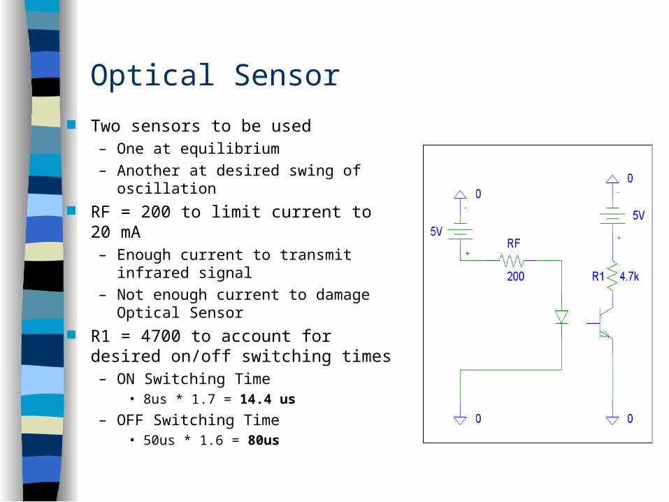
Optical Sensor
Two sensors to be used– One at equilibrium
– Another at desired swing of oscillation
RF = 200 to limit current to 20 mA– Enough current to transmit infrared
signal
– Not enough current to damage Optical Sensor
R1 = 4700 to account for desired on/off switching times– ON Switching Time
• 8us * 1.7 = 14.4 us
– OFF Switching Time• 50us * 1.6 = 80us

PWM Signal
Current PWM signal = 1khz @ 33% Duty cycle. – Actual frequency will be
much smaller. PWM signal will be used to
initiate the oscillation of the pendulum.– Once pendulum is beyond
the equilibrium sensor, timed pulse signals will be used to oscillate the pendulum.

Pulse Width Measurement
Pulse Width Measurement code used to measure length of time sensor is obstructed by pendulum.– This time will be used to
control the length of the pulse sent to motor to control oscillation of pendulum.
• Faster oscillation = Smaller pulses
• Slower oscillation = Larger pulses

Goals to be Accomplished
Construct code for the timed pulses of constant length in order to sustain oscillation beyond the equilibrium sensor.
Construct code to adjust the length of the timed pulses which will be dependent upon the pulse width measurement.
Construct code to maintain oscillation once the predefined height sensor is reached.
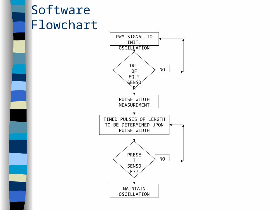
Software FlowchartPWM SIGNAL TO
INIT. OSCILLATION
PULSE WIDTH MEASUREMENT
TIMED PULSES OF LENGTH TO BE DETERMINED UPON
PULSE WIDTH
OUT OF
EQ.? SENSO
R
PRESET
SENSOR??
MAINTAIN OSCILLATION
NO
NO
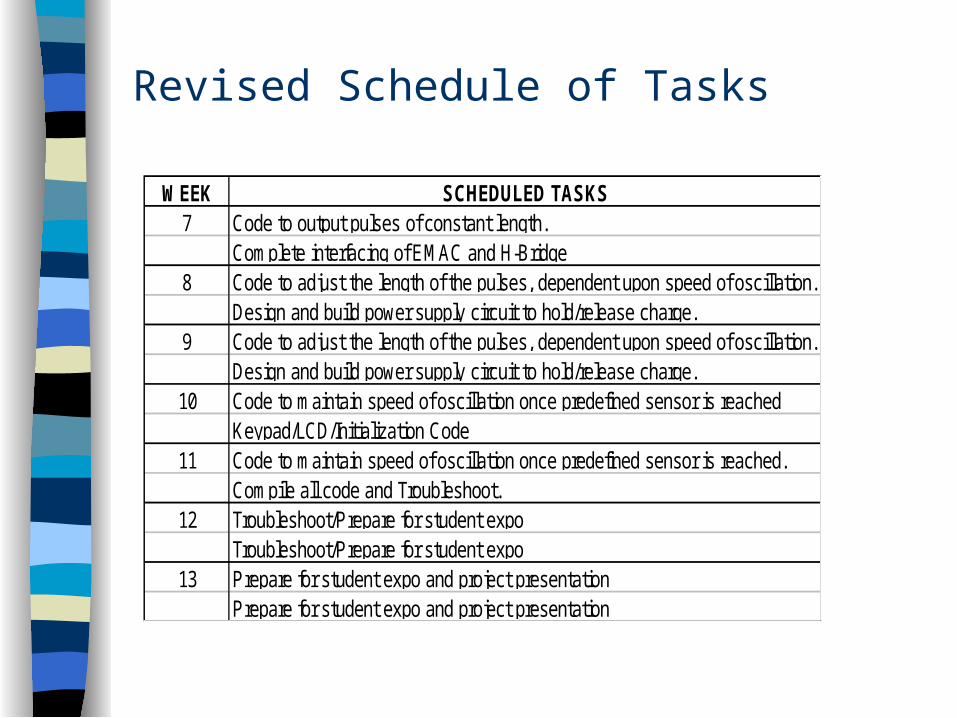
Revised Schedule of Tasks
WEEK SCHEDULED TASKS7
8
9
10
11
12
13
Code to output pulses of constant length.Complete interfacing of EMAC and H-Bridge
Design and build power supply circuit to hold/release charge.Code to adjust the length of the pulses, dependent upon speed of oscillation.
Code to adjust the length of the pulses, dependent upon speed of oscillation.
Design and build power supply circuit to hold/release charge.
Troubleshoot/Prepare for student expo
Prepare for student expo and project presentation
Code to maintain speed of oscillation once predefined sensor is reachedKeypad/LCD/Initialization Code
Prepare for student expo and project presentation
Code to maintain speed of oscillation once predefined sensor is reached.Compile all code and Troubleshoot.Troubleshoot/Prepare for student expo
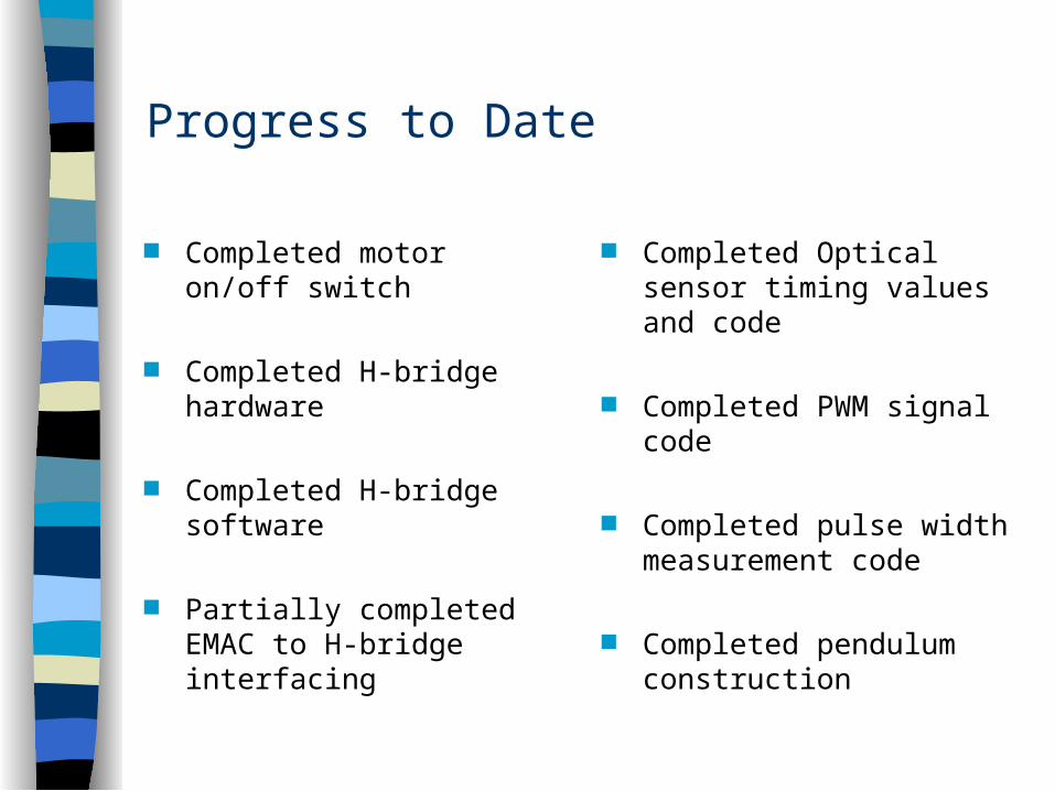
Progress to Date
Completed motor on/off switch
Completed H-bridge hardware
Completed H-bridge software
Partially completed EMAC to H-bridge interfacing
Completed Optical sensor timing values and code
Completed PWM signal code
Completed pulse width measurement code
Completed pendulum construction
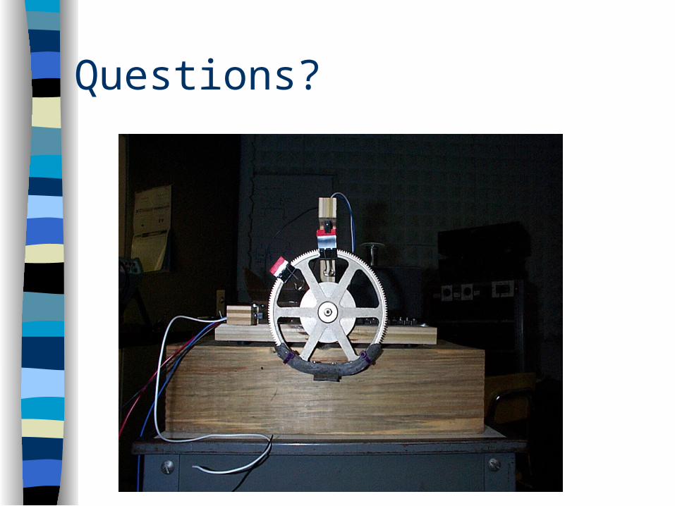
Questions?


![NIRMASHUDH [ pancholi chirag ]](https://img.pdfslide.us/doc/110x75/577ce7b51a28abf10395a048/nirmashudh-pancholi-chirag-.jpg)