Embed Size (px)
Citation preview

Page 1
Motor-CAD electromagnetic modelling using imported DXF Geometry
(January 2015)
1. Description In addition to its own standard geometries, Motor-CAD allows the user to model the
electromagnetic performance of the machine using imported geometry in the DXF format. This
tutorial demonstrates the importation and modelling process using an example of an automotive
traction motor. For more information on electromagnetic modelling, please refer to the “Motor-CAD
combined electromagnetic and thermal model” tutorial available at electromagnetic_model.pdf
2. Geometry Import Modelling Overview Electromagnetic modelling in Motor-CAD is achieved by transferring the model geometry to the
Finite Element electromagnetic solver. When using a DXF import, the standard geometry is replaced
with the imported geometry, however key dimensional data such as airgap size,lamination and
diameters are obtained from the Motor-CAD model. It is therefore necessary to set these properties
in the Motor-CAD model to match the imported geometry.
Motor-CAD electromagnetic modelling is performed by using machine symmetry (the default) or full
machine modes. Both types of geometry can be imported and modelled using the appropriate
modes.

Page 2
3. DXF Geometry Requirements In order to use imported DXF geometry, it must observe the following conditions:
1. The rotation axis must the centred on the origin (0, 0).
2. The stator and rotor laminations must be oriented so that the stator tooth and edge of rotor pole
region are aligned on the x axis.
3. The airgap region must be represented by concentric circles or arcs forming a smooth continuous
inner and outer surface. This requires that all slot openings be closed.
4. Each slot region needs to be divided into two regions in order that the current density can be
assigned correctly.
Shown below is the machine geometry which will be modelled in single slot/pole and full machine
versions. Note the position and alignment with reference to the DXF Geometry Requirements.

Page 3
4. Motor-CAD Model Preparation Launch Motor-CAD and set the model type to Magnetic.
5.
Set the key dimensional parameters:
1. Slot and Pole numbers to the required slot/pole combination
2. Outer and bore diameter of the stator lamination
3. Airgap thickness
Note: At this stage, approximate values may be used for the airgap dimensions if the exact values
are not known. Also it may be necessary to adjust the housing diameter (if applicable) to a suitable
value to display the geometry correctly.

Page 4
5. Importing the DXF Geometry From the Main Menu, select File > Geometry Import or press Ctrl + I.
Use the DXF Import dialog to select the desired DXF file. Ensure “Auto Centre” is unchecked and the
x and y offsets are at 0.
Page 5
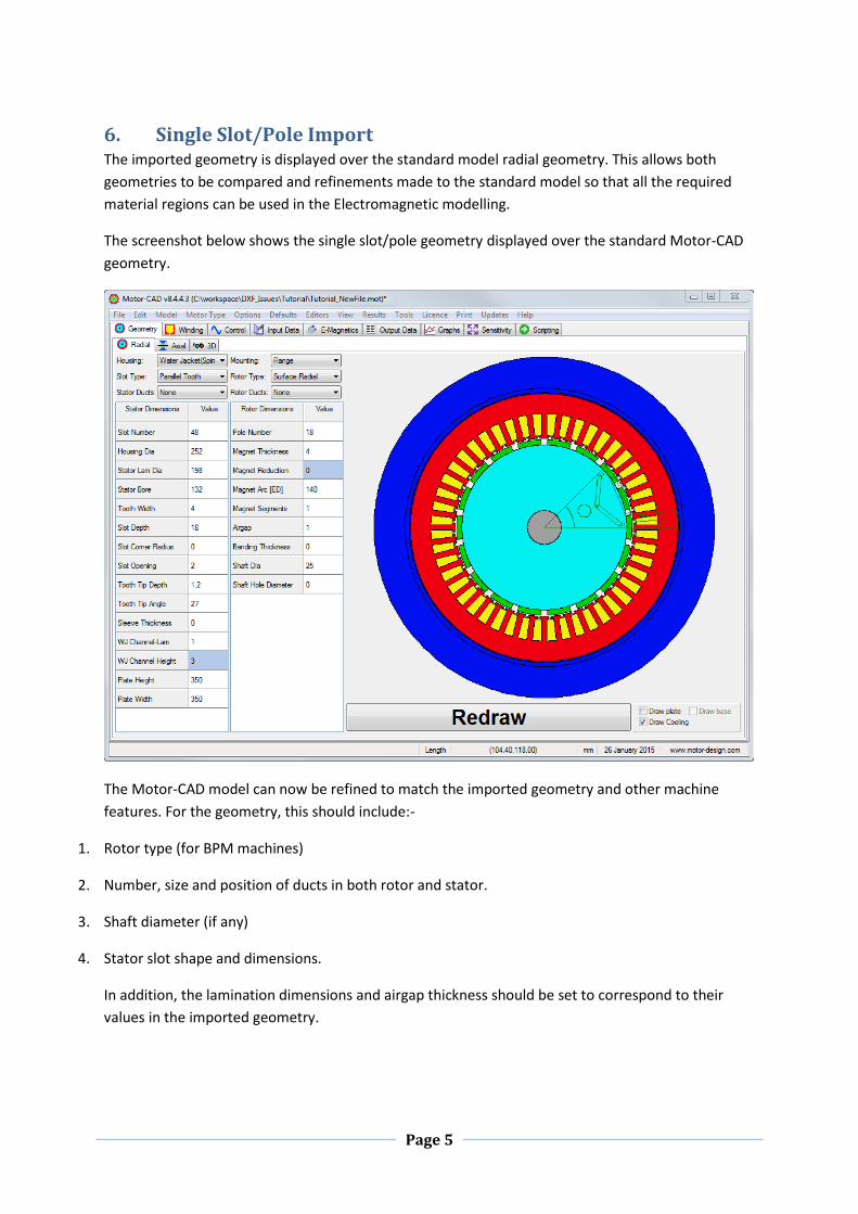
6. Single Slot/Pole Import The imported geometry is displayed over the standard model radial geometry. This allows both
geometries to be compared and refinements made to the standard model so that all the required
material regions can be used in the Electromagnetic modelling.
The screenshot below shows the single slot/pole geometry displayed over the standard Motor-CAD
geometry.
The Motor-CAD model can now be refined to match the imported geometry and other machine
features. For the geometry, this should include:-
1. Rotor type (for BPM machines)
2. Number, size and position of ducts in both rotor and stator.
3. Shaft diameter (if any)
4. Stator slot shape and dimensions.
In addition, the lamination dimensions and airgap thickness should be set to correspond to their
values in the imported geometry.

Page 6
7. Refining the Motor-CAD model
For this imported geometry, the magnet geometry can be approximated by selecting the Interior V
(web) type with 2 layers. Circular ducts can be selected for the rotor, and the dimensions for the slot
and shaft can be adjusted.
By performing this refinement, the regions from the Motor-CAD geometry will closely match the
required regions in the DXF geometry and will minimise the amount of region editing required.
Note: To assist in refining the Motor-CAD geometry, the geometry import dialog may be used to
rotate the DXF geometry by the required amount (usually the pole pitch: 22.5° in this example) so
that the imported and Motor-CAD poles line up over each other.

Page 7
8. FEA Region Editing The FEA Region editor allows regions to be moved, copied or deleted, while referring to the selected
geometry.
Select the E-Magnetics tab then the FEA Editor tab. The Motor-CAD FEA region editor display is
shown below:
The geometry and regions initially displayed are those from the Motor-CAD model. To switch to the
imported geometry, check the “Use DXF E-Magnetic” checkbox. The imported geometry is now
shown in the region editor, and will be used by the EM solver.

Page 8
All regions which have a complete boundary should be defined by placing a region identifier within
it. The regions are indicated by coloured rectangles, or in the case of permanent magnets, by an
arrow indicating the magnetisation direction. Clicking on a region selects it and highlights its entry in
the region table and vice versa.
The positions tab displays all regions with their coordinates. The E-Magnetics tab displays only
permanent magnet regions with magnetisation data.
To move a region, drag it with the left mouse button. The coordinates are updated as it is moved.
To zoom into an area, left click an area of the display (not on a FEA region) and drag to form a
rectangle to define the area to zoom into.
To restore the geometry view, double click the display.

Page 9
FEA regions can be copied and deleted using the region editing buttons.
To use these options, select a region by clicking the table entry or the symbol on the geometry
display. The options are as follows:-
1. Copy.
Creates one copy of the selected regions and places above and to the right of the original
2. Copy+
Clicking this options brings a up a window offering advanced copying options such as
number of copies and pitch of copies in a circular pattern:
3. Reset.
This will reset the custom FEA regions to the standard Motor-CAD regions
4. Delete.
This will remove the selected FEA region. Care should be used when doing this as it is not
possible to add regions which are not based on existing ones.
The Copy, Copy+ and Delete options are also available as a context menu by right-clicking the FEA
region.
When regions are edited, the “E-Magnetic” Custom Regions setting is automatically enabled. Custom
Region data is stored in the Motor-CAD .mot file.

Page
10
The geometry is now ready for passing to the EM Finite Element Solver. The other model details
including the control, winding, material and axial dimensions also need to be entered into the model
using the user interface.
Start the solver by clicking the “Solve E-Magnetic Model” button on the “FEA” or “Control” tab. The
solver uses the symmetry of the machine to quickly solve the model and produce results. The
geometry after solving is shown below:

Page
11
9. Full Machine Import The full machine import feature allows electromagnetic simulation on geometries which have non-
symmetrical features e.g. duct features which are non-multiples of the number of slots or poles.
Follow sections 3, 4, 5 and 6 described above to import the DXF geometry and refine the Motor-CAD
model. Then select the FEA region editor. When using full machine geometry, ensure the “Use DXF
as Entire Machine” option is checked (see below).
The display shows the full machine geometry with the standard Motor-CAD regions defined for one
slot and pole. What is now required is for all the remaining slots, poles and other areas to be defined
with copies from the defined regions.
Beginning with the rotor, it can be seen that the shaft and rotor lamination are single regions and
have already been defined. The magnets and ducts do need to be copied, which can be achieved as
follows.
Select one of the regions e.g. the circular duct between the magnets and the shaft. Click Copy+
above the region table or from the right click context menu.

Page
12
Select “Rotor Pitch” with the Copy Pitch drop down box. The pitch in degrees and the number of
copies will be automatically selected. Clicking OK will insert this pattern of copies into the FEA region
table and display them on the geometry viewer.
Repeat this step for the each of the RotorAir regions around the magnets which will also need
copying, the result of which can be seen below.

Page
13
The magnets and slot regions are specialised regions which need to be copied using a different
option. Right clicking one of the existing magnet regions will show an extended context menu.
Click “Complete Magnet Regions” to automatically assign the remaining magnet regions with the
correct region properties.
Moving on to the stator, the slot wedge and air regions need to be copied. For each of these, use the
Copy+ option with the Stator Pitch selected.

Page
14
Finally, right click on the slot winding regions.
Click “Complete Slot Regions” to assign slot winding regions to the remaining slots.

Page
15
The geometry is now ready for passing to the EM Finite Element Solver. Initiate the solver by clicking
“Solve E-Magnetic Model” on the “Control” tab or the “FEA” tab as shown below:

Page
16
The geometry after solving is shown below.
10. Conclusion This example shows how to use partial and full machine geometry imports can be used to calculate
the machine performance taking into account detailed geometric features in a design.


![;DdfggLo ;efd'v dxf]bo,¤¬जेट वक्तव्य... · ;DdfggLo ;efd'v dxf]bo, ... 20=](https://img.pdfslide.us/doc/110x75/6134e767dfd10f4dd73c0746/ddfgglo-efdv-dxfbo-aoeaa-aaaaaaa-ddfgglo-efdv-dxfbo.jpg)