Embed Size (px)
Citation preview
MotionProMidway Design Report
Elizabeth Cole - EE, Jinbang Fu - EE, Delphine Mweze - CSE, May Oo - EE
Abstract— Our team is designing and building a system thatprojects an electronic game onto any flat surface. The user willbe able to play the game while touching any surface withouttouching any sensors or buttons. We will be detecting the motionand location of the users hand using a camera and ultrasonicsensors. To project the game, we will be using a microcontrollerand a pico-projector to make the system as portable as possible.This is a step towards hologram gaming, which will allow fortrue player immersion.
I. INTRODUCTION
Interactive display technology has had a significantim0pact on our soci0.jmjnb v ety, and the future. Severalrevolutions of inventions have led to the advanced technologythat we are utilizing today. It all started with the ancientorigins of using clay tablets with a stylus in order tolearn in classroom or inscribe lessons. Later in the year of1801, blackboards were invented for the main purpose ofeducation. Due to their low cost, ease of use, effectiveness,and simplicity, they became essential for schools. In the1980s, whiteboards, or dry erase board were introduced [1].In 1991, interactive whiteboards which enhanced classroominteraction and learning were invented. The LCD projectorwhich is now connected to an interactive whiteboard projectscontent from a computer onto the surface of the board. Thecontent can be controlled by a pointer or touch of the handinstead of using a keyboard or mouse [2].
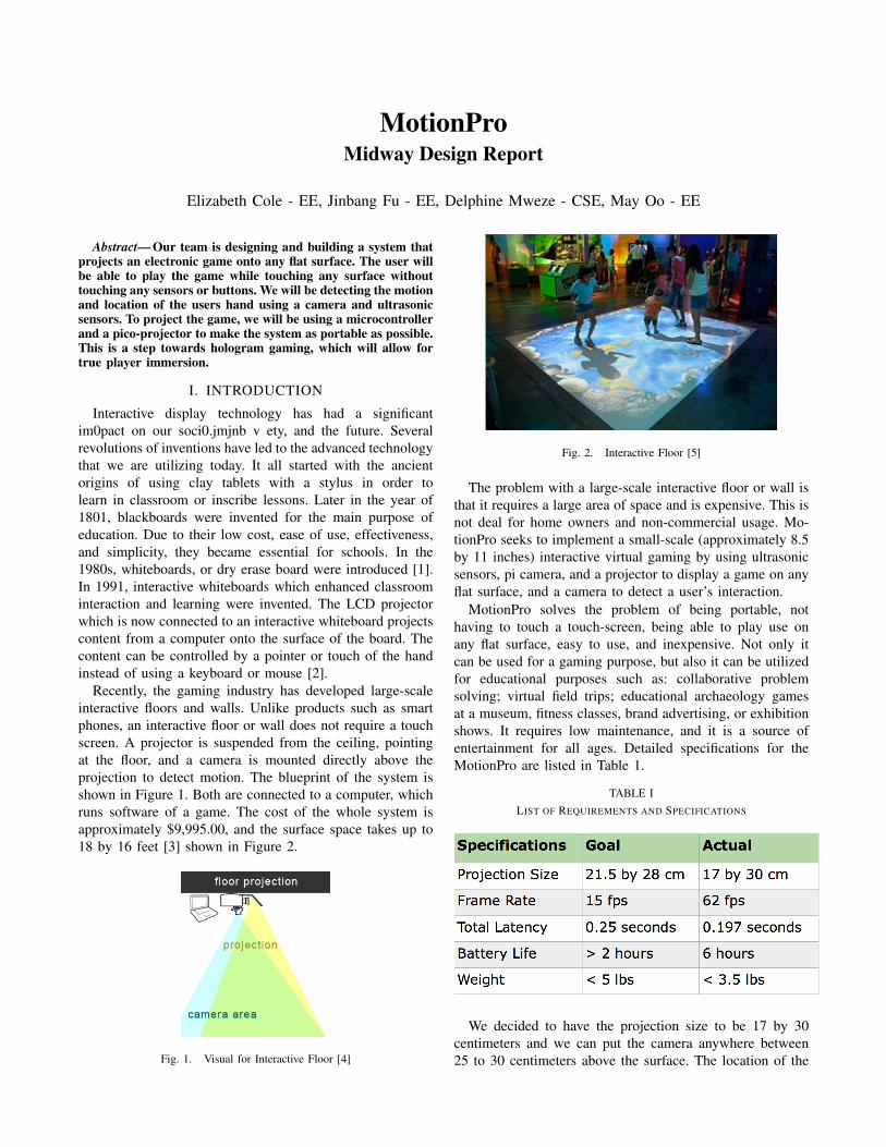
Recently, the gaming industry has developed large-scaleinteractive floors and walls. Unlike products such as smartphones, an interactive floor or wall does not require a touchscreen. A projector is suspended from the ceiling, pointingat the floor, and a camera is mounted directly above theprojection to detect motion. The blueprint of the system isshown in Figure 1. Both are connected to a computer, whichruns software of a game. The cost of the whole system isapproximately $9,995.00, and the surface space takes up to18 by 16 feet [3] shown in Figure 2.
Fig. 1. Visual for Interactive Floor [4]
Fig. 2. Interactive Floor [5]
The problem with a large-scale interactive floor or wall isthat it requires a large area of space and is expensive. This isnot deal for home owners and non-commercial usage. Mo-tionPro seeks to implement a small-scale (approximately 8.5by 11 inches) interactive virtual gaming by using ultrasonicsensors, pi camera, and a projector to display a game on anyflat surface, and a camera to detect a user’s interaction.
MotionPro solves the problem of being portable, nothaving to touch a touch-screen, being able to play use onany flat surface, easy to use, and inexpensive. Not only itcan be used for a gaming purpose, but also it can be utilizedfor educational purposes such as: collaborative problemsolving; virtual field trips; educational archaeology gamesat a museum, fitness classes, brand advertising, or exhibitionshows. It requires low maintenance, and it is a source ofentertainment for all ages. Detailed specifications for theMotionPro are listed in Table 1.
TABLE ILIST OF REQUIREMENTS AND SPECIFICATIONS
We decided to have the projection size to be 17 by 30centimeters and we can put the camera anywhere between25 to 30 centimeters above the surface. The location of the
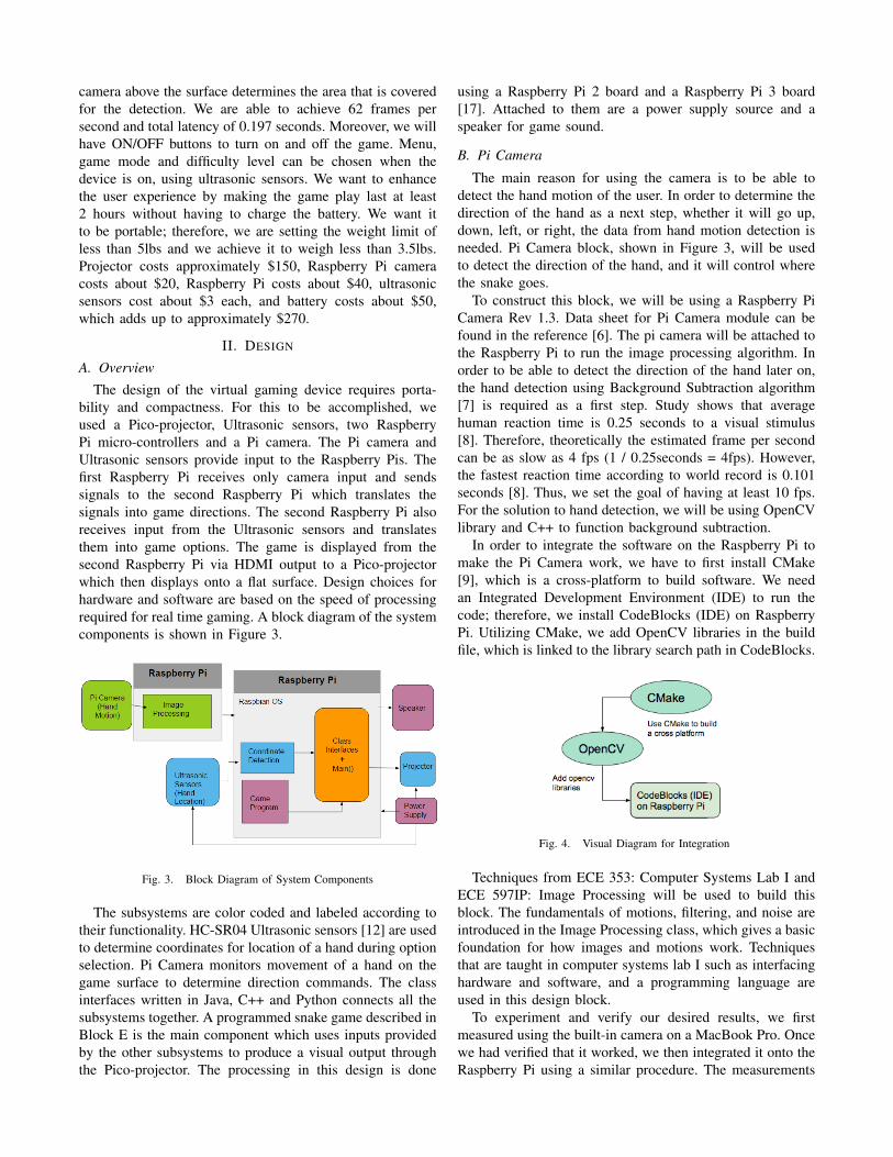
camera above the surface determines the area that is coveredfor the detection. We are able to achieve 62 frames persecond and total latency of 0.197 seconds. Moreover, we willhave ON/OFF buttons to turn on and off the game. Menu,game mode and difficulty level can be chosen when thedevice is on, using ultrasonic sensors. We want to enhancethe user experience by making the game play last at least2 hours without having to charge the battery. We want itto be portable; therefore, we are setting the weight limit ofless than 5lbs and we achieve it to weigh less than 3.5lbs.Projector costs approximately $150, Raspberry Pi cameracosts about $20, Raspberry Pi costs about $40, ultrasonicsensors cost about $3 each, and battery costs about $50,which adds up to approximately $270.
II. DESIGN
A. Overview
The design of the virtual gaming device requires porta-bility and compactness. For this to be accomplished, weused a Pico-projector, Ultrasonic sensors, two RaspberryPi micro-controllers and a Pi camera. The Pi camera andUltrasonic sensors provide input to the Raspberry Pis. Thefirst Raspberry Pi receives only camera input and sendssignals to the second Raspberry Pi which translates thesignals into game directions. The second Raspberry Pi alsoreceives input from the Ultrasonic sensors and translatesthem into game options. The game is displayed from thesecond Raspberry Pi via HDMI output to a Pico-projectorwhich then displays onto a flat surface. Design choices forhardware and software are based on the speed of processingrequired for real time gaming. A block diagram of the systemcomponents is shown in Figure 3.
Fig. 3. Block Diagram of System Components
The subsystems are color coded and labeled according totheir functionality. HC-SR04 Ultrasonic sensors [12] are usedto determine coordinates for location of a hand during optionselection. Pi Camera monitors movement of a hand on thegame surface to determine direction commands. The classinterfaces written in Java, C++ and Python connects all thesubsystems together. A programmed snake game described inBlock E is the main component which uses inputs providedby the other subsystems to produce a visual output throughthe Pico-projector. The processing in this design is done
using a Raspberry Pi 2 board and a Raspberry Pi 3 board[17]. Attached to them are a power supply source and aspeaker for game sound.
B. Pi Camera
The main reason for using the camera is to be able todetect the hand motion of the user. In order to determine thedirection of the hand as a next step, whether it will go up,down, left, or right, the data from hand motion detection isneeded. Pi Camera block, shown in Figure 3, will be usedto detect the direction of the hand, and it will control wherethe snake goes.
To construct this block, we will be using a Raspberry PiCamera Rev 1.3. Data sheet for Pi Camera module can befound in the reference [6]. The pi camera will be attached tothe Raspberry Pi to run the image processing algorithm. Inorder to be able to detect the direction of the hand later on,the hand detection using Background Subtraction algorithm[7] is required as a first step. Study shows that averagehuman reaction time is 0.25 seconds to a visual stimulus[8]. Therefore, theoretically the estimated frame per secondcan be as slow as 4 fps (1 / 0.25seconds = 4fps). However,the fastest reaction time according to world record is 0.101seconds [8]. Thus, we set the goal of having at least 10 fps.For the solution to hand detection, we will be using OpenCVlibrary and C++ to function background subtraction.
In order to integrate the software on the Raspberry Pi tomake the Pi Camera work, we have to first install CMake[9], which is a cross-platform to build software. We needan Integrated Development Environment (IDE) to run thecode; therefore, we install CodeBlocks (IDE) on RaspberryPi. Utilizing CMake, we add OpenCV libraries in the buildfile, which is linked to the library search path in CodeBlocks.
Fig. 4. Visual Diagram for Integration
Techniques from ECE 353: Computer Systems Lab I andECE 597IP: Image Processing will be used to build thisblock. The fundamentals of motions, filtering, and noise areintroduced in the Image Processing class, which gives a basicfoundation for how images and motions work. Techniquesthat are taught in computer systems lab I such as interfacinghardware and software, and a programming language areused in this design block.
To experiment and verify our desired results, we firstmeasured using the built-in camera on a MacBook Pro. Oncewe had verified that it worked, we then integrated it onto theRaspberry Pi using a similar procedure. The measurements
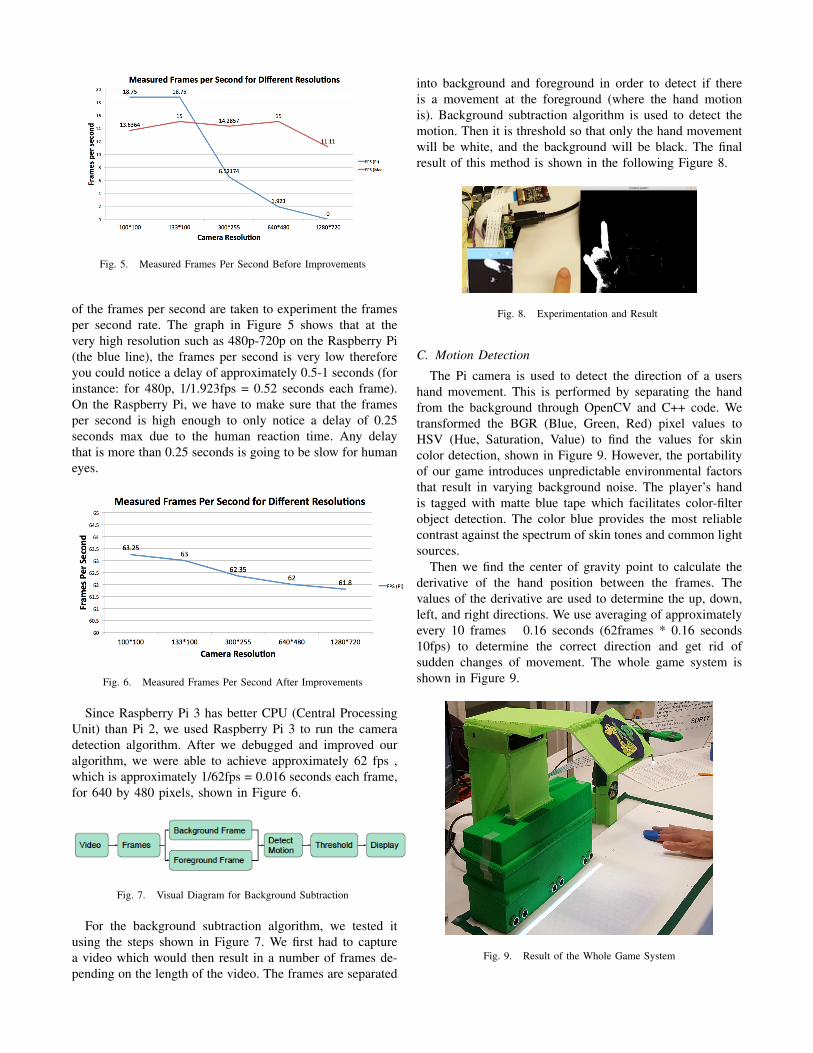
Fig. 5. Measured Frames Per Second Before Improvements
of the frames per second are taken to experiment the framesper second rate. The graph in Figure 5 shows that at thevery high resolution such as 480p-720p on the Raspberry Pi(the blue line), the frames per second is very low thereforeyou could notice a delay of approximately 0.5-1 seconds (forinstance: for 480p, 1/1.923fps = 0.52 seconds each frame).On the Raspberry Pi, we have to make sure that the framesper second is high enough to only notice a delay of 0.25seconds max due to the human reaction time. Any delaythat is more than 0.25 seconds is going to be slow for humaneyes.
Fig. 6. Measured Frames Per Second After Improvements
Since Raspberry Pi 3 has better CPU (Central ProcessingUnit) than Pi 2, we used Raspberry Pi 3 to run the cameradetection algorithm. After we debugged and improved ouralgorithm, we were able to achieve approximately 62 fps ,which is approximately 1/62fps = 0.016 seconds each frame,for 640 by 480 pixels, shown in Figure 6.
Fig. 7. Visual Diagram for Background Subtraction
For the background subtraction algorithm, we tested itusing the steps shown in Figure 7. We first had to capturea video which would then result in a number of frames de-pending on the length of the video. The frames are separated
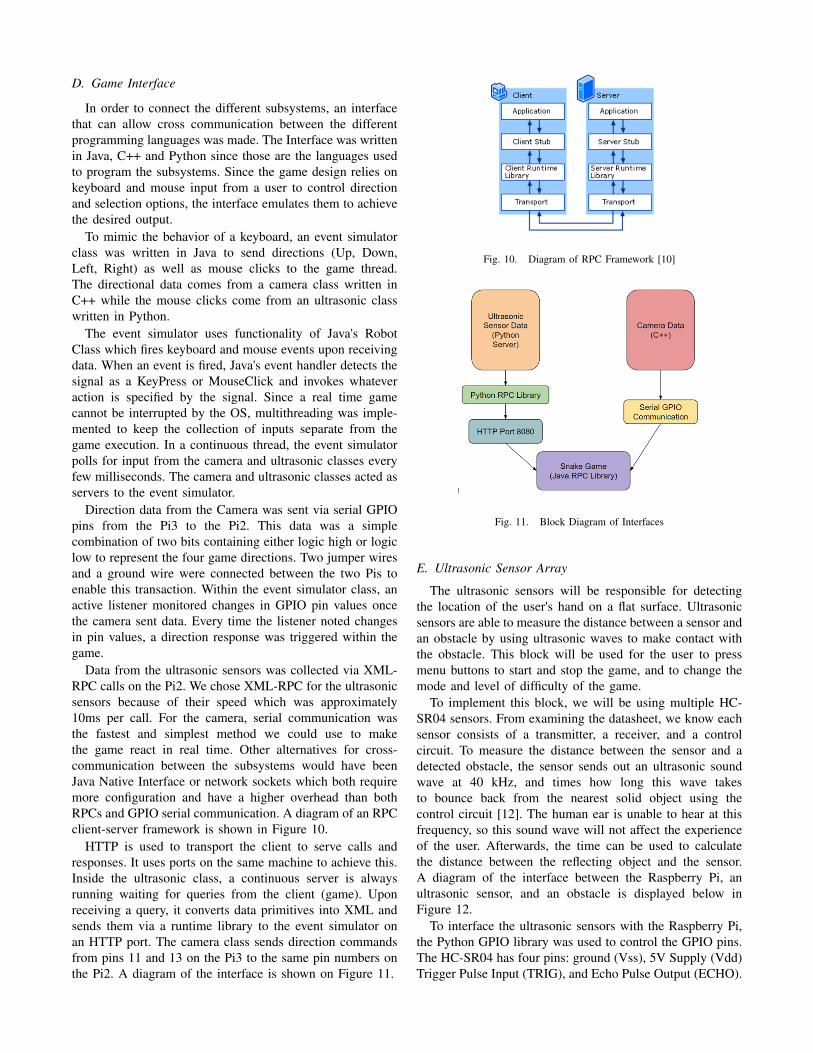
into background and foreground in order to detect if thereis a movement at the foreground (where the hand motionis). Background subtraction algorithm is used to detect themotion. Then it is threshold so that only the hand movementwill be white, and the background will be black. The finalresult of this method is shown in the following Figure 8.
Fig. 8. Experimentation and Result
C. Motion Detection
The Pi camera is used to detect the direction of a usershand movement. This is performed by separating the handfrom the background through OpenCV and C++ code. Wetransformed the BGR (Blue, Green, Red) pixel values toHSV (Hue, Saturation, Value) to find the values for skincolor detection, shown in Figure 9. However, the portabilityof our game introduces unpredictable environmental factorsthat result in varying background noise. The player’s handis tagged with matte blue tape which facilitates color-filterobject detection. The color blue provides the most reliablecontrast against the spectrum of skin tones and common lightsources.
Then we find the center of gravity point to calculate thederivative of the hand position between the frames. Thevalues of the derivative are used to determine the up, down,left, and right directions. We use averaging of approximatelyevery 10 frames 0.16 seconds (62frames * 0.16 seconds10fps) to determine the correct direction and get rid ofsudden changes of movement. The whole game system isshown in Figure 9.
Fig. 9. Result of the Whole Game System
D. Game Interface
In order to connect the different subsystems, an interfacethat can allow cross communication between the differentprogramming languages was made. The Interface was writtenin Java, C++ and Python since those are the languages usedto program the subsystems. Since the game design relies onkeyboard and mouse input from a user to control directionand selection options, the interface emulates them to achievethe desired output.
To mimic the behavior of a keyboard, an event simulatorclass was written in Java to send directions (Up, Down,Left, Right) as well as mouse clicks to the game thread.The directional data comes from a camera class written inC++ while the mouse clicks come from an ultrasonic classwritten in Python.
The event simulator uses functionality of Java's RobotClass which fires keyboard and mouse events upon receivingdata. When an event is fired, Java's event handler detects thesignal as a KeyPress or MouseClick and invokes whateveraction is specified by the signal. Since a real time gamecannot be interrupted by the OS, multithreading was imple-mented to keep the collection of inputs separate from thegame execution. In a continuous thread, the event simulatorpolls for input from the camera and ultrasonic classes everyfew milliseconds. The camera and ultrasonic classes acted asservers to the event simulator.
Direction data from the Camera was sent via serial GPIOpins from the Pi3 to the Pi2. This data was a simplecombination of two bits containing either logic high or logiclow to represent the four game directions. Two jumper wiresand a ground wire were connected between the two Pis toenable this transaction. Within the event simulator class, anactive listener monitored changes in GPIO pin values oncethe camera sent data. Every time the listener noted changesin pin values, a direction response was triggered within thegame.
Data from the ultrasonic sensors was collected via XML-RPC calls on the Pi2. We chose XML-RPC for the ultrasonicsensors because of their speed which was approximately10ms per call. For the camera, serial communication wasthe fastest and simplest method we could use to makethe game react in real time. Other alternatives for cross-communication between the subsystems would have beenJava Native Interface or network sockets which both requiremore configuration and have a higher overhead than bothRPCs and GPIO serial communication. A diagram of an RPCclient-server framework is shown in Figure 10.
HTTP is used to transport the client to serve calls andresponses. It uses ports on the same machine to achieve this.Inside the ultrasonic class, a continuous server is alwaysrunning waiting for queries from the client (game). Uponreceiving a query, it converts data primitives into XML andsends them via a runtime library to the event simulator onan HTTP port. The camera class sends direction commandsfrom pins 11 and 13 on the Pi3 to the same pin numbers onthe Pi2. A diagram of the interface is shown on Figure 11.
Fig. 10. Diagram of RPC Framework [10]
Fig. 11. Block Diagram of Interfaces
E. Ultrasonic Sensor Array
The ultrasonic sensors will be responsible for detectingthe location of the user's hand on a flat surface. Ultrasonicsensors are able to measure the distance between a sensor andan obstacle by using ultrasonic waves to make contact withthe obstacle. This block will be used for the user to pressmenu buttons to start and stop the game, and to change themode and level of difficulty of the game.
To implement this block, we will be using multiple HC-SR04 sensors. From examining the datasheet, we know eachsensor consists of a transmitter, a receiver, and a controlcircuit. To measure the distance between the sensor and adetected obstacle, the sensor sends out an ultrasonic soundwave at 40 kHz, and times how long this wave takesto bounce back from the nearest solid object using thecontrol circuit [12]. The human ear is unable to hear at thisfrequency, so this sound wave will not affect the experienceof the user. Afterwards, the time can be used to calculatethe distance between the reflecting object and the sensor.A diagram of the interface between the Raspberry Pi, anultrasonic sensor, and an obstacle is displayed below inFigure 12.
To interface the ultrasonic sensors with the Raspberry Pi,the Python GPIO library was used to control the GPIO pins.The HC-SR04 has four pins: ground (Vss), 5V Supply (Vdd)Trigger Pulse Input (TRIG), and Echo Pulse Output (ECHO).

Fig. 12. Visual Diagram of Raspberry Pi and HC-SR04 Interfacing [11]
To start a measurement, the Trigger pin is set to high for 10microseconds then set it low again, which then automaticallybegins a ranging program of eight bursts at 40 kHz. Next,the time that the ECHO pin was high was recorded, as thisdirectly corresponds to the distance between the sensor andthe nearest object. Therefore, making a measurement witha maximum distance of one meter takes approximately 6milliseconds. A timing diagram of a measurement for onesensor is displayed below in Figure 13.
Fig. 13. Timing Diagram of Ultrasonic Sensor Measurement
To calculate the distance between the sensor and thenearest object, we use the fact that the speed of sound is 343meters per second. We need to divide our measured time bytwo because this is the time for the ultrasonic pulse to gothe distance to the object and back again. Therefore, we usethe formula 34300 = Distance / (Time / 2) to calculate thedistance in centimeters between the sensor and the object.
Multiple ultrasonic sensors will be lined up at the baseof our system, facing towards the user. A common Triggersignal will be sent to each ultrasonic sensor, and each Echosignal will be used to determine the distance between anydetected object and each sensor. The sensor which recordsthe smallest distance, as well as the distance itself, willbe recorded and fed into the overall finite state machinewhich controls the game. These coordinates will be used
to determine whether a user has pressed one of the buttonswithin the game to start or stop the game, and change themodes and difficulties.
Circuit analysis techniques, as well as safety considera-tions such as proper grounding and voltage levels, will beused when building this block. These techniques stem fromcourses such as ECE 212: Circuit Analysis II, and the labo-ratory component of ECE 324: Electronics II. In addition,the design of systems which interface both software andhardware, such a microcontroller, a programming language,and circuitry, stem from techniques learned in ECE 353:Computer Systems Lab I.
In order to build this block, we studied the circuit ofthe HC-SR04 sensor and learned how to make a distancemeasurement using Python. We also had to design the waywhich multiple sensors would be used for our purpose. Wethen had to design a measurement algorithm which usesmultiple sensors, and implement the algorithm in Python.
To test the accuracy of a single measurement, we ran thePython program for a measurement using a single ultrasonicsensor and placed an obstacle in front of the sensor at variousdistances. We then measured these distances with a ruler andcompared the measured distance to the distances printed bythe Python program. Next, we ran the Python program fora measurement using multiple ultrasonic sensors and placedan object at various places along the line of sensors. Wemade sure that the sensor the obstacle was in front of wasrecorded, as well as the correct measured distance.
An diagram of the button pressing is shown below inFigure 14.
Fig. 14. Example of Button Detection
This data is then used to calculate which sensor the usershand is closest to, and how far away it is. This informationdetermines which button was pressed. Figure 15, shownbelow, is a diagram of the information flow for the ultrasonicsensors.
The index is an integer between 0 and 2 which representswhich sensor the obstacle was closest to, while the distanceis a float which represents the distance that the obstacle wasfrom the sensor.
This information gets sent via a Python XML-RPC serveron port 8080 into a Java XML-RPC client. Next, the infor-
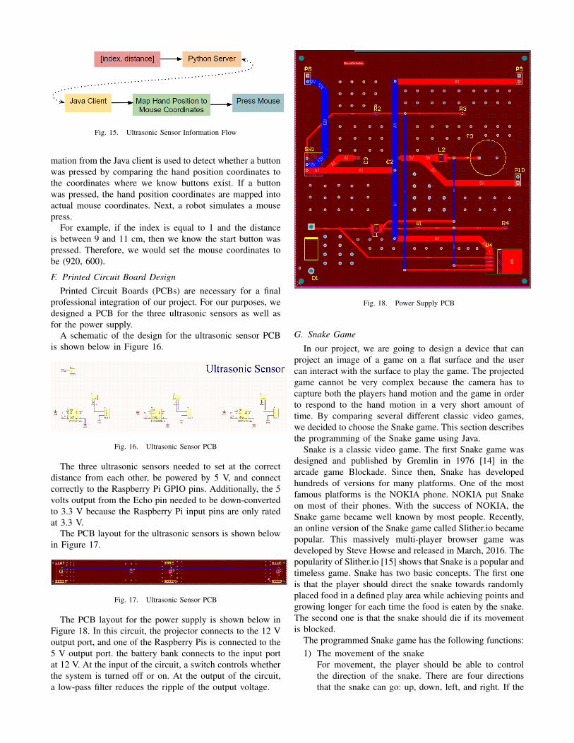
Fig. 15. Ultrasonic Sensor Information Flow
mation from the Java client is used to detect whether a buttonwas pressed by comparing the hand position coordinates tothe coordinates where we know buttons exist. If a buttonwas pressed, the hand position coordinates are mapped intoactual mouse coordinates. Next, a robot simulates a mousepress.
For example, if the index is equal to 1 and the distanceis between 9 and 11 cm, then we know the start button waspressed. Therefore, we would set the mouse coordinates tobe (920, 600).
F. Printed Circuit Board DesignPrinted Circuit Boards (PCBs) are necessary for a final
professional integration of our project. For our purposes, wedesigned a PCB for the three ultrasonic sensors as well asfor the power supply.
A schematic of the design for the ultrasonic sensor PCBis shown below in Figure 16.
Fig. 16. Ultrasonic Sensor PCB
The three ultrasonic sensors needed to set at the correctdistance from each other, be powered by 5 V, and connectcorrectly to the Raspberry Pi GPIO pins. Additionally, the 5volts output from the Echo pin needed to be down-convertedto 3.3 V because the Raspberry Pi input pins are only ratedat 3.3 V.
The PCB layout for the ultrasonic sensors is shown belowin Figure 17.
Fig. 17. Ultrasonic Sensor PCB
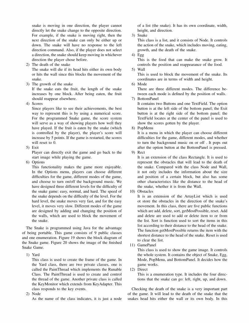
The PCB layout for the power supply is shown below inFigure 18. In this circuit, the projector connects to the 12 Voutput port, and one of the Raspberry Pis is connected to the5 V output port. the battery bank connects to the input portat 12 V. At the input of the circuit, a switch controls whetherthe system is turned off or on. At the output of the circuit,a low-pass filter reduces the ripple of the output voltage.
Fig. 18. Power Supply PCB
G. Snake Game
In our project, we are going to design a device that canproject an image of a game on a flat surface and the usercan interact with the surface to play the game. The projectedgame cannot be very complex because the camera has tocapture both the players hand motion and the game in orderto respond to the hand motion in a very short amount oftime. By comparing several different classic video games,we decided to choose the Snake game. This section describesthe programming of the Snake game using Java.
Snake is a classic video game. The first Snake game wasdesigned and published by Gremlin in 1976 [14] in thearcade game Blockade. Since then, Snake has developedhundreds of versions for many platforms. One of the mostfamous platforms is the NOKIA phone. NOKIA put Snakeon most of their phones. With the success of NOKIA, theSnake game became well known by most people. Recently,an online version of the Snake game called Slither.io becamepopular. This massively multi-player browser game wasdeveloped by Steve Howse and released in March, 2016. Thepopularity of Slither.io [15] shows that Snake is a popular andtimeless game. Snake has two basic concepts. The first oneis that the player should direct the snake towards randomlyplaced food in a defined play area while achieving points andgrowing longer for each time the food is eaten by the snake.The second one is that the snake should die if its movementis blocked.
The programmed Snake game has the following functions:1) The movement of the snake
For movement, the player should be able to controlthe direction of the snake. There are four directionsthat the snake can go: up, down, left, and right. If the
snake is moving in one direction, the player cannotdirectly let the snake change to the opposite direction.For example, if the snake is moving right, then thenext direction of the snake can only be either up ordown. The snake will have no response to the leftdirection command. Also, if the player does not selecta direction, the snake should keep moving in whicheverdirection the player chose before.
2) The death of the snakeThe snake will die if its head hits either its own bodyor hits the wall since this blocks the movement of thesnake.
3) The growth of the snakeIf the snake eats the fruit, the length of the snakeincreases by one block. After being eaten, the fruitshould reappear elsewhere.
4) ScoresSince players like to see their achievements, the bestway to represent this is by using a numerical score.For the programmed Snake game, the score systemwill serve as a way of showing players how well theyhave played. If the fruit is eaten by the snake (whichis controlled by the player), the player’s score willincrease by 5 points. If the game is restarted, the scoreswill reset to 0.
5) ExitPlayer can directly exit the game and go back to thestart image while playing the game.
6) OptionsThis functionality makes the game more enjoyable.In the Options menu, players can choose differentdifficulties for the game, different modes of the game,and choose to turn on/off the background music. Wehave designed three different levels for the difficulty ofthe snake game: easy, normal, and hard. The speed ofthe snake depends on the difficulty of the level. For thehard level, the snake moves very fast, and for the easylevel, it moves very slow. Different modes of the gameare designed by adding and changing the position ofthe walls, which are used to block the movement ofthe snake.
The Snake is programmed using Java for the advantageof being portable. This game consists of 9 public classesand one enumeration. Figure 19 shows the block diagram ofthe Snake game. Figure 20 shows the image of the finishedSnake Game.
1) YardThis class is used to create the frame of the game. Inthe Yard class, there are two private classes, one iscalled the PaintThread which implements the RunableClass. The PaintThread is used to create and controlthe thread of the game. Another private class is calledthe KeyMonitor which extends from KeyAdapter. Thisclass responds to the key events.
2) NodeAs the name of the class indicates, it is just a node
of a list (the snake). It has its own coordinate, width,height, and direction.
3) SnakeThis class is a list, and it consists of Node. It controlsthe action of the snake, which includes moving, eating,growth, and the death of the snake.
4) EggThis is the food that can make the snake grow. Itcontrols the position and reappearance of the food.
5) WallThis is used to block the movement of the snake. Itscoordinates are in terms of width and height.
6) ModeThere are three different modes. The difference be-tween each mode is defined by the position of walls.
7) BottomPanelIt contains two Buttons and one TextField. The optionbutton is at the left side of the bottom panel; the Exitbutton is at the right side of the bottom panel; theTextField locates at the center of the panel is used toshow the scores gotten by the player.
8) PopMenuIt is a menu in which the player can choose differentdifficulties for the game, different modes, and whetherto turn the background music on or off . It pops outafter the option button at the BottomPanel is pressed.
9) RectIt is an extension of the class Rectangle. It is used torepresent the obstacles that will lead to the death ofthe snake. Compared with the class Node and Wall,it not only includes the information about the sizeand position of a certain block, but also has someother characteristics like the distance to the head ofthe snake, whether it is from the Wall.
10) ObstaclesIt is an extension of the ArrayList which is usedot store the obstacles in the direction of the snake’smovement. In this class, there are five public functionswhich are add, delete, sort, getMostPossible, reset. Addand delete are used to add or delete item to or fromthe list. Sort is function used to sort the items in thislist according to their distance to the head of the snake.The function getMostPossible returns the item with theshortest distance to the head of the snake. Reset is usedto clear the list.
11) GamePanelThis class is used to show the game image. It controlsthe whole system. It contains the object of Snake, Egg,Mode, PopMenu, and BottomPanel. It decides how thegame works.
12) DirectThis is a enumeration type. It includes the four direc-tions that the snake can go: left, right, up, and down.
Checking the death of the snake is a very important partof the game. It will lead to the death of the snake that thesnakes head hits either the wall or its own body. In this
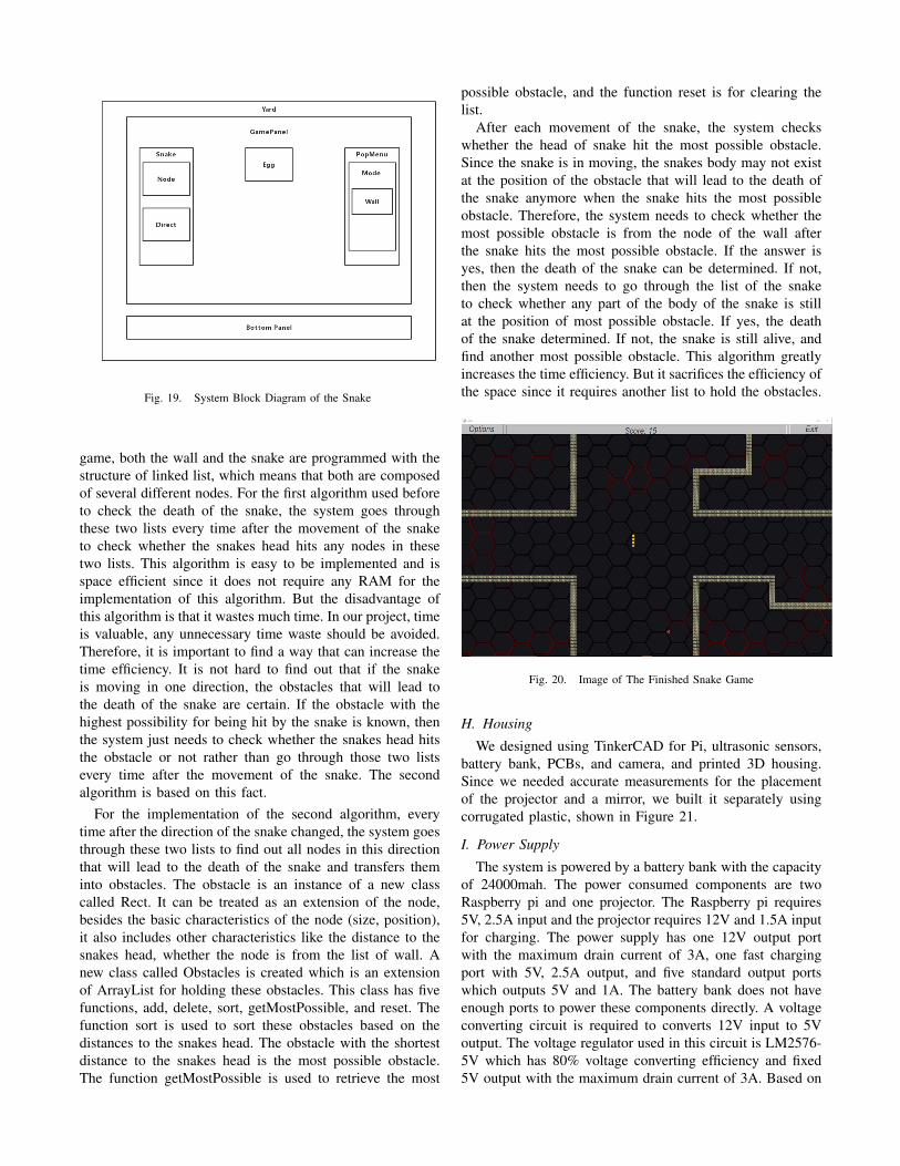
Fig. 19. System Block Diagram of the Snake
game, both the wall and the snake are programmed with thestructure of linked list, which means that both are composedof several different nodes. For the first algorithm used beforeto check the death of the snake, the system goes throughthese two lists every time after the movement of the snaketo check whether the snakes head hits any nodes in thesetwo lists. This algorithm is easy to be implemented and isspace efficient since it does not require any RAM for theimplementation of this algorithm. But the disadvantage ofthis algorithm is that it wastes much time. In our project, timeis valuable, any unnecessary time waste should be avoided.Therefore, it is important to find a way that can increase thetime efficiency. It is not hard to find out that if the snakeis moving in one direction, the obstacles that will lead tothe death of the snake are certain. If the obstacle with thehighest possibility for being hit by the snake is known, thenthe system just needs to check whether the snakes head hitsthe obstacle or not rather than go through those two listsevery time after the movement of the snake. The secondalgorithm is based on this fact.
For the implementation of the second algorithm, everytime after the direction of the snake changed, the system goesthrough these two lists to find out all nodes in this directionthat will lead to the death of the snake and transfers theminto obstacles. The obstacle is an instance of a new classcalled Rect. It can be treated as an extension of the node,besides the basic characteristics of the node (size, position),it also includes other characteristics like the distance to thesnakes head, whether the node is from the list of wall. Anew class called Obstacles is created which is an extensionof ArrayList for holding these obstacles. This class has fivefunctions, add, delete, sort, getMostPossible, and reset. Thefunction sort is used to sort these obstacles based on thedistances to the snakes head. The obstacle with the shortestdistance to the snakes head is the most possible obstacle.The function getMostPossible is used to retrieve the most
possible obstacle, and the function reset is for clearing thelist.
After each movement of the snake, the system checkswhether the head of snake hit the most possible obstacle.Since the snake is in moving, the snakes body may not existat the position of the obstacle that will lead to the death ofthe snake anymore when the snake hits the most possibleobstacle. Therefore, the system needs to check whether themost possible obstacle is from the node of the wall afterthe snake hits the most possible obstacle. If the answer isyes, then the death of the snake can be determined. If not,then the system needs to go through the list of the snaketo check whether any part of the body of the snake is stillat the position of most possible obstacle. If yes, the deathof the snake determined. If not, the snake is still alive, andfind another most possible obstacle. This algorithm greatlyincreases the time efficiency. But it sacrifices the efficiency ofthe space since it requires another list to hold the obstacles.
Fig. 20. Image of The Finished Snake Game
H. Housing
We designed using TinkerCAD for Pi, ultrasonic sensors,battery bank, PCBs, and camera, and printed 3D housing.Since we needed accurate measurements for the placementof the projector and a mirror, we built it separately usingcorrugated plastic, shown in Figure 21.
I. Power Supply
The system is powered by a battery bank with the capacityof 24000mah. The power consumed components are twoRaspberry pi and one projector. The Raspberry pi requires5V, 2.5A input and the projector requires 12V and 1.5A inputfor charging. The power supply has one 12V output portwith the maximum drain current of 3A, one fast chargingport with 5V, 2.5A output, and five standard output portswhich outputs 5V and 1A. The battery bank does not haveenough ports to power these components directly. A voltageconverting circuit is required to converts 12V input to 5Voutput. The voltage regulator used in this circuit is LM2576-5V which has 80% voltage converting efficiency and fixed5V output with the maximum drain current of 3A. Based on
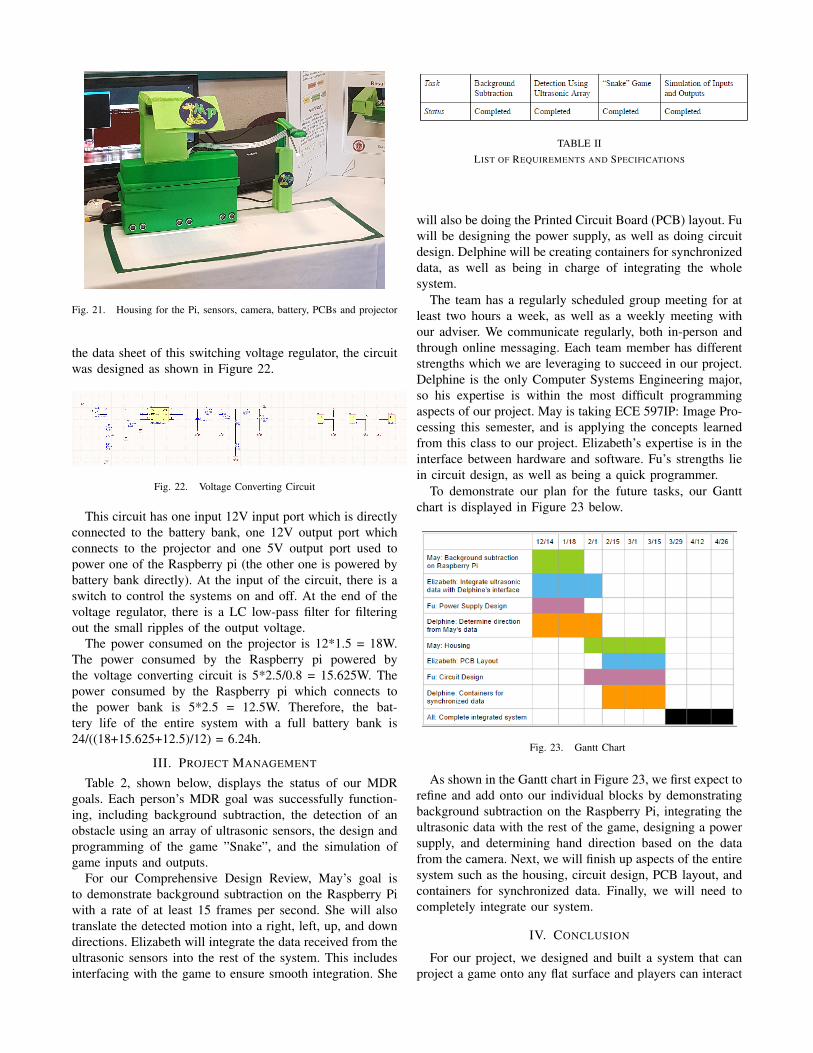
Fig. 21. Housing for the Pi, sensors, camera, battery, PCBs and projector
the data sheet of this switching voltage regulator, the circuitwas designed as shown in Figure 22.
Fig. 22. Voltage Converting Circuit
This circuit has one input 12V input port which is directlyconnected to the battery bank, one 12V output port whichconnects to the projector and one 5V output port used topower one of the Raspberry pi (the other one is powered bybattery bank directly). At the input of the circuit, there is aswitch to control the systems on and off. At the end of thevoltage regulator, there is a LC low-pass filter for filteringout the small ripples of the output voltage.
The power consumed on the projector is 12*1.5 = 18W.The power consumed by the Raspberry pi powered bythe voltage converting circuit is 5*2.5/0.8 = 15.625W. Thepower consumed by the Raspberry pi which connects tothe power bank is 5*2.5 = 12.5W. Therefore, the bat-tery life of the entire system with a full battery bank is24/((18+15.625+12.5)/12) = 6.24h.
III. PROJECT MANAGEMENT
Table 2, shown below, displays the status of our MDRgoals. Each person’s MDR goal was successfully function-ing, including background subtraction, the detection of anobstacle using an array of ultrasonic sensors, the design andprogramming of the game ”Snake”, and the simulation ofgame inputs and outputs.
For our Comprehensive Design Review, May’s goal isto demonstrate background subtraction on the Raspberry Piwith a rate of at least 15 frames per second. She will alsotranslate the detected motion into a right, left, up, and downdirections. Elizabeth will integrate the data received from theultrasonic sensors into the rest of the system. This includesinterfacing with the game to ensure smooth integration. She
TABLE IILIST OF REQUIREMENTS AND SPECIFICATIONS
will also be doing the Printed Circuit Board (PCB) layout. Fuwill be designing the power supply, as well as doing circuitdesign. Delphine will be creating containers for synchronizeddata, as well as being in charge of integrating the wholesystem.
The team has a regularly scheduled group meeting for atleast two hours a week, as well as a weekly meeting withour adviser. We communicate regularly, both in-person andthrough online messaging. Each team member has differentstrengths which we are leveraging to succeed in our project.Delphine is the only Computer Systems Engineering major,so his expertise is within the most difficult programmingaspects of our project. May is taking ECE 597IP: Image Pro-cessing this semester, and is applying the concepts learnedfrom this class to our project. Elizabeth’s expertise is in theinterface between hardware and software. Fu’s strengths liein circuit design, as well as being a quick programmer.
To demonstrate our plan for the future tasks, our Ganttchart is displayed in Figure 23 below.
Fig. 23. Gantt Chart
As shown in the Gantt chart in Figure 23, we first expect torefine and add onto our individual blocks by demonstratingbackground subtraction on the Raspberry Pi, integrating theultrasonic data with the rest of the game, designing a powersupply, and determining hand direction based on the datafrom the camera. Next, we will finish up aspects of the entiresystem such as the housing, circuit design, PCB layout, andcontainers for synchronized data. Finally, we will need tocompletely integrate our system.
IV. CONCLUSION
For our project, we designed and built a system that canproject a game onto any flat surface and players can interact

with the surface to play the game. We divided the project intoseveral different parts: motion detection, location detection,game, and game interfaces. May is responsible for the motiondetection. May chose to use a Pi camera which is attachedto the Raspberry Pi board and captures hand motion. Withthe implementation of background subtraction algorithm withOpen CV libraries and C++ programming language, the handmotion can be detected in a very short time. Also, May hasbuilt the house for the projector with 3D printing. Elizabethis responsible for location detection. To accomplish this,she chose to use ultrasonic sensors. The ultrasonic sensorscan measure the distance between a sensor and an obstacle,which can then be used to determine the location of a playershand. She chose several HC-SR04 sensors to do the work andprogrammed them in Python with the help of Python GIOlibrary. Elizabeth also designed and built the PCB for theultrasonic and power supply circuit. Fu is responsible forthe snake game. Fu programmed the classic game, Snakewith the implementation of JAVA GUI. Based on the datasheet, Fu also designed the power supply circuit. Delphineis responsible for the game interfaces and integration of thedifferent subsystems. Initially, he simulated the inputs fromthe pi camera and the ultrasonic sensors to the game andmade the snake game respond to them accordingly. For ourfinal product, it weighs 3.5 pounds with the size of 17 by 30centimeters. The whole system had only 0.197s delay at arate of 62 frames per second. On a full charged battery, theentire system can run for 6.2 hours. The project cost $386.4in total which is a very reasonable price.
ACKNOWLEDGMENT
We would like to thank the following people for theircontribution to our project: Professor Holcomb, for assistingus with considerations concerning image processing and ourmicrocontroller; Professor Hollot, for helping us evaluate thedesign and creativity of our project; and Professor Bardin,for supporting and guiding us through the entire process.
REFERENCES
[1] ”The History of the Classroom Blackboard.” Concordia Portland.[Online]. Available at: http://education.cu-portland.edu/blog/reference-material/the-history-of-the-classroom-blackboard/. [Accessed: 19 Dec.2016].
[2] ”Professional Resources.” Interactive Whiteboards EnhanceClassroom Instruction and Learning. [Online]. Available at:https://www.neamb.com/professional-resources/benefits-of-interactive-whiteboards.htm. [Accessed: 20 Dec. 2016].
[3] ”EyePlay Interactive Game Floor.” Motion Fitness. [Online]. Availableat: http://www.motionfitness.com/EyePlay-Interactive-Game-Floor-p/eyeplay.htm. [Accessed: 20 Dec. 2016].
[4] Megrabbitt. ”How Interactive Floor Projection SystemsWork.” Meg of PO-MO Inc. [Online]. Available at:http://megrabbitt.tumblr.com/post/20917005071/how-interactive-floor-projection-systems-work. 11 Apr. 2012. [Accessed: 21 Dec.2016].
[5] ”Experiment: How Fast Your Brain Reacts To Stimuli.” Experiment:How Fast Your Brain Reacts To Stimuli. [Online]. Available at:https://backyardbrains.com/experiments/reactiontimeprettyPhoto. [Ac-cessed: 22 Dec. 2016].
[6] Raspberry Pi. Bonn: Rheinwerk; Rhein-werk Computing, 2015. [Online]. Available at:http://cdn.sparkfun.com/datasheets/Dev/RaspberryPi/RPiCamMod2.pdf.[Accessed: 5 Feb. 2017].
[7] ”Motion Analysis and Object Tracking.” Motion Analysis and Ob-ject Tracking OpenCV 2.4.13.2 Documentation. [Online]. Availableat: http://docs.opencv.org/2.4/modules/refman.html. [Accessed: 5 Feb.2017].
[8] ”What Is the Fastest Human Reaction Time?” [Online]. Avail-able at: https://www.reference.com/science/fastest-human-reaction-time-744b62945476fb5dReference. [Accessed: 22 Dec. 2016].
[9] CMake. [Online]. Available: https://cmake.org/. [Accessed: 5 Feb.2017].
[10] Microsoft, ”How RPC works,” 2016. [Online]. Available:https://technet.microsoft.com/en-us/library/cc738291(v=ws.10).aspx.Accessed: Dec. 23, 2016.
[11] A. K. Ravi, ”How to Use Ultrasonic Sensor HC SR04 in Arduino,”May 2015. [Online]. Accessed: Dec. 19, 2016.
[12] E. Freaks, SparkFun Electronics. [Online]. Available:https://cdn.sparkfun.com/datasheets/Sensors/Proximity/HCSR04.pdf.Accessed: Jan. 24, 2017.
[13] Eckel, Bruce. Thinking in Java. Upper Saddle River, NJ: Prentice Hall,2006. Print.
[14] O.S.Games, ”Snake (video game),” in WikiPedia, Wikimedia Foun-dation, 2017.[Online], Available: https://en.wikipedia.org/wiki/Snake.Accessed; Feb.6,2017.
[15] ”Slither.io,” in Wikipedia, Wikimedia Foundation, 2017. [Online].Available: https://en.wikipedia.org/wiki/Slither.io. Accessed: Feb. 6,2017.
[16] Freeman, E., Robson, E., Sierra, K., and Bates, B. (2004). Head Firstdesign patterns. Sebastopol, CA: O’Reilly.
[17] Raspberry Pi 3 Model B. 2017. [Online]. Available: http://docs-europe.electrocomponents.com/webdocs/14ba/0900766b814ba5fd.pdf.Accessed: Feb. 6, 2017.