Embed Size (px)
Citation preview

ServoWorks S-100T/S-120T
Operator’s Manual
Revision 1.42 © 2014 Soft Servo Systems, Inc.

SERVOWORKS S-100T/S-120T OPERATOR’S MANUAL
Warning / Important Notice
_____________________________________________________________________________________
i
Warning
The product described herein has the potential – through misuse, inattention, or lack of understanding – to create
conditions that could result in personal injury, damage to equipment, or damage to the product(s) described herein.
Machinery in motion and high-power, high-current servo drives can be dangerous; potentially hazardous situations
such as runaway motors could result in death; burning or other serious personal injury to personnel; damage to
equipment or machinery; or economic loss if procedures aren’t followed properly. Soft Servo Systems, Inc. assumes
no liability for any personal injury, property damage, losses or claims arising from misapplication of its products. In
no event shall Soft Servo Systems, Inc. or its suppliers be liable to you or any other person for any incidental
collateral, special or consequential damages to machines or products, including without limitation, property damage,
damages for loss of profits, loss of customers, loss of goodwill, work stoppage, data loss, computer failure or
malfunction claims by any party other than you, or any and all similar damages or loss even if Soft Servo Systems,
Inc., its suppliers, or its agent has been advised of the possibility of such damages.
It is therefore necessary for any and all personnel involved in the installation, maintenance, or use of these products
to thoroughly read this pamphlet and related manuals and understand their contents. Soft Servo Systems, Inc. stands
ready to answer any questions or clarify any confusion related to these products in as timely a manner as possible.
The selection and application of Soft Servo Systems, Inc.’s products remain the responsibility of the equipment
designer or end user. Soft Servo Systems, Inc. accepts no responsibility for the way its controls are incorporated
into a machine tool or factory automation setting. Any documentation and warnings provided by Soft Servo
Systems, Inc. must be promptly provided to any end users.
This document is based on information that was available at the time of publication. All efforts have been made to
ensure that this document is accurate and complete. However, due to the widely varying uses of this product, and
the variety of software and hardware configurations possible in connection with these uses, the information
contained in this manual does not purport to cover every possible situation, contingency or variation in hardware or
software configuration that could possibly arise in connection with the installation, maintenance, and use of the
products described herein. Soft Servo Systems, Inc. assumes no obligations of notice to holders of this document
with respect to changes subsequently made. Under no circumstances will Soft Servo Systems, Inc. be liable for any
damages or injuries resulting from any defect or omission in this manual.
Soft Servo Systems, Inc. makes no representation or warranty, expressed, implied, or statutory with respect to, and
assumes no responsibility for the accuracy, completeness, sufficiency, or usefulness of the information contained
herein. NO IMPLIED WARRANTIES OF MERCHANTABILITY OR FITNESS OF PURPOSE SHALL APPLY.

SERVOWORKS S-100T/S-120T OPERATOR’S MANUAL
Warning / Important Notice
_____________________________________________________________________________________
ii
Important Notice
The information contained in this manual is intended to be used only for the purposes agreed upon in the related
contract with Soft Servo Systems, Inc. All material contained herein is subject to restricted rights and restrictions
set forth in the contract between the parties.
These manuals contain confidential and proprietary information that is not to be shared with, nor distributed to, third
parties by any means without the prior express, written permission of Soft Servo Systems, Inc. No materials
contained herein are to be duplicated or reproduced in whole or in part without the express, written permission of
Soft Servo Systems, Inc.
Although every effort and precaution has been taken in preparing this manual, the information contained herein is
subject to change without notice. This is because Soft Servo Systems, Inc. is constantly striving to improve its
products. Soft Servo Systems, Inc. assumes no responsibility for errors or omissions.
All rights reserved. Any violations of contractual agreements pertaining to the materials herein will be prosecuted to
the full extent of the law.

SERVOWORKS S-100T/S-120T OPERATOR’S MANUAL
Contents
_____________________________________________________________________________________
iii
Table of Contents
Warning ............................................................................................................................................................................................ i Important Notice ............................................................................................................................................................................. ii Table of Contents .......................................................................................................................................................................... iii List of Tables.................................................................................................................................................................................. vi List of Figures ................................................................................................................................................................................ vi Chapter 1: Welcome to ServoWorks S-100T/S-120T ................................................................................................................ 1-1
1.1 Overview of ServoWorks ServoWorks S-100T/S-120T ................................................................................. 1-1 1.2 What You Can Do With ServoWorks S-100T/S-120T ................................................................................... 1-2 1.3 Differences Between ServoWorks S-100T and ServoWorks S-120T ............................................................. 1-2 1.4 ServoWorks S-100T/S-120T Simulation Edition ........................................................................................... 1-3 1.5 Using ServoWorks S-100T/S-120T with general Panel PCs with Function Keys .......................................... 1-3 1.6 Selecting Toolbar Buttons ............................................................................................................................... 1-4
Chapter 2: Starting ServoWorks S-100T/S-120T ....................................................................................................................... 2-1 2.1 Starting ServoWorks S-100T/S-120T ............................................................................................................. 2-1 2.2 Navigating Control Modes in ServoWorks S-100T/S-120T ........................................................................... 2-3 2.3 Turning On and Off the Servo Drives ............................................................................................................. 2-7 2.4 Performing a Homing Operation ..................................................................................................................... 2-8
Chapter 3: Configuring the System and Program Parameters ................................................................................................ 3-1 3.1 Overview ......................................................................................................................................................... 3-1 3.2 Navigating in Configuration Mode ................................................................................................................. 3-2 3.3 Making Changes to Parameters....................................................................................................................... 3-5
3.3.1 Navigating Among the Frames and Text Boxes...................................................................................... 3-5 3.3.2 Selecting From Among Options in a Frame ............................................................................................ 3-6 3.3.3 Changing Values in the Text Boxes ........................................................................................................ 3-6 3.3.4 Saving Your Changes to Parameters ....................................................................................................... 3-7 3.3.5 Setting A Set of Parameters Back to the Default Settings ....................................................................... 3-7
3.4 Setting General Parameters (Including the Unit of Measurement) ................................................................. 3-8 3.4.1 Overview ................................................................................................................................................. 3-8 3.4.2 Program Parameters ................................................................................................................................ 3-9 3.4.3 Operator’s Panel Parameters ................................................................................................................. 3-10 3.4.4 Machine Unit Parameters ...................................................................................................................... 3-10 3.4.5 Thread Cutting Parameters for G92 and G76 ........................................................................................ 3-10 3.4.6 Shut Down Parameters .......................................................................................................................... 3-10 3.4.7 Password Settings.................................................................................................................................. 3-10 3.4.8 Tool Measurer Parameters .................................................................................................................... 3-11
3.5 Setting Servo Control Parameters ................................................................................................................. 3-11 3.6 Setting Parameters for Safe Zones ................................................................................................................ 3-15 3.7 Setting Smoothing Filter Parameters ............................................................................................................ 3-17 3.8 Setting Parameters Related to Machine Error Compensation ....................................................................... 3-20 3.9 Setting Parameters for Feedrates ................................................................................................................... 3-22 3.10 Setting Home Parameters ............................................................................................................................ 3-23 3.11 Setting HandWheel Parameters .................................................................................................................. 3-24 3.12 Setting Spindle Parameters ......................................................................................................................... 3-25 3.13 Setting I/O Parameters (for VersioBus) ...................................................................................................... 3-29
3.13.1 Overview ............................................................................................................................................. 3-29 3.13.2 Viewing I/O Signals in I/O Mode ....................................................................................................... 3-29 3.13.3 Changing I/O Signals .......................................................................................................................... 3-31
3.14 Setting M Code Parameters......................................................................................................................... 3-32 3.15 Using the Parameter Manager ..................................................................................................................... 3-37
3.15.1 Overview ............................................................................................................................................. 3-37 3.15.2 Selecting a File To Copy, Move, Remove, Rename, Create or Restore .............................................. 3-37 3.15.3 Creating a Registry File ...................................................................................................................... 3-38 3.15.4 Copying, Moving, Removing, Renaming or Restoring Registry Files ................................................ 3-38

SERVOWORKS S-100T/S-120T OPERATOR’S MANUAL
Contents
_____________________________________________________________________________________
iv
3.16 Setting Display Parameters ......................................................................................................................... 3-40 3.17 Setting Auto Plot Parameters ...................................................................................................................... 3-41 3.18 Setting Color Parameters ............................................................................................................................ 3-42
3.18.1 Overview ............................................................................................................................................. 3-42 3.18.2 Accessing the Color Parameters .......................................................................................................... 3-42 3.18.3 What Elements of the Screen Can You Change? ................................................................................ 3-43 3.18.4 The Interface Display .......................................................................................................................... 3-44 3.18.5 The Button Display ............................................................................................................................. 3-45 3.18.6 The Plot Display .................................................................................................................................. 3-47 3.18.7 The G-Code Display ........................................................................................................................... 3-49 3.18.8 The Data Display................................................................................................................................. 3-50 3.18.9 Selecting and Changing the Color Parameters .................................................................................... 3-51 3.18.10 Saving Your Color Settings ............................................................................................................... 3-53 3.18.11 Setting All the Color Parameters Back to the Default Settings ......................................................... 3-54 3.18.12 Exiting the Color Parameters Display Area ...................................................................................... 3-54
3.19 Exiting Configuration Mode ....................................................................................................................... 3-54 Chapter 4: Monitoring the Status of Operations ....................................................................................................................... 4-1
4.1 Understanding the General Status of the Lathe ............................................................................................... 4-1 4.1.1 Overview ................................................................................................................................................. 4-1 4.1.2 Cycle Time Indicator ............................................................................................................................... 4-2 4.1.3. Spindle Status Indicator ......................................................................................................................... 4-2 4.1.4 Feedrate Indicator.................................................................................................................................... 4-2 4.1.5 Locks Status Indicators ........................................................................................................................... 4-2 4.1.6 Servo Loop Status Indicator .................................................................................................................... 4-2 4.1.7 Servo Drives On/Off Status Indicators .................................................................................................... 4-2 4.1.8 Home Status Indicators (Is the Axis at the Home Position?) .................................................................. 4-3 4.1.9 Override Status Indicators (What Are the Current Override Settings?) ................................................. 4-3 4.1.10 Overtravel Status Indicators (Have the Software Limits Been Reached?) ........................................... 4-3
4.2 Specifying Information to Display in the Main Display Area ........................................................................ 4-3 4.2.1 What Information Is Available to Be Displayed? ................................................................................... 4-3
4.2.1.1 Position Information About Each Axis ........................................................................................... 4-3 4.2.1.2 Clearing the Relative Positions ....................................................................................................... 4-4 4.2.1.3 A Plot of Tool Trajectory ................................................................................................................ 4-4 4.2.1.4 Statistics Information ...................................................................................................................... 4-4 4.2.1.5 Setting the Timer ............................................................................................................................. 4-5 4.2.1.6 Switches Information ...................................................................................................................... 4-5 4.2.1.7 Digital Local I/O for the VersioBus Adapter Board ........................................................................ 4-5 4.2.1.8 Digital I/O for the Servo Interface Module ..................................................................................... 4-6 4.2.1.9 Digital I/O for the IM-200 ............................................................................................................... 4-6
4.2.2 Using Screen Mode to Select Information to Display in the Main Display Area.................................... 4-7 4.2.3 Exiting Screen Mode ............................................................................................................................... 4-9
4.3 Plotting Motion (Using Plot Mode) .............................................................................................................. 4-10 4.3.1 Overview ............................................................................................................................................... 4-10 4.3.2 Viewing a Plot ....................................................................................................................................... 4-10 5.3.3 Changing the Orientation (Plane) of a Plot ........................................................................................... 4-11 4.3.4 Changing the Scale of a Plot (Zooming In and Out) ............................................................................. 4-12 4.3.5 Moving the Plot Within the Plot Area ................................................................................................... 4-12 4.3.6 Clearing a Plot ....................................................................................................................................... 4-13 4.3.7 Holding a Plot ....................................................................................................................................... 4-13 4.3.8 Exiting Plot Mode ................................................................................................................................. 4-13
Chapter 5: Manually Operating the Lathe .................................................................................................................................. 5-1 5.1 Overview ......................................................................................................................................................... 5-1 5.2 Using the Machine Lock and Interlock Switches............................................................................................ 5-2
5.2.1 Using the Machine Lock Switch in a Manual Mode ............................................................................... 5-2 5.2.2 Using the Interlock Switch in a Manual Mode ........................................................................................ 5-3 5.2.3 The Difference Between the Machine Lock and Interlock Switches ...................................................... 5-4

SERVOWORKS S-100T/S-120T OPERATOR’S MANUAL
Contents
_____________________________________________________________________________________
v
Chapter 6: Starting and Stopping the Spindle (Using Spindle Mode) .................................................................................... 6-1 Chapter 7: Continuous Jogging (Using Jog Continuous Mode) ............................................................................................. 7-1 Chapter 8: Incremental Jogging (Using Jog Incremental Mode) ............................................................................................ 8-1 Chapter 9: Rapid Positioning (Using Rapid Mode) ................................................................................................................... 9-1 Chapter 10: Manual Data Input (Using MDI Mode) .................................................................................................................. 10-1
10.1 Overview of MDI Mode ............................................................................................................................. 10-1 10.2 Getting into MDI Mode: ............................................................................................................................. 10-1 10.3 Using the G Code and M Code Reference Tools ........................................................................................ 10-2 10.4 Entering and Executing Commands in MDI Mode ..................................................................................... 10-3 10.5 Viewing the Command Log ........................................................................................................................ 10-4
Chapter 11: Using HandWheel Mode ....................................................................................................................................... 11-1 Chapter 12: Creating, Editing and Manipulating Part Programs ........................................................................................... 12-1
12.1 Overview ..................................................................................................................................................... 12-1 12.2 Getting Into Editor Mode ............................................................................................................................ 12-1 12.3 Using the G Code and M Code Reference Tools ........................................................................................ 12-3 12.4 Selecting a File To Edit ............................................................................................................................... 12-4 12.5 Editing Part Programs ................................................................................................................................. 12-6
12.5.1 Using the Editor and Keypad .............................................................................................................. 12-6 12.5.2 Edit Functions ..................................................................................................................................... 12-6
13.6 Using the Find Tool .................................................................................................................................... 12-7 12.7 Saving Your File After Editing ................................................................................................................... 12-8 12.8 Manipulating Part Program Files ................................................................................................................ 12-9
12.8.1 Backing Up a Part Program File ......................................................................................................... 12-9 12.8.2 Moving a Part Program File .............................................................................................................. 12-11 12.8.3 Deleting a Part Program File ............................................................................................................. 12-12 12.8.4 Renaming a Part Program File .......................................................................................................... 12-13
12.9 Exiting Editor Mode ................................................................................................................................. 12-15 Chapter 13: Proving Part Programs and Running Production .............................................................................................. 13-1
13.1 Overview of Auto Mode and CNC Part Programming ............................................................................... 13-1 13.2 Opening and Closing a Part Program .......................................................................................................... 13-3 13.3 Setting Feed Override and Rapid Override ................................................................................................. 13-5 13.4 Setting the Operation Support Function Switches ...................................................................................... 13-6
13.4.1 Overview ............................................................................................................................................. 13-6 13.4.2 Dry Run ............................................................................................................................................... 13-6 13.4.3 Optional Skip ...................................................................................................................................... 13-6 13.4.4 Optional Stop ...................................................................................................................................... 13-7 13.4.5 Single Block ........................................................................................................................................ 13-7 13.4.6 MST Codes Lock ................................................................................................................................ 13-7
13.5 Using the Handwheel to Interrupt Program Execution ............................................................................... 13-8 13.6 Proving a Part Program ............................................................................................................................... 13-9
13.6.1 Proving a Part Program Using the Machine Lock Switch ................................................................... 13-9 13.6.2 Proving a Part Program Using the Interlock Switch ......................................................................... 13-10 13.6.3 The Difference Between the Machine Lock and Interlock Switches ................................................ 13-12 13.6.4 Proving a Part Program Using the Dry Run Switch .......................................................................... 13-13
13.7 Setting Tool Offsets .................................................................................................................................. 13-14 13.7.1 Overview ........................................................................................................................................... 13-14 13.7.2 Accessing the Tool Offsets ............................................................................................................... 13-17 13.7.3 Manually Setting Tool Offsets .......................................................................................................... 13-19
13.7.3.1 Moving Between the Text Boxes .............................................................................................. 13-19 13.7.3.2 Changing Values in the Text Boxes .......................................................................................... 13-20 13.7.3.3 Saving Your Changes ................................................................................................................ 13-20
13.7.4 Inputting Part Dimensions and Gauge Template Thickness.............................................................. 13-20 13.7.5 Automatically Setting Tool Geometry Offsets Using Touch Offs .................................................... 13-21
13.7.5.1 Starting the Process of Setting Tool Geometry Offsets ............................................................. 13-22 13.7.5.2 Selecting the Tool Offset ........................................................................................................... 13-22 13.7.5.3 Starting the Spindle Rotation ..................................................................................................... 13-22

SERVOWORKS S-100T/S-120T OPERATOR’S MANUAL
Contents
_____________________________________________________________________________________
vi
13.7.5.4 Turning on the HandWheel and Touching Off the Z and X Axes ............................................. 13-23 13.7.5.5 Finishing the Setting of the Tool Geometry Offsets .................................................................. 13-25
13.7.6 Automatically Setting Tool Geometry Offsets Using Tool Measuring Sensors ............................... 13-26 13.7.7 Calculating Tool Wear Offsets .......................................................................................................... 13-26 13.7.8 Exiting Offset Mode .......................................................................................................................... 13-27
13.8 Setting the External Zero Offset and Workpiece Zero Point Offsets ........................................................ 13-27 13.8.1 What Is An External Zero Offset? ..................................................................................................... 13-27 13.8.2 What Are Workpiece Zero Point Offsets (Workpiece Coordinates)? ............................................... 13-28 13.8.3 Accessing the External Zero Offset and the Work Point Coordinates .............................................. 13-28 13.8.4 Selecting and Changing the Input for the Work Point Parameters .................................................... 13-30
13.8.4.1 Moving Between the Text Boxes .............................................................................................. 13-30 13.8.4.2 Changing Values in the Text Boxes .......................................................................................... 13-30 13.8.4.3 Saving Your Changes ................................................................................................................ 13-30 13.8.4.4 Setting the Workpiece Coordinates Back to the Default Settings ............................................. 13-30 13.8.4.5 Exiting Coordinates/Counter Mode ........................................................................................... 13-31
13.9 Setting the Part Counter Options .............................................................................................................. 13-31 13.9.1 Accessing the Part Counter Frames................................................................................................... 13-31 13.9.2 Specifying Counter Options .............................................................................................................. 13-31 13.9.3 Exiting Counter/Coordinates Mode .................................................................................................. 13-32
13.10 Running Production ................................................................................................................................ 13-32 13.10.1 Production Run Checklist................................................................................................................ 13-32 13.10.2 Executing a Part Program ................................................................................................................ 13-33 13.10.3 Rewinding or Fast Forwarding a Part Program ............................................................................... 13-33
13.11 Exiting Auto Mode ................................................................................................................................. 13-35 Chapter 14: Exiting ServoWorks S-100T/S-120T .................................................................................................................... 14-1
14.1 Exiting from Main Mode ............................................................................................................................ 14-1 14.2 Exiting from an Operational Mode ............................................................................................................. 14-2 14.3 Exiting from a Sub Mode ............................................................................................................................ 14-3
14.3.1 If You Entered the Sub Mode From Main Mode ................................................................................ 14-3 14.3.2 If You Entered the Sub Mode From An Operational Mode ................................................................ 14-4
Chapter 15: Troubleshooting .................................................................................................................................................... 15-1 15.1 Resetting ServoWorks S-100T/S-120T If E-STOP Is Activated ................................................................ 15-1 15.2 Using the Flight Recorder for Debugging ................................................................................................... 15-3 15.3 If the Homing Operation Does Not Seem to Work…. ................................................................................ 15-4
Chapter 16: Alarms .................................................................................................................................................................... 16-1 16.1 Alarms ......................................................................................................................................................... 16-1 16.2 List of Alarms ............................................................................................................................................. 16-1
Index ............................................................................................................................................................................................... IV
List of Tables
Table 1-1: Keyboard Shortcuts for Selecting Toolbar Buttons .................................................................................. 1-7 Table 1-1: Packing List and Product Registration Numbers ...................................................................................... 1-7 Table 4-1: Screen Mode Options (1 of 2) .................................................................................................................. 4-8 Table 4-2: Screen Mode Options (2 of 2) .................................................................................................................. 4-9 Table 11-1: Axis Selection Switch Settings for Machine Axes for the HW-100 HandWheel ................................. 11-5 Table 13-1: Operation Support Switches ................................................................................................................. 13-6
List of Figures
Figure 1-1: ServoWorks S-1_0T using Panel PC with Function Key Interface ........................................................ 1-4 Figure 1-2: Keys Used to Selecting Toolbar Buttons – Typical QWERTY Keyboard ............................................. 1-5 Figure 1-3: Keyboard Shortcuts for Selecting Toolbar Buttons ................................................................................ 1-6

SERVOWORKS S-100T/S-120T OPERATOR’S MANUAL
Contents
_____________________________________________________________________________________
vii
Figure 2-1: ServoWorks S-1_0T Welcome Window ................................................................................................. 2-1 Figure 2-2: The Main Window of ServoWorks S-1_0T ............................................................................................ 2-2 Figure 2-3: The RtxServer Window .......................................................................................................................... 2-3 Figure 2-4: Flow Chart for Navigating Control Modes – Option #1: Entering an Operational Mode from Main Mode
......................................................................................................................................................................... 2-5 Figure 2-5: Flow Chart for Navigating Control Modes – Option #2: Entering a Sub Mode from Main Mode ......... 2-6 Figure 2-6: Mode Information Displayed in ServoWorks S-1_0T ............................................................................ 2-7 Figure 2-7: The Home Mode Window ...................................................................................................................... 2-9 Figure 3-1: The Password Prompt Window............................................................................................................... 3-2 Figure 3-2: The Configuration Mode Window .......................................................................................................... 3-3 Figure 3-3: Example Frame with Settings for the X and Z Axes ............................................................................... 3-6 Figure 3-4: Example Frame with Options ................................................................................................................. 3-6 Figure 3-5: The General Parameters Display Area (1 of 2) ....................................................................................... 3-8 Figure 3-6: The General Parameters Display Area (2 of 2) ....................................................................................... 3-9 Figure 3-7: Top View of a Lathe Showing X+ Direction: Near Side and Far Side ................................................. 3-10 Figure 3-8: The Servo Control Parameters Display Area #1 ................................................................................... 3-11 Figure 3-9: The Servo Control Parameters Display Area #1 Showing A Servo Control Plot (1 of 2) .................... 3-12 Figure 3-10: The Servo Control Parameters Display Area #1 Showing A Servo Control Plot (2 of 2) .................. 3-13 Figure 3-11: The Servo Control Parameters Display Area #2 ................................................................................. 3-14 Figure 3-12: The Safe Zone Parameters Display Area #1 ....................................................................................... 3-15 Figure 3-13: Top View of a Lathe Showing Safe Zones: Area In and Area Out ..................................................... 3-15 Figure 3-14: The Safe Zone Parameters Display Area #2 ....................................................................................... 3-16 Figure 3-15: Top View of a Lathe Showing Chuck Barrier and Tailstock Barrier Points ....................................... 3-16 Figure 3-16: The Smoothing Filter Parameters Display Area #1 ............................................................................ 3-17 Figure 3-17: The Smoothing Filter Parameters Display Area #2 ............................................................................ 3-18 Figure 3-18: The Smoothing Filter Parameters Display Area #3 ............................................................................ 3-18 Figure 3-19: The Smoothing Filter Parameters Display Area #4 ............................................................................ 3-18 Figure 3-20: The Smoothing Filter Parameters Display Area #5 ............................................................................ 3-19 Figure 3-21: The Smoothing Filter Parameters Display Area #5 with Plot ............................................................. 3-19 Figure 3-22: The Machine Error Compensation Parameters Display Area #1 ........................................................ 3-20 Figure 3-23: The Machine Error Compensation Parameters Display Area #16 ...................................................... 3-21 Figure 3-24: The Feedrate Parameters Display Area ............................................................................................... 3-22 Figure 3-25: The Home Parameters Display Area ................................................................................................... 3-23 Figure 3-26: The HandWheel Parameters Display Area ......................................................................................... 3-24 Figure 3-27: The Spindle Parameters Display Area #1 ........................................................................................... 3-25 Figure 3-28: The Spindle Parameters Display Area #2 ........................................................................................... 3-26 Figure 3-29: The Spindle Parameters Display Area #3 ........................................................................................... 3-27 Figure 3-30: The Spindle Parameters Display Area #6 with a Plot ......................................................................... 3-28 Figure 3-31: The FP-60 I/O Settings Display Area ................................................................................................. 3-29 Figure 3-32: The DC-120 I/O Settings Display Area .............................................................................................. 3-30 Figure 3-33: The IM-200 I/O Settings Display Area ............................................................................................... 3-31 Figure 3-34: The Valid M Code Parameters Display Area #1 ................................................................................. 3-32 Figure 3-35: The Valid M Code Parameters Display Area #2 ................................................................................. 3-33 Figure 3-36: The Valid M Code Parameters Display Area #3 ................................................................................. 3-34 Figure 3-37: The Valid M Code Parameters Display Area #4 ................................................................................. 3-35 Figure 3-38: The Valid M Code Parameters Display Area #10 ............................................................................... 3-36 Figure 3-39: The Parameter Manager Display Area ................................................................................................ 3-37 Figure 3-40: The Display Parameters Display Area ................................................................................................ 3-40 Figure 3-41: The Plot Parameters Display Area ...................................................................................................... 3-41 Figure 3-42: The Color Parameters Display Area ................................................................................................... 3-42 Figure 3-43: Screen Elements For Which You Can Change Color ......................................................................... 3-43 Figure 3-44: The Interface Display .......................................................................................................................... 3-44 Figure 3-45: The Button Display Item Selection ..................................................................................................... 3-45 Figure 3-46: The Button Display ............................................................................................................................. 3-46 Figure 3-47: The Plot Display Item Selection ......................................................................................................... 3-47 Figure 3-48: The Plot Display ................................................................................................................................. 3-48

SERVOWORKS S-100T/S-120T OPERATOR’S MANUAL
Contents
_____________________________________________________________________________________
viii
Figure 3-49 The G Code Display Item Selection ..................................................................................................... 3-49 Figure 3-50: The G-Code Display ........................................................................................................................... 3-49 Figure 3-51: The Data Display Item Selection ........................................................................................................ 3-50 Figure 3-52: The Data Display Area........................................................................................................................ 3-51 Figure 4-1: The Status Indicator Area of the ServoWorks S-1_0T Window ............................................................. 4-1 Figure 4-2: Locks Status Indicators ........................................................................................................................... 4-2 Figure 4-3: Statistics Frame ....................................................................................................................................... 4-5 Figure 4-4: Switches Frame ....................................................................................................................................... 4-5 Figure 4-5: I/O Information Available for the VersioBus Adapter Board ................................................................. 4-6 Figure 4-6: I/O Information Available for the VersioBus Servo Interface Module ................................................... 4-6 Figure 4-7: I/O Information Available for the VersioBus I/O Module ...................................................................... 4-7 Figure 4-8: Bottom Toolbar in Screen Mode ............................................................................................................. 4-7 Figure 4-9: Bottom Toolbar in Plot Mode ............................................................................................................... 4-11 Figure 4-10: Plot with XZ Orientation .................................................................................................................... 4-11 Figure 4-11: Plot with ZX Orientation .................................................................................................................... 4-12 Figure 5-1: Bottom Toolbar in Locks Mode .............................................................................................................. 5-2 Figure 5-2: Lock Status Indications for the Machine Lock Switch ........................................................................... 5-3 Figure 5-3: Lock Status Indications for the Interlock Switch .................................................................................... 5-4 Figure 6-1: The Spindle Mode Window .................................................................................................................... 6-1 Figure 7-1: The Jog Continuous Mode Window ....................................................................................................... 7-2 Figure 7-2: Confirmation Dialog Box for Exiting Jog Continuous Mode ................................................................. 7-4 Figure 8-1: The Jog Incremental Mode Window ....................................................................................................... 8-2 Figure 8-2: Confirmation Dialog Box for Exiting Jog Incremental Mode ................................................................ 8-4 Figure 9-1: The Rapid Mode Window ....................................................................................................................... 9-2 Figure 9-2: Confirmation Dialog Box for Exiting Rapid Mode ................................................................................ 9-3 Figure 10-1: The MDI Mode Window .................................................................................................................... 10-2 Figure 10-2: The G Code Reference Tool Pull-Down Menu in MDI Mode............................................................ 10-3 Figure 10-3: The M Code Reference Tool: M Code Definition Frame in MDI Mode ............................................ 10-3 Figure 10-4: The Command Log Option in MDI Mode .......................................................................................... 10-4 Figure 11-1: The HW-100 HandWheel Control ...................................................................................................... 11-1 Figure 11-2: The HandWheel Mode Window ......................................................................................................... 11-3 Figure 12-1: Editor Mode Window ......................................................................................................................... 12-2 Figure 12-2: The G Code Reference Tool Pull-Down Menu in Editor Mode ......................................................... 12-3 Figure 12-3: The M Code Reference Tool: M Code Definition Frame in Editor Mode .......................................... 12-4 Figure 12-4: Editor Mode Window for Opening a File ........................................................................................... 12-5 Figure 12-5: Example #2 of a Part Program Before and After the Sequence Number Function ............................. 12-7 Figure 12-6: The Find Tool in Editor Mode ............................................................................................................ 12-8 Figure 12-7: Backup Prompt Window in Editor Mode.......................................................................................... 12-10 Figure 12-8: Move Prompt Window in Editor Mode ............................................................................................ 12-12 Figure 12-9: Delete Prompt Window in Editor Mode ........................................................................................... 12-13 Figure 12-10: Rename Prompt Window in Editor Mode ....................................................................................... 12-14 Figure 13-1: Auto Mode Window (Showing All Three Bottom Toolbars) ............................................................. 13-2 Figure 13-2: Auto Mode Window for Opening a File ............................................................................................. 13-3 Figure 13-3: Auto Mode Window With Part Program File Executing .................................................................... 13-5 Table 13-4: Operation Support Switches ................................................................................................................. 13-6 Figure 13-5: HandWheel Information in the Auto Mode Display Area When the HandWheel Interrupt Button Is On
....................................................................................................................................................................... 13-8 Figure 13-6: Lock Status Indications for the Machine Lock Switch ..................................................................... 13-10 Figure 13-7: Lock Status Indications for the Interlock Switch .............................................................................. 13-11 Figure 13-8: Tool Movement Comparison for Machine Lock and Interlock......................................................... 13-12 Figure 13-9: Plot and Data Display Comparison for Machine Lock and Interlock ............................................... 13-13 Figure 13-10: Tool Offsets .................................................................................................................................... 13-15 Figure 13-11: Tool Geometry Offsets ................................................................................................................... 13-16 Figure 13-12: Wear Offsets ................................................................................................................................... 13-16 Figure 13-13: The Offset Mode Window (Screen 1 of 2) ...................................................................................... 13-18 Figure 13-14: The Offset Mode Window (Screen 2 of 2) ...................................................................................... 13-19

SERVOWORKS S-100T/S-120T OPERATOR’S MANUAL
Contents
_____________________________________________________________________________________
ix
Figure 13-15: Switching Between Tool Location Code Diagram and Part Dimension and Gauge Template Thickness
Frames .......................................................................................................................................................... 13-21 Figure 13-16: Touching Off to Set the Z Axis Geometry Offset ........................................................................... 13-24 Figure 13-17: Touching Off to Set the X Axis Geometry Offset .......................................................................... 13-25 Figure 13-18: Calculating Tool Wear Offsets: Top View of a Lathe .................................................................... 13-27 Figure 13-19: The External Workpiece Coordinate System .................................................................................. 13-28 Figure 13-20: The Coordinates/Counter Mode Window ....................................................................................... 13-29 Figure 13-21: Counting At Frame (M Code Counter Options).............................................................................. 13-31 Figure 13-22: Program FF/BW Frame (1 of 2) ...................................................................................................... 13-33 Figure 13-23: Program FF/BW Frame (2 of 2) ...................................................................................................... 13-34 Figure 13-24: ALARM MESSAGE: Alarm Code 52 ............................................................................................ 13-34 Figure 13-25: Confirmation Dialog Box for Exiting Auto Mode .......................................................................... 13-35 Figure 14-1: Exiting from Main Mode .................................................................................................................... 14-1 Figure 14-2: Dialog Box to Confirm Exiting ServoWorks S-1_0T ......................................................................... 14-1 Figure 14-3: Exiting from an Operational Mode ..................................................................................................... 14-2 Figure 14-4: Exiting from a Sub Mode – Option #1 ................................................................................................ 14-3 Figure 14-5: Exiting from a Sub Mode – Option #2 ................................................................................................ 14-4 Figure 15-1: Window Showing Alarms When E-STOP Has Been Activated ......................................................... 15-1 Figure 15-2: Window Showing Servo Drive Controls............................................................................................. 15-2 Figure 15-3: Flight Recorder Files in Default Data Folder ...................................................................................... 15-3 Figure 15-4: Sample default_ISR.dat File ............................................................................................................... 15-4 Figure 16-1: ALARM MESSAGE .......................................................................................................................... 16-1

SERVOWORKS S-100T/S-120T OPERATOR’S MANUAL
Chapter 1: Welcome to ServoWorks S-100T/S-120T
_____________________________________________________________________________________
1-1
Chapter 1: Welcome to ServoWorks S-100T/S-120T
1.1 Overview of ServoWorks ServoWorks S-100T/S-120T
ServoWorks S-100T and S-120T are CNC controllers for lathes. These controllers can run on any desktop or panel
PC that meets the PC requirements for ServoWorks S-100T or S-120T.
NOTE: Throughout this manual, “ServoWorks S-100T and/or ServoWorks S-120T” will be abbreviated as
“ServoWorks S-1_0T” for convenience.
You will use ServoWorks S-1_0T to manually or automatically control motion and to view the status of the overall
motion control operation, including axis positions, feedrates, etc. ServoWorks S-1_0T controls a spindle (through
an open or closed loop), and has two axes that control tool movement. ServoWorks S-1_0T supports indexing, all-
axes simultaneous interpolation with a spindle (C axis), and live tools (cutting tools with rotating edges).
This manual will explain how to use ServoWorks S-1_0T or ServoWorks S-1_0T, Simulation Edition. You should
also refer to these other documents:
Quick Start Guide for ServoWorks CNC Products
ServoWorks CNC Setup and Integration Manual for the VersioBus Interface System
ServoWorks CNC Setup and Integration Manual for EtherCAT
ServoWorks CNC Setup and Integration Manual for the MECHATROLINK Interface System
ServoWorks S-100T/S-120T Parameters Manual
Hardware and Wiring Manual for the VersioBus Interface System
Hardware and Wiring Manual for the DXP Interface System
ServoWorks S-100T/S-120T Part Programming Manual
ServoWorks CNC Macro Programming Manual
Quick Reference Guide for Soft Servo Macro Specifications
Soft Servo Glossary for ServoWorks CNC Products and SMP Series General Motion Control Products
And all documentation for LadderWorks PLC
See the Setup and Integration Manual for the VersioBus Interface System, the Setup and Integration Manual for the
EtherCAT or the Setup and Integration Manual for the MECHATROLINK Interface System for instructions on
setting up your ServoWorks S-1_0T system. (NOTE: System setup is not required for the Simulation Edition of
ServoWorks S-1_0T.) See the LadderWorks PLC Manual for instructions on integrating PLC into your ServoWorks
S-1_0T system.

SERVOWORKS S-100T/S-120T OPERATOR’S MANUAL
Chapter 1: Welcome to ServoWorks S-100T/S-120T
_____________________________________________________________________________________
1-2
1.2 What You Can Do With ServoWorks S-100T/S-120T
With ServoWorks ServoWorks S-1_0T, you can control motion either manually or automatically. There are seven
operational modes for manual control of the lathe:
1) Jog Continuous Mode
2) Jog Incremental Mode
3) Rapid Mode
4) MDI Mode
5) Home Mode
6) HandWheel Mode
7) Spindle Mode
There is one operational mode for automatic control of the lathe:
Auto Mode, in which you run G-code part programs. (You edit G-code part programs in Editor Mode – a
sub mode.)
This manual explains how to operate the lathe in each of these modes, plus how to set motor, servo, NC and many
other parameters relating to the configuration and operation of the lathe, and the display of information in
ServoWorks S-1_0T.
1.3 Differences Between ServoWorks S-100T and ServoWorks S-120T
ServoWorks S-100T and ServoWorks S-120T are very similar and share nearly the same graphical interfaces. The
main difference is the number of axes each application controls.
ServoWorks S-100T controls 3 axes: the X axis, the Z axis, and the spindle axis.
In S-120T, an additional Y axis can be controlled. The Y axis is compatible with all operational modes. In MDI
Mode and Auto Mode, the Y axis is compatible with the following G codes:
G00 (Rapid Positioning)
G01 (Linear Interpolation)
G09 (Exact Stop Check)
G10 (Programmable Data Input)
G20/G21 (Inch/Metric Data Input)
G28/G29 (Automatic Zero Return To/From Reference Points)
G30 (Automatic Zero Return to 2nd
, 3rd
, and 4th
Reference Points)
G50 (Coordinate System Preset and Maximum Spindle RPM)
G52 (Local Coordinate System Preset)
G53 (Machine Coordinate Selection (Modal))
G54-G59 (Workpiece Coordinate Selection (Modal))
G61/G64/G164 (Exact Stop Check Mode, Continuous Cutting Mode and Continuous Cutting Mode with
Block Rollover)
G98/G99 Feedrate in Inch Per Minute / Inch Per Revolution

SERVOWORKS S-100T/S-120T OPERATOR’S MANUAL
Chapter 1: Welcome to ServoWorks S-100T/S-120T
_____________________________________________________________________________________
1-3
The GUIs (graphic user interfaces) for ServoWorks S-100T and ServoWorks S-120T are mostly the same, except for
the number of axes displayed.
1.4 ServoWorks S-100T/S-120T Simulation Edition
ServoWorks S-1_0T Simulation Edition is an extremely useful version of ServoWorks S-1_0T in which motion
control and hardware are simulated. You can "play with" the software without having hardware or motors connected
to your PC. For instance, you can "jog" an axis that doesn't exist, and still be able to see the "simulated movement"
reflected in the display of position data, the plot display, etc.
ServoWorks S-1_0T Simulation Edition does not require a VersioBus adapter board, a FireWire PCI adapter board
or a MECHATROLINK adapter board to be plugged in to the host CPU. In a normal ServoWorks S-1_0T system,
the adapter board generates the outside signal that starts each servo loop. With ServoWorks S-1_0T Simulation
Edition, a real-time timer function replaces the interrupt service routine of the adapter board. Servo lag is set to a
theoretical value, to replace actual feedback from an encoder.
ServoWorks S-1_0T Simulation Edition has three different purposes:
1) Training. ServoWorks S-1_0T Simulation Edition is the perfect vehicle to train operators to use
ServoWorks S-1_0T. People can try out ServoWorks S-1_0T without worrying about damaging real (and
costly) hardware.
2) Software Development. With simulated motion control, developers using ServoWorks S-1_0T as a basis
for their own, customized ServoWorks S-1_0T application can quickly test applications under
development, without the possibility of damaging hardware or machines.
3) Program Verification / Testing. With simulated motion control, developers can test part programs and
view plots created by those part programs without the possibility of damaging hardware or machines.
1.5 Using ServoWorks S-100T/S-120T with general Panel PCs with Function Keys
This section will explain using S-100T/S-120T with general Panel PCs with Function keys. Generally, Panel PCs
will have a flat, color computer screen. Surrounding the screen are twenty function keys: ten at the bottom, and ten
along the right side of the screen.
The screen display of ServoWorks S-1_0T is set up so that all of the choices available to you at any given time are
displayed as buttons on toolbars permanently anchored at the bottom and the right side of the screen. The buttons on
the toolbars correspond with the hard function keys on general panel PCs. This is the case in any mode, for
whatever you are doing with ServoWorks S-1_0T. All of the buttons on these toolbars have a corresponding hard
function key. To select a button on the screen, press the corresponding function key, as shown in Figure 1-1.

SERVOWORKS S-100T/S-120T OPERATOR’S MANUAL
Chapter 1: Welcome to ServoWorks S-100T/S-120T
_____________________________________________________________________________________
1-4
Figure 1-1: ServoWorks S-1_0T using Panel PC with Function Key Interface
If the Panel PC you are using includes a keypad, you can use the keypad for entering some information directly onto
the screen, such as percentages, feedrates, etc., as this will save time. However, if the Panel PC allows for a
keyboard, you can use the keyboard for entering commands and editing part programs. You can use the mouse for
slide bars, etc.
1.6 Selecting Toolbar Buttons
Throughout this manual, we will instruct you to “press the button.” In fact, there are four ways to
“press,” or select, toolbar buttons:
1) Press the hard function key on the panel PC that corresponds to the toolbar button (as shown in Figure 1-1).
2) Single click the toolbar button directly with the mouse.
Hard function key Toolbar button (soft
function key)
This area of the screen is reserved mainly for display of information. Any options for input (such as slide bars) displayed in this part of the screen can be accessed only with a mouse (an optional feature of ServoWorks S-1_0T). Note that a mouse is not required, since all input can be entered using only the function keys, or the function keys
and the keypad.
To select the “OFFSET” button, press the F19 function key, which corresponds to the “OFFSET” button.
To select the “MDI” button, press the F4 function key, which corresponds to the “MDI” button.
The F10 and F11 function keys both select the button in the bottom right corner of the screen.

SERVOWORKS S-100T/S-120T OPERATOR’S MANUAL
Chapter 1: Welcome to ServoWorks S-100T/S-120T
_____________________________________________________________________________________
1-5
3) If you have a touch screen, you can press the toolbar button on the screen with your finger.
4) Use the “Shift” keys together with function keys to select buttons on the toolbar.
Figure 1-2: Keys Used to Selecting Toolbar Buttons – Typical QWERTY Keyboard
Function keys
Right Shift Key Left Shift Key

SERVOWORKS S-100T/S-120T OPERATOR’S MANUAL
Chapter 1: Welcome to ServoWorks S-100T/S-120T
_____________________________________________________________________________________
1-6
Figure 1-3: Keyboard Shortcuts for Selecting Toolbar Buttons
F1 F10 or F11
Shift
+ F10
Shift
+ F9
Shift
+ F8
Shift
+ F7
Shift + F6
Shift
+ F5
Shift + F4
Shift
+ F3
F2 F3 F4 F5 F6 F7
F12
F8 F9

SERVOWORKS S-100T/S-120T OPERATOR’S MANUAL
Chapter 1: Welcome to ServoWorks S-100T/S-120T
_____________________________________________________________________________________
1-7
Function Key on the Panel PC Equivalent Keyboard Shortcut
F1 F1
F2 F2
F3 F3
F4 F4
F5 F5
F6 F6
F7 F7
F8 F8
F9 F9
F10 F10
F11 F11
F12 F12
F13 Shift Key + F3
F14 Shift Key + F4
F15 Shift Key + F5
F16 Shift Key + F6
F17 Shift Key + F7
F18 Shift Key + F8
F19 Shift Key + F9
F20 Shift Key + F10
Table 1-1: Keyboard Shortcuts for Selecting Toolbar Buttons

SERVOWORKS S-100T/S-120T OPERATOR’S MANUAL
Chapter 2: Starting ServoWorks S-100T/S-120T
_____________________________________________________________________________________
2-1
Chapter 2: Starting ServoWorks S-100T/S-120T
2.1 Starting ServoWorks S-100T/S-120T
To start ServoWorks S-1_0T, use the “Start” menu on the desktop of your PC to select “Programs,” then
“SoftServo,” then “S-100T” or “S-120T.” Alternatively, select the shortcut ( ) on your desktop for ServoWorks
S-1_0T, either by double clicking on the shortcut with your mouse, or with a keyboard (by pressing the “Ctrl” and
“Shift” keys together, using the arrow keys to reach the icon, then pressing the “Enter” key).
When you first start ServoWorks S-1_0T, you will see the following welcome window appear:
Figure 2-1: ServoWorks S-1_0T Welcome Window
The following initialization procedure is executed automatically:
1) The ServoWorks S-1_0T Engine, the ServoWorks S-1_0T G-Code Parser, and the LadderWorks PLC
Engine will be loaded automatically.
The ServoWorks S-1_0T Engine is the part of ServoWorks S-1_0T that actually controls the motion of the
lathe, and operates in real-time. (As opposed to the ServoWorks S-1_0T HMI application, which is just the
interface to the ServoWorks S-1_0T Engine, and which operates with split second delays that are
transparent to the user.) The ServoWorks S-1_0T Engine controls the feedback control loop, performs
calculations pertinent to machine motion, and sends commands to the servo drives, which control the
motors, and thus control the lathe. When you start the ServoWorks S-1_0T Engine, you will also be
starting up the IntervalZero RTX real-time extension that works with your operating system to make real-
time motion control possible.
The ServoWorks S-1_0T G-Code Parser is the part of the ServoWorks S-1_0T system that analyzes basic
G-code part program statements, and also operates in real-time.
The LadderWorks PLC Engine is a soft PLC module that is seamlessly integrated with the ServoWorks
S-1_0T Engine into a single motion/machine control application, to provide uniform API functions. The
LadderWorks PLC Engine also operates in real-time.
2) Parameters will be loaded from the system registry automatically (the program creates a set of default
parameters if parameters are not already present).
Once ServoWorks S-1_0T is started, you will see the Main Window, as shown in the following figure:

SERVOWORKS S-100T/S-120T OPERATOR’S MANUAL
Chapter 2: Starting ServoWorks S-100T/S-120T
_____________________________________________________________________________________
2-2
Figure 2-2: The Main Window of ServoWorks S-1_0T
These are the eight basic motion modes available to you in ServoWorks S-1_0T. [NOTE: MDI Mode and Auto Mode (as well as Coordinates/Counter Mode and Offset Mode) are disabled (not available to you) until after you home all axes. See Section 2.3: Performing a Homing
Operation.]
Mode Display Area: This area displays the mode status (current control mode) and the parameters and settings for the current mode
Bottom Toolbar
Status Indicator Area: This area indicates the cycle time, the actual spindle speed, the actual feedrate, the status of axis locks, the servo loop status, the on/off status of the servo drives for each axis, whether or not the axis is at the home position, and whether or not the soft or hardware limits of the machine have been activated. Right Toolbar: This toolbar displays sub modes available to you, whatever operational mode you are in. Main Display Area: This area displays the axes’ positions, plots of tool trajectory, the status of I/O signals, etc. (you can select what it is that you want
to be displayed).

SERVOWORKS S-100T/S-120T OPERATOR’S MANUAL
Chapter 2: Starting ServoWorks S-100T/S-120T
_____________________________________________________________________________________
2-3
NOTE: An “RtxServer” window will also open up on the desktop of your PC (as shown in the following figure)
when the IntervalZero RTX real-time extension is invoked by the ServoWorks S-1_0T Engine. This happens
automatically. You won’t need to use this window, so you can use the button in the top right corner of the
window to minimize the window. Or, you can use the “Options” menu to “Write to Log File,” rather than “Write To
Screen” – this way, the RtxServer window will not appear the next time you start ServoWorks S-1_0T.
Figure 2-3: The RtxServer Window
2.2 Navigating Control Modes in ServoWorks S-100T/S-120T
There are three types of control modes in ServoWorks S-1_0T:
1) Main Mode – a single mode that controls all the other modes. When you first start ServoWorks S-1_0T,
you will be in Main Mode. Pressing the key on the panel PC keypad (or the “Escape” key on your
keyboard) while in Main Mode will cause you to exit ServoWorks S-1_0T (after the program prompts you
to make certain that you want to exit the program).
2) Operational Modes – control modes that can be entered only from Main Mode. These include seven
manual NC modes (Jog Continuous Mode, Jog Incremental Mode, Rapid Mode, MDI Mode, Home Mode,
Handwheel Mode and Spindle Mode), Auto Mode (for automatic NC control) and Configuration Mode (for
changing system parameters and configuration settings). Pressing the key on the panel PC while in
an operational mode will cause you to return to the Main Mode.

SERVOWORKS S-100T/S-120T OPERATOR’S MANUAL
Chapter 2: Starting ServoWorks S-100T/S-120T
_____________________________________________________________________________________
2-4
3) Sub Modes – control modes that can be entered from either Main Mode or from any operational mode
except Configuration Mode. If you enter a sub mode from an operational mode, you can work in that sub
mode while you are also in the operational mode. For instance, while executing a program in Auto Mode,
you can go to Plot Mode to adjust the plot display, without stopping motion. Pressing the key on the
panel PC while in a sub mode will cause you to return to the mode you were in (either an operational mode
or Main Mode) before you entered the sub mode.
For example, let’s say you are in Auto Mode (an operational mode). While in Auto Mode, while running a part
program, you decide to change the display so you can change what type of position is displayed. While the motion
is still ongoing (by execution of the part program), you can enter Screen Mode (a sub mode), change the display, and
then press the key to go back to Auto Mode.
Flow charts showing how to navigate the various control modes follows:

SERVOWORKS S-100T/S-120T OPERATOR’S MANUAL
Chapter 2: Starting ServoWorks S-100T/S-120T
_____________________________________________________________________________________
2-5
Figure 2-4: Flow Chart for Navigating Control Modes – Option #1: Entering an Operational Mode from
Main Mode
MAIN MODE
Any of the following: Jog Continuous Mode, Jog
Incremental Mode, Rapid Mode, MDI Mode, Home Mode,
Handwheel Mode, Auto Mode or Spindle Mode
Configuration Mode
Coordinates/Counter Mode
Offset Mode
Screen Mode
Locks Mode
Plot Mode
Start and End
Program
When you enter a sub mode from an operational mode, you have three choices: 1) go to another sub mode (depending on NC/servo status, some sub modes may not be available); 2) return from the sub mode to the operational mode you
were in before entering a sub mode (by pressing the key); or, 3) going directly to Main Mode (not recommended). You cannot go directly from a sub mode to Main Mode, unless you entered the sub mode from Main Mode (see Figure 3-5).
Sub Mode
(typ.)
Editor Mode
Operational Modes Operational Mode

SERVOWORKS S-100T/S-120T OPERATOR’S MANUAL
Chapter 2: Starting ServoWorks S-100T/S-120T
_____________________________________________________________________________________
2-6
Figure 2-5: Flow Chart for Navigating Control Modes – Option #2: Entering a Sub Mode from Main Mode
ServoWorks S-1_0T displays which mode you are in, and whether that mode is a sub mode or an operational mode
(except for Main Mode, which is neither a sub mode nor an operational mode). Mode information is displayed on-
screen as shown in the following figure:
MAIN MODE
Any of the following: Jog Continuous Mode, Jog
Incremental Mode, Rapid Mode, MDI Mode, Home Mode,
Handwheel Mode, Auto Mode or Spindle Mode
Configuration Mode
Coordinates/Counter Mode
Offset Mode
Screen Mode
Locks Mode
Plot Mode
Start and End
Program
When you enter a sub mode from Main Mode, you have only two choices: 1) go to any other sub mode, or 2) return from the sub mode to Main Mode. You cannot go directly from a sub mode to an operational mode, unless you entered the sub mode from that operational mode (see Figure 3-4).
Sub Mode
(typ.)
Editor Mode
Operational Modes Operational Mode

SERVOWORKS S-100T/S-120T OPERATOR’S MANUAL
Chapter 2: Starting ServoWorks S-100T/S-120T
_____________________________________________________________________________________
2-7
Figure 2-6: Mode Information Displayed in ServoWorks S-1_0T
For Main Mode, you will see
For an operational mode you will see something like , although the text box
displaying “HOME” will vary according to which operational mode you are in.
For a sub mode, you will see something like either (which indicates that you
entered the sub mode “Locks Mode” from Main Mode), or (which indicates
that you entered the sub mode “Locks Mode” from the operational mode “Jog Continuous Mode.”)
2.3 Turning On and Off the Servo Drives
Turn on the servo drives for the axes you want to use. Usually, you will want to turn on the X, Z and S
servo/spindle drives. The X and Z servo drives correspond to the X and Z axes, and the S servo drive controls the
rotation of the spindle.
To turn an axis on, use the buttons on the operator’s panel.
Mode information is permanently displayed in this area of the ServoWorks S-100T program window.

SERVOWORKS S-100T/S-120T OPERATOR’S MANUAL
Chapter 2: Starting ServoWorks S-100T/S-120T
_____________________________________________________________________________________
2-8
2.4 Performing a Homing Operation
Once you have started ServoWorks S-1_0T, before doing anything else, you should perform a homing operation on
the lathe. Doing so establishes the coordinate system for the lathe, establishes the machine and home positions
within that coordinate system, and moves the axes to their home positions.
NOTE: If you switch between open (spindle drive type “inverter” or control type “speed”) and closed (“index/C
axis”), you need to perform a homing operation. If you have activated indexing or the C-axis with the M19 code in
a part program, the homing operation for the C axis will automatically be executed.
The following steps will guide you through setting the home position:
1) In the Main Window of ServoWorks S-1_0T, press the button on the bottom toolbar to enter
Home Mode (an operational mode that you can access only from Main Mode). You will see the following
window appear:
It is highly recommended that you set the home position for the X and Z axes
immediately after starting ServoWorks S-100T, before you use the program for any
manual or automatic motion control. You must set the home position for all axes
before you can enter MDI or Auto Mode.
CAUTION !

SERVOWORKS S-100T/S-120T OPERATOR’S MANUAL
Chapter 2: Starting ServoWorks S-100T/S-120T
_____________________________________________________________________________________
2-9
Figure 2-7: The Home Mode Window
2) Press the button on the bottom toolbar (or, if you have a mouse, you can click on the
button). This will establish the coordinate system for the X axis, and move the X axis to
the home position. You will see the display button change from to , and
then . Axis X will then be at the home position.
NOTE: If the servo drive for Axis X is not turned on, the button for Axis X will be disabled. This is true
for Axis Z as well.
These display buttons show the status of the homing operation. Pressing these two buttons will start the homing operation for the X or Z axis.
Pressing the function key for this button will start the home operation for both the X and Z axes. Pressing the function key for this button will
interrupt the homing operation.

SERVOWORKS S-100T/S-120T OPERATOR’S MANUAL
Chapter 2: Starting ServoWorks S-100T/S-120T
_____________________________________________________________________________________
2-10
3) Repeat step #2 for the Z Axis.
NOTE: Alternatively, you can use the button in the lower right corner to set both axes to their
home positions at the same time.
At any point during the homing operation, you can press the button to interrupt the homing
procedure, and stop the movement of both axes.

SERVOWORKS S-100T/S-120T OPERATOR’S MANUAL
Chapter 3: Configuring the System and Program Parameters
_____________________________________________________________________________________
3-1
Chapter 3: Configuring the System and Program Parameters
3.1 Overview
Before you operate the lathe, you should configure your system and program parameters. System parameters are
discussed in detail in the ServoWorks S-100T/S-120T Parameters Manual. You should refer to the ServoWorks S-
100T/S-120T Parameters Manual when setting the system parameters, as descriptions of these parameters are
omitted from the following chapter. Program parameters, however, are described in this chapter.
In ServoWorks S-1_0T, there are parameters for the following items:
General. General parameters include program parameters, operator’s panel parameters, machine unit
parameters, thread cutting retraction settings, shut down preferences, password settings, and tool measurer
settings.
Servo Control. Servo control parameters include encoder parameters, motor parameters, and servo control
parameters
Safe Zones. Safe zone parameters include the upper and lower bounds for a safe zone, hardware limit
switches, chuck barriers and tailstock barriers.
Smoothing. Smoothing parameters include selecting the smoothing mode and the time constants for
cutting, rapid traverse, jogging and homing (performing a homing operation), as well as tuning the
smoothing parameters for your machine.
Machine Error. Machine error compensation parameters include enabling or disabling, and setting values
related to, backlash compensation and leadscrew pitch error compensation for each axis. You can also
choose whether or not to display compensation data.
Feedrate. Feedrate parameters include feedrate speeds for jog modes, rapid traverse (for Rapid Mode and
Auto Mode), and for cutting and for dry runs in Auto Mode. You can also set which type of rapid traverse
you want for G00 codes executed in Auto Mode: linear or non-linear.
Home. Home parameters include the home mode, home direction, enabling or disabling the home switch,
the grid search speed, home shift, home position and home timeout, as well as extra home positions
(reference positions).
HandWheel. HandWheel parameters include enabling or disabling HandWheel Mode, and enabling or
disabling handwheel direction change and handwheel encoder pulse accumulation.
Spindle. Spindle settings include a choice of servo or inverter drive, the control type, maximum speed
settings, speed check settings, encoder parameter settings and motor parameter settings. Spindle gear
settings and spindle tuning for smoothing parameters are also included.
I/O. I/O parameters include I/O settings for the VersioBus adapter boards (FP-60, FP-75, FP-80, FP-95 or
FP-104), the servo interface module (the DC-120 or DC-150) and the general I/O module(s) in your
system. For the general I/O module(s), you can view digital I/O status for the 32 inputs and 32 outputs of
each general I/O module, and you can change the status of the output signals. For both the VersioBus
adapter board and the servo interface module, you can view digital I/O status for 16 inputs and 16 outputs,
and you can change the status of the output signals.
M Code. For your convenience, you can view the default M codes, and you can set up and document new
M codes for your machine by filling in a description of what each M code does.

SERVOWORKS S-100T/S-120T OPERATOR’S MANUAL
Chapter 3: Configuring the System and Program Parameters
_____________________________________________________________________________________
3-2
Parameter Manager. The parameter manager in Configuration Mode is a tool that allows you to specify the
file where ServoWorks S-1_0T parameters should be stored and from which ServoWorks S-1_0T
parameters will be retrieved upon program startup.
Display. Display parameters include selecting the number of significant figures to display for position data,
selecting four of the six position types to display in one display configuration, and selecting two of the six
position types to display in another display configuration.
Auto Plot. Auto plot settings include setting which position type to plot, setting the part width and
diameter, the Z axis origin relative to the machine origin, the zoom factor and plot orientation, and when to
start and stop plotting.
Color. Color settings include settings for the different parts of screen elements such as the main interface,
buttons, the plot area, the G code area and the data display. You can also set the colors for different types
of axis movement – for those commanded with a handwheel, for those in a cutting mode and for those in a
rapid mode.
3.2 Navigating in Configuration Mode
To access system parameters (of any type), you must get into Configuration Mode, an operational mode in which
you can view and change machine parameters and configuration settings for ServoWorks S-1_0T.
The following steps will guide you in accessing any time of system or program parameter:
1) Get into Configuration Mode by pressing the button in the lower right corner of the ServoWorks
S-1_0T screen. You will be prompted for your password when the following window appears:
Figure 3-1: The Password Prompt Window
The first time you use ServoWorks S-1_0T, the default password will be “softservo.” You can change your
password as shown in Section 4.4: Setting General Parameters (Including the Unit of Measurement).
NOTE: Passwords are case sensitive, so if you type “SoftServo” in the text box
instead of “softservo,” you will get the following message:
CAUTION !

SERVOWORKS S-100T/S-120T OPERATOR’S MANUAL
Chapter 3: Configuring the System and Program Parameters
_____________________________________________________________________________________
3-3
2) Type in your password, and click the “OK” button or press the button on the bottom toolbar.
In Configuration Mode, you have access to 15 types of machine parameters and program configuration
settings. You will see the window shown in the following figure, which allows you to access any of these
types of parameters and settings:
Figure 3-2: The Configuration Mode Window
Bottom Toolbar #1 Use these buttons to toggle between the two bottom toolbars
Bottom Toolbar #2

SERVOWORKS S-100T/S-120T OPERATOR’S MANUAL
Chapter 3: Configuring the System and Program Parameters
_____________________________________________________________________________________
3-4
3) Press the button on the bottom toolbar that corresponds to the parameter type to be viewed or changed:
for general parameters
for servo control parameters
for safe zone parameters
for smoothing parameters
for machine error compensation parameters
for feedrate parameters
for home parameters
for HandWheel parameters
for spindle settings
for I/O parameters
for M code settings
for parameter management
for display parameters
for auto plot settings

SERVOWORKS S-100T/S-120T OPERATOR’S MANUAL
Chapter 3: Configuring the System and Program Parameters
_____________________________________________________________________________________
3-5
for color settings
If you don’t see the button you want, press the or buttons to view additional buttons
on the bottom toolbar.
4) You will see the settings for the parameter type you have chosen in the main display area of the screen.
Make the desired changes to each parameter according to Section 4.3 Making Changes to Parameters.
5) After you have made and applied your changes to the parameter type you chose in Step #3, you can press
the key or press the button, which will bring you back to the Configuration Mode
Window. At this point, you can select another parameter type for which you want to view and/or change
settings. Repeat Steps #3 – 5 until you are satisfied with the settings of each and every system parameter.
6) Press the key to get back to whatever mode you were in before pressing the button.
3.3 Making Changes to Parameters
This section will explain how to move among the different frames and text boxes for each parameter and axis, how
to use the buttons on the toolbar to change the values in these text boxes, and how to apply (save) these changes.
This section assumes that you have already navigated to the window displaying the parameters you want to change.
3.3.1 Navigating Among the Frames and Text Boxes
To switch between frames, or move from frame to frame, press the or button on the bottom
toolbar.
Moving between the text boxes within a frame is very simple. The selected text box is shown with a different color
background than the other text boxes. To move to a different text box, press the , , ,
and buttons on the bottom toolbar to move in the desired direction.
To move between check box options within a frame, use the and buttons.
For settings that can vary between the X and Z axes (such as a text box or at an option that can be checked or
unchecked), you can press the button to toggle between the X and Z axis settings for the items you are
currently at. See the following figure for an example.

SERVOWORKS S-100T/S-120T OPERATOR’S MANUAL
Chapter 3: Configuring the System and Program Parameters
_____________________________________________________________________________________
3-6
Figure 3-3: Example Frame with Settings for the X and Z Axes
NOTE: If you have a mouse, you can click on the pull-down menu, text box or selection that you want to put the
focus on.
3.3.2 Selecting From Among Options in a Frame
Once you are in the desired frame (see Figure 4-3), you can change which option is selected by pressing the
and buttons. Either of these buttons will rotate you through the options (if there are only two
options, it will toggle you between them).
Figure 3-4: Example Frame with Options
NOTE: If you have a mouse, you can click on the option you want to select.
3.3.3 Changing Values in the Text Boxes
Once you have selected the text box whose value is to be changed, press the and buttons on
the bottom toolbar to increase and decrease the value in the chosen text box. Holding down the function key for one
of these buttons causes the value to change very quickly. Quick, individual key presses cause the value to decrease
or increase by a value of “1” for each key press.
NOTE: If you have a keyboard, you can type in the new value for the text box that has the focus.
If the focus is on this pull-down menu, pressing the button will toggle between the X and Z axis settings for that pull-down menu. Similarly for any text boxes or options that can be checked or
unchecked.

SERVOWORKS S-100T/S-120T OPERATOR’S MANUAL
Chapter 3: Configuring the System and Program Parameters
_____________________________________________________________________________________
3-7
3.3.4 Saving Your Changes to Parameters
In order to save your changes, you must press the button on the bottom toolbar. This saves your changes
into a registry file in the operating system.
NOTE: When you have pressed the button, a message will appear
on screen to indicate that your new parameters have been saved to the system registry.
NOTE: At any time, you can press the button to cancel any changes you have made since you last
pressed the button. Pressing the button will take you back to the Configuration Mode Screen.
3.3.5 Setting A Set of Parameters Back to the Default Settings
If you are not satisfied with your settings for some types of parameter, you can set the entire set of parameters back
to ServoWorks S-1_0T’s default settings by simply pressing the button.
NOTE: Some types of parameters, such as M codes and I/O, have no default settings.
Be careful: if you leave Configuration Mode without pressing the button,
all of your changes will be lost, and you may or may not realize that your changes
have not been saved.
CAUTION !
Be careful: when you press the button, you are not canceling changes that
you have applied by pressing the button. Once you apply your changes by
pressing the button, YOU CANNOT CANCEL OR UNDO THOSE
CHANGES. You would have to manually change each parameter back to the way it
was.
CAUTION !

SERVOWORKS S-100T/S-120T OPERATOR’S MANUAL
Chapter 3: Configuring the System and Program Parameters
_____________________________________________________________________________________
3-8
3.4 Setting General Parameters (Including the Unit of Measurement)
3.4.1 Overview
Press the button on the bottom toolbar. You will then see the General Parameters Display Area shown in
the following figure:
Figure 3-5: The General Parameters Display Area (1 of 2)
As shown in the above figure, the General Parameters Display Area allows you to specify program parameters,
operator’s panel parameters, machine unit parameters, thread cutting retraction parameters, shut down parameters
and password settings.
You can use the button to toggle between the five frames for the five types of parameters in the General
Parameters Display Area.
There is a second General Parameters Display Area that shows Tool Measurer parameters. To get to it, press the
button, and you will see the following figure:

SERVOWORKS S-100T/S-120T OPERATOR’S MANUAL
Chapter 3: Configuring the System and Program Parameters
_____________________________________________________________________________________
3-9
Figure 3-6: The General Parameters Display Area (2 of 2)
3.4.2 Program Parameters
Program parameters include:
The unit of measurement – whether the unit of measurement should be in metric (millimeters) or English
(inch) units.
Program measuring – whether your measurements will be displayed and input in terms of diameter or
radius.
X+ Direction – whether the X axis is programmed and displayed in diameter or radius, and the choice of
positive direction for the X axis. The positive direction of the X axis can point to or away from the
operator, as shown in the following figure:
Z
X+
Operator
+50
–50
Far Side
Near Side
Far Side X+
Z
X+ Operator
–50
+50
Far Side
Near Side
Near Side X+

SERVOWORKS S-100T/S-120T OPERATOR’S MANUAL
Chapter 3: Configuring the System and Program Parameters
_____________________________________________________________________________________
3-10
Figure 3-7: Top View of a Lathe Showing X+ Direction: Near Side and Far Side
3.4.3 Operator’s Panel Parameters
The “Operator’s Panel” frame allows you to avoid conflict between commands given by ServoWorks S-1_0T and
commands given by buttons on the operator’s panel.
There are three override inputs for which you can take input from either ServoWorks S-1_0T or from the operator’s
panel:
MFO (manual feedrate override – can be set from 0% to 230%).
SSO (spindle speed override – can be set from 50% to 120%).
RPO (rapid positioning override – can be set to 0%, 25%, 50% or 100%).
If you check the box for an override input, that input will be taken from the switches on an operator’s panel, and you
will not be able to command that override input in ServoWorks S-1_0T (the text boxes and sliders for the relevant
override input will be disabled).
If the box for an override input is unchecked, the settings of the switch for that override input on the operator’s panel
(if there is one) will be ignored, and the settings in ServoWorks S-1_0T will be in effect. You will be able to use
ServoWorks S-1_0T to change that override input.
If you check the “IM-200” box, you are indicating that there is an IM-200 in your ServoWorks S-1_0T system.
3.4.4 Machine Unit Parameters
Refer to Section 2.2: HandWheel and Incremental Jog Machine Unit in the ServoWorks S-100T/S-120T Parameters
Manual.
3.4.5 Thread Cutting Parameters for G92 and G76
These parameters (feedrate load factor, chamfer angle and chamfer amount) are used for the retraction (thread
cutting retreat) at the end of the G92 (thread cutting cycle) and G76 (multi-pass cutting cycle), so the workpiece
isn’t damaged by the retraction.
3.4.6 Shut Down Parameters
You can choose whether exiting ServoWorks S-1_0T (see Chapter 15: Exiting ServoWorks S-100T/S-120T) quits
ServoWorks S-1_0T only, or also shuts down the PC.
3.4.7 Password Settings
The first time you use ServoWorks S-1_0T, the default password will be “softservo.” You can change your
password by typing the current password (which will be “softservo” the first time you customize your password
settings) in the “Old Password” text box, and by typing your new password into both the “New Password” and
“Confirm New Password” text boxes.

SERVOWORKS S-100T/S-120T OPERATOR’S MANUAL
Chapter 3: Configuring the System and Program Parameters
_____________________________________________________________________________________
3-11
3.4.8 Tool Measurer Parameters
When the “Tool Measurer” parameter is enabled, it enables the Auto Measurer feature in Offset Mode. [See Section
13.7.6: Automatically Setting Tool Geometry Offsets Using Tool Measuring Sensors.] Also, you need to input the
coordinates of the sensor locations of the tool measurers.
3.5 Setting Servo Control Parameters
Press the button on the bottom toolbar. You will then see the Servo Control Parameters Display Area
shown in the following figure:
Figure 3-8: The Servo Control Parameters Display Area #1
Servo control parameters include the parameters shown above (servo specific parameters), plus encoder and motor
parameters. These parameters apply to the machine tool, and you should seldom need to change them. You should
refer to the ServoWorks S-100T/S-120T Parameters Manual for a detailed discussion of each parameter: what the
parameter is, its significance, its possible values, default values, etc.
You can tune your lathe, and calibrate ServoWorks S-1_0T. To do so, press the button. ServoWorks
ServoWorks S-1_0T tunes by recording and plotting data according to your servo control settings. Motion will
occur during tuning, and actual position data will be plotted.

SERVOWORKS S-100T/S-120T OPERATOR’S MANUAL
Chapter 3: Configuring the System and Program Parameters
_____________________________________________________________________________________
3-12
The upper plot is for the X axis, the lower plot is for the Z axis. The vertical axis is in voltage (velocity / position)
in millivolts, and the horizontal axis represents time in milliseconds.
Figure 3-9: The Servo Control Parameters Display Area #1 Showing A Servo Control Plot (1 of 2)
NOTE: The recording and plotting is based on the parameters that have been applied
and are currently in the registry file. If you have changed what is in the text boxes for
servo control parameters, but have not applied the changes, you could be misled by
what is being plotted.
CAUTION !

SERVOWORKS S-100T/S-120T OPERATOR’S MANUAL
Chapter 3: Configuring the System and Program Parameters
_____________________________________________________________________________________
3-13
Figure 3-10: The Servo Control Parameters Display Area #1 Showing A Servo Control Plot (2 of 2)
There is a second Servo Control Parameters Display Area that shows the encoder and motor parameters. To get to
it, press the button, and you will see the following figure:

SERVOWORKS S-100T/S-120T OPERATOR’S MANUAL
Chapter 3: Configuring the System and Program Parameters
_____________________________________________________________________________________
3-14
Figure 3-11: The Servo Control Parameters Display Area #2
To get back to the first display area, press the button.

SERVOWORKS S-100T/S-120T OPERATOR’S MANUAL
Chapter 3: Configuring the System and Program Parameters
_____________________________________________________________________________________
3-15
3.6 Setting Parameters for Safe Zones
Press the button on the bottom toolbar. You will then see the Safe Zone Parameters Display Area shown
in the following figure:
Figure 3-12: The Safe Zone Parameters Display Area #1
You can specify parameters for a software safe zone (stroke limits), and plus and minus hardware limit switches for
each axes. You can also use this screen to enable or disable hardware limit switches for each axis.
Figure 3-13: Top View of a Lathe Showing Safe Zones: Area In and Area Out
Area In Area Out
Stroke limits for a soft safe zone (upper and lower
bounds for the X and Z axes.
Z
X
Z
X
Safe zone that axes are
allowed to move within.

SERVOWORKS S-100T/S-120T OPERATOR’S MANUAL
Chapter 3: Configuring the System and Program Parameters
_____________________________________________________________________________________
3-16
There is a second Safe Zones Parameters Display Area that shows the settings for chuck barriers and tailstock
barriers. To get to it, press the button, and you will see the following figure:
Figure 3-14: The Safe Zone Parameters Display Area #2
Figure 3-15: Top View of a Lathe Showing Chuck Barrier and Tailstock Barrier Points
To get back to the first display area, press the button.
P5
X
P2
Z
P3
P1
P6
P4

SERVOWORKS S-100T/S-120T OPERATOR’S MANUAL
Chapter 3: Configuring the System and Program Parameters
_____________________________________________________________________________________
3-17
3.7 Setting Smoothing Filter Parameters
Press the button on the bottom toolbar. You will then see the Smoothing Filter Parameters Display Area
shown in the following figure:
Figure 3-16: The Smoothing Filter Parameters Display Area #1
You can specify the smoothing type and the smoothing time(s) for cutting modes, for jog modes, for rapid traverse
and for the homing operation.
Refer to the ServoWorks S-100T/S-120T Parameters Manual for an explanation of homing modes and smoothing
times.
There are additional Servo Control Parameters Display Areas that allow you to tune your smoothing parameters. To
get to them, press the button, and you will toggle through the following figures:

SERVOWORKS S-100T/S-120T OPERATOR’S MANUAL
Chapter 3: Configuring the System and Program Parameters
_____________________________________________________________________________________
3-18
Figure 3-17: The Smoothing Filter Parameters Display Area #2
Figure 3-18: The Smoothing Filter Parameters Display Area #3
Figure 3-19: The Smoothing Filter Parameters Display Area #4

SERVOWORKS S-100T/S-120T OPERATOR’S MANUAL
Chapter 3: Configuring the System and Program Parameters
_____________________________________________________________________________________
3-19
Figure 3-20: The Smoothing Filter Parameters Display Area #5
You can tune your smoothing parameters by pressing the button. ServoWorks S-1_0T tunes by
recording and plotting data according to your smoothing settings. Motion will occur during tuning, and actual
position data will be plotted.
Figure 3-21: The Smoothing Filter Parameters Display Area #5 with Plot
The vertical axis is in voltage (velocity / position) in millivolts, and the horizontal axis represents time in
milliseconds.
NOTE: The recording and plotting is based on the parameters that have been applied
and are currently in the registry file. If you have changed what is in the text boxes for
servo control parameters, but have not applied the changes, you could be misled by
what is being plotted.
CAUTION !

SERVOWORKS S-100T/S-120T OPERATOR’S MANUAL
Chapter 3: Configuring the System and Program Parameters
_____________________________________________________________________________________
3-20
3.8 Setting Parameters Related to Machine Error Compensation
Press the button on the bottom toolbar. You will then see the Machine Error Compensation Parameters
Display Area shown in the following figure:
Figure 3-22: The Machine Error Compensation Parameters Display Area #1
Machine error parameters include enabling or disabling, and setting values related to, backlash compensation and
leadscrew pitch error compensation for each axis. These parameters apply to the machine tool, and you should
seldom need to change them. You should refer to the ServoWorks S-100T/S-120T Parameters Manual for a detailed
discussion of each parameter: what the parameter is, its significance, its possible values, etc. You can also choose
whether or not to display compensation data.
NOTE: There are 128 pitch error values for each axis, of which only 8 are displayed at any one time. To scroll
through all the pitch error values consecutively, use the and buttons. These will show you
more pitch error values, as shown in the following figure:

SERVOWORKS S-100T/S-120T OPERATOR’S MANUAL
Chapter 3: Configuring the System and Program Parameters
_____________________________________________________________________________________
3-21
Figure 3-23: The Machine Error Compensation Parameters Display Area #16

SERVOWORKS S-100T/S-120T OPERATOR’S MANUAL
Chapter 3: Configuring the System and Program Parameters
_____________________________________________________________________________________
3-22
3.9 Setting Parameters for Feedrates
Press the button on the bottom toolbar. You will then see the Feedrate Parameters Display Area shown
in the following figure:
Figure 3-24: The Feedrate Parameters Display Area
Feedrate parameters include feedrate speeds for jog modes, rapid traverse (for Rapid Mode and Auto Mode), and for
cutting and for dry runs in Auto Mode. You can also set which type of rapid traverse you want for G00 codes
executed in Auto Mode: linear or non-linear.

SERVOWORKS S-100T/S-120T OPERATOR’S MANUAL
Chapter 3: Configuring the System and Program Parameters
_____________________________________________________________________________________
3-23
3.10 Setting Home Parameters
Press the button on the bottom toolbar. You will then see the Home Parameters Display Area shown in
the following figure:
Figure 3-25: The Home Parameters Display Area
Home parameters apply to the machine tool, and you should seldom need to change them. You should refer to the
ServoWorks S-100T/S-120T Parameters Manual for a detailed discussion of each parameter: what the parameter is,
its significance, its possible values, etc.

SERVOWORKS S-100T/S-120T OPERATOR’S MANUAL
Chapter 3: Configuring the System and Program Parameters
_____________________________________________________________________________________
3-24
3.11 Setting HandWheel Parameters
Press the button on the bottom toolbar. You will then see the HandWheel Parameters Screen shown in
the following figure:
Figure 3-26: The HandWheel Parameters Display Area
You can specify parameters relating to the handwheel. Plus, you can disable the handwheel, so it can’t be used.
You should refer to the ServoWorks S-100T/S-120T Parameters Manual for a detailed discussion of each handwheel
parameter: what the parameter is, its significance, its possible values, etc.

SERVOWORKS S-100T/S-120T OPERATOR’S MANUAL
Chapter 3: Configuring the System and Program Parameters
_____________________________________________________________________________________
3-25
3.12 Setting Spindle Parameters
Press the button on the bottom toolbar. You will then see the Spindle Parameters Display Area shown in
the following figure:
Figure 3-27: The Spindle Parameters Display Area #1
There are many parameters relating to the spindle. These are all explained in the ServoWorks S-100T/S-120T
Parameters Manual – refer to this manual for a detailed discussion of each parameter: what the parameter is, its
significance, its possible values, etc.
NOTE: If you switch between open (spindle drive type “inverter” or control type “speed”) and closed (“index/C
axis”), you need to perform a homing operation.
There are two additional Spindle Parameters Display Areas. To get to them, press the button, and you
will toggle through the following figures:

SERVOWORKS S-100T/S-120T OPERATOR’S MANUAL
Chapter 3: Configuring the System and Program Parameters
_____________________________________________________________________________________
3-26
Figure 3-28: The Spindle Parameters Display Area #2

SERVOWORKS S-100T/S-120T OPERATOR’S MANUAL
Chapter 3: Configuring the System and Program Parameters
_____________________________________________________________________________________
3-27
Figure 3-29: The Spindle Parameters Display Area #3
You can tune your smoothing parameters by pressing the button. ServoWorks S-1_0T tunes by
recording and plotting actual position data for the spindle according to your smoothing settings, as shown in the
following figure:

SERVOWORKS S-100T/S-120T OPERATOR’S MANUAL
Chapter 3: Configuring the System and Program Parameters
_____________________________________________________________________________________
3-28
Figure 3-30: The Spindle Parameters Display Area #6 with a Plot
The vertical axis is in voltage (velocity / position) in millivolts, and the horizontal axis represents time in
milliseconds.
NOTE: The recording and plotting is based on the parameters that have been applied
and are currently in the registry file. If you have changed what is in the text boxes for
servo control parameters, but have not applied the changes, you could be misled by
what is being plotted.
CAUTION !

SERVOWORKS S-100T/S-120T OPERATOR’S MANUAL
Chapter 3: Configuring the System and Program Parameters
_____________________________________________________________________________________
3-29
3.13 Setting I/O Parameters (for VersioBus)
For EtherCAT, you can set the I/O through ladder PLC.Refer to LadderWorks PLC User's Manual.
3.13.1 Overview
You can view the status of digital I/O for the VersioBus adapter board (FP-60, FP-75, FP-80, FP-95 or FP-104), the
servo interface module (DC-120 or DC-150) or the IM-200 I/O module(s) in two ways:
1) By using Configuration Mode (an operational mode)
2) By using Screen Mode (a sub mode)
However, you can only make changes to these signals in Configuration Mode. Screen Mode is for viewing only.
(You can learn about Screen Mode and displaying input and output signals for the VersioBus adapter board, the
servo interface module and/or the I/O module(s) in Chapter 5: Monitoring the Status of Operations.) This section
focuses on using Configuration Mode to view and change the status of I/O signals.
I/O parameters include I/O settings for the VersioBus adapter board (FP-60, FP-75, FP-80, FP-95 and FP-104), the
servo interface module (DC-120 or DC-150) and any optional IM-200 in your system. For both the VersioBus
adapter board and the servo interface module, you can view digital I/O status for 16 inputs and 16 outputs, and you
can change the status of the output signals. For IM-200 I/O module(s), you can view digital I/O status for the 32
inputs and 32 outputs of each IM-200 general I/O module, and you can change the status of the output signals.
3.13.2 Viewing I/O Signals in I/O Mode
Press the button on the bottom toolbar. You will then see the frame for the FP-60 I/O Settings Display
Area shown in the following figure (FP-75, FP-80, FP-95 and FP-104 displays are virtually identical):
Figure 3-31: The FP-60 I/O Settings Display Area

SERVOWORKS S-100T/S-120T OPERATOR’S MANUAL
Chapter 3: Configuring the System and Program Parameters
_____________________________________________________________________________________
3-30
A green LED ( ) (indicates a signal of “1” logic “high” position), and a red LED ( ) indicates a signal of
“0” (logic “low” position). The output signal can be changed, as explained in Section 4.13.3: Changing I/O Signals.
To get back to this screen from another I/O Settings Display Area, press the button on the bottom
toolbar.
Press the button on the bottom toolbar to see the DC-120 I/O Settings Display Area shown in the
following figure (similar for the DC-150):
Figure 3-32: The DC-120 I/O Settings Display Area
Press the button on the bottom toolbar to see the IM-200 I/O Settings Display Area shown in the
following figure:

SERVOWORKS S-100T/S-120T OPERATOR’S MANUAL
Chapter 3: Configuring the System and Program Parameters
_____________________________________________________________________________________
3-31
Figure 3-33: The IM-200 I/O Settings Display Area
3.13.3 Changing I/O Signals
The following steps will guide you through changing output signals:
1) Make sure you are in the desired window (for the VersioBus adapter board, servo interface module or I/O
module).
2) Press the , , , and buttons on the bottom toolbar to select an
output signal to change.
3) Press the button on the bottom toolbar to change the status of the signal. Green ( )
indicates a signal of “1”, and red ( ) indicates a signal of “0”. The button will toggle the
digital output signal between green and red (“1” and “0”).

SERVOWORKS S-100T/S-120T OPERATOR’S MANUAL
Chapter 3: Configuring the System and Program Parameters
_____________________________________________________________________________________
3-32
3.14 Setting M Code Parameters
Press the button on the bottom toolbar. You will then see the valid M Codes Parameters Display Area
shown in the following figure:
Figure 3-34: The Valid M Code Parameters Display Area #1
For your convenience, you can view the default M codes, and you can set up and document new M codes for your
machine by filling in a description of what each M code does.
NOTE: There are 100 M codes, of which only 10 are displayed at any one time. To scroll through all the M codes
consecutively, use the and buttons. These will show you more M codes, as shown in the
following figures:

SERVOWORKS S-100T/S-120T OPERATOR’S MANUAL
Chapter 3: Configuring the System and Program Parameters
_____________________________________________________________________________________
3-33
Figure 3-35: The Valid M Code Parameters Display Area #2

SERVOWORKS S-100T/S-120T OPERATOR’S MANUAL
Chapter 3: Configuring the System and Program Parameters
_____________________________________________________________________________________
3-34
Figure 3-36: The Valid M Code Parameters Display Area #3

SERVOWORKS S-100T/S-120T OPERATOR’S MANUAL
Chapter 3: Configuring the System and Program Parameters
_____________________________________________________________________________________
3-35
Figure 3-37: The Valid M Code Parameters Display Area #4

SERVOWORKS S-100T/S-120T OPERATOR’S MANUAL
Chapter 3: Configuring the System and Program Parameters
_____________________________________________________________________________________
3-36
Figure 3-38: The Valid M Code Parameters Display Area #10

SERVOWORKS S-100T/S-120T OPERATOR’S MANUAL
Chapter 3: Configuring the System and Program Parameters
_____________________________________________________________________________________
3-37
3.15 Using the Parameter Manager
3.15.1 Overview
A complete set of current ServoWorks S-1_0T parameters can be saved as a file, for backup or to copy to another
PC to duplicate system and program settings on another computer, etc. The Parameter Manager is a tool available to
you in Configuration Mode that allows you to duplicate these parameter files, move files, delete files and rename
files. Only .reg files may be manipulated in this manner – all other file extensions will be “off limits” to you.
To open the File Manager, press the button on the bottom toolbar. You will then see the Parameter
Manager Display Area shown in the following figure:
Figure 3-39: The Parameter Manager Display Area
3.15.2 Selecting a File To Copy, Move, Remove, Rename, Create or Restore
When you first open the Parameters Manager, the folder labeled “param” in your ServoWorks S-1_0T folder will
automatically open. However, you may navigate to other folders, or even other drives in order to select the desired
folder.
To use the Parameters Manager, you must first select a registry file (unless you are creating a new file). The
procedure for selecting a file is the same whether you want to copy, move, remove, rename, create or restore that
file. The following steps will guide you through selecting a file:
1) If you’re not in the desired drive (the drive where the file you’re trying to load is located):
a) Press the button on the bottom toolbar.
b) Press the and buttons on the bottom toolbar to get to the desired drive.
c) Press the button on the bottom toolbar to select the desired drive.
File List Box: This list box displays the contents of the selected folder. File Name Text Box
Path Window: This window displays the folder location (the path address). Drive Pull-Down Menu: This pull-down menu displays the selected drive.

SERVOWORKS S-100T/S-120T OPERATOR’S MANUAL
Chapter 3: Configuring the System and Program Parameters
_____________________________________________________________________________________
3-38
NOTE: If you have a mouse, you can click on the pull-down menu and select the desired drive directly.
2) Once you’ve selected your drive, you need to navigate to the folder where the desired file is located. If
you’re not in the desired folder:
a) Press the button on the bottom toolbar.
b) Press the and buttons on the bottom toolbar to get to the desired
directory/folder.
c) Press the button on the bottom toolbar to select the desired folder.
d) Repeat steps a) through c) if you want to select a subfolder within the folder you selected in step c).
Keep repeating these steps until you’ve navigated to the folder that contains the file to be opened.
NOTE: If you have a mouse, you can click on a folder directly.
3) Now that you’re in the right folder, press the button to put the focus on the File List Box, as
shown in Figure 4-39.
4) Use the and buttons on the bottom toolbar to navigate to the file to be opened.
5) Press the button on the bottom toolbar to select the desired file. This file name will then appear
in the File Name Text Box.
3.15.3 Creating a Registry File
The following steps will guide you through creating a registry file:
1) Press the button on the bottom toolbar to select the option.
2) Navigate to the desired folder. (See Section 4.15.2: Selecting a File To Copy, Move, Remove, Rename,
Create or Restore.)
3) You will be prompted to enter a name for the new registry file. NOTE: You must have a keypad or a
keyboard in order to rename a file.
4) Press the button to complete the operation, or press the button to cancel the
operation.
3.15.4 Copying, Moving, Removing, Renaming or Restoring Registry Files
Once you have selected your registry file, it is easy to copy, move, remove, rename or restore that file. Restoring a
file means restoring all ServoWorks S-1_0T parameters to the values in the selected parameters file.
The following steps will guide you through copying, moving, removing (deleting), renaming or restoring a registry
file:

SERVOWORKS S-100T/S-120T OPERATOR’S MANUAL
Chapter 3: Configuring the System and Program Parameters
_____________________________________________________________________________________
3-39
1) Press the button on the bottom toolbar to toggle through the file options, and select the option
you want: , , , , or
.
2) Press the button on the bottom toolbar to select the current file and task.
3) If you are removing the file, it will happen as soon as you press the button.
4) If you are copying the file, moving a file or renaming a file, you will be prompted to select a destination for
that file. (NOTE: When you copy a file, there is no option to select a name for the duplicate file. Instead,
“_backup” is added to the original file name. For instance, if you duplicated a file called “File1.reg,” the
duplicate file would be called “File1_backup.reg.”)
5) If you are renaming a file, you will be prompted to enter the new name of the file.
6) If you are restoring a file, the parameter registry settings from that file will be used for the operation of
ServoWorks S-1_0T.
7) Press the button to complete the operation, or press the button to cancel the
operation.

SERVOWORKS S-100T/S-120T OPERATOR’S MANUAL
Chapter 3: Configuring the System and Program Parameters
_____________________________________________________________________________________
3-40
3.16 Setting Display Parameters
Press the button on the bottom toolbar. You will then see the Display Parameters Display Area shown in
the following figure:
Figure 3-40: The Display Parameters Display Area
Display parameters include selecting the number of significant figures to display for position data, selecting four of
the six position types to display in one display configuration, and selecting two of the six position types to display in
another display configuration.

SERVOWORKS S-100T/S-120T OPERATOR’S MANUAL
Chapter 3: Configuring the System and Program Parameters
_____________________________________________________________________________________
3-41
3.17 Setting Auto Plot Parameters
Press the button on the bottom toolbar. You will then see the Plot Parameters Display Area shown in the
following figure:
Figure 3-41: The Plot Parameters Display Area
Auto plot settings include the following:
The selection of which position type to plot (machine actual position, machine command position, program
actual position or program command position)
The setting of the part width and diameter (so the part size is plotted correctly and correspondingly to the
tool path)
The Z axis origin relative to the machine origin
Whether or not plotting should start automatically (if it’s not automatic, you would need to go to Plot Mode
to start a plot)
The zoom factor and plot orientation (the default settings – you can always change these by using Plot
Mode)
When to start and stop plotting (which can be specified with either sequence numbers – line numbers of
part programs – or with cycle time)

SERVOWORKS S-100T/S-120T OPERATOR’S MANUAL
Chapter 3: Configuring the System and Program Parameters
_____________________________________________________________________________________
3-42
3.18 Setting Color Parameters
3.18.1 Overview
ServoWorks S-1_0T provides a set of default color parameters, so it isn’t necessary for you make any changes at all
to your color parameter settings. However, because individual preferences vary among users, these settings are
available to you, so that you can customize the way your display looks by changing the colors of the text and
backgrounds for all of the items on the ServoWorks S-1_0T screen. If you decide to customize your screen, you
may have to experiment a little bit before you find the color parameters that suit you best.
Color settings include settings for the different parts of screen elements such as the main interface, buttons, the plot
area, the G code area and the data display. You can also set the colors for different types of axis movement – for
those commanded with a handwheel, for those in a cutting mode and for those in a rapid mode.
If you are satisfied with the default or current color settings, you should skip this section.
3.18.2 Accessing the Color Parameters
Press the button on the bottom toolbar. You will then see the Color Parameters Display Area shown in
the following figure:
Figure 3-42: The Color Parameters Display Area

SERVOWORKS S-100T/S-120T OPERATOR’S MANUAL
Chapter 3: Configuring the System and Program Parameters
_____________________________________________________________________________________
3-43
3.18.3 What Elements of the Screen Can You Change?
You can change virtually every part of the screen. The screen is broken down into five elements:
The Interface Display
The Button Display
The Plot Display
The G-Code Display
The Data Display
The following figure shows where you will find these five elements of the screen.
Figure 3-43: Screen Elements For Which You Can Change Color
Button Display Data Display
Button Display
Interface Display Data Display Plot Display
Data Display
Interface Display
G-Code Display

SERVOWORKS S-100T/S-120T OPERATOR’S MANUAL
Chapter 3: Configuring the System and Program Parameters
_____________________________________________________________________________________
3-44
3.18.4 The Interface Display
The interface display includes the basic screen background, and the text labels on the screen. It doesn’t include any
buttons on either the right toolbar or the bottom toolbar. It doesn’t include any text boxes, which means it doesn’t
include the text boxes that display data or G code. And it doesn’t include the plot display area.
The interface display has color settings for three parts of the display:
Interface Background (the dominant color of the whole screen)
Interface Foreground (text)
Interface On Status (text indicating selected options)
The three parts of the display whose color settings can be changed are shown in the following figure:
Figure 3-44: The Interface Display
Interface Background Interface Foreground
Interface On Status
Interface Foreground (typical)

SERVOWORKS S-100T/S-120T OPERATOR’S MANUAL
Chapter 3: Configuring the System and Program Parameters
_____________________________________________________________________________________
3-45
3.18.5 The Button Display
The part of the screen referred to as the “button display” includes the bottom and right toolbars. You can only
change the background of buttons; you cannot change the color of the text or icons on the buttons.
The button display has color settings for three parts of the display:
Figure 3-45: The Button Display Item Selection
Button Background (the dominant color of the buttons for Main Mode and all operational modes)
Button On Status (the dominant color of buttons indicating the current button selection)
Sub Buttons Background (the dominant color of buttons for all sub modes)
These buttons are shown in the following figure:

SERVOWORKS S-100T/S-120T OPERATOR’S MANUAL
Chapter 3: Configuring the System and Program Parameters
_____________________________________________________________________________________
3-46
Figure 3-46: The Button Display
Sub Buttons Background Buttons Background
Sub Buttons On Status

SERVOWORKS S-100T/S-120T OPERATOR’S MANUAL
Chapter 3: Configuring the System and Program Parameters
_____________________________________________________________________________________
3-47
3.18.6 The Plot Display
The part of the screen referred to as the “plot display” is a single area of the screen where tool trajectories are
plotted. The size of this area varies, depending upon which option you choose in Screen Mode. See Section 5.2.2:
Using Screen Mode to Select Information to Display in the Main Display Area.
The plot display has color settings for three parts of the display:
Figure 3-47: The Plot Display Item Selection
Plot Background (the dominant color of the plot area)
Plot Foreground (the color of the axes, and the color of the lines of the plot itself)
Part Outline (the color of the lines outlining the part)
The three parts of the display whose color settings can be changed are shown in the following figure:

SERVOWORKS S-100T/S-120T OPERATOR’S MANUAL
Chapter 3: Configuring the System and Program Parameters
_____________________________________________________________________________________
3-48
Figure 3-48: The Plot Display
Part Outline Plot Background
Plot Foreground

SERVOWORKS S-100T/S-120T OPERATOR’S MANUAL
Chapter 3: Configuring the System and Program Parameters
_____________________________________________________________________________________
3-49
3.18.7 The G-Code Display
The part of the screen referred to as the “G-code display” is a single area of the screen where blocks of code are
shown. The area is only visible in Auto Mode.
The G-code display has color settings for three parts of the display:
Figure 3-49 The G Code Display Item Selection
G-Code Background (the dominant color of the G-Code area)
G-Code Foreground (the color of the text of the G-Code)
G-Code On Status (the color of the text for the line of code currently being executed, or that will execute
when the operation begins or resumes)
The three parts of the display whose color settings can be changed are shown in the following figure:
Figure 3-50: The G-Code Display
G-Code background G-Code On Status (text color – the background color is always the same as the G-Code Foreground)
G-Code Foreground (text color)

SERVOWORKS S-100T/S-120T OPERATOR’S MANUAL
Chapter 3: Configuring the System and Program Parameters
_____________________________________________________________________________________
3-50
3.18.8 The Data Display
The part of the screen referred to as the “data display” encompasses many areas of the screen where current data is
shown. Typically, it shows current settings, such as position information, current control mode, current settings for
things like feedrate, spindle speed, rapid override percentage, etc. The data display varies for each operational and
sub mode.
The data display has color settings for two parts of the display:
Figure 3-51: The Data Display Item Selection
Main Data Background (the dominant color of the data areas)
Main Data Foreground (the color of the text in the data areas)
The two parts of the display whose color settings can be changed are shown in the following figure:

SERVOWORKS S-100T/S-120T OPERATOR’S MANUAL
Chapter 3: Configuring the System and Program Parameters
_____________________________________________________________________________________
3-51
Figure 3-52: The Data Display Area
3.18.9 Selecting and Changing the Color Parameters
You must change and save one color setting at a time, for each screen element. You can do this with the following
steps:
1) Make sure you are in the Color Settings window of Configuration Mode.
2) Press the button to put the focus on (select) the “Item Selection” frame. This button also
toggles you between the “Element” pull-down menu and the “Setting” list box. Use this button to select the
“Element” pull-down menu within the “Item Selection” frame.
NOTE: If you have a mouse, you can click on the “Element” pull-down menu.
3) Use the and buttons to select from the pull-down menu the screen element to be
changed. Your options are:
The Interface Display
The Button Display
The Plot Display
Main Data Background
Main Data Foreground (typical)

SERVOWORKS S-100T/S-120T OPERATOR’S MANUAL
Chapter 3: Configuring the System and Program Parameters
_____________________________________________________________________________________
3-52
The G Code Display
The Data Display
NOTE: If you have a mouse, you can use it to directly select your choice from the “Element” pull-down
menu.
4) Press the button to shift the focus from the “Element” pull-down menu to the “Setting” list box.
5) Use the and buttons to select the color settings to be changed for the screen element
that you have selected.
6) Now that you have chosen the screen element and color settings that you want, press the button
on the bottom toolbar to switch from the “Item Selection” frame to the “Color Selection” frame.
NOTE: If you have a mouse, you can just click on the “Color Selection” frame.
7) Use the button to toggle through and select which color spectrum you want to change. The
button toggles you through the “R,” “G” and “B” (red, green and blue) settings.
8) Use the and buttons to select a setting for the color spectrum you have selected.
Holding down the function key for one of these buttons causes the value to change very quickly. Quick,
individual key presses cause the value to decrease or increase by a value of “1” for each key press.
NOTE: If you have a mouse, you can type in the new value you want, or use the slider bar to select the
value you want.
You may have to play around with these color spectrums a bit, to get a feel for it. To get a solid blue, for
instance, you can set the blue to 256 and the red and green to 0. To get the color white, set all three colors
to 256. To get the color black, set all three colors to 0. To get the color yellow, set red and green to 256,
and blue to 0.
9) Press the button on the bottom toolbar, to save your change for this color setting. This saves
your changes into a registry file in the operating system, so these settings stay in effect until you change
them.
10) Repeat steps #7, 8 and 9 for the other two color spectrums.
11) Press the button to put the focus on the “Special Program Path” frame.
Be careful: If you continue to make more changes on another color setting without
pressing the button,, you will lose the changes you have just made.
CAUTION !

SERVOWORKS S-100T/S-120T OPERATOR’S MANUAL
Chapter 3: Configuring the System and Program Parameters
_____________________________________________________________________________________
3-53
12) Use the button to toggle through and select which special program path setting you want to
change. Your choices are “HandWheel Path” (which applies to all movements commanded using the
handwheel), “Rapid – G00” (which applies to all movement commanded by G00 blocks of code in a part
program, or by G00 blocks of code given in MDI Mode) and “Cutting – G01” (which applies to all
movement commanded by G01 blocks of code in a part program, or by G01 blocks of code given in MDI
Mode)
13) Use the and buttons to select a color from the pull-down menu for the special
program path that you’ve selected. Your options are:
Plot Forecolor (in which case the special program path is indistinguishable from the rest of the
plot)
Red
Green
Blue
White
Black
Cyan
Magenta
Yellow
14) Repeat steps #11 and 12 for the other two special program paths.
15) Press the button on the bottom toolbar, to save your changes for the special program paths. This
saves your changes into a registry file in the operating system, so these settings stay in effect until you
change them.
3.18.10 Saving Your Color Settings
If you have significantly customized your color settings, and are very satisified with the current settings, we strongly
recommend saving your parameter settings to an .reg file (and keep this file updated as you modify other, non-color
settings.) See Section 4.15.3: Creating a Registry File.
Be careful: If you do not press the button, you will lose the changes you
have just made.
CAUTION !

SERVOWORKS S-100T/S-120T OPERATOR’S MANUAL
Chapter 3: Configuring the System and Program Parameters
_____________________________________________________________________________________
3-54
3.18.11 Setting All the Color Parameters Back to the Default Settings
If you don’t like the changes you have made to the color settings, and would prefer to return to the default settings
that come with the ServoWorks S-1_0T program, press the button on the bottom toolbar. This will cause
the default settings to override any changes you may have made to the color settings.
3.18.12 Exiting the Color Parameters Display Area
To exit the Color Parameters Display Area, press the button on the bottom toolbar, or press the
key.
3.19 Exiting Configuration Mode
To exit Configuration Mode, either press the key or press the button on the bottom toolbar.

SERVOWORKS S-100T/S-120T OPERATOR’S MANUAL
Chapter 4: Monitoring the Status of Operations
_____________________________________________________________________________________
4-1
Chapter 4: Monitoring the Status of Operations
4.1 Understanding the General Status of the Lathe
4.1.1 Overview
The information shown in the following figure is constantly displayed in the status indicator area at the left side of
the ServoWorks S-1_0T window, no matter what mode you are in.
Figure 4-1: The Status Indicator Area of the ServoWorks S-1_0T Window
Cycle Time Indicator – used in Auto Mode only
Spindle Status Indicator – displays the speed at which the spindle is rotating
Feedrate Indicator – displays the coordinated feedrate at which the axes are moving
Locks Status Indicator
Servo Loop Status Indicator
Servo Drives On/Off Status Indicators
Home Status Indicators – is the axis at the home position?
Override Status Indicators – what are the current override settings?
Overtravel Status Indicators – have the software overtravel limits been reached?

SERVOWORKS S-100T/S-120T OPERATOR’S MANUAL
Chapter 4: Monitoring the Status of Operations
_____________________________________________________________________________________
4-2
4.1.2 Cycle Time Indicator
The cycle time is used only in Auto Mode. It displays the time the G code part program has been running. You can
use this cycle time to determine how long it takes to produce a particular part, and to compare different versions of
part programs for the same part.
4.1.3. Spindle Status Indicator
The spindle status indicator displays the speed at which the spindle is rotating, in revolutions per minute. If the
spindle status displays “0,” then the spindle is not moving.
The spindle speed is always displayed in RPMs, regardless of whether you set the spindle speed for a constant
turning speed or a constant surface speed (in which case, ServoWorks S-1_0T calculates, monitors and adjusts the
turning speed to maintain that constant surface speed.)
4.1.4 Feedrate Indicator
The feedrate displayed is the coordinated feedrate of the movements of axes X and Z. In Jog Continuous Mode,
Rapid Mode and HandWheel Mode, which only allow you to operate one axis at a time, the feedrate displayed is for
the selected axis only.
4.1.5 Locks Status Indicators
The locks status indicator shows the lock status of the X and Z axes in both the forward and backward directions.
The letter “F” next to each axis stands for “forward,” and the letter “B” next to each axis stands for “backward.”
The color red indicates “locked,” and the color green indicates “unlocked.” See the following figure:
Figure 4-2: Locks Status Indicators
4.1.6 Servo Loop Status Indicator
The servo loop status indicator shows the current status of machine movement. “Run” indicates that motion is
occurring. “Homing” indicates that a homing operation has been started. “Stop” means that motion is stopped –
there is no motion (the axes are immobile). “Pause” also indicates that there is no motion, but that motion was
interrupted (in Auto Mode and MDI Mode only).
4.1.7 Servo Drives On/Off Status Indicators
The oval LED icon next to each axis indicates the on/off status of the servo drives. Green ( ) represents “on”
and red ( ) indicates “off.”
Axis unlocked in both forward and
backward directions
Axis unlocked in the backward direction, but locked in the
forward direction
(Interlock only)
Axis unlocked in the forward
direction, but locked in the
backward direction (Interlock only)
Axis locked in both forward and backward
directions (Machine Lock only)

SERVOWORKS S-100T/S-120T OPERATOR’S MANUAL
Chapter 4: Monitoring the Status of Operations
_____________________________________________________________________________________
4-3
4.1.8 Home Status Indicators (Is the Axis at the Home Position?)
The oval LED icon next to each axis indicates whether that axis is at its home position. Gray ( ) indicates that
the axis is not at its home position, and green ( ) indicates that the axis is at its home position.
4.1.9 Override Status Indicators (What Are the Current Override Settings?)
There are three types of overrides for which the status is displayed:
MF (manual feedrate override – can range from 0% to 230%)
RP (rapid positioning feedrate override – can be 0%, 25%, 50% or 100%)
SS (spindle speed override – can range from 50% to 120%)
The number displayed under each label (“MF,” “RP,” or “SS”) indicates the current override percentage setting.
NOTE: If you have disabled the “MF,” “RP,” or “SS” switches in the Operator’s Panel frame in the “General”
screen in Configuration Mode, the override percentage settings will be shown in a green text. If the MF, RP and SS
switches are enabled, there will be white text, and input will be taken from the operator’s panel (the settings of the
operator’s panel will be detected by the software).
4.1.10 Overtravel Status Indicators (Have the Software Limits Been Reached?)
The oval LED icons next to each axis indicate whether that axis has reached its forward or backward soft limit. The
forward soft limits are indicated by a “+” over the oval LED icons, and the backward soft limits are indicated by a
“–” over the oval LED icons. Gray ( ) indicates that the soft limit for a particular axis and direction has not
been reached, and red ( ) indicates that the soft limit for a particular axis and direction has been reached.
4.2 Specifying Information to Display in the Main Display Area
4.2.1 What Information Is Available to Be Displayed?
Regardless of the current mode, you can select the information to display in the main display area. You can display
status information for several types of data. Some of this information is displayed only in combination with other
information. Section 5.2.2: Using Screen Mode to Select Information to Display in the Main Display Area explains
the combinations of information available for display, and how to select what to display.
You can change the display while you are in any control mode by using Screen Mode. Going into Screen Mode
only changes the buttons on the bottom toolbar, and does not change the rest of the control interface. Because of
this, you can quickly go in and out of Screen Mode to change the information on display in the Main Display Area,
while still monitoring whatever mode you were in before you went into Screen Mode.
The following subsections describe the information available to be displayed.
4.2.1.1 Position Information About Each Axis
The following positions are available for display in ServoWorks S-1_0T:
Machine Position –the command position measured from the machine origin

SERVOWORKS S-100T/S-120T OPERATOR’S MANUAL
Chapter 4: Monitoring the Status of Operations
_____________________________________________________________________________________
4-4
Actual Position – the feedback position of the X and Z axes – the real, current position of the axis
(obtained from encoder feedback)
Program Position – the desired position, specified by the program; the position that should have been
generated by the command to the servo drive, if there were no position error. This position is with respect
to the workpiece coordinate system
Distance to Go – the distance the axis has been commanded to travel, relative to its current position (only
relevant in Auto Mode, Jog Incremental Mode or MDI Mode)
Relative Position – this position type is for your convenience. You can specify an arbitrary position to
track displacement from, by clearing the relative positions (press the button). From then on, the
relative position is measured from the last cleared position.
Servo Lag – the difference between the machine position and the real (actual feedback) position
You can set the “Display” parameters in Configuration Mode to specify which items you want to display – which
four of these six (or which two of these six, depending upon which preset display configuration you choose) you
want to display. (See Section 4.16: Setting Display Parameters.)
4.2.1.2 Clearing the Relative Positions
For the relative positions to be useful, you need to clear the relative positions (set them back to zero) occasionally,
so that you create a position from which to measure. You must be in Screen Mode (press the button to
get into Screen Mode). To clear all relative positions (for the X, Z and C axes), press the button.
4.2.1.3 A Plot of Tool Trajectory
A plot of the tool trajectory can be displayed with the vertical coordinates representing either the X axis or the Z
axis. See Section 5.3: Plotting Motion (Using Plot Mode) for more information regarding all of the options
available to you in viewing plots.
4.2.1.4 Statistics Information
The information included in the “Statistics” frame (see Figure 5-3) includes:
Part Number – part number of the current workpiece being produced. (NOTE: This is only relevant in
Auto Mode.)
Date and Time – the current date and time
Run Time – how long ServoWorks S-1_0T has been up and running
Ave. Cutting Time – the average cutting time per part of the production being run. (NOTE: This is only
relevant in Auto Mode.)
Timer – shows the elapsed time since the timer was last reset. (NOTE: If the timer has never been set, it
will display as “0:00:00.” See the following section for how to set the timer.)

SERVOWORKS S-100T/S-120T OPERATOR’S MANUAL
Chapter 4: Monitoring the Status of Operations
_____________________________________________________________________________________
4-5
Figure 4-3: Statistics Frame
4.2.1.5 Setting the Timer
For the timer to be useful, you need to set it while in Screen Mode (press the button to get into Screen
Mode). To set the timer back to “0:00:00,” press the button.
4.2.1.6 Switches Information
You can access relevant information from the “Switches” frame shown in the following figure:
Figure 4-4: Switches Frame
For each axis, you can view the following information:
“Home Switch” – this displays the High/Low status of the voltage corresponding to the home switch circuit
“Limit Switch +” – this displays the High/Low status of the voltage corresponding to the high hardware
limit switch circuit
“Limit Switch -” – this displays the High/Low status of the voltage corresponding to the low hardware limit
switch circuit
The normal state of the home and limit switches is “High.” When a switch is activated, it will display as “Low.”
You can externally trigger the home switch, the high limit switch, or the low limit switch. If the switch is set
correctly, you should see the state change briefly from “High” to “Low” to “High” again in the Axes Status window.
If the state doesn’t change to “Low” when the switch is triggered, then you know the switch isn’t set correctly.
4.2.1.7 Digital Local I/O for the VersioBus Adapter Board
You can view the status of input and output signals for the VersioBus adapter board (the FP-60, FP-75, FP-80,
FP-95 or FP-104) as shown in the following figure. I/O signals for the VersioBus adapter board can only be
modified in Configuration Mode. (See Section 4.13: Setting I/O Parameters.)

SERVOWORKS S-100T/S-120T OPERATOR’S MANUAL
Chapter 4: Monitoring the Status of Operations
_____________________________________________________________________________________
4-6
Figure 4-5: I/O Information Available for the VersioBus Adapter Board
This frame displays digital input and output signals for 16 switches of general I/O connectors. Green ( )
indicates a signal of “1”, and red ( ) indicates a signal of “0”.
4.2.1.8 Digital I/O for the Servo Interface Module
You can view the status of input and output signals for the DC-120 or DC-150 servo interface module, as shown in
the following figure. I/O signals for the servo interface module can only be modified in Configuration Mode. (See
Section 4.13: Setting I/O Parameters.)
Figure 4-6: I/O Information Available for the VersioBus Servo Interface Module
This frame displays digital input and output signals for 16 switches of general I/O connectors. Green ( )
indicates a signal of “1”, and red ( ) indicates a signal of “0”.
4.2.1.9 Digital I/O for the IM-200
You can view the status of input and output signals for an IM-200 in your ServoWorks S-1_0T system, as shown in
Figure 5-7. I/O signals for the IM-200 can only be modified in Configuration Mode. (See Section 4.13: Setting I/O
Parameters.)

SERVOWORKS S-100T/S-120T OPERATOR’S MANUAL
Chapter 4: Monitoring the Status of Operations
_____________________________________________________________________________________
4-7
Figure 4-7: I/O Information Available for the VersioBus I/O Module
This frame displays digital input and output signals for 32 switches of general I/O connectors. Green ( )
indicates a signal of “1”, and red ( ) indicates a signal of “0”.
4.2.2 Using Screen Mode to Select Information to Display in the Main Display Area
To specify what you want to display in the main display area, press the button on the right toolbar to
enter Screen Mode. Screen Mode is a sub mode, meaning you can enter Screen Mode from any operational mode
(except Configuration Mode), so that you can change the display no matter what mode you are in, even when motion
is occurring.
Nine buttons will appear on the bottom toolbar, as shown in the following figure:
Figure 4-8: Bottom Toolbar in Screen Mode
Seven of these buttons will cause a preset combination of data to display, as shown in the following tables:

SERVOWORKS S-100T/S-120T OPERATOR’S MANUAL
Chapter 4: Monitoring the Status of Operations
_____________________________________________________________________________________
4-8
Press this button….
to display this in the Main Display Area. Information included in display area:
(This is the
default display.)
Position information for the X, Z and C axes
Position information for the X, Z and C axes
Plot trajectory data
Plot trajectory data
Position information for the X, Z and C axes
Plot trajectory data
Digital I/O for the VersioBus adapter board (FP-60, FP-75, FP-80, FP-95 or FP-104)
Table 4-1: Screen Mode Options (1 of 2)

SERVOWORKS S-100T/S-120T OPERATOR’S MANUAL
Chapter 4: Monitoring the Status of Operations
_____________________________________________________________________________________
4-9
Press this button….
to display this in the Main Display Area. Information included in display area:
Position information for the X, Z and C axes
Plot trajectory data
Digital I/O for the servo interface module (DC-120 or DC-150)
Position information for the X, Z and C axes
Plot trajectory data
Digital I/O for the IM-200(s)
Position information for the X, Z and C axes
Plot trajectory data
Statistics: part number, date and time, run time, the average cutting time per part of the production being run, and the timer
Status of home & limit switches
Table 4-2: Screen Mode Options (2 of 2)
4.2.3 Exiting Screen Mode
To exit Screen Mode (and get back to whatever mode you were in before pressing the button), press the
key, OR press the button again.

SERVOWORKS S-100T/S-120T OPERATOR’S MANUAL
Chapter 4: Monitoring the Status of Operations
_____________________________________________________________________________________
4-10
4.3 Plotting Motion (Using Plot Mode)
4.3.1 Overview
You have several different options for plotting tool trajectory coordinates: you can specify which of the X, Z and C
axes will be the vertical and horizontal axes, you can change the scale of a plot by zooming in and out, and you can
move the plot within the plot area by panning left, right, up and down.
You can change the way the plot looks while you are in any control mode, by using Plot Mode. Going into Plot
Mode only changes the buttons on the bottom toolbar, and does not change the rest of the control interface. Because
of this, you can quickly go in and out of Plot Mode to change the appearance of the plot, while still monitoring
whatever mode you were in before you went into Plot Mode.
4.3.2 Viewing a Plot
To view a plot, you must first make sure that the plot area is displayed. If the plot area is not displayed:
1) Press the button on the right toolbar to enter Screen Mode. Ten buttons will appear on the
bottom toolbar, as shown in Figure 5-8.
2) Press any of the following buttons on the bottom toolbar: (will show position data and plot);
(will show plot alone); or (will show position data, I/O data and plot); or
(which will show a plot along with lots of other data).
3) Press the key to return to the previous mode (the mode you were in before going into Screen Mode),
or press the button again.
When you are in any manual mode (Jog Continuous Mode, Jog Incremental Mode, Rapid Mode, MDI Mode, Home
Mode or HandWheel Mode), the plot will not automatically display (unless you have selected “Automatic Start” in
the “Auto Plot” screen in Configuration Mode). If you want to see the tool trajectory in these modes, you must go
into Plot Mode and start the plot (which will be explained shortly).
When you are in Auto Mode and you run a part program, the plot starts to display automatically, as long as the Plot
Area is shown in the Main Display Area. The plot will be at the most recent zoom factor and orientation that you
chose in Plot Mode. If you haven’t used Plot Mode to adjust the zoom factor or orientation, then the zoom factor
and the orientation that you specified in the “Auto Plot” settings in Configuration Mode will be used. If these
settings are unsatisfactory, you can change them while running your part program, by using Plot Mode:
To get into Plot Mode (a sub mode that you can enter from any operational mode except Configuration Mode) and
start a plot:
1) Press the button on the right toolbar to enter Plot Mode. [The button will be disabled
if no plot area is displayed – see above.] Ten buttons will appear on the bottom toolbar, as shown in the
following figure:

SERVOWORKS S-100T/S-120T OPERATOR’S MANUAL
Chapter 4: Monitoring the Status of Operations
_____________________________________________________________________________________
4-11
Figure 4-9: Bottom Toolbar in Plot Mode
2) If you are in Auto Mode, you can skip this step. Otherwise, press the button on the bottom
toolbar. You will see horizontal and vertical axes appear, labeled in either inches or millimeters. A zoom
factor also appears, telling you how the plot size relates to the actual distance on the machine tool. For
instance, a zoom factor of 0.3 indicates that the plot is 30% of the size of the actual tool movement and the
actual part.
NOTE: If at any time your plot “disappears” due, for instance, to a dialog box that pops up in the plot display area
and leaves a “hole” in your plot when the dialog box goes away, press the button to refresh the screen,
and the plot will reappear. You will be in Screen mode, so you will need to press the key, or the
button again, to return to your previous mode.
5.3.3 Changing the Orientation (Plane) of a Plot
You can easily change the orientation of a plot. Pressing the button on the bottom toolbar toggles the
plot between the four possible orientations:
1) ZX: the X axis plotted in the vertical direction, and the Z axis plotted in the horizontal direction, as shown
in the following figure:
Figure 4-10: Plot with XZ Orientation

SERVOWORKS S-100T/S-120T OPERATOR’S MANUAL
Chapter 4: Monitoring the Status of Operations
_____________________________________________________________________________________
4-12
2) XZ: the Z axis plotted in the vertical direction, and the X axis plotted in the horizontal direction, as shown
in the following figure:
Figure 4-11: Plot with ZX Orientation
3) ZC
4) CX
4.3.4 Changing the Scale of a Plot (Zooming In and Out)
Changing the scale of a plot is very easy to do, by pressing the (zoom out) and (zoom in)
buttons on the bottom toolbar. Zooming out decreases the zoom factor, and makes the plot smaller in the display
area. Zooming in increases the zoom factor, and makes the plot larger in the display area. Zooming in may cause
only part of the plot to fit in the plot area, in which case, you will have to move the plot around to see the parts of the
plot you are interested in. (See Section 5.3.5: Moving the Plot Within the Plot Area.)
To make the plot as large as possible while still fitting all of the plot data in the plot area, press the
button on the bottom toolbar. ServoWorks S-1_0T will automatically readjust the coordinate scale so that the entire
tool path can be shown. You will find this to be a very handy button, especially when the tool path exceeds the
maximum plot coordinates, and you can no longer see the entire tool path. Using this button gives you a good
starting place to begin zooming in to areas of interest to you.
4.3.5 Moving the Plot Within the Plot Area
You can easily move a plot within the plot area. Usually, you will want to move a plot within the plot area when
you have zoomed in too close for the entire plot to display within the plot area.

SERVOWORKS S-100T/S-120T OPERATOR’S MANUAL
Chapter 4: Monitoring the Status of Operations
_____________________________________________________________________________________
4-13
Press the , , , and buttons on the bottom toolbar to move the plot in
the desired direction.
4.3.6 Clearing a Plot
ServoWorks S-1_0T will continue to display tool trajectories until you clear the plot. If you want to clear the plot
display so that you can start over with a new plot, press the button on the bottom toolbar to clear (erase)
the tool trajectories (the horizontal and vertical axes will still be visible).
After you clear a plot, plotting resumes immediately unless no motion is occurring.
4.3.7 Holding a Plot
“Holding a plot” means stopping ServoWorks S-1_0T from continuing to plot any more motion, while continuing to
display what has currently plotted on the screen. This means that even though motion may continue after you hold a
plot, you won’t see any new plotting occur.
To hold a plot, press the button on the bottom toolbar. This essentially “freezes” the plot area of the
screen.
4.3.8 Exiting Plot Mode
To exit Plot Mode (and get back to whatever mode you were in before pressing the button), press the
key, or press the button again. If you entered Plot Mode from Main Mode, this will take you back
to Main Mode. If you entered Plot Mode from an operational mode, pressing the key will take you back to
that operational mode.

SERVOWORKS S-100T/S-120T OPERATOR’S MANUAL
Chapter 5: Manually Operating the Lathe
_____________________________________________________________________________________
5-1
Chapter 5: Manually Operating the Lathe
5.1 Overview
Performing basic motion operations by manually operating the lathe means that you are controlling the machine tool
with “manual” commands to ServoWorks S-1_0T instead of loading and running part programs (i.e. G codes) to
control the motion.
You can perform basic motion control operations using one of six manual motion modes available to you with
ServoWorks S-1_0T: Spindle Mode, Jog Continuous Mode, Jog Incremental Mode, Rapid Mode, MDI Mode, and
HandWheel Mode. [NOTE: Another operational mode, Home Mode, is treated separately in Chapter 3: Starting
ServoWorks S-100T/S-120T. Auto Mode, another operational mode, is treated separately in Chapter 14: Proving
Part Programs and Running Production.] A brief explanation of these six modes follows.
Spindle Mode is a control mode where you start and stop the spindle, and set the spindle direction, spindle speed and
spindle override.
Jog Continuous Mode, the most basic operational mode of the lathe, is a control mode where you operate one
particular axis of the machine manually. You specify the particular axis, a particular direction (forward or
backward), and a particular speed (jog feedrate: low, medium or high, as defined by the “Feedrate” settings in
Configuration Mode), and a feed override percentage for the motion, and you start and stop the Jog Continuous
Mode cycle. You’re commanding one axis of your lathe to move in a specific direction at a specific speed for an
unspecified time (continuous motion until you specifically stop that motion).
Jog Incremental Mode is a control mode where you command one axis of the machine to move a specified distance.
In ServoWorks S-1_0T, you specify a “Distance to Go” (relative to the current axis location). The “distance to go”
that you specify is not an absolute value – rather, this value is given in pulses, which is multiplied by the machine
unit set for ServoWorks S-1_0T. The feedrate at which that axis will move is specified in the “Feedrate” screen in
Configuration Mode. To move the specified distance at the specified feedrate takes a specific length of time. You
can interrupt and restart motion as many times as you want while the axis is moving until the specified distance has
been reached.
Rapid Mode is a control mode where you also operate one particular axis of the lathe manually. Rapid Mode is very
similar to Jog Continuous Mode: you specify the axis, a particular direction (forward or backward), and a rapid
override percentage (instead of the feedrate you specify with Jog Continuous Mode). The percentage you specify
refers to a percentage of the maximum velocity for that axis (that you specified in the “Feedrate” settings in
Configuration Mode). You’re commanding one axis of your lathe to move in a specific direction at a specific speed
for an unspecified time (continuous motion until you specifically stop that motion).
MDI (Manual Data Input) Mode is a control mode where you input data for a single command, for G, M, T, B, S,
and F codes, and then set that command to execute. The commands you execute are logged, and as an aid to you,
the definitions of G and M codes are available for your reference.
HandWheel Mode is a control mode where you operate one axis of the lathe at a time using the handheld HW-100
HandWheel (or some other handwheel) that is an optional component of the ServoWorks S-1_0T system. You use
ServoWorks S-1_0T to specify the machine unit for the handwheel pulse (under “General” settings in Configuration
Mode). Then, in ServoWorks S-1_0T or on the HW-100 HandWheel, you specify an axis and a multiplier for that
encoder count. (These settings are displayed in ServoWorks S-1_0T.) Turning the dial on the HW-100 HandWheel
starts the motion on the selected axis.
In Jog Continuous Mode, Jog Incremental Mode, Rapid Mode, MDI Mode or Spindle Mode, you can always stop
the movement of the axis or axes you’re controlling with the button in the lower right corner of the

SERVOWORKS S-100T/S-120T OPERATOR’S MANUAL
Chapter 5: Manually Operating the Lathe
_____________________________________________________________________________________
5-2
screen. There is also an Emergency Stop button on the operator’s panel of the lathe (as required by law), and a
second Emergency Stop button on the HW-100 HandWheel, which will work whether you are in HandWheel Mode
or any other mode (unless the HandWheel is turned off).
If you hit the Emergency Stop button on the HW-100 HandWheel, you must twist this button clockwise (as
indicated by the Reset arrows on the top of the button) to reset the Emergency Stop button to continue. The button
will “pop up” and be ready for use again.
5.2 Using the Machine Lock and Interlock Switches
5.2.1 Using the Machine Lock Switch in a Manual Mode
We recommend that you use the Interlock switch for motion control in manual modes, rather than the Machine Lock
switch. However, the Machine Lock switch is available to you in manual mode, so its use is explained here.
When you use the Machine Lock switch, you can lock either or both of the X and Z axes. When you lock an axis
with the Machine Lock switch, it will be locked in both directions.
With the Machine Lock switch activated, movement in manual mode will be simulated. You can use a manual
mode to move an axis that is locked with the Machine Lock switch, but ServoWorks S-1_0T will not send those
commands to the servo drive (because that axis is locked). However, even though a locked axis will remain still, the
position data and the plot area will display data as if the axis were moving.
The following steps will guide you in proving a part program using the machine lock switch:
1) Press the button on the right toolbar to enter Locks Mode (a sub mode).
Four buttons will appear on the bottom toolbar, as shown in the following figure:
Figure 5-1: Bottom Toolbar in Locks Mode
2) If you want to lock the X axis, press the button on the bottom toolbar. This will toggle you
between two states: X axis locked and X axis unlocked. (See Figure 6-2.) The lock status indications are
shown in the status indicator area to the left of the screen.

SERVOWORKS S-100T/S-120T OPERATOR’S MANUAL
Chapter 5: Manually Operating the Lathe
_____________________________________________________________________________________
5-3
Figure 5-2: Lock Status Indications for the Machine Lock Switch
3) If you want to lock the Z axis, press the button on the bottom toolbar. This will toggle you
between two states: Z axis locked and Z axis unlocked.
4) Press the key to return to whatever manual mode you were in.
When you are ready to deactivate the Machine Lock(s):
1) Press the button on the right toolbar to enter Locks Mode (a sub mode). Four buttons will
appear on the bottom toolbar, as shown in Figure 6-1.
2) Use the and buttons on the bottom toolbar to unlock one or both of the X and Z axes.
5.2.2 Using the Interlock Switch in a Manual Mode
When you use the Interlock Switch(es), you can lock either or both of the X and Z axes. Each axis can be locked in
the forward or the backward direction, but not in both directions.
With the interlock switch activated, you can’t use any manual mode that would cause the X axis or Z axis to move in
a direction that is locked. For instance, if you lock the X axis in the forward direction, the button will be
disabled in Jog Continuous Mode.
The position data and the plot area will display data for the actual movement of the axes. For instance, if an axis is
locked in one direction, there can be no tool movement in that direction, and only the movement of that axis in the
unlocked direction would be reflected in the display of position data and in the plot.
The following steps will guide you in proving a part program using the interlock switch:
1) Press the button on the right toolbar to enter Locks Mode (a sub mode). Four buttons will
appear on the bottom toolbar, as shown in Figure 6-1.
2) If you want to lock the X axis, press the button on the bottom toolbar. This will toggle you
among three states, as shown in Figure 6-3. The lock status indications are shown in the status indicator
area to the left of the screen.
Axis unlocked in both forward and
backward
directions
Axis locked in both forward and backward
directions

SERVOWORKS S-100T/S-120T OPERATOR’S MANUAL
Chapter 5: Manually Operating the Lathe
_____________________________________________________________________________________
5-4
Figure 5-3: Lock Status Indications for the Interlock Switch
3) If you want to lock the Z axis, press the button on the bottom toolbar.
4) Press the key to return to whatever manual mode you were in.
When you are ready to deactivate the Interlock(s):
1) Press the button on the right toolbar to enter Locks Mode (a sub mode). Four buttons will
appear on the bottom toolbar, as shown in Figure 6-1.
2) Use the and buttons on the bottom toolbar to unlock one or both of the X and Z axes.
5.2.3 The Difference Between the Machine Lock and Interlock Switches
The first difference between Machine Lock and Interlock is that with Machine Lock, you can only lock an axis
completely (in both directions), while with Interlock, you can lock an axis in the forward direction or the backward
direction, but not in both directions.
The second, and most important difference between Machine Lock and Interlock is that the Machine Lock switch
will still let you manually input movement for a locked axis, and see that movement simulated in the position data,
while the Interlock switch prevents you from even inputting movement commands for a locked axis.
Axis unlocked in both forward and
backward
directions
Axis unlocked in the backward direction, but locked in the
forward direction
Axis unlocked in the forward
direction, but locked in the
backward direction

SERVOWORKS S-100T/S-120T OPERATOR’S MANUAL
Chapter 6: Starting and Stopping the Spindle (Using Spindle Mode)
_____________________________________________________________________________________
6-1
Chapter 6: Starting and Stopping the Spindle (Using Spindle Mode)
Before you start motion in a manual operational mode, you may want to start the spindle rotation. For that, you
need to be in Spindle Mode (an operational mode).
NOTE: If the C Axis / Indexing functions have been activated by the execution of M19 and M20 codes in a part
program, Spindle Mode will not be available, and the button on the bottom toolbar of ServoWorks
S-1_0T main program window will be disabled.
The following steps will guide you in starting and stopping the spindle:
1) Press the button on the bottom toolbar of the ServoWorks S-1_0T main program window. You
will then be in Spindle Mode, and see the following window:
Figure 6-1: The Spindle Mode Window
These “Start” and “Stop” buttons start and stop the rotation of the spindle.
These are function buttons that allow you to set the parameters for the spindle rotation. These are input frames that also allow you to set the parameters for the spindle rotation (if you have a mouse).

SERVOWORKS S-100T/S-120T OPERATOR’S MANUAL
Chapter 6: Starting and Stopping the Spindle (Using Spindle Mode)
_____________________________________________________________________________________
6-2
2) Choose the direction for the spindle to rotate by pressing the button on the bottom toolbar.
Pressing this function key will toggle you between the two possible directions of clockwise or
counterclockwise. The selected direction is shown in the “Spindle Direction” frame.
NOTE: If you have a mouse, you can click on the direction you want in the “Spindle Direction” frame.
3) Choose the spindle speed by pressing the and buttons on the bottom toolbar. The
button will decrease the feedrate, while the button will increase the feedrate. The
selected speed is displayed in the “Spindle Speed” frame.
NOTE: If you have a mouse, you can use the slider bars for Turning Speed to set the spindle speed more
quickly. Or, it may be faster for you to use the mouse to move the cursor to the text input box for Turning
Speed, then use the keypad or a keyboard (if you have one) to type in the speed you want directly.
4) The Spindle Override percentage will be applied to the spindle speed you specified in Step #2. Choose a
percentage for Spindle Override percentage by pressing the and buttons on the
bottom tool bar. The selected spindle override percentage is displayed in the “Spindle Override (%)”
frame.
As an example, if your specified spindle speed is 2000 RPM, and your spindle override percentage is 50%,
your spindle will rotate at 1000 RPM (as long as the maximum speed is set to 1000 RPM or greater). A
spindle speed of 2000 RPM and a spindle override percentage of 150% will give you a spindle speed of
3000 RPM (as long as the maximum speed is set to 3000 RPM or greater).
NOTE: If you have a mouse, you can use the slider bar for Spindle Override to set the override percentage
more quickly. Or, it may be faster for you to use the mouse to move the cursor to the text input box for
Spindle Override, then use the keypad or the keyboard (if you have one) to type in the speed you want
directly.
NOTE: If you had checked the “SSO (50-120%)” box in the “Operator’s Panel” frame of the “General”
screen in Configuration Mode, these buttons would be disabled to avoid any conflict between commands
given by ServoWorks S-1_0T and commands given by buttons on the operator’s panel.
5) Press the button on the bottom toolbar to start the spindle rotation. The feedrate will be shown
in the Spindle Status Indicator Area (at the top left of the screen). To stop the spindle rotation, press the
button on the right side of the bottom toolbar.
6) When you want to quit Spindle Mode, press the button.

SERVOWORKS S-100T/S-120T OPERATOR’S MANUAL
Chapter 7: Continuous Jogging (Using Jog Continuous Mode)
_____________________________________________________________________________________
7-1
Chapter 7: Continuous Jogging (Using Jog Continuous Mode)
Jog Continuous Mode, the most basic operational mode of the lathe, is a control mode where you operate one
particular axis of the machine manually. You specify the particular axis, a particular direction (forward or
backward), a particular speed (jog feedrate: low, medium or high, as defined by the “Feedrate” settings in
Configuration Mode), and a feed override percentage for the motion, and you start and stop the Jog Continuous
Mode cycle.
In Jog Continuous Mode, you’re commanding one axis of your lathe to move in a specific direction at a specific
speed for an unspecified time (continuous motion until you specifically stop that motion).
The following steps will guide you in commanding continuous jogging using Jog Continuous Mode:
1) Make sure you are in the Main window of ServoWorks S-1_0T (as shown in Figure 3-2). (To get to the
Main window, press the button on the right toolbar of the ServoWorks S-1_0T window.)
2) Press the button on the bottom toolbar of the ServoWorks S-1_0T Main window. You will then
see the following window:

SERVOWORKS S-100T/S-120T OPERATOR’S MANUAL
Chapter 7: Continuous Jogging (Using Jog Continuous Mode)
_____________________________________________________________________________________
7-2
Figure 7-1: The Jog Continuous Mode Window
3) Select the jog feedrate for axis movement by pressing the button on the bottom toolbar. This
toggles you among three preset feedrates: “High,” “Medium,” and “Low,” as shown in the “Feedrate”
selection frame. [These preset feedrates are specified in the “Feedrate” screen in Configuration Mode.]
These are function buttons that allow you to set the parameters for the Jog Continuous Mode motion. These frames display the Jog Continuous Mode settings, and also allow you to set the parameters for the Jog Continuous Mode motion if you have a mouse (otherwise, you must use the function keys)

SERVOWORKS S-100T/S-120T OPERATOR’S MANUAL
Chapter 7: Continuous Jogging (Using Jog Continuous Mode)
_____________________________________________________________________________________
7-3
4) Select the manual feedrate override percentage for axis movement by pressing the and
buttons on the bottom toolbar. The button will decrease the manual feedrate override
percentage, while the button will increase the manual feedrate override. The selected manual
feedrate override percentage is displayed in the “Feed Override %” frame. The final feedrate (the feedrate
setting multiplied by the feedrate override) is displayed in the “Feedrate (inch/min)” or “Feedrate
(mm/min)” frame.
NOTE: If you have a mouse, it may be faster for you to use the mouse to move the cursor to the text input
box for Feed Override %, then use the keypad (or the keyboard, if you have one) to type in the desired
feedrate override directly. [You cannot type a feedrate directly in the “Feedrate (inch/min)” or “Feedrate
(mm/min)” frame.]
5) To start and stop motion in Jog Continuous Mode, use one of the , , or
buttons:
a) selects the X axis in the forward direction
b) selects the X axis in the backward direction
c) selects the Z axis in the forward direction
d) selects the Z axis in the backward direction
The selected axis and direction will display in the “Axis” and “Direction” frames. You can only select one
axis, because Jog Continuous Mode operates on only one axis at a time.
Press and hold down the function key for one of the above buttons to start and continue the motion.
To stop the motion, release the function key.
When you want to quit Jog Continuous Mode, press the button. If motion is occurring when you try to
quit, you will see the following window appear:

SERVOWORKS S-100T/S-120T OPERATOR’S MANUAL
Chapter 7: Continuous Jogging (Using Jog Continuous Mode)
_____________________________________________________________________________________
7-4
Figure 7-2: Confirmation Dialog Box for Exiting Jog Continuous Mode
Click the “OK” button or press the button on the bottom toolbar to get back to Main Mode.
NOTE: It’s recommended that you stop all motion before quitting Jog Continuous Mode.

SERVOWORKS S-100T/S-120T OPERATOR’S MANUAL
Chapter 8: Incremental Jogging (Using Jog Incremental Mode)
_____________________________________________________________________________________
8-1
Chapter 8: Incremental Jogging (Using Jog Incremental Mode)
Jog Incremental Mode is a control mode where you command one axis of the machine to move a specified distance.
In ServoWorks S-1_0T, you specify a “Distance to Go” (relative to the current axis location). The feedrate at which
that axis will move is specified in the “Feedrate” screen in Configuration Mode.
To move the specified distance at the specified feedrate takes a specific length of time. You can interrupt and restart
motion as many times as you want while the axis is moving until the specified distance has been reached. If you
decide that you don’t want the axis to move the distance you have commanded, you need to leave Jog Incremental
Mode.
The following steps will guide you in commanding incremental jogging using Jog Incremental Mode:
1) Make sure you are in the Main window of ServoWorks S-1_0T (as shown in Figure 3-2). (To get to the
Main window, press the button on the right toolbar of the ServoWorks S-1_0T window.)
2) Press the button on the bottom toolbar of the ServoWorks S-1_0T Main window. You will then
see the following window:

SERVOWORKS S-100T/S-120T OPERATOR’S MANUAL
Chapter 8: Incremental Jogging (Using Jog Incremental Mode)
_____________________________________________________________________________________
8-2
Figure 8-1: The Jog Incremental Mode Window
3) Select the “Inc. Jog” (otherwise known as the “distance to go”) for axis movement by pressing the
button on the bottom toolbar. This toggles you among six preset incremental pulses: “1,” “10,”
“100,” “1000,” “10000” and “Custom”(which lets you set values other than the six preset values) as shown
in the “Inc. Jog (Pulse)” selection frame. This is the distance that you want the axis to travel, relative to its
current position. You can only specify a distance to go in pulses, also known as “machine units” – you
can’t specify a distance to go in either millimeters or inches directly.
[NOTE: the feedrate is displayed in the “Feedrate” frame, and can only be changed in the “Feedrate” screen
in Configuration Mode.]
In this sense, the “distance to go” that you specify is not an absolute value – rather, this value is multiplied
by the machine unit set for ServoWorks S-1_0T. The machine unit is the least input increment for
ServoWorks S-1_0T – the minimum unit of linear movement or distance that the actuator can be
commanded to move. The machine unit can be set in the “General” screen in Configuration Mode.
These are function buttons that allow you to set the parameters for the Jog Incremental Mode motion. These frames display the Jog Incremental Mode settings, and also allow you to set the parameters for the Jog Incremental Mode motion if you have a mouse (otherwise, you must use the function keys)

SERVOWORKS S-100T/S-120T OPERATOR’S MANUAL
Chapter 8: Incremental Jogging (Using Jog Incremental Mode)
_____________________________________________________________________________________
8-3
For instance, if the machine unit in your system is 1.000 mm, and you specify a distance to go of 1000
pulses, you’re actually commanding the distance of 1000 mm. If the machine unit in your system is 0.001
mm, and you specify a distance to go of 1000, you’re actually commanding the distance of 1.000 mm.
Use the button to set the distance to go, or if you want a distance to go that is not one of the
preset incremental jogging distances, use the button to quickly get within range of the distance
to go that you want to specify – then use the button to select the “Custom” option. [For
example, if you want to set a distance to go of 2000 pulses, first use the button to select “1000,”
and then select “Custom.” This enables the slider bar with the slider bar set to “1000,” which is the closest
value to 2000, saving you time.]
If you have selected “Custom,” the “Dis To Go (Pulse)” slider bar will be enabled. To specify a precise
distance to go, press the and buttons on the bottom toolbar. The button
will decrease the distance to go, while the button will increase the distance to go. The selected
feedrate is displayed in the “Dis To Go (Pulse)” frame.
NOTE: If you have a mouse, it may be faster for you to use the mouse to move the cursor to the text input
box in the “Dis To Go (Pulse)” frame, then use the keypad (or the keyboard, if you have one) to type in the
distance to go directly.
4) To start and stop motion in Jog Incremental Mode, use one of the , , or
buttons:
a) selects the X axis in the forward direction
b) selects the X axis in the backward direction
c) selects the Z axis in the forward direction
Be careful: it is very important that you be aware of this distinction. This is the only
mode where you are specifying a distance in terms of pulses (machine units), not in
terms of absolute distance (millimeters or inches).
CAUTION !

SERVOWORKS S-100T/S-120T OPERATOR’S MANUAL
Chapter 8: Incremental Jogging (Using Jog Incremental Mode)
_____________________________________________________________________________________
8-4
d) selects the Z axis in the backward direction
The selected axis and direction will display in the “Axis” and “Direction” frames. You can only select one
axis, because Jog Incremental Mode operates on only one axis at a time.
Press the function key for one of the above buttons to start and continue the motion. You will see the
position data of the selected axis change (unless you are displaying only a plot in the Main Display Area),
to reflect the status of the Jog Incremental Operation.
While the selected axis is moving, you cannot change the direction, or the distance to go.
NOTE: You cannot interrupt motion except by leaving Jog Incremental Mode.
When you want to quit Jog Incremental Mode, press the button. If motion is occurring when you try to
quit, you will see the following window appear:
Figure 8-2: Confirmation Dialog Box for Exiting Jog Incremental Mode
Click the “OK” button or press the button on the bottom toolbar to get back to Main Mode.
NOTE: It’s recommended that you stop all motion before quitting Jog Incremental Mode.

SERVOWORKS S-100T/S-120T OPERATOR’S MANUAL
Chapter 9: Rapid Positioning (Using Rapid Mode)
_____________________________________________________________________________________
9-1
Chapter 9: Rapid Positioning (Using Rapid Mode)
Rapid Mode is a control mode where you also operate one particular axis of the lathe manually. Rapid Mode is very
similar to Jog Continuous Mode: you specify the axis, a particular direction (forward or backward), and a rapid
override percentage (instead of the feedrate you specify with Jog Continuous Mode). The percentage you specify
refers to a percentage of the maximum velocity for that axis (that you specified in the “Feedrate” settings in
Configuration Mode).
You’re commanding one axis of your lathe to move in a specific direction at a specific speed for an unspecified time
(continuous motion until you specifically stop that motion).
The following steps will guide you in commanding rapid positioning using Rapid Mode:
1) Make sure you are in the Main window of ServoWorks S-1_0T (as shown in Figure 3-2). (To get to the
Main window, press the button on the right toolbar of the ServoWorks S-1_0T window.)
2) Press the button on the bottom toolbar of the ServoWorks S-1_0T Main window. You will then
see the following window:

SERVOWORKS S-100T/S-120T OPERATOR’S MANUAL
Chapter 9: Rapid Positioning (Using Rapid Mode)
_____________________________________________________________________________________
9-2
Figure 9-1: The Rapid Mode Window
3) Select the rapid override percentage for the axis movement by pressing the and
buttons on the bottom toolbar. The button will decrease the rapid override percentage, while the
button will increase the rapid override percentage. The selected feedrate is displayed in the
“Rapid Override (%)” frame.
The percentage you specify refers to a percentage of the specified system parameter of “rapid traverse
feedrate” for that axis (set in the “Feedrate” screen of Configuration Mode). For instance, if you set the
rapid override percentage to 100%, the machine will move the specified axis at 100% of its rapid traverse
feedrate. If you specify a rapid override percentage of 50%, the machine will move the specified axis at
half its rapid traverse feedrate.
These are function buttons that allow you to set the parameters for Rapid Mode motion. These frames display the Rapid Mode settings, and also allow you to set the parameters for the Rapid Mode motion if you have a mouse (otherwise, you must use the function keys)

SERVOWORKS S-100T/S-120T OPERATOR’S MANUAL
Chapter 9: Rapid Positioning (Using Rapid Mode)
_____________________________________________________________________________________
9-3
NOTE: If you have a mouse and a keypad or keyboard, you can use the mouse to move the cursor to the
text input box for Rapid Override %, then use a keypad or keyboard to type in the rapid override
percentage. If you have a keypad or a keyboard but NO mouse, you can press the button to set
the focus on the slider bar, and then type in the rapid override percentage more quickly, anywhere from 0 to
100%.
To start and stop motion in Rapid Mode, use one of the , , or
buttons:
a) selects the X axis in the forward direction
b) selects the X axis in the backward direction
c) selects the Z axis in the forward direction
d) selects the Z axis in the backward direction
The selected axis and direction will display in the “Axis” and “Direction” frames. You can only select one
axis, because Rapid Mode operates on only one axis at a time.
Press and hold down the function key for one of the above buttons to start and continue the motion. While
the selected axis is moving, you cannot change the direction, but you can dynamically change the rapid
override percentage by pressing the and buttons on the bottom toolbar (or with the
Rapid Override % slider bar, if you have a mouse).
To stop the motion, release the function key.
When you want to quit Rapid Mode, press the button. If motion is occurring when you try to quit, you
will see the following window appear:
Figure 9-2: Confirmation Dialog Box for Exiting Rapid Mode
Click the “OK” button or press the button on the bottom toolbar to get back to Main Mode.

SERVOWORKS S-100T/S-120T OPERATOR’S MANUAL
Chapter 9: Rapid Positioning (Using Rapid Mode)
_____________________________________________________________________________________
9-4
NOTE: It’s recommended that you stop all motion before quitting Rapid Mode.

SERVOWORKS S-100T/S-120T OPERATOR’S MANUAL
Chapter 10: Manual Data Input (Using MDI Mode)
_____________________________________________________________________________________
10-1
Chapter 10: Manual Data Input (Using MDI Mode)
10.1 Overview of MDI Mode
MDI Mode is a control mode where you input data for a single command, for G, M, T, B, S, and F codes, and then
set that command to execute. The commands you execute are logged, and as an aid to you, the definitions of G and
M codes are available for your reference.
ServoWorks S-1_0T uses the industry standard part programming language for CNC programming. With this
language, you can input a block of code to be executed, with G, M, T, B, S, and F codes. You can only input and
execute one block of code at a time. (If you want to execute more than one block of code at a time, you should be
using Auto Mode.)
Refer to the ServoWorks S-100T/S-120T Part Programming Manual for more information on the specifics of the G,
M, T, B, S, and F codes used by MDI Mode.
MDI Mode can be helpful for executing one-shot blocks of codes as an aid to creating and modifying part programs,
or to help you learn the part programming language.
NOTE: You must have a mouse and a keyboard or keypad in order to use MDI mode. You cannot enter blocks of
code with function keys alone.
10.2 Getting into MDI Mode:
The following steps will get you into MDI Mode:
1) Make sure you are in the Main window of ServoWorks S-1_0T (as shown in Figure 3-2). (To get to the
Main window, press the button on the right toolbar of the ServoWorks S-1_0T window.)
2) Press the button on the bottom toolbar of the ServoWorks S-1_0T Main window. You will then
see the window shown in Figure 11-1.
NOTE: If the button is disabled (appears as ), it’s probably because you have not
set the home position for your axes. You must set the home position – see Section 3.4: Performing a
Homing Operation. [Press the button on the bottom toolbar, then press the button on
the bottom toolbar to set all axes to their home positions at the same time. Press the button to
return to Main Mode. The button should now be enabled for you to select it.]

SERVOWORKS S-100T/S-120T OPERATOR’S MANUAL
Chapter 10: Manual Data Input (Using MDI Mode)
_____________________________________________________________________________________
10-2
Figure 10-1: The MDI Mode Window
10.3 Using the G Code and M Code Reference Tools
The G code and M code reference tools are handy reference guides to quickly remind you of G code and M code
definitions. For instance, if you can’t remember which G code is for “Inch Input,” you can use the G code reference
tool to quickly view a list of G codes available to you in ServoWorks S-1_0T. While this is quite convenient, if you
are unfamiliar with the specifics of the M codes or G codes you want to use (what parameters go with each G code,
etc.), we recommend that you refer to ServoWorks S-100T/S-120T Part Programming Manual while using MDI
Mode.
The following steps will guide you in using the G code and M code reference tools:
These “Start” and “Stop” buttons start and stop the execution of the blocks of code set in MDI Mode Input text box: where you type your block of code to be executed in MDI Mode These text boxes tell you which of the following is visible: the command log, the G code reference tool, or the M code reference tool
These are function buttons that allow you to set the parameters for the MDI blocks of code. This frame displays the active G code in each modal group, and the current settings for the M, T, B, S and F codes. This area of the screen displays the command log, the G
Code definitions, or the M code definitions

SERVOWORKS S-100T/S-120T OPERATOR’S MANUAL
Chapter 10: Manual Data Input (Using MDI Mode)
_____________________________________________________________________________________
10-3
1) Use the button on the bottom toolbar to toggle you among three options:
a) The Command Log (shown as )
b) The G Code Reference Tool (shown as )
c) The M Code Reference Tool (shown as )
The active option will be shown with bright green text. Select either the G code reference tool, or the M
code reference tool (your preference). The G code reference tool will display one G code definition at a
time, as shown in the following window:
Figure 10-2: The G Code Reference Tool Pull-Down Menu in MDI Mode
The M code reference tool will display six M code definitions at a time, as shown in the following window:
Figure 10-3: The M Code Reference Tool: M Code Definition Frame in MDI Mode
2) To scroll through the G codes one at a time, or to scroll through the M codes six at a time, use the
, and buttons on the bottom toolbar.
NOTE: If you have a mouse, you can click on the G code reference tool pull-down menu, view multiple G
code definitions at the same time, and use the right scroll bar to more quickly scroll through the list of G
code definitions.
10.4 Entering and Executing Commands in MDI Mode
The following steps will guide you in entering and executing commands in MDI Mode:
1) Press the button on the bottom toolbar to clear the text box where you will be entering you
block of code. Pressing this button also puts the cursor in this text box.
2) Type your command in the input text box. For example, “G00 X10.0 F1” or “M03.”
NOTE: If at any time you want to put the cursor back to the input text box, press the button.
This will put your cursor back to the most recent cursor position.

SERVOWORKS S-100T/S-120T OPERATOR’S MANUAL
Chapter 10: Manual Data Input (Using MDI Mode)
_____________________________________________________________________________________
10-4
3) Press the button on the right side of the bottom toolbar to start the execution of the block of
code in your text box.
NOTE: While the current block of code is being executed, you can immediately press the button
again, and start typing in your next block of code. You do not have to wait until the execution of the
current block of code completes.
4) To stop the motion before the block of code has been completely executed, press the button on
the right side of the bottom toolbar.
To continue or finish execution of the current block of code, press the button again.
NOTE: The only way to cancel the execution of the current block of code is to press the button,
or to leave MDI Mode.
10.5 Viewing the Command Log
It may be helpful to view the command log, to see which blocks of code you have executed.
To view the command log, use the button on the bottom toolbar of the ServoWorks S-1_0T Main
program window to toggle you among three options:
1) The Command Log (shown as )
2) The G Code Reference Tool (shown as )
3) The M Code Reference Tool (shown as )
The active option will be shown with bright green text. Select Command Log, and you will see something similar to
the following:
Figure 10-4: The Command Log Option in MDI Mode

SERVOWORKS S-100T/S-120T OPERATOR’S MANUAL
Chapter 11: Using HandWheel Mode
_____________________________________________________________________________________
11-1
Chapter 11: Using HandWheel Mode
HandWheel Mode is a control mode where you operate one axis of the lathe at a time using the handheld HW-100
HandWheel component (as shown in Figure 12-1) that is an optional component of ServoWorks S-1_0T (or, in fact,
any handwheel you make part of your ServoWorks S-1_0T system).
You use ServoWorks S-1_0T to specify the machine unit for the handwheel pulse (under “General” settings in
Configuration Mode). Then, in ServoWorks S-1_0T or on the HW-100 HandWheel, you specify an axis and a
multiple for that handwheel pulse. (These settings are displayed in ServoWorks S-1_0T.) Turning the dial on the
HW-100 HandWheel starts the motion on the selected axis.
Figure 11-1: The HW-100 HandWheel Control
When you press the button on the bottom toolbar of the ServoWorks S-1_0T Main program window, it
puts you into HandWheel Mode. Once you are in HandWheel Mode, if the HandWheel is enabled (in the
“HandWheel” screen of Configuration Mode), the HW-100 HandWheel is automatically activated (unless it is
turned off, or the Emergency Stop button is depressed), and ServoWorks S-1_0T is ready to accept handwheel input
signals. You will have instant response to any movement of the handwheel dial.
Y
OFF
X Z
4
5
SOFT
SERVO
SYSTEMS
X1 X10 X100
X1000
Axis Selection Switch Green LED (if lit, it indicates that the HW-100 HandWheel is on, and the Emergency Stop
has not been activated)
Emergency Stop Button (NOTE: this button works in all modes, unless the handwheel is turned off.) Multiplier Selection Switch (NOTE: X1000 is not a valid option for ServoWorks S-100T
HandWheel Dial

SERVOWORKS S-100T/S-120T OPERATOR’S MANUAL
Chapter 11: Using HandWheel Mode
_____________________________________________________________________________________
11-2
The following steps will guide you in using HandWheel Mode for the HW-100 handwheel:
1) If the HandWheel Axis Selection Switch on the HW-100 HandWheel is set to “OFF,” turn it to one of the
axes to turn the handwheel on.
2) Make sure you are in the Main window of ServoWorks S-1_0T (as shown in Figure 3-2). (To get to the
Main window, press the button on the right toolbar of the ServoWorks S-1_0T window.)
3) Press the button on the bottom toolbar of the ServoWorks S-1_0T Main program window. The
green LED on the HW-100 HandWheel will light up, and you will then see the window shown in Figure
12-2.
NOTE: If the button is disabled (appears as ), then you need to go to Configuration
Mode and enable the handwheel. Get into Configuration Mode by pressing the button in the
lower right corner of the ServoWorks S-1_0T Main program window. Then press the button in
the “HandWheel” screen, and select “Enabled” in the “Operation Status” frame.
Be careful about using Handwheel Mode. Always keep the handwheel turned off
when you’re not using it. And try to keep the handwheel in a safe place, so if it is on,
and you don’t realize that you are in handwheel mode, you can’t accidentally nudge
or jostle the dial, and cause unintended movement of the machine.
CAUTION !

SERVOWORKS S-100T/S-120T OPERATOR’S MANUAL
Chapter 11: Using HandWheel Mode
_____________________________________________________________________________________
11-3
Figure 11-2: The HandWheel Mode Window
4) You need to select a multiplier, which will be applied to the machine unit parameter (a servo parameter)
you set in the “General” screen of Configuration Mode.
There are two ways to select a multiplier. You can use the Multiplier Selection Switch on the HW-100
HandWheel, (see Figure 12-1) to select one of three multipliers (X1, X10, or X100), or you can select a
multiplier level by pressing the button. This button toggles through the three multipliers, and
overrides the settings on the HW-100 Multiplier Selection Switch until the next time you use the Multiplier
Selection Switch.
These frames display the current settings of the two parameters that you set using the HW-100 handwheel.
The two text boxes in this frame display the sum total of all position commands since you went into HandWheel Mode. These numbers reset to “0” every time you enter HandWheel Mode. These function buttons allow you to set
parameters for HandWheel Mode.

SERVOWORKS S-100T/S-120T OPERATOR’S MANUAL
Chapter 11: Using HandWheel Mode
_____________________________________________________________________________________
11-4
The current multiplier setting, whether selected with the Multiplier Selection Switch or with the
button on the bottom toolbar, will be reflected in the “Multiple” frame of the HandWheel Window. (The
selected multiplier will be highlighted.)
“1” indicates a multiplier of “1” which will be applied to the machine unit. If the machine unit is 0.001
mm and the multiplier is “1,” then each click of the HandWheel Dial produces a movement of 0.001
mm.
“10” indicates a multiplier of “10” which will be applied to the machine unit. If the machine unit is
0.001 mm and the multiplier is “10,” then each click of the HandWheel Dial produces a movement of
0.01 mm.
“100” indicates a multiplier of “100” which will be applied to the machine unit. If the machine unit is
0.001 mm and the multiplier is “100,” then each click of the HandWheel Dial produces a movement of
0.10 mm.
5) You need to specify which axis to move. There are two ways to do this. You can use the Axis Selection
Switch on the HW-100 HandWheel (see Figure 12-1) to select which axis to move. Or you can press
button on the bottom to toggle through the axes and to select an axis. This overrides the settings
on the HW-100 Axis Selection Switch until the next time you use the Axis Selection Switch. Whichever
axis is selected will be reflected in the “Axis” frame of the HandWheel Window. (The selected axis will be
highlighted.)
NOTE: you can only select either the X axis or the Z axis, because HandWheel Mode operates on only one
axis at a time. If the servo drive for an axis is not turned on, the button for that axis will be disabled.
Be aware that the settings in ServoWorks S-100T override the settings on the
HW-100 handwheel itself. Make sure you know which axis and which multiplier is
active before using the handwheel to move an axis.
CAUTION !
The “HandWheel Pulse” frame of the HandWheel Window will display the total
position command since you went into HandWheel Mode in either millimeters or
inches. Don’t let this confuse you. The multiplier (1, 10, or 100) is not applied to
millimeters or inches, but to the machine unit parameter specified in the “General”
screen of Configuration Mode.
CAUTION !

SERVOWORKS S-100T/S-120T OPERATOR’S MANUAL
Chapter 11: Using HandWheel Mode
_____________________________________________________________________________________
11-5
AXIS AXIS SELECTION
SWITCH
X
Z
Table 11-1: Axis Selection Switch Settings for Machine Axes for the HW-100 HandWheel
If you select the Y axis, or Axis 4 or 5, the handwheel will not be operational.
6) Turning the dial on the HW-100 HandWheel starts motion on the selected axis. Motion will occur for as
long as you move the handwheel dial. You will see the position data of the selected axis change (unless
you are displaying only a plot in the Main Display Area), to reflect the status of the Handwheel Operation.
The text boxes in the “HandWheel Pulse” frame will display the sum total of all position commands since
you went into HandWheel Mode. (Each time you go into HandWheel Mode, this number resets to “0.”)
Motion will stop when you stop moving the handwheel dial. Information about the motion, such as axis
position, feedrate, etc. will be displayed in the ServoWorks S-1_0T screen.
In HandWheel Mode, all acceleration and deceleration is performed with the exponential smoothing filter and the
smoothing time constant that is selected for Jog Mode. For an explanation of exponential acceleration/deceleration,
see the ServoWorks S-100T/S-120T Parameters Manual.

SERVOWORKS S-100T/S-120T OPERATOR’S MANUAL
Chapter 12: Creating, Editing and Manipulating Part Programs
_____________________________________________________________________________________
12-1
Chapter 12: Creating, Editing and Manipulating Part Programs
12.1 Overview
ServoWorks S-1_0T uses industry standard part programming language for CNC programming. With this language,
you can input a block of code to be executed, with G, M, T, B, S, and F codes. You will write part programs from
part drawings using these CNC codes, to describe the shape of the part to be created. Refer to the ServoWorks S-
100T/S-120T Part Programming Manual for more information on the specifics of the CNC part programming used
by ServoWorks S-1_0T.
You will use Auto Mode, an operational mode in ServoWorks S-1_0T, to prove part programs and perform
automatic CNC runs using specified part program files. (See Chapter 14: Proving Part Programs and Running
Production.)
NOTE: You must have either a keyboard or a keypad to use Editor Mode.
12.2 Getting Into Editor Mode
You can edit or create a part program file by pressing the button on the right toolbar to enter Editor Mode
(a sub mode), and you will see the window shown in Figure 13-1.
The most recent file you had open in Editor Mode (if any) will automatically open again.

SERVOWORKS S-100T/S-120T OPERATOR’S MANUAL
Chapter 12: Creating, Editing and Manipulating Part Programs
_____________________________________________________________________________________
12-2
Figure 12-1: Editor Mode Window
The Find Tool Bottom Toolbar #1 Bottom Toolbar #2
The M Code Reference Tool Use these buttons to toggle between the two bottom toolbars
Part Program Text Window
These text boxes tell you which of the following is visible: the Find Tool, the G Code Reference Tool, or the M Code Reference Tool The G Code Reference Tool

SERVOWORKS S-100T/S-120T OPERATOR’S MANUAL
Chapter 12: Creating, Editing and Manipulating Part Programs
_____________________________________________________________________________________
12-3
If you press the or the buttons on the bottom toolbar of the Auto Window, it toggles you
between the two bottom toolbars, each of which are shown in Figure 13-1.
12.3 Using the G Code and M Code Reference Tools
The G code and M code reference tools are handy reference guides to quickly remind you of G code and M code
definitions. For instance, if you can’t remember which G code is for “Inch Input,” you can use the G code reference
tool to quickly view a list of G codes available to you in ServoWorks S-1_0T. While this is quite convenient, if you
are unfamiliar with the specifics of the M codes or G codes you want to use (what parameters go with each G code,
etc.), we recommend that you refer to ServoWorks S-100T/S-120T Part Programming Manual while using the
Editor.
The following steps will guide you in using the G code and M code reference tools:
1) Use the button on the bottom toolbar to toggle you among three options:
a) The Find Tool (shown as )
b) The G Code Reference Tool (shown as )
c) The M Code Reference Tool (shown as )
The active option will be shown with bright green text. Select either the G code reference tool, or the M
code reference tool (your preference). Choosing the option makes that option “active,” which means that
you can scroll through the G or M codes.
The G code reference tool will display one G code definition at a time, as shown in the following window:
Figure 12-2: The G Code Reference Tool Pull-Down Menu in Editor Mode
For each G-Code, ServoWorks S-1_0T displays a helpful graphic reminding you of how that G code is to
be used. Each parameter is labeled, to remind you of how to specify these parameters. The screen also
displays all possible parameters you can use with that G code.
The M code reference tool will display ten M code definitions at a time, as shown in the following window:

SERVOWORKS S-100T/S-120T OPERATOR’S MANUAL
Chapter 12: Creating, Editing and Manipulating Part Programs
_____________________________________________________________________________________
12-4
Figure 12-3: The M Code Reference Tool: M Code Definition Frame in Editor Mode
2) To scroll through the G codes one at a time, or to scroll through the M codes ten at a time, use the
, and buttons on the bottom toolbar.
NOTE: If you have a mouse, you can click on the G code reference tool pull-down menu, view multiple G
code definitions at the same time, and use the right scroll bar to more quickly scroll through the list of G
code definitions.
12.4 Selecting a File To Edit
The most recent file you had open in Editor Mode will be loaded and ready to edit. If this is the file you want to
edit, you’re all set.
If you want to create a new file for a new part program, press the button on the bottom toolbar, and you
are ready to start editing that new file.
If, however, you want to edit a different, existing file, the following steps will guide you through opening that file:
1) Press the button on the bottom toolbar. This will bring up the following window:

SERVOWORKS S-100T/S-120T OPERATOR’S MANUAL
Chapter 12: Creating, Editing and Manipulating Part Programs
_____________________________________________________________________________________
12-5
Figure 12-4: Editor Mode Window for Opening a File
2) If you’re not in the drive you want to be in (the drive where the file you’re trying to load is located):
a) Press the button on the bottom toolbar.
b) Press the and buttons on the bottom toolbar to get to the desired drive.
c) Press the button on the bottom toolbar to select the drive.
3) If you’re not in the folder you want to be in (the folder where the file you’re trying to load is located):
a) Press the button on the bottom toolbar.
Path Window: This window displays the folder location (the path address). Drive Pull-Down Menu: This pull-down menu displays
the selected drive.
File Name Text Box File List Box: This list box displays the contents of the selected folder.

SERVOWORKS S-100T/S-120T OPERATOR’S MANUAL
Chapter 12: Creating, Editing and Manipulating Part Programs
_____________________________________________________________________________________
12-6
b) Press the and buttons on the bottom toolbar to get to the desired
directory/folder.
c) Press the button on the bottom toolbar to select the desired folder.
d) Repeat steps a) through c) if you want to select a subfolder within the folder you selected in step c).
Keep repeating these steps until you’ve navigated to the folder that contains the desired file to open.
4) Now that you’re in the right folder, press the button to put the focus on the list box with the file
names.
5) Use the and buttons on the bottom toolbar to scroll to the desired file.
6) Press the button on the bottom toolbar to select the desired file.
7) Press the button on the bottom toolbar to open the file.
NOTE: Press the key to cancel at any time.
12.5 Editing Part Programs
12.5.1 Using the Editor and Keypad
You can add, delete or change blocks of code in Editor Mode. To use the Editor, press the button on the
bottom toolbar. This puts your cursor in the text window that displays the CNC code. You can then use a mouse
and keyboard. If you don’t have a mouse or keyboard, you can use the arrow keys on your keypad to move up and
down, and the alphanumeric keys to add or change the blocks of code that make up the part program. You can also
use the , , and buttons on the keypad.
12.5.2 Edit Functions
There are three edit functions in Editor Mode: Copy, Paste and Sequence Number. The copy and paste functions are
the same as what you would expect in any editing or word processing program. However, you must have a mouse in
your ServoWorks S-1_0T system in order to select text to be copied.
NOTE: If you have a mouse, you can select text and copy that text using the button on bottom toolbar
#2. (Press the button on bottom toolbar #1 to get to bottom toolbar #2 – see Figure 13-1.) You can then
use the mouse to position the cursor where you’d like to past that text, and press the button on bottom
toolbar #2 to paste that text at the selected location.

SERVOWORKS S-100T/S-120T OPERATOR’S MANUAL
Chapter 12: Creating, Editing and Manipulating Part Programs
_____________________________________________________________________________________
12-7
The Sequence Number function simply renumbers the N codes (blocks of code beginning with “N”) in your part
program file. Or, if your file has no N codes, it numbers each line beginning with “N.” Press the button
on bottom toolbar #2 to renumber the N codes in your part program, as shown in the following examples:
BEFORE AFTER
Figure 13-5: Example #1 of a Part Program Before and After the Sequence Number Function
BEFORE AFTER
Figure 12-5: Example #2 of a Part Program Before and After the Sequence Number Function
13.6 Using the Find Tool
The Find Tool is very handy for finding specific blocks of code in large part program files. The following steps will
guide you in using the Find Tool:
1) Use the button on the bottom toolbar to toggle you among three options:
a) The Find Tool (shown as )
b) The G Code Reference Tool (shown as )

SERVOWORKS S-100T/S-120T OPERATOR’S MANUAL
Chapter 12: Creating, Editing and Manipulating Part Programs
_____________________________________________________________________________________
12-8
c) The M Code Reference Tool (shown as )
The active option will be shown with bright green text. Select the Find Tool ( ), which will
put your cursor in the text box in the “Find” frame.
The Find Tool (specifically, the “Find” frame) is shown in the following window:
Figure 12-6: The Find Tool in Editor Mode
2) Once your cursor is in the text box in the “Find” frame, type in the text (code) you want to find.
3) Select which options to use for your “Find” operation. You have a choice of two:
a) To choose “Match Case,” press the button. This means, for instance, that if you have
typed “g00” in the text box, “G00” in the file WOULD NOT be considered a match.
b) To choose “Whole Words,” press the button. This means, for instance that if you have
typed “F100” in the text box, “F1000” in the file WOULD NOT be considered a match.
4) Press the button. The cursor will jump to the first matching text in the Part Program Text
window. Pressing the button again will take you to the next instance of matching text. Keep
pressing the button until you either find the exact text you’re searching for, or until the
text box reads as “ ” (which means there are no more matches to be found).
12.7 Saving Your File After Editing
If you have edited an existing file, and want to save the file with the same name, in the same directory as the older
version of the file, press the button on the bottom toolbar.
If, however, you created a new file, or you want to save your changes in a different folder, or under a different file
name, the following steps will guide you in saving your file in a new location or with a new name:
1) Press the button on the bottom toolbar. Choices appear for file name, directory, drive, etc.
2) If you’re not in the drive you want to be in (the drive where the file you’re trying to load is located):

SERVOWORKS S-100T/S-120T OPERATOR’S MANUAL
Chapter 12: Creating, Editing and Manipulating Part Programs
_____________________________________________________________________________________
12-9
a) Press the button on the bottom toolbar.
b) Press the and buttons on the bottom toolbar to get to the desired drive.
c) Press the button on the bottom toolbar to select the desired drive.
3) If you’re not in the right folder (the folder where the file you’re trying to save to is located):
a) Press the button on the bottom toolbar.
b) Press the and buttons on the bottom toolbar to get to the desired
directory/folder.
c) Press the button on the bottom toolbar to select the desired folder.
d) Repeat steps a) through c) if you want to select a subfolder within the folder you selected in step c).
Keep repeating these steps until you’ve navigated to the folder where you want to save the file.
4) Now that you’re in the right folder, you can type a new file name from scratch, or select and edit an
existing file name.
a) To select an existing file name to change, press the button, then use the and
buttons on the bottom toolbar to get to the desired file. If you want to modify the name of
the file you just picked, press the button on the bottom toolbar to put the cursor in the file
name text box, then use the keypad (or keyboard, if you have one) to change the file name.
b) To type a new file name, press the button on the bottom toolbar. This will put the cursor in
the File Name Text Box. You can then use the keypad or keyboard to type the new file name.
5) Press the button on the bottom toolbar to save the contents of the file into memory.
NOTE: If at any point you no longer want to save the file, press the button, or press the key.
12.8 Manipulating Part Program Files
You can use Editor Mode to back up part program files, move part program files from one directory to another,
delete files or remove files.
12.8.1 Backing Up a Part Program File
To back up a part program file:

SERVOWORKS S-100T/S-120T OPERATOR’S MANUAL
Chapter 12: Creating, Editing and Manipulating Part Programs
_____________________________________________________________________________________
12-10
1) Press the button on bottom toolbar #2. If you don’t see the button, press the
button on bottom toolbar #1 to get to bottom toolbar #2 (see Figure 13-1).
2) If you’re not in the drive you want to be in (the drive where the file you’re trying to back up is located):
a) Press the button on the bottom toolbar.
b) Press the and buttons on the bottom toolbar to get to the desired drive.
c) Press the button on the bottom toolbar to select the desired drive.
3) If you’re not in the desired folder (the folder where the file you’re trying to back up is located):
a) Press the button on the bottom toolbar.
b) Press the and buttons on the bottom toolbar to get to the desired
directory/folder.
c) Press the button on the bottom toolbar to select the desired folder.
d) Repeat steps a) through c) if you want to select a subfolder within the folder you selected in step c).
Keep repeating these steps until you’ve navigated to the folder that contains the file to be backed up.
4) Now that you’re in the right folder, press the button to put the focus on the list box with the file
names.
5) Use the and buttons on the bottom toolbar to navigate to the desired file.
6) Press the button on the bottom toolbar to select the desired file. You will see the following
window appear:
Figure 12-7: Backup Prompt Window in Editor Mode
7) To get to the folder where you want to place the backup file, repeat steps #2 and 3 (unless you’re already in
the correct folder).

SERVOWORKS S-100T/S-120T OPERATOR’S MANUAL
Chapter 12: Creating, Editing and Manipulating Part Programs
_____________________________________________________________________________________
12-11
8) Press the button on the bottom toolbar to complete the operation.
NOTE: If you change your mind, and no longer want to back up the file, press the button on the
bottom toolbar, or press the key.
NOTE: When you copy a file, there is no option to select a name for the duplicate file. Instead, “_backup” is added
to the original file name. For instance, if you duplicated a file called “File1.dat,” the duplicate file would be called
“File1_backup.dat.”
12.8.2 Moving a Part Program File
To move a part program file:
1) Press the button on bottom toolbar #2. If you don’t see the button, press the
button on bottom toolbar #1 to get to bottom toolbar #2 (see Figure 13-1).
2) If you’re not in the desired drive (the drive where the file you’re trying to move is located):
a) Press the button on the bottom toolbar.
b) Press the and buttons on the bottom toolbar to get to the desired drive.
c) Press the button on the bottom toolbar to select the desired drive.
3) If you’re not in the desired folder to be in (the folder where the file you’re trying to move is located):
a) Press the button on the bottom toolbar.
b) Press the and buttons on the bottom toolbar to get to the desired
directory/folder.
c) Press the button on the bottom toolbar to select the desired folder.
d) Repeat steps a) through c) if you want to select a subfolder within the folder you selected in step c).
Keep repeating these steps until you’ve navigated to the folder that contains the file to be moved.
4) Now that you’re in the right folder, press the button to put the focus on the list box with the file
names.
5) Use the and buttons on the bottom toolbar to navigate to the file to be moved.

SERVOWORKS S-100T/S-120T OPERATOR’S MANUAL
Chapter 12: Creating, Editing and Manipulating Part Programs
_____________________________________________________________________________________
12-12
6) Press the button on the bottom toolbar to select the desired file. You will see the following
window appear:
Figure 12-8: Move Prompt Window in Editor Mode
7) To get to the folder where you want to place the backup file, repeat steps #2 and 3 (unless you’re already in
the correct folder).
8) Press the button on the bottom toolbar to complete the operation.
NOTE: If you change your mind, and no longer want to move the file, press the button on the
bottom toolbar, or press the key.
12.8.3 Deleting a Part Program File
To delete a file:
1) Press the button on bottom toolbar #2. If you don’t see the button, press the
button on bottom toolbar #1 to get to bottom toolbar #2 (see Figure 13-1).
2) If you’re not in the desired drive (the drive where the file you’re trying to delete is located):
a) Press the button on the bottom toolbar.
b) Press the and buttons on the bottom toolbar to get to the desired drive.
c) Press the button on the bottom toolbar to select the desired drive.
3) If you’re not in the folder you want to be in (the folder where the file you’re trying to delete is located):
a) Press the button on the bottom toolbar.

SERVOWORKS S-100T/S-120T OPERATOR’S MANUAL
Chapter 12: Creating, Editing and Manipulating Part Programs
_____________________________________________________________________________________
12-13
b) Press the and buttons on the bottom toolbar to get to the desired
directory/folder.
c) Press the button on the bottom toolbar to select the desired folder.
d) Repeat steps a) through c) if you want to select a subfolder within the folder you selected in step c).
Keep repeating these steps until you’ve navigated to the folder that contains the file to be deleted.
4) Now that you’re in the right folder, press the button to put the focus on the list box with the file
names.
5) Use the and buttons on the bottom toolbar to navigate to the file to be deleted.
6) Press the button on the bottom toolbar to select the desired file. You will see the following
window appear:
Figure 12-9: Delete Prompt Window in Editor Mode
7) Press the button on the bottom toolbar to complete the operation.
NOTE: If you change your mind, and no longer want to delete the file, press the button on the
bottom toolbar, or press the key.
12.8.4 Renaming a Part Program File
To rename a part program file:
1) Press the button on bottom toolbar #2. If you don’t see the button, press the
button on bottom toolbar #1 to get to bottom toolbar #2 (see Figure 13-1).
2) If you’re not in the desired drive (the drive where the file you’re trying to rename is located):

SERVOWORKS S-100T/S-120T OPERATOR’S MANUAL
Chapter 12: Creating, Editing and Manipulating Part Programs
_____________________________________________________________________________________
12-14
a) Press the button on the bottom toolbar.
b) Press the and buttons on the bottom toolbar to get to the desired drive.
c) Press the button on the bottom toolbar to select the desired drive.
3) If you’re not in the desired folder (the folder where the file you’re trying to rename is located):
a) Press the button on the bottom toolbar.
b) Press the and buttons on the bottom toolbar to get to the desired
directory/folder.
c) Press the button on the bottom toolbar to select the desired folder.
d) Repeat steps a) through c) if you want to select a subfolder within the folder you selected in step c).
Keep repeating these steps until you’ve navigated to the folder that contains the file to be opened.
4) Now that you’re in the right folder, press the button to put the focus on the list box with the file
names.
5) Use the and buttons on the bottom toolbar to navigate to the file to be renamed.
6) Press the button on the bottom toolbar to select the desired file. You will see the following
window appear:
Figure 12-10: Rename Prompt Window in Editor Mode
7) Type in the new name for the file. Press the button on the bottom toolbar to put the cursor in
the File List Box.
8) Press the button on the bottom toolbar to complete the operation.

SERVOWORKS S-100T/S-120T OPERATOR’S MANUAL
Chapter 12: Creating, Editing and Manipulating Part Programs
_____________________________________________________________________________________
12-15
NOTE: If you change your mind, and no longer want to rename the file, press the button on the
bottom toolbar, or press the key.
12.9 Exiting Editor Mode
To exit Editor Mode (and get back to whatever mode you were in before pressing the button), press the
key, OR press the button again.

SERVOWORKS S-100T/S-120T OPERATOR’S MANUAL
Chapter 13: Proving Part Programs and Running Production
_____________________________________________________________________________________
13-1
Chapter 13: Proving Part Programs and Running Production
13.1 Overview of Auto Mode and CNC Part Programming
ServoWorks S-1_0T uses industry standard part programming language for CNC programming, with G, M, T, B, S,
and F codes. You will write part programs from part drawings using this language, to describe the shape of the part
to be created. Refer to Chapter 13: Creating, Editing and Manipulating Part Programs.
You will use Auto Mode, an operational mode in ServoWorks S-1_0T, to open and prove part programs, and
perform automatic CNC runs executing part programs. You can get into Auto Mode as follows:
1) Make sure you are in the Main window of ServoWorks S-1_0T (as shown in Figure 3-2). (To get to the
Main window, press the button on the right toolbar of the ServoWorks S-1_0T window.)
2) Press the button on the bottom toolbar of the ServoWorks S-1_0T Main program window. You
will then be in Auto Mode and you will see the window shown in Figure 14-1.
NOTE: If the button is disabled (appears as ), it’s probably because you have not
set the home position for your axes. You must set the home position first – see Section 3.4: Performing a
Homing Operation. [Press the button on the bottom toolbar, then press the button on
the bottom toolbar to set all axes to their home positions at the same time. Press the button to
return to Main Mode. The button should now be enabled for you to select it.]
In Auto Mode, there are three bottom toolbars, to accommodate the range of settings and switches available
to you in Auto Mode. If you press the or buttons on the bottom toolbar of the Auto
Window, it toggles you between the three bottom toolbars, each of which are shown in Figure 14-1.

SERVOWORKS S-100T/S-120T OPERATOR’S MANUAL
Chapter 13: Proving Part Programs and Running Production
_____________________________________________________________________________________
13-2
Figure 13-1: Auto Mode Window (Showing All Three Bottom Toolbars)
These function buttons allow you to set the parameters and switches for Auto Mode. These frames and text boxes display the Auto Mode settings, and also allow you to set some parameters for Auto Mode motion if you have a mouse (otherwise, you must use the toolbar buttons) Clicking on these buttons toggles you among the three toolbars available to you in Auto Mode
These “Start” and “Stop” buttons start and stop part program execution
Toolbar #1 Toolbar #2 Toolbar #3

SERVOWORKS S-100T/S-120T OPERATOR’S MANUAL
Chapter 13: Proving Part Programs and Running Production
_____________________________________________________________________________________
13-3
13.2 Opening and Closing a Part Program
When you are in Auto Mode, you must open a part program file before you do anything else. You open a part
program file as follows:
1) Make sure you are in Auto Mode.
2) Press the button on the bottom toolbar. (If you don’t see the button, press the
or buttons on the bottom toolbar until you do see the button.) This will
bring up the following window:
Figure 13-2: Auto Mode Window for Opening a File
3) If you’re not in the desired drive (the drive where the file you’re trying to load is located):
File Name Text Box File List Box: This list box displays the contents of the
selected folder.
Path Window: This window displays the folder location (the path address). Drive Pull-Down Menu: This pull-down menu displays
the selected drive.

SERVOWORKS S-100T/S-120T OPERATOR’S MANUAL
Chapter 13: Proving Part Programs and Running Production
_____________________________________________________________________________________
13-4
a) Press the button on the bottom toolbar.
b) Press the and buttons on the bottom toolbar to get to the desired drive.
c) Press the button on the bottom toolbar to select the desired drive.
4) If you’re not in the desired folder (the folder where the file you’re trying to load is located):
a) Press the button on the bottom toolbar.
b) Press the and buttons on the bottom toolbar to get to the desired
directory/folder.
c) Press the button on the bottom toolbar to select the desired folder.
d) Repeat steps a) through c) if you want to select a subfolder within the folder you selected in step c).
Keep repeating these steps until you’ve navigated to the folder that contains the file to be opened.
5) Now that you’re in the right folder, press the button to put the focus on the list box with the file
names.
6) Use the and buttons on the bottom toolbar to navigate to the file to be opened.
7) Press the button on the bottom toolbar to select the desired file.
8) Press the button on the bottom toolbar to open the selected file.
NOTE: If you change your mind, and no longer want to load the file, press the button on the
bottom toolbar or the key on the panel PC.
Once the part program file is open, the blocks of code will be displayed in the Mode Display Area, as shown in
Figure 14-3.
To open another part program file, simply repeat all the steps in the previous procedure. There is no need to close
the current part program file. If you leave Auto Mode and return to Auto Mode, the most recent part program file
you had open will still be open.

SERVOWORKS S-100T/S-120T OPERATOR’S MANUAL
Chapter 13: Proving Part Programs and Running Production
_____________________________________________________________________________________
13-5
Figure 13-3: Auto Mode Window With Part Program File Executing
13.3 Setting Feed Override and Rapid Override
ServoWorks S-1_0T allows you to override both the feedrate programmed by the part program for linear or circular
interpolation, and the rapid feedrate percentage for the X and Z axes (so for G00, the speed would be at some
percentage of the rapid feedrate, rather than at the rapid feedrate itself).
You can override the feedrate for interpolation specified by the part program from 0% to 230%. Press the
and buttons on the bottom toolbar to decrease and increase, respectively, the feedrate override
percentage.
The text of the open file (blocks of code) is shown in this text box. The current line (the line being executed or the line next to be executed when the operation begins or resumes) is highlighted
The name of the open file is shown in this text box
On/off status of operation support switches.
This area displays the essential modal condition or conditions, the types of tool motions, and the modal feedrate.

SERVOWORKS S-100T/S-120T OPERATOR’S MANUAL
Chapter 13: Proving Part Programs and Running Production
_____________________________________________________________________________________
13-6
You can override the rapid feedrate from 0% to 100% – in other words, you still can’t go beyond the Rapid Traverse
Feedrate that you set for the Feedrate parameters in Configuration Mode. You can’t increase the feedrate beyond
this maximum feedrate; you can only decrease the rapid feedrate by taking a percentage of the rapid feedrate. Press
the and buttons on the bottom toolbar to decrease and increase, respectively, the rapid
traverse feedrate override percentage.
NOTE: If you have a mouse, you can use the slide bars for “Feed Override (%)” and “Rapid Override (%).” Or, you
can use the mouse to position the cursor in the text boxes for “Feed Override (%)”and “Rapid Override (%),” and
type in the percentages you want to set.
13.4 Setting the Operation Support Function Switches
13.4.1 Overview
ServoWorks S-1_0T has five operation support function switches that provide you with various options related to
running CNC code. These switches can be used alone, or in combination. These switches are often helpful for
debugging part programs.
OPERATION SWITCH OFF STATUS ON STATUS
Dry Run
Optional Skip
Optional Stop
Single Block
MST Codes Lock
Table 13-4: Operation Support Switches
13.4.2 Dry Run
The Dry Run switch is used only for proving part programs, and is explained in Section 14.6.4: Proving a Part
Program Using the Dry Run Switch.
13.4.3 Optional Skip
If you activate the Optional Skip switch by pressing the button on the bottom toolbar, it means
that CNC G code execution will skip (not execute) blocks of code marked as “Optional Skip” or “Block
Delete Code” (which mean the same thing). You can specify a portion of a block as Optional Skip code by
beginning such code with a “/” (forward slash.) or “\\” (two backward slashes).

SERVOWORKS S-100T/S-120T OPERATOR’S MANUAL
Chapter 13: Proving Part Programs and Running Production
_____________________________________________________________________________________
13-7
If the Optional Skip switch is deactivated, the block delete code will be ignored, and all blocks of code
marked as block delete code will be executed without interruption.
13.4.4 Optional Stop
If you activate the Optional Stop switch by pressing the button on the bottom toolbar, it means
that part program execution will stop when it reaches an M01 optional stop code. In order to continue
execution of the part program after it reaches an M01 in a block of code, you must press the
button on the bottom toolbar.
If the Optional Stop switch is deactivated, the M01 code will be ignored, and execution of the part program
will continue without interruption.
13.4.5 Single Block
If you activate the Single Block switch by pressing the button on the bottom toolbar, it means
that the part program will be executed in single block operational mode. Only one block of CNC data will
be executed at a time. In single block operational mode, pressing the button on the bottom
toolbar will cause only the current block of code to be executed, and then execution will stop. You will
have to press the button again to execute the next block of code, and so forth.
While executing code in single block operational mode, when G code execution has been completed for the
current line, you have the option of pressing the button again to deactivate this switch. When
the Single Block option is deselected, pressing the button will cause normal, continuous
execution of G code to begin.
At any time during a normal, continuous execution of a part program, pressing the button will
immediately change the execution to single block operational mode.
13.4.6 MST Codes Lock
If you activate the MST Codes Lock switch by pressing the button on the bottom toolbar, it
means that CNC code execution will skip (not execute) M codes, S codes and T codes.
If the MST Codes Lock switch is deactivated, all M codes, S codes and T codes will be executed without
interruption.

SERVOWORKS S-100T/S-120T OPERATOR’S MANUAL
Chapter 13: Proving Part Programs and Running Production
_____________________________________________________________________________________
13-8
13.5 Using the Handwheel to Interrupt Program Execution
ServoWorks S-1_0T allows you to suspend part program execution in order to use the handwheel. You may find
this function useful for using the handwheel to move a tool to another location in the middle of the execution of a
part program.
To use a handwheel while in Auto Mode, press the button on the bottom toolbar to stop part program
execution (because the CNC code execution must be suspended before ServoWorks S-1_0T will accept input from
the handwheel). Then activate the HandWheel Interrupt function by pressing the button on the bottom
toolbar. The button will appear highlighted ( ) , and ServoWorks S-1_0T will allow the
motion to be controlled by the handwheel in lieu of part program execution.
When the HandWheel Interrupt button is selected, a “HandWheel” frame appears in the Mode Display Area to
display the handwheel settings, as shown:
Figure 13-5: HandWheel Information in the Auto Mode Display Area When the HandWheel Interrupt
Button Is On
Before resuming part program execution, you may want to return to the coordinates in effect when you suspended
part program execution to use the handwheel. To return to the original path, press the button on the
bottom toolbar. This allows you to continue part program execution from exactly where you left off before you
pressed the button. Obviously, this is a very useful button.
To deactivate the HandWheel Interrupt function and resume part program execution, press the button on
the bottom toolbar again. The button will appear as deselected (“off”): . Once this
HandWheel Interrupt button is deselected, ServoWorks S-1_0T will not accept input from the handwheel in Auto
Mode.
Handwheel information is displayed in these frames, showing the axis, the multiplier and the handwheel pulse – the total position command since the HandWheel button was selected

SERVOWORKS S-100T/S-120T OPERATOR’S MANUAL
Chapter 13: Proving Part Programs and Running Production
_____________________________________________________________________________________
13-9
ServoWorks S-1_0T uses whatever smoothing parameters are in effect at the time of manual intervention. For
instance, if the last block of code executed was a G00 rapid traverse command, the type of smoothing and the
smoothing time constant for rapid traverse will be used for motion produced by / commanded with a handwheel.
13.6 Proving a Part Program
You should always prove (verify) your part program before your set up your lathe for production. Proving the
program will check that the part program is correct and works to produce exactly the desired workpiece as
efficiently as possible.
13.6.1 Proving a Part Program Using the Machine Lock Switch
When you prove a part program using the Machine Lock switch, you can lock either or both of the X and Z axes.
When you lock an axis with the Machine Lock switch, it will be locked in both directions.
With the Machine Lock switch activated, the part program will be run essentially in a simulation mode. All codes
(G, M, T, B, S and F codes) will actually be executed by ServoWorks S-1_0T. But for G codes that change the
position of either or both axes, the output commands are disabled, so ServoWorks S-1_0T will not send commands
to the servo drive (because both axes are locked). However, even though both axes will remain still, the position
data and the plot area will display data as if the axes were moving.
When you turn on a Machine Lock switch, ServoWorks S-1_0T stores the machine and program positions. These
positions are restored when you turn off Machine Lock.
The following steps will guide you in proving a part program using the machine lock switch:
1) In Auto Mode, load the part program that to be verified.
2) Press the button on the right toolbar to enter Locks Mode (a sub mode).
Four buttons will appear on the bottom toolbar, as shown in the following figure:
Figure 14-5: Bottom Toolbar in Locks Mode
3) If you want to lock the X axis, press the button on the bottom toolbar. This will toggle you
between two states: X axis locked and X axis unlocked. (See Figure 14-6.) The lock status indications are
shown in the status indicator area to the left of the screen.

SERVOWORKS S-100T/S-120T OPERATOR’S MANUAL
Chapter 13: Proving Part Programs and Running Production
_____________________________________________________________________________________
13-10
Figure 13-6: Lock Status Indications for the Machine Lock Switch
4) If you want to lock the Z axis, press the button on the bottom toolbar. This will toggle you
between two states: Z axis locked and Z axis unlocked. (See Figure 14-6 to see the lock status indications
for an axis locked in both directions and an axis unlocked in both directions.)
5) Press the key to return to Auto Mode.
6) Run the part program with the Machine Lock(s) activated.
When you are ready to run production, and want to deactivate the Machine Lock(s), press the button on
the right toolbar to enter Locks Mode (a sub mode). Four buttons will appear on the bottom toolbar, as shown in
Figure 14-5. Use the and buttons on the bottom toolbar to unlock both the X and Z axes.
Before you run production, you must unlock the Machine Locks. This will restore the correct program position and
machine position (instead of the simulated positions that were displayed when the Machine Locks were turned on).
Repeat steps #2 through 5 to unlock both axes.
13.6.2 Proving a Part Program Using the Interlock Switch
When you prove a part program using the Interlock Switch(es), you can lock either or both of the X and Z axes.
Each axis can be locked in either the forward or backward direction, but not in both directions.
With the interlock switch activated, G codes which would cause the X axis or Z axis to move in a direction that is
locked will not execute. But any G codes that would cause movement in a direction that is not locked will execute.
The position data and the plot area will display data for the actual movement of the axes. For instance, if both axes
are locked in the forward direction, there would be no tool movement in the forward direction, and the position of
each axis would not change in the data display area, nor would movement be plotted in the plot area. If only one
axis is locked, the lack of movement of that axis would be reflected in the display of position data and in the plot.
Axis unlocked in both forward and
backward directions
Axis locked in both forward and backward directions
You must turn off the Machine Lock switch before you use the program for any
automatic motion control, or you won’t have the correct coordinate system for the
lathe.
CAUTION !

SERVOWORKS S-100T/S-120T OPERATOR’S MANUAL
Chapter 13: Proving Part Programs and Running Production
_____________________________________________________________________________________
13-11
The following steps will guide you in proving a part program using the interlock switch:
1) In Auto Mode, load and edit the part program file to be verified.
2) Press the button on the right toolbar to enter Locks Mode (a sub mode). Four buttons will
appear on the bottom toolbar, as shown in Figure 14-5.
3) If you want to lock the X axis, press the button on the bottom toolbar. This will toggle you
among three states, as shown in Figure 14-7. The lock status indications are shown in the status indicator
area to the left of the screen.
Figure 13-7: Lock Status Indications for the Interlock Switch
4) If you want to lock the Z axis, press the button on the bottom toolbar. This will toggle you
among three states, as shown in Figure 14-7.
5) Press the button on the right toolbar again, or press the key, to return to Auto Mode.
6) Run the part program with the Interlock(s) activated.
7) When you are ready to run production, and want to deactivate the Interlock(s):
a) Press the button on the right toolbar to enter Locks Mode (a sub mode). Four buttons will
appear on the bottom toolbar, as shown in Figure 4-5.
b) Use the and buttons on the bottom toolbar to unlock both the X and Z axes.
You can change the lock settings while you are in any control mode, not just Auto Mode. You can change the lock
settings even while you are executing a part program, by using Locks Mode. Going into Locks Mode only changes
the buttons on the bottom toolbar, and does not change the rest of the control interface. Because of this, you can
quickly go in and out of Locks Mode to change the lock settings, while still monitoring whatever mode you were in
before you went into Locks Mode.
Axis unlocked in both forward and
backward
directions
Axis unlocked in the backward direction, but locked in the
forward direction
Axis unlocked in the forward
direction, but locked in the
backward direction

SERVOWORKS S-100T/S-120T OPERATOR’S MANUAL
Chapter 13: Proving Part Programs and Running Production
_____________________________________________________________________________________
13-12
13.6.3 The Difference Between the Machine Lock and Interlock Switches
The first difference between Machine Lock and Interlock is that with Machine Lock, you can only lock an axis
completely (in both directions), while with Interlock, you can lock an axis only in one direction (the forward or
backward direction).
The second, and most important difference between Machine Lock and Interlock is in how the tool movement is
displayed as position data and as a plot. For instance, let’s examine a G01 code (for linear interpolation) that would
normally cause the axes to move from point A to point B as shown in Figure 14-8. Let’s say that the Z axis is
locked in both directions with Machine Lock, and the X axis is unlocked in both directions.
Figure 13-8: Tool Movement Comparison for Machine Lock and Interlock
With both the Machine Lock switch and the Interlock switch, this G01 code will only cause an output command to
be sent to the X axis (since the Z axis is locked). No output command will be sent to the Z axis. The tool will move
from point A to point C whether you use the Machine Lock switch, or the Interlock switch in the forward Z
direction. In other words, the actual movement is the same whether you lock the axis with the Machine Lock
switch, or the Interlock switch.
The difference between the Machine Lock switch and the Interlock switch is in how the position data and the plot
are displayed on the screen as a result of this G01 code. With the Machine Lock switch, the tool trajectory is plotted
as if the Z axis weren’t locked…as if the Z axis had moved according to the G01 code. With the Interlock switch,
the actual tool trajectory of movement along only the X axis is plotted.
Actual tool trajectory with the Z axis locked with Machine
Lock or locked in the forward direction with Interlock
Tool trajectory if no axes
were locked
X axis
Z
axis
Pt. B
Pt. A Pt. C

SERVOWORKS S-100T/S-120T OPERATOR’S MANUAL
Chapter 13: Proving Part Programs and Running Production
_____________________________________________________________________________________
13-13
Figure 13-9: Plot and Data Display Comparison for Machine Lock and Interlock
You can change the lock settings while you are in any control mode, not just Auto Mode. You can change the lock
settings even while you are executing CNC code, by using Locks Mode. Going into Locks Mode only changes the
buttons on the bottom toolbar, and does not change the rest of the control interface. Because of this, you can quickly
go in and out of Locks Mode to change the lock settings, while still monitoring whatever mode you were in before
you went into Locks Mode.
13.6.4 Proving a Part Program Using the Dry Run Switch
When you prove a part program using the dry run switch, you can observe the tool path under the control of the part
program without a workpiece loaded in the lathe, to test the part program before running production. Because there
is no workpiece and you’re actually not cutting, the lathe can run at a higher speed, and you can expedite your dry
run process. Unlike proving a part program using machine lock, both axes will actually move through the entire tool
trajectory specified by the code in the part program (i.e. “cutting air”).
You execute a dry run with the following steps:
1) Make sure your part program file is loaded.
2) Press the button.
3) Set the dry run speed by pressing the and buttons on the bottom toolbar. This dry
run speed will replace any feedrates set by the blocks of code in the part program being executed.
4) Set the rapid traverse feedrate override percentage by pressing the and buttons on the
bottom toolbar, to decrease and increase, respectively, the percentage. You can override the rapid traverse
feedrate from 0% to 100%. Because you’re doing a dry run, you probably want to set the rapid feedrate to
100%.
Z axis
Tool trajectory you would see plotted with the Interlock switch; after the execution of this block of code, the position data would show the coordinates for Pt. C.
Tool trajectory you would see plotted with the Machine Lock switch; after the execution of this block of code, the position data would show the coordinates for Pt. B.
X axis
Pt. B
Pt. A Pt. C

SERVOWORKS S-100T/S-120T OPERATOR’S MANUAL
Chapter 13: Proving Part Programs and Running Production
_____________________________________________________________________________________
13-14
5) To start the dry run, press the button on the bottom toolbar. During the dry run, the line of code
being executed is highlighted. To stop the dry run execution, press the button on the bottom
toolbar. The dry run will be suspended immediately.
After you have stopped the execution of a dry run, you can continue from where you left off by pressing the
button again. The dry run will start again from the current, highlighted block.
At any time, you can restart a dry run from the beginning of the program or you can rewind or fast forward
to begin execution from some specified block number. See Section 14.10.3: Rewinding or Fast
Forwarding a Part Program.
13.7 Setting Tool Offsets
13.7.1 Overview
Tool offsets are the difference between the actual tool position and the theoretical tool position.
Each tool offset is a set of distances in the X and Z axes. When T codes are executed in a part program, the program
position is actually shifted to account for tool offsets (as opposed to compensating each actual movement command
in the part program to account for tool offsets).

SERVOWORKS S-100T/S-120T OPERATOR’S MANUAL
Chapter 13: Proving Part Programs and Running Production
_____________________________________________________________________________________
13-15
Figure 13-10: Tool Offsets
Tool offsets can be divided into two types: geometry offsets and wear offsets. The total tool offset is the sum of the
geometry offset and the wear offset.
The geometry offset compensates for the tool mounting position and for the tool shape, as shown in the following
figure:
Z
X
Actual tool tip position
Theoretical tool
position
Too
l offs
et o
n X
axi
s
Tool offset on Z axis

SERVOWORKS S-100T/S-120T OPERATOR’S MANUAL
Chapter 13: Proving Part Programs and Running Production
_____________________________________________________________________________________
13-16
Figure 13-11: Tool Geometry Offsets
The wear offset compensates for wear to the tool tip, as shown in the following figure. Wear is continually
changing as tools are used in production.
Figure 13-12: Wear Offsets
Theoretical tool position (if perfectly mounted)
Actual tool position (may be off-center,
length may vary)
Geometry offset on Z axis
Geo
met
ry o
ffset
on
X a
xis
X
Z
X
Theoretical tool tip position (if there was no tool nose wear)
Actual tool tip position
Wear offset on Z axis
Z

SERVOWORKS S-100T/S-120T OPERATOR’S MANUAL
Chapter 13: Proving Part Programs and Running Production
_____________________________________________________________________________________
13-17
NOTE: To have ServoWorks S-1_0T automatically calculate geometry and wear offsets, you must include tool
location codes (the rough locations of the tools) in the part programs. If you do include tool location codes in the
part program, the plot will show the tool position.
You will need to set your tool offsets before you run production. Your tool offsets should be changed as cutting
conditions change, to adjust for tool wear, and to maintain quality production.
You must manually set the tool wear offsets, but there are three ways to set tool geometry offsets:
1) You can manually set the tool geometry offsets for the X and Z axes and for the tool radius by manually
calculating each geometry offset for each axis and tool radius, and then inputting that data in the “Tool Offset Compensation” frame in Offset Mode.
2) You can automatically set the tool geometry offset by using the HandWheel or some other manual mode to
skim cut – touch off the tool to the part – and have ServoWorks S-1_0T record that position and
automatically calculate the tool offset. We recommend using this method, to reduce the operator errors that
are common with manual calculations of tool offsets. Taking advantage of ServoWorks S-1_0T’s Measure
function will safer and more accurate than manual measurements.
3) You can use the Auto Measure feature to set tool geometry offsets with tool measuring sensors on each
axis.
NOTE: You must have a keypad or keyboard to set tool offsets in ServoWorks S-1_0T.
13.7.2 Accessing the Tool Offsets
To access the tool offsets, you must get into Offset Mode (a sub mode in ServoWorks S-1_0T). To get into Offset
Mode, press the button on the right toolbar of ServoWorks S-1_0T screen. You will see the window
shown in Figure 14-13.
NOTE: If the button is disabled (appears as ), it’s probably because you have not set the
home position for your axes. You must set the home position – see Section 3.4: Performing a Homing Operation.
[Press the button on the bottom toolbar, then press the button on the bottom toolbar to set all
axes to their home positions at the same time. Press the button to return to Main Mode. The
button should now be enabled for you to select it.]

SERVOWORKS S-100T/S-120T OPERATOR’S MANUAL
Chapter 13: Proving Part Programs and Running Production
_____________________________________________________________________________________
13-18
Figure 13-13: The Offset Mode Window (Screen 1 of 2)
There are two screens in Offset Mode. Press the button to get to the second screen, shown in the
following figure:
Bottom Toolbar #1 Use this button to get to the second screen in Offset Mode
This button is only enabled if the “Tool Measurer” parameter in the “General” screen (see Figure 4-6)
of Configuration Mode is enabled.

SERVOWORKS S-100T/S-120T OPERATOR’S MANUAL
Chapter 13: Proving Part Programs and Running Production
_____________________________________________________________________________________
13-19
Figure 13-14: The Offset Mode Window (Screen 2 of 2)
13.7.3 Manually Setting Tool Offsets
13.7.3.1 Moving Between the Text Boxes
Moving between the text boxes is actually very simple. The selected text box is shown with a different color
background than the other text boxes. To move to a different text box, press the , ,
, and buttons on the bottom toolbar to move to the desired text box.
NOTE: If you have a mouse, you can click on the text box you want to select.
Bottom Toolbar #2 Use this button to get to back to the first screen in Offset Mode

SERVOWORKS S-100T/S-120T OPERATOR’S MANUAL
Chapter 13: Proving Part Programs and Running Production
_____________________________________________________________________________________
13-20
13.7.3.2 Changing Values in the Text Boxes
Once you have selected the text box whose value is to be changed, use your keypad or keyboard to type in the new
value.
13.7.3.3 Saving Your Changes
In order to save your changes, you must press the button on the bottom toolbar. This saves your changes
into a registry file in the operating system.
13.7.4 Inputting Part Dimensions and Gauge Template Thickness
In order for ServoWorks S-1_0T to have the correct data to automatically calculate tool geometry offsets, you must
input the part dimensions and gauge template thickness as follows:
1) In Offset Mode, go to screen #1 shown in Figure 14-13. (Press the button to get to the first
screen).
2) Press the button to make the “Part Dimension” and “Gauge Template Thickness” frames
appear. The button toggles you between the two views shown in the following figure:
Be careful: if you leave Offset Mode without pressing the button, all of
your changes will be lost, and you may or may not realize that your changes have not
been saved.
CAUTION !
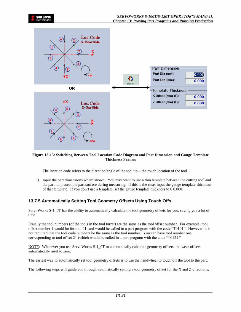
SERVOWORKS S-100T/S-120T OPERATOR’S MANUAL
Chapter 13: Proving Part Programs and Running Production
_____________________________________________________________________________________
13-21
Figure 13-15: Switching Between Tool Location Code Diagram and Part Dimension and Gauge Template
Thickness Frames
The location code refers to the direction/angle of the tool tip – the rouch location of the tool.
3) Input the part dimensions where shown. You may want to use a thin template between the cutting tool and
the part, to protect the part surface during measuring. If this is the case, input the gauge template thickness
of that template. If you don’t use a template, set the gauge template thickness to 0 0.000.
13.7.5 Automatically Setting Tool Geometry Offsets Using Touch Offs
ServoWorks S-1_0T has the ability to automatically calculate the tool geometry offsets for you, saving you a lot of
time.
Usually the tool numbers (of the tools in the tool turret) are the same as the tool offset number. For example, tool
offset number 1 would be for tool #1, and would be called in a part program with the code “T0101.” However, it is
not required that the tool code numbers be the same as the tool number. You can have tool number one
corresponding to tool offset 21 (which would be called in a part program with the code “T0121.”
NOTE: Whenever you use ServoWorks S-1_0T to automatically calculate geometry offsets, the wear offsets
automatically reset to zero.
The easiest way to automatically set tool geometry offsets is to use the handwheel to touch off the tool to the part.
The following steps will guide you through automatically setting a tool geometry offset for the X and Z directions:
OR

SERVOWORKS S-100T/S-120T OPERATOR’S MANUAL
Chapter 13: Proving Part Programs and Running Production
_____________________________________________________________________________________
13-22
13.7.5.1 Starting the Process of Setting Tool Geometry Offsets
1) If you haven’t already done a homing operation, press the button on the bottom toolbar, then
press the button on the bottom toolbar to set all axes to their home positions. Press the
button to return to Main Mode (the button should now be enabled).
2) Make sure the spindle is stopped. If it is not, press the button on the bottom toolbar of
ServoWorks S-1_0T main program window. You will then be in Spindle Mode. To stop the spindle
rotation, press the button on the right side of the bottom toolbar.
3) Make sure the collet is open. If the collet is closed, open it by pushing the “COLLET” button on the
operator’s panel.
4) Insert a raw material bar into your lathe. Then pull the bar out to the proper length (part length plus some
allowance in the Z direction for skim-cutting).
5) Close the collet by pushing the “COLLET” button on the operator’s panel. Now you have set up the tool
offset with respect to the workpiece zero point.
6) Press the button on the right toolbar of ServoWorks S-1_0T screen to get into Offset Mode.
You will see the window shown in Figure 14-13.
13.7.5.2 Selecting the Tool Offset
1) To select the tool offset you want to calculate, click on (select) any text box for that tool offset number.
For example, to enable Tool Offset #1, click on (select) any of the text boxes in Tool Offset #1.
2) Input the proper tool location codes for each tool offset number, based on tool direction / location of tool
tip (angle of tool nose). (If Tool #1 has a direction of 3 – see Figure 14-15 – then its tool code would be 3.)
13.7.5.3 Starting the Spindle Rotation
1) Press the button on the bottom toolbar to get to the second screen, shown in Figure 14-14.
2) Press the button or the button on the bottom toolbar to put the cursor in the input box
of “Spindle Turning Speed.” Type in the desired turning speed (for example, 1,000 RPMs).
NOTE: If you have a mouse, you can click on the “Spindle Turning Speed” text box, and type in it
directly.
3) Press the button on the bottom toolbar to select either “CW” (M03) or “CCW” (M04). Spindle
direction should match the tool direction, or the way the tool is mounted.

SERVOWORKS S-100T/S-120T OPERATOR’S MANUAL
Chapter 13: Proving Part Programs and Running Production
_____________________________________________________________________________________
13-23
NOTE: If you have a mouse, you can click on the preferred direction directly.
4) Press the button to start the spindle rotation. This button will then appear highlighted
( ).
NOTE: If you have a mouse, you can click on the button directly.
13.7.5.4 Turning on the HandWheel and Touching Off the Z and X Axes
1) Press the button on the bottom toolbar to turn the handwheel on. This button will then appear
highlighted ( ), to indicate that HandWheel Mode is enabled.
NOTE: If HandWheel Mode is already enabled, and the button is already highlighted
( ), you don’t need to press the button again.
2) If the HandWheel Axis Selection Switch on the HW-100 HandWheel (or other handwheel) is set to “OFF,”
turn it to one of the axes to turn the handwheel on.
3) Specify the Z axis by turning the Axis Selection Switch on the HW-100 HandWheel (see Figure 12-1) to
“Z” to select axis Z.
4) Use the Multiplier Selection Switch on the HW-100 HandWheel, (see Figure 12-1) to select one of three
multipliers:
“1” indicates a multiplier of “1” which will be applied to the handwheel or incremental jog machine
unit. If the machine unit is 0.001 mm and the multiplier is “1,” then each click of the HandWheel Dial
produces a movement of 0.001 mm.
“10” indicates a multiplier of “10” which will be applied to the handwheel or incremental jog machine
unit. If the machine unit is 0.001 mm and the multiplier is “10,” then each click of the HandWheel
Dial produces a movement of 0.01 mm.
“100” indicates a multiplier of “100” which will be applied to the handwheel or incremental jog
machine unit. If the machine unit is 0.001 mm and the multiplier is “100,” then each click of the
HandWheel Dial produces a movement of 0.10 mm.
5) Do a skim cut on the Z axis. A Z skim-cut is face cutting, which is used to measure the Z offset.

SERVOWORKS S-100T/S-120T OPERATOR’S MANUAL
Chapter 13: Proving Part Programs and Running Production
_____________________________________________________________________________________
13-24
Figure 13-16: Touching Off to Set the Z Axis Geometry Offset
NOTE: After the skim cut is done, DO NOT MOVE THE Z AXIS.
6) Now specify the X axis by turning the Axis Selection Switch on the HW-100 HandWheel (see Figure 12-1)
to “X,” or use the on the bottom toolbar to select axis X. Then retract the X axis to a safe
position.
7) Press the button to get to the first screen in Offset Mode.
8) Specify the Z axis again by turning the Axis Selection Switch on the HW-100 HandWheel (see Figure
12-1) to “Z.”
9) Press the button to have the Z geometry offset internally calculated. You will see that the Z
Geometry Offset data value is updated, and the Z Wear Offset data value is set to zero, for the tool offset
number you specified in Section 14.7.5.2: Selecting the Tool Offset.
10) Press the button on the bottom toolbar in order to save your changes. This saves your changes
into a registry file in the operating system.
11) Press the button on the bottom toolbar to get to the second screen, shown in Figure 14-14.
X
Z
Optional thin template between the cutting tool
and the part, to protect the part’s surface
Be careful: if you leave Offset Mode without pressing the button, all of
your changes will be lost, and you may or may not realize that your changes have not
been saved.
CAUTION !

SERVOWORKS S-100T/S-120T OPERATOR’S MANUAL
Chapter 13: Proving Part Programs and Running Production
_____________________________________________________________________________________
13-25
12) Specify the X axis by turning the Axis Selection Switch on the HW-100 HandWheel (see Figure 12-1) to
“X,” or use the on the bottom toolbar to select axis X.
13) Do a skim cut on the X axis. An X skim-cut is turn cutting, which is used to measure the X offset.
Figure 13-17: Touching Off to Set the X Axis Geometry Offset
NOTE: After the skim cut is done, do not move the X axis.
14) Now specify the Z axis by turning the Axis Selection Switch on the HW-100 HandWheel (see Figure 12-1)
to “Z,” or use the on the bottom toolbar to select axis Z. Then retract the Z axis to a safe
position.
13.7.5.5 Finishing the Setting of the Tool Geometry Offsets
1) Stop the spindle rotation by pressing the button on the bottom toolbar. This button will then
appear gray ( ).
2) Press the button to get to the first screen in Offset Mode.
3) Press the button to on the bottom toolbar to make the “Part Dimension” and “Gauge Template
Thickness” frames appear. (The button toggles you between the two views shown in Figure 14-
15.)
X
Z
Optional thin template between the cutting tool
and the part, to protect the part’s surface

SERVOWORKS S-100T/S-120T OPERATOR’S MANUAL
Chapter 13: Proving Part Programs and Running Production
_____________________________________________________________________________________
13-26
4) Measure the part diameter (in inches) and type that data in the text frame labeled “Part Dia:”.
5) Specify the X axis by turning the Axis Selection Switch on the HW-100 HandWheel (see Figure 12-1) to
“X,” or use the on the bottom toolbar to select axis X.
6) Press the button to have the X geometry offset internally calculated based on the X axis position
and the part diameter. You will see that the X Geometry Offset data value is updated, and the X Wear
Offset data value is set to zero, for the tool offset number you specified in Section 14.7.5.2: Selecting the
Tool Offset.
NOTE: If the “program measuring” parameter is set to “diameter,” the X offset data is shown as a diameter
value. If the “program measuring” parameter is set to “radius,” the X offset data is shown as a radius value.
7) Press the button on the bottom toolbar in order to save your changes. This saves your changes
into a registry file in the operating system.
You must repeat the steps in Sections 14.7.5.2 through 14.7.5.5 for each tool / tool offset. However, since the
workpiece zero point Z and the turning surface X have been set, you should do touch-offs instead of skim cutting for
the X and Z axes. You will need to type the corresponding template thickness for each axis.
NOTE: The X offset of the gauge template should be radius (thickness) value.
13.7.6 Automatically Setting Tool Geometry Offsets Using Tool Measuring Sensors
In lieu of moving the tool to touch off the part (as described in Section 14.7.5: Automatically Setting Tool Geometry
Offsets Using Touch Offs), you would use a tool measurer, and touch the part to the tool measurer sensors. The tool
offset values are filled in automatically through PLC when the tool touches the measuring sensors.
Press the button on the bottom toolbar to use the Auto Measurer feature while in Offset Mode.
13.7.7 Calculating Tool Wear Offsets
The easiest way to calculate tool wear offsets is to measure the parts your lathe is producing. The more often you
recalculate tool wear offsets, the more accurate the parts you will cut.
For example: If the program was designed to create a part with a diameter of 1.000”, and it’s now producing parts
that have a diameter of 1.002”, it’s off by 0.002” in diameter. Therefore, the tool wear offset is half of this
difference, or 0.001”, for radius programming (or 0.002” for diameter programming).

SERVOWORKS S-100T/S-120T OPERATOR’S MANUAL
Chapter 13: Proving Part Programs and Running Production
_____________________________________________________________________________________
13-27
Figure 13-18: Calculating Tool Wear Offsets: Top View of a Lathe
13.7.8 Exiting Offset Mode
To exit Offset Mode (and get back to whatever mode you were in before pressing the button), press the
key on your panel PC, or press the button again.
13.8 Setting the External Zero Offset and Workpiece Zero Point Offsets
13.8.1 What Is An External Zero Offset?
The external zero offset is the offset value of the external workpiece coordinate system used for shifting the
machine origin, as shown in the following figure:
Tool Design diameter
Diameter of part currently being produced
1.00
0”
1.00
2”
0.00
1”
X
Z
Z
X
Machine Origin (0.0000, 0.0000)
Workpiece Coordinate System #1
Workpiece Coordinate
System #4
Workpiece Coordinate
System #5
Workpiece Coordinate
System #6
Workpiece Coordinate System #2
Workpiece Coordinate System #3
G54
G58
G56 G55
G57 G59
Origin of external workpiece coordinate system

SERVOWORKS S-100T/S-120T OPERATOR’S MANUAL
Chapter 13: Proving Part Programs and Running Production
_____________________________________________________________________________________
13-28
Figure 13-19: The External Workpiece Coordinate System
13.8.2 What Are Workpiece Zero Point Offsets (Workpiece Coordinates)?
Workpiece zero point offsets (workpiece coordinates) allow you to assign multiple part origins in one program, to
produce a number of identical workpieces from one part program. You will need to set your workpiece coordinates
before you run production. You should change your workpiece coordinates every time you open a new part program
to run.
The workpiece coordinate systems are selectable with G codes G54 – G59 (which are called from within the part
programs with no parameters – the parameters, or arguments, are taken from the settings in the Coordinates/Counter
Mode Window).
13.8.3 Accessing the External Zero Offset and the Work Point Coordinates
To access the work point parameters, you must get into Coordinates/Counter Mode (a sub mode in ServoWorks
S-1_0T). To get into Coordinates/Counter Mode, press the button on the right toolbar of ServoWorks
S-1_0T screen. You will see the shown in Figure 14-20.
NOTE: If the button is disabled (appears as ), it’s probably because you have not set the
home position for your axes. You must set the home position – see Section 3.4: Performing a Homing Operation.
[Press the button on the bottom toolbar, then press the button on the bottom toolbar to set all
axes to their home positions at the same time. Press the button to return to Main Mode. The
button should now be enabled for you to select it.]

SERVOWORKS S-100T/S-120T OPERATOR’S MANUAL
Chapter 13: Proving Part Programs and Running Production
_____________________________________________________________________________________
13-29
Figure 13-20: The Coordinates/Counter Mode Window
You may need to press the to put the focus on the “Workpiece Coordinate System” frame. (The
button toggles you between the “Workpiece Coordinate System” frame and the “Part Counter” frame.)
If you don’t want to use the external zero offset (you don’t need an external workpiece coordinate system), make
sure the values in these text boxes are “0.”

SERVOWORKS S-100T/S-120T OPERATOR’S MANUAL
Chapter 13: Proving Part Programs and Running Production
_____________________________________________________________________________________
13-30
13.8.4 Selecting and Changing the Input for the Work Point Parameters
13.8.4.1 Moving Between the Text Boxes
Moving between the text boxes is actually very simple. The selected text box is shown with a different color
background than the other text boxes. To move up and down between text boxes, press the and
buttons on the bottom toolbar to move in the desired direction. To move between the text boxes for the X
and Z axes, press the button.
NOTE: If you have a mouse, you can click on the text box you want to select.
13.8.4.2 Changing Values in the Text Boxes
Once you have selected the text box whose value is to be changed, press the and buttons on
the bottom toolbar to decrease and increase the value in the chosen text box. Holding down the function key for one
of these buttons causes the value to change very quickly. Quick, individual key presses cause the value to decrease
or increase by a value of “1” for each key press.
NOTE: If you have a mouse, you can type in the new value you want to input.
13.8.4.3 Saving Your Changes
In order to save your changes, you must press the button on the bottom toolbar. This saves your changes
into a registry file in the operating system.
13.8.4.4 Setting the Workpiece Coordinates Back to the Default Settings
To reset the tool offsets back to their default settings of 0.000, press the button.
Be careful: if you leave the Coordinates/Counter Mode without pressing the
button, all of your changes will be lost, and you may or may not realize
that your changes have not been saved.
CAUTION !

SERVOWORKS S-100T/S-120T OPERATOR’S MANUAL
Chapter 13: Proving Part Programs and Running Production
_____________________________________________________________________________________
13-31
13.8.4.5 Exiting Coordinates/Counter Mode
To exit Coordinates/Counter Mode (and get back to whatever mode you were in before pressing the
button), press the key, or press the button again.
13.9 Setting the Part Counter Options
13.9.1 Accessing the Part Counter Frames
To access the part counter options, you must get into Coordinates/Counter Mode (a sub mode in ServoWorks
S-1_0T). To get into Coordinates/Counter Mode, press the button on the right toolbar of ServoWorks
S-1_0T screen. You will see the shown in Figure 14-20.
NOTE: If the button is disabled (appears as ), it’s probably because you have not set the
home position for your axes. You must set the home position – see Section 3.4: Performing a Homing Operation.
[Press the button on the bottom toolbar, then press the button on the bottom toolbar to set all
four axes to their home positions at the same time. Press the button to return to Main Mode. The
button should now be enabled for you to select it.]
You may need to press the to put the focus on the “Part Counter” frame. (The button toggles
you between the “Workpiece Coordinate System” frame and the “Part Counter” frame.)
13.9.2 Specifying Counter Options
You should specify a number for the part counter to count from. You can also activate an M code counter, instead
of a part code counter. You can count how many times the M02 code is executed, or the M30 code is executed, or
you can specify some other M code to be counted.
Figure 13-21: Counting At Frame (M Code Counter Options)

SERVOWORKS S-100T/S-120T OPERATOR’S MANUAL
Chapter 13: Proving Part Programs and Running Production
_____________________________________________________________________________________
13-32
In order to save your changes, you must press the button on the bottom toolbar. This saves your changes
into a registry file in the operating system.
13.9.3 Exiting Counter/Coordinates Mode
To exit Coordinates/Counter Mode (and get back to whatever mode you were in before pressing the
button), press the key, or press the button again.
13.10 Running Production
13.10.1 Production Run Checklist
Before you start a production run, you should make sure of the following:
Your part program file is loaded, and you have proved the program
You have set the operation support function switches (Dry Run, Optional Skip, Optional Stop, Single Block
and MST Codes Lock)
You have set the feed override percentage and rapid override percentage to the desired settings
You have set the general parameters (unit of measurement, program measuring) in Configuration Mode
You have set your Auto Plot parameters (in Configuration Mode) to the correct part size for the part
program you will be running, so that your plot displays correctly
You have set your tool offsets
You have set your work coordinates
You have set your part counters
Be careful: if you leave the Coordinates/Counter Mode without pressing the
button, all of your changes will be lost, and you may or may not realize
that your changes have not been saved.
CAUTION !

SERVOWORKS S-100T/S-120T OPERATOR’S MANUAL
Chapter 13: Proving Part Programs and Running Production
_____________________________________________________________________________________
13-33
13.10.2 Executing a Part Program
To start the execution of a part program, press the button on the bottom toolbar. During execution, the
line of code being executed is highlighted and appears with an asterisk beside it.
To stop the part program execution, press the button on the bottom toolbar. The operation will be
suspended immediately.
When you have stopped the execution of a part program, you can continue from where you left off by pressing the
button again. The program will start again from where it left off (the current, highlighted block).
Or, you can restart the program from the beginning, which is explained in the next section.
13.10.3 Rewinding or Fast Forwarding a Part Program
At any time, you can restart a part program from the beginning of the program or you can rewind or fast forward to
begin execution from some specified block number. Restarting the program also resets the modal codes to the
default modal codes, cancels the local coordinate system, and resets the Cycle Time to 0:00:00.
To restart the program from the beginning (the first line of code):
1) Press the button on the bottom toolbar. The buttons on the bottom toolbar will change.
2) Press the button. The “Program FF/BW” frame will show the “Rewind Program” selected, as
shown in the following figure:
Figure 13-22: Program FF/BW Frame (1 of 2)
3) Press the button on the bottom toolbar. This will set the first line of your program as the current
line (the line that will execute once you resume operations). This also resets the Cycle Time to 0:00:00.
4) To restart the program, press the button on the bottom toolbar.
To start the program from a specific line of code (either rewinding back to a specific line of code or fast forwarding
ahead to a specific line of code):

SERVOWORKS S-100T/S-120T OPERATOR’S MANUAL
Chapter 13: Proving Part Programs and Running Production
_____________________________________________________________________________________
13-34
1) Press the button on the bottom toolbar. The buttons on the bottom toolbar will change.
2) Press the button. The “Program FF/BW” frame will show the “Go To Block No.” selected, as
shown in the following figure:
Figure 13-23: Program FF/BW Frame (2 of 2)
3) Type in a block number in the text box in the “Program FF/BW” frame.
4) Press the button on the bottom toolbar. This will set the first line of your program to be the line
you specified in the “Program FF/BW” frame (the line that will execute once you resume operations). This
also resets the Cycle Time to 0:00:00.
NOTE: If you type in a block number that doesn’t exist, you will get the following error message:
Figure 13-24: ALARM MESSAGE: Alarm Code 52
You will need to press the button to acknowledge and erase this message.

SERVOWORKS S-100T/S-120T OPERATOR’S MANUAL
Chapter 13: Proving Part Programs and Running Production
_____________________________________________________________________________________
13-35
13.11 Exiting Auto Mode
To exit Auto Mode, either press the key or press the button on the bottom toolbar. If you had used
Auto Mode to run a part program file, you will see the following dialog box appear:
Figure 13-25: Confirmation Dialog Box for Exiting Auto Mode
Press the button on the bottom toolbar to confirm that you want to exit Auto Mode.
NOTE: If you have changed your mind about exiting Auto Mode, press the button on the bottom
toolbar.

SERVOWORKS S-100T/S-120T OPERATOR’S MANUAL
Chapter 14: Exiting ServoWorks S-100T/S-120T
_____________________________________________________________________________________
14-1
Chapter 14: Exiting ServoWorks S-100T/S-120T
14.1 Exiting from Main Mode
To exit ServoWorks S-1_0T from Main Mode, you must press the key on your panel PC (if you are using a
panel PC) or the “Esc” key on your keyboard (if you are using a keyboard).
Figure 14-1: Exiting from Main Mode
When you give the command to exit, a dialog box will appear, as shown in the following figure.
Figure 14-2: Dialog Box to Confirm Exiting ServoWorks S-1_0T
Press the button to exit, or press the button if you decide that you don’t want to exit.
NOTE: If you have selected “Quit S-1_0T and shut down PC” from the “General” screen of Configuration Mode,
exiting ServoWorks S-1_0T will also invoke the shut down process for your PC.
MAIN MODE
EXIT

SERVOWORKS S-100T/S-120T OPERATOR’S MANUAL
Chapter 14: Exiting ServoWorks S-100T/S-120T
_____________________________________________________________________________________
14-2
14.2 Exiting from an Operational Mode
If you are in an operational mode, you should stop all motion, then press the button to get to Main Mode,
and then press the key on your panel PC (if you are using a panel PC) or the “Esc” key on your keyboard (if
you are using a keyboard) to exit.
Alternatively, if you are in an operational mode, you can press the key on your panel PC twice (if you are
using a panel PC) or the “Esc” key on your keyboard twice (if you are using a keyboard). The first press of the
“Esc” key takes you to Main Mode, the second press causes ServoWorks S-1_0T to exit.
Figure 14-3: Exiting from an Operational Mode
When you give the command to exit, a dialog box will appear, as shown in Figure 15-2. Press the button
to exit, or press the button if you decide that you don’t want to exit.
NOTE: If you have selected “Quit S-1_0T and shut down PC” from the “General” screen of Configuration Mode,
exiting ServoWorks S-1_0T will also invoke the shut down process for your PC.
MAIN MODE
Operational Mode
EXIT
OR
MAIN MODE
Operational Mode
EXIT

SERVOWORKS S-100T/S-120T OPERATOR’S MANUAL
Chapter 14: Exiting ServoWorks S-100T/S-120T
_____________________________________________________________________________________
14-3
14.3 Exiting from a Sub Mode
14.3.1 If You Entered the Sub Mode From Main Mode
You can press the button or press the sub button again to get to Main Mode, and then press the key
on your panel PC (if you are using a panel PC) or the “Esc” key on your keyboard (if you are using a keyboard) to
exit ServoWorks S-1_0T.
Alternatively, you can press the key on your panel PC twice (if you are using a panel PC) or the “Esc” key on
your keyboard twice (if you are using a keyboard). The first press of the “Esc” key takes you to Main Mode, the
second press causes ServoWorks S-1_0T to exit.
Figure 14-4: Exiting from a Sub Mode – Option #1
When you give the command to exit, a dialog box will appear, as shown in Figure 15-2. Press the button
to exit, or press the button if you decide that you don’t want to exit.
NOTE: If you have selected “Quit S-1_0T and shut down PC” from the “General” screen of Configuration Mode,
exiting ServoWorks S-1_0T will also invoke the shut down process for your PC.
MAIN MODE
Sub Mode
EXIT
OR
MAIN MODE
Sub Mode
EXIT
MAIN MODE
Sub Mode
EXIT
OR

SERVOWORKS S-100T/S-120T OPERATOR’S MANUAL
Chapter 14: Exiting ServoWorks S-100T/S-120T
_____________________________________________________________________________________
14-4
14.3.2 If You Entered the Sub Mode From An Operational Mode
You must make sure no motion is occurring, then press the button to get to Main Mode, and then press the
key on your panel PC (if you are using a panel PC) or the “Esc” key on your keyboard (if you are using a
keyboard) to exit ServoWorks S-1_0T.
Alternatively, you can press the key on your panel PC three times (if you are using a panel PC) or the “Esc”
key on your keyboard three times (if you are using a keyboard). The first press of the “Esc” key takes you to the
operational mode from which you entered the sub mode; the second press of the “Esc” key takes you to Main Mode;
and the third press causes ServoWorks S-1_0T to exit.
Figure 14-5: Exiting from a Sub Mode – Option #2
When you give the command to exit, a dialog box will appear, as shown in Figure 15-2. Press the button
to exit, or press the button if you decide that you don’t want to exit.
NOTE: If you have selected “Quit S-1_0T and shut down PC” from the “General” screen of Configuration Mode,
exiting ServoWorks S-1_0T will also invoke the shut down process for your PC.
MAIN MODE
Sub Mode
EXIT OR
MAIN MODE
Operational Mode
EXIT
Sub Mode

SERVOWORKS S-100T/S-120T OPERATOR’S MANUAL
Chapter 15: Troubleshooting
_____________________________________________________________________________________
15-1
Chapter 15: Troubleshooting
While using ServoWorks S-1_0T, it is possible that you may come across some problems. Several common
scenarios are listed here, with tips on how to solve the difficulty.
15.1 Resetting ServoWorks S-100T/S-120T If E-STOP Is Activated
Figure 15-1: Window Showing Alarms When E-STOP Has Been Activated
Use the button if the computer behaves unexpectedly. The button does the following:
Resets all variables back to their default values.
Clears memory, clears internal control flags or status, clears alarms (and alarm signals).
If the spindle is running before you press the button, then the spindle will be stopped.

SERVOWORKS S-100T/S-120T OPERATOR’S MANUAL
Chapter 15: Troubleshooting
_____________________________________________________________________________________
15-2
All the servo / spindle drives will be off, regardless of whether or not they were on before pressing the
button.
Then you need to turn each servo drive on, by clicking the “ON” button ( ) for each drive, or clicking on
any or all of the buttons on the bottom toolbar:
Figure 15-2: Window Showing Servo Drive Controls

SERVOWORKS S-100T/S-120T OPERATOR’S MANUAL
Chapter 15: Troubleshooting
_____________________________________________________________________________________
15-3
15.2 Using the Flight Recorder for Debugging
ServoWorks S-1_0T provides a flight recorder function to use in debugging, and determining why an Emergency
Stop has occurred.
When an Emergency Stop is triggered, ServoWorks S-1_0T will save the last 20 seconds of data (prior to the
Emergency Stop) to the hard drive at C:\Program Files\SoftServo\ServoWorks S-1_0T\data\default, as shown:
Figure 15-3: Flight Recorder Files in Default Data Folder
The data is saved in seven files, for the last 20 seconds of information related to:
Analog to Digital Conversion (ADC)
Position command data
Digital to Analog Conversion (DAC)
Position error
Handwheel data
The Interrupt Service Routine (ISR)
Position feedback (actual position)
For an ISR of 1 millisecond (like the VersioBus interface system), this results in 20,000 values for each data type.
These files can be sent to Soft Servo Systems, Inc. for debugging.
A sample data file for the ISR follows:

SERVOWORKS S-100T/S-120T OPERATOR’S MANUAL
Chapter 15: Troubleshooting
_____________________________________________________________________________________
15-4
Figure 15-4: Sample default_ISR.dat File
15.3 If the Homing Operation Does Not Seem to Work….
If Home Mode does not seem to work (does not set the axes to their home positions), it could be that the “position
loop gain” is too small, and needs to be reset.

SERVOWORKS S-100T/S-120T OPERATOR’S MANUAL
Chapter 16: Alarms
_____________________________________________________________________________________
16-1
Chapter 16: Alarms
16.1 Alarms
The S-1_0T application displays an alarm when it detects certain problems. A sample alarm is shown below:
Figure 16-1: ALARM MESSAGE
16.2 List of Alarms
The following is a list of the alarms that may appear in the S-1_0T application. In addition to these alarms, custom
alarms may be programmed using the PLC.
Alarm Code 01: Over-travel Software Limit X +
Alarm Code 02: Over-travel Software Limit C + or Y +
Alarm Code 03: Over-travel Software Limit Z +
Alarm Code 04: Over-travel Software Limit C +
Alarm Code 05: Over-travel Software Limit X -
Alarm Code 06: Over-travel Software Limit C - or Y -
Alarm Code 07: Over-travel Software Limit Z -
Alarm Code 08: Over-travel Software Limit C -
Alarm Code 09: Over-travel Hardware Limit X +
Alarm Code 10: Over-travel Hardware Limit C + or Y +
Alarm Code 11: Over-travel Hardware Limit Z +
Alarm Code 12: Over-travel Hardware Limit C +
Alarm Code 13: Over-travel Hardware Limit X -
Alarm Code 14: Over-travel Hardware Limit C - or Y -
Alarm Code 15: Over-travel Hardware Limit Z -
Alarm Code 16: Over-travel Hardware Limit C -
Alarm Code 17: M: Timeout
Alarm Code 18: S: Timeout
Alarm Code 19: T: Timeout
Alarm Code 20: B: Timeout
Alarm Code 21: E-Stop: X is over Stopped-Limit
Alarm Code 22: E-Stop: C is over Stopped-Limit
Alarm Code 23: E-Stop: Z is over Stopped-Limit
Alarm Code 24: E-Stop: C is over Stopped-Limit
Alarm Code 25: E-Stop: X is over Moving-Limit
Alarm Code 26: E-Stop: C is over Moving-Limit
Alarm Code 27: E-Stop: Z is over Moving-Limit
Alarm Code 28: E-Stop: C is over Moving-Limit
Alarm Code 29: X Homing: Timeout
Alarm Code 30: C Homing: Timeout

SERVOWORKS S-100T/S-120T OPERATOR’S MANUAL
Chapter 16: Alarms
_____________________________________________________________________________________
16-2
Alarm Code 31: Z Homing: Timeout
Alarm Code 32: C Homing: Timeout
Alarm Code 33: End of Smoothing: Timeout
Alarm Code 34: In-Position Check: Timeout
Alarm Code 35: Loss of Communication: Among PC, FP-60 and DC-120
Alarm Code 36: Actual Spindle Speed: Not In-Range
Alarm Code 37: Spindle Speed Command: Zero
Alarm Code 38: M: Invalid Data
Alarm Code 39: S: Invalid Data
Alarm Code 40: T: Invalid Data
Alarm Code 41: B: Invalid Data
Alarm Code 42: Cutting Feedrate: Too Fast
Alarm Code 43: Cutting Feedrate: Zero Command
Alarm Code 44: Enter Chuck Barrier
Alarm Code 45: Enter Tailstock Barrier
Alarm Code 46: Program Error
Alarm Code 47: Not At 1st Home Position
Alarm Code 48: Not At 2nd Home Position
Alarm Code 49: Not At 3rd Home Position
Alarm Code 50: Not At 4th Home Position
Alarm Code 51: C Axis is not enabled yet
Alarm Code 52: Block Number is not found
Alarm Code 53: Actual Spindle Speed: Zero
Alarm Code 60: X Axis
Alarm Code 62: Z Axis
Alarm Code 63: Spindle Axis
Alarm Code 302: G02 Format Error
Alarm Code 303: G03 Format Error
Alarm Code 310: G10 Format Error
Alarm Code 327: G27 Format Error
Alarm Code 328: G28 Format Error
Alarm Code 329: G29 Format Error
Alarm Code 330: G30 Format Error
Alarm Code 340: G40 Format Error
Alarm Code 341: G41 Format Error
Alarm Code 342: G42 Format Error
Alarm Code 370: G70 Format Error
Alarm Code 371: G71 Format Error
Alarm Code 372: G72 Format Error
Alarm Code 373: G73 Format Error
Alarm Code 374: G74 Format Error
Alarm Code 375: G75 Format Error
Alarm Code 376: G76 Format Error
Alarm Code 383: G83 Format Error
Alarm Code 384: G84 Format Error
Alarm Code 385: G85 Format Error
Alarm Code 387: G87 Format Error
Alarm Code 388: G88 Format Error
Alarm Code 389: G89 Format Error
Alarm Code 390: G90 Format Error
Alarm Code 392: G92 Format Error
Alarm Code 394: G94 Format Error
Alarm Code 701: G76 Feed Mode Error
Alarm Code 702: G83 Feed Mode Error
Alarm Code 703: G84 Feed Mode Error
Alarm Code 704: G85 Feed Mode Error

SERVOWORKS S-100T/S-120T OPERATOR’S MANUAL
Chapter 16: Alarms
_____________________________________________________________________________________
16-3
Alarm Code 705: G87 Feed Mode Error
Alarm Code 706: G88 Feed Mode Error
Alarm Code 707: G89 Feed Mode Error
Alarm Code 708: G92 Feed Mode Error
Alarm Code 709: Circular Interpolation End Point Invalid
Alarm Code 751: G71 Not Monotone
Alarm Code 752: G72 Not Monotone
Alarm Code 800: Canned Format Error
Alarm Code 801: TNRC Format Error
Alarm Code 802: TNRC Calculation Error
Alarm Code 803: MSTB Error
Alarm Code 804: Chamber Error

SERVOWORKS S-100T/S-120T OPERATOR’S MANUAL
Index
_____________________________________________________________________________________
IV
Index
.
.reg files, 3-37
/
/, 13-6
\
\, 13-6
<
<< button, 3-5
>
>> button, 3-5
0
0 signal, 3-29, 3-31, 4-6, 4-7
1
1 signal, 3-29, 3-31, 4-6, 4-7
1st Spindle Gear frame, 3-26
2
2nd Spindle Gear frame, 3-26
3
3rd Spindle Gear frame, 3-26
4
4th Spindle Gear frame, 3-26
A
absolute position, 4-4
accessing the color parameters, 3-42
accessing the external zero offset, 13-28
accessing the part counter frames, 13-31
accessing the tool offsets, 13-17
accessing the work point coordinates, 13-28
actual position, 4-4
actual tool position, 13-14
adapter board, 1-3
ADC, 15-3
Alarm Code 52, 13-34
alarms, 16-1
ALL button, 2-10, 10-1, 13-1, 13-17, 13-22, 13-28,
13-31
all-axes simultaneous interpolation, 1-1
APPLY button, 3-7, 3-52, 3-53, 13-20, 13-24, 13-26,
13-30, 13-32
area in, 3-15
area out, 3-15
AUTO button, 13-1
Auto Mode, 2-3, 12-1, 13-1
Auto Mode Window
for opening a file, 13-3
showing all three bottom toolbars, 13-2
with Part Program file executing, 13-5
AUTO MSR button, 13-26
auto plot parameters, 3-2, 3-4, 3-41
AUTO PLT button, 3-4, 3-41
automatic control, 1-2
automatic plotting, 3-41
Automatic Start option, 4-10
automatically setting tool offsets
using tool measuring sensors, 13-26
using touch offs, 13-21
average cutting time per part, 4-4
AXIS button, 3-5, 11-4, 13-24, 13-25, 13-26, 13-30
Axis frame, 7-3, 8-4, 9-3, 11-4
Axis Selection Switch, 11-1, 11-4, 13-23, 13-24, 13-
25, 13-26
Axis Selection Switch settings for the HW-100, 11-5
AXIS X button, 2-9
B
B in Lock Status Indicator, 4-2
BACK button, 3-14, 3-16, 12-3, 13-1, 13-3, 13-20,
13-24, 13-25
backing up part program files, 12-9
backlash compensation, 3-20
Backlash Compensation frame, 3-20
backup file, 3-39
Backup Prompt Window in Editor Mode, 12-10
BKP FILE button, 12-10
block delete code, 13-6
blocks of code
renumbering, 12-7
Bottom Toolbar, 2-2
Button Background, 3-45
button display, 3-45, 3-46
Button On Status, 3-45
buttons
background, 3-45
on status, 3-45
C
C axis, 1-1, 6-1

SERVOWORKS S-100T/S-120T OPERATOR’S MANUAL
Index
_____________________________________________________________________________________
V
calculating tool wear offsets, 13-26, 13-27
calibrating the lathe, 3-11
CANCEL button, 3-38, 3-39, 12-9, 13-4, 13-35, 14-1,
14-2, 14-3, 14-4
Center of Chuck Face frame, 3-15
chamfer angle, 3-10
changing a part program, 12-1
changing color parameters, 3-51
changing I/O signals, 3-29, 3-31
changing the orientation of a plot, 4-11
changing the scale of a plot, 4-12
changing values in text boxes
in Configuration Mode, 3-6
in Coordinates/Counter Mode, 13-30
in Offset Mode, 13-20
changing your password, 3-10
checklist for running production, 13-32
CHG – button, 3-6, 3-51, 3-52, 3-53, 13-30
CHG + button, 3-6, 3-51, 3-52, 3-53, 13-30
CHG SEL button, 10-3, 10-4, 12-3, 12-7
choosing a drive when opening a file, 3-37, 12-5, 12-
8, 12-10, 12-11, 12-12, 12-13, 13-3
choosing from among options in a frame, 3-6
chuck barrier diagram, 3-16
Chuck Barrier frame, 3-16
CLEAR button, 4-13
clearing a plot, 4-13
clearing the relative positions, 4-4
CLR/WR button, 10-3, 10-4
CNC part programming, 10-1, 13-1
COLOR button, 3-5, 3-42, 3-52
color parameters, 3-2, 3-5, 3-42
accessing, 3-42
default, 3-42, 3-54
selecting and changing, 3-51
Color Parameters Display Area, 3-42
Color Selection frame, 3-42, 3-52
Command Log, 10-3, 10-4
command position, 4-3
CONFIG button, 3-2, 3-5, 11-2
Configuration Mode, 2-3, 3-2, 3-51
Configuration Mode Window, 3-3
configuring system parameters, 3-1, 3-2
configuring the program parameters, 3-1
CONT button, 12-10, 12-12, 12-13, 12-14
continuous jogging, 7-1
control modes, 2-3
display of current mode, 2-6, 2-7
flow charts, 2-5, 2-6
in ServoWorks S-1_0T, 2-2
navigating, 2-3
Control Type frame, 3-25
coordinate system, 2-8
Coordinates/Counter Mode, 13-28, 13-31
Coordinates/Counter Mode Window, 13-29
COPY button, 12-6
copying a registry file, 3-37, 3-38
copying text in a part program, 12-6
counter options, 13-31
Counting At frame, 13-31
creating a part program, 12-1, 12-4
creating a registry file, 3-37, 3-38
Custom, 8-2, 8-3
customizing your display, 3-42
Cutting – G01 pull-down menu, 3-53
cutting air, 13-13
Cutting frame, 3-17
cutting time, 4-4
Cycle Time, 3-41
resetting, 13-33
Cycle Time Indicator, 4-1, 4-2
D
DAC, 15-3
data display, 3-50, 3-51
Data Position Format frame, 3-40
data recording and plotting, 3-11, 3-19, 3-27
date and time, 4-4
DC-120, 3-29, 4-6
DC-120 button, 3-30
DC-120 I/O button, 4-9, 4-10
DC-120 I/O Settings Display Area, 3-30
DC-150, 3-29, 4-6
DC-150 button, 3-30
debugging, 15-3
DEFAULT button, 3-7, 3-54, 13-30
default M codes, 3-32
default modal codes, 13-33
default parameters, 2-1
default settings
of color parameters, 3-42, 3-54
of parameters, 3-7
of workpiece coordinates, 13-30
DEL FILE button, 12-12
Delete Prompt Window in Editor Mode, 12-13
deleting a plot, 4-13
deleting part program files, 12-12
desktop icon, 2-1
diagram of the HW-100 handwheel, 11-1
diagram of tool offsets, 13-15
diameter display, 3-9
difference between the Machine Lock and Interlock
switches, 13-12
DIRECT button, 6-2
Direction frame, 7-3, 8-4, 9-3
DIS – button, 8-3
DIS + button, 8-3
DIS SEL button, 8-2, 8-3
Dis To Go (Pulse), 8-3
Dis To Go (Pulse) frame, 8-3
disabled output commands, 13-9

SERVOWORKS S-100T/S-120T OPERATOR’S MANUAL
Index
_____________________________________________________________________________________
VI
disabling the handwheel, 3-24
display
buttons, 3-45, 3-46
data, 3-50, 3-51
G code, 3-49
interface, 3-44
plot, 3-47, 3-48
DISPLAY button, 3-4, 3-40
Display Compensation Data frame, 3-20
display customization, 3-42
display of current mode, 2-7
Display of Four Types of Position Data frame, 3-40
Display of Two Types of Position Data frame, 3-40
display parameters, 3-2, 3-4, 3-40
distance to go, 4-4, 8-1, 8-2
DN/CHG button, 12-4, 12-8
documentation, 1-1
DOWN button, 3-5, 3-31, 3-37, 3-38, 4-13, 10-3, 12-
5, 12-6, 12-9, 12-10, 12-11, 12-12, 12-13, 12-14,
13-4, 13-19, 13-30
DRIVE button, 3-37, 12-5, 12-9, 12-10, 12-11, 12-
12, 12-14, 13-4
DRN SPD – button, 13-13
DRN SPD + button, 13-13
DRY RUN button, 13-13
dry run speed, 13-13
dry run switch, 13-6, 13-13
duplicating parameter files, 3-37
E
EDIT button, 12-6
edit functions, 12-6
editing a part program, 12-1, 12-4, 12-6
EDITOR button, 12-1, 12-15
Editor Mode
using, 12-1
using the Editor, 12-6
Editor Mode Window, 12-2
for Opening a File, 12-5
Element pull-down menu, 3-51, 3-52
elements, 3-43
Emergency Stop, 15-3
Emergency Stop Button, 5-2, 11-1
is activated, 15-1
resetting, 5-2
enabling the handwheel, 3-24
encoder parameters, 3-11
Encoder Parameters frame, 3-25
END key, 12-6
Engine, 2-1
entering and executing commands in MDI Mode, 10-
3
escape key, 2-3, 2-4, 3-5, 3-54, 4-9, 4-10, 4-11, 4-13,
5-3, 5-4, 12-6, 12-9, 12-11, 12-12, 12-13, 12-15,
13-4, 13-10, 13-11, 13-27, 13-31, 13-32, 13-35,
14-1, 14-2, 14-3, 14-4
E-STOP is activated, 15-1
example frame, 3-6
with options, 3-6
executing a part program, 13-1, 13-33
exiting Editor Mode, 12-15
exiting from a sub mode, 14-3, 14-4
exiting from an operational mode, 14-2
exiting Offset Mode, 13-27
exiting Plot Mode, 4-13
exiting Screen Mode, 4-9
exiting ServoWorks S-100T/S-120T, 14-1
from a sub mode, 14-3
from an operational mode, 14-2
from Main Mode, 14-1
external workpiece coordinate system, 13-28
external zero offset, 13-27
Extra Home Positions frame, 3-23
F
F in Lock Status Indicator, 4-2
fast forwarding a part program, 13-33
feed override, 13-5
Feed Override % frame, 7-3
Feed Override (%) slider, 13-6
FEED SEL button, 7-2
FEEDRATE button, 3-4, 3-22
Feedrate frame, 8-2
Feedrate Indicator, 4-1, 4-2
feedrate load factor, 3-10
feedrate parameters, 3-1, 3-4, 3-22
Feedrate Parameters Display Area, 3-22
FILE LIST button, 3-38, 12-6, 12-9, 12-10, 12-11,
12-13, 12-14, 13-4
FILE NAME button, 12-9, 12-14
file names, 12-9
FIND button, 12-8
Find frame, 12-8
Find Tool, 12-3, 12-7, 12-8
finding text in a part program, 12-7
FIT button, 4-12
flight recorder, 15-3
flow chart for control modes, 2-5, 2-6
FOLDER button, 3-38, 12-5, 12-9, 12-10, 12-11, 12-
12, 12-14, 13-4
FP-104, 3-29, 4-5
FP-104 button, 3-30
FP-60, 3-29, 4-5
FP-60 button, 3-30
FP-60 I/O button, 4-8, 4-10
FP-60 I/O Settings Display Area, 3-29
FP-75, 3-29, 4-5
FP-75 button, 3-30
FP-80, 3-29, 4-5

SERVOWORKS S-100T/S-120T OPERATOR’S MANUAL
Index
_____________________________________________________________________________________
VII
FP-80 button, 3-30
FP-95, 3-29, 4-5
FP-95 button, 3-30
frame, 3-6
freezing a plot, 4-13
function keys, 1-3
using with shift keys, 1-5, 1-6, 1-7
G
G code
background, 3-49
display, 3-49
foreground, 3-49
on status, 3-49
G Code Background, 3-49
G code definitions, 10-3, 12-3
G code display, 3-49
G Code Foreground, 3-49
G Code On Status, 3-49
G code part programs, 1-2
G code reference tool, 10-2, 10-3, 10-4, 12-2, 12-3,
12-7
G codes, 10-1
G, M, T, B, S, and F codes, 10-1, 12-1, 13-1
G54 – G59, 13-28
G76 thread cutting parameters, 3-10
G92 thread cutting parameters, 3-10
gauge template thickness, 13-20, 13-21
G-Code Parser, 2-1, See ServoWorks S-1_0T G-Code
Parser
GENERAL button, 3-4, 3-8
general parameters, 3-1, 3-4, 3-8
General Parameters Display Area, 3-8, 3-9
geometry offset, 13-15, 13-16
Go To Block No., 13-34
green LED, 3-29, 3-31, 4-6, 4-7
H
handwheel data, 15-3
handwheel dial, 11-1
HandWheel frame, 13-8
handwheel information in the Auto Mode Display
Area when the HandWheel Interrupt button is on,
13-8
handwheel interrupt, 13-8
HandWheel Mode, 2-3, 11-1
description, 5-1, 11-1
multipliers, 11-4, 13-23
using, 11-1
warning, 11-2
HandWheel Mode Window, 11-3
handwheel multiplier, 11-3
handwheel parameters, 3-1, 3-4, 3-24
HandWheel Parameters Display Area, 3-24
HandWheel Path pull-down menu, 3-53
HandWheel Pulse frame, 11-4, 11-5
hard function keys, 1-3, 1-4
Hardware Limit Switch frame, 3-15
hardware limit switches, 3-15
high voltage switch, 4-5
HMI, 2-1
HNDL ON button, 13-23
HNDWHL button, 3-4, 3-24, 11-1, 11-2, 13-8
HOLD button, 2-10
holding a plot, 4-13
HOME button, 2-8, 3-4, 3-23, 10-1, 13-1, 13-17, 13-
22, 13-28, 13-31
Home key, 12-6
Home Mode, 2-3, 2-8
Home Mode Window, 2-9
home parameters, 3-1, 3-4, 3-23
Home Parameters Display Area, 3-23
Home Parameters frame, 3-23
home position, 2-8
Home Status Indicators, 4-1, 4-3
home switch, 4-5
triggering, 4-5
Homing, 4-2
Homing frame, 3-17
homing operation, 2-8
HW-100, 11-1
HW-100 handwheel diagram, 11-1
I
I/O button, 3-4, 3-29
I/O for the DC-120/150, 4-6
I/O for the FP-60, 4-6
I/O for the IM-200, 4-6, 4-7
I/O for the servo interface module, 4-6
I/O for the VersioBus adapter board, 4-5
I/O module, 3-29
I/O parameters, 3-1, 3-4, 3-29
I/O Settings Display Area, 3-29, 3-30
I/O signals
changing, 3-31
viewing, 3-29
identical workpieces, 13-28
IM-200, 3-10, 3-29
IM-200 button, 3-30
IM-200 I/O button, 4-9
IM-200 I/O Settings Display Area, 3-30
incremental jogging, 8-1
indexing, 1-1, 6-1
INFO button, 4-9, 4-10
initialization procedure, 2-1
inputting M codes, 3-32
inputting part dimensions and gauge template
thickness, 13-20
INTER X button, 5-3, 5-4, 13-11
INTER Z button, 5-4, 13-11

SERVOWORKS S-100T/S-120T OPERATOR’S MANUAL
Index
_____________________________________________________________________________________
VIII
Interface Background, 3-44
interface display, 3-44
background, 3-44
foreground, 3-44
on status, 3-44
Interface Foreground, 3-44
Interface On Status, 3-44
interface plot, 3-47
interlock
difference from machine lock, 5-4, 13-12
in manual mode, 5-3
lock status indicators, 5-4, 13-11
interlock example, 13-12, 13-13
interlock switch, 13-10
interpolation
feedrate override, 13-5
Interrupt Service Routine (ISR), 15-3
interrupting motion, 8-1
IntervalZero RTX, 2-1
ITEM button, 3-5, 3-8, 3-51, 3-52
Item Selection frame, 3-42, 3-51, 3-52
J
JOG CONT button, 7-1
Jog Continuous Mode, 2-3
description, 5-1, 7-1
using, 7-1
Jog Continuous Mode Window, 7-2
JOG INCR button, 8-1
Jog Incremental Mode, 2-3
description, 5-1, 8-1
using, 8-1
Jog Incremental Mode Window, 8-2
Jogging frame, 3-17
K
keyboard, 1-4
keyboard shortcuts, 1-6, 1-7
L
LadderWorks PLC Engine, 2-1
description, 2-1
lathe status, 4-1
lathe tuning, 3-11
leadscrew pitch error compensation, 3-20
least input increment, 8-2
LEDs, 3-29, 3-31, 4-6, 4-7
LEFT button, 3-5, 3-31, 4-13, 13-19
limit switches, 3-15, 4-5
line numbers, 3-41
live tools, 1-1
local I/O for the VersioBus adapter board, 4-5
lock status indicators, 4-2
for the interlock switch, 5-4, 13-11
for the machine lock switch, 5-3, 13-10
locking axes, 13-9, 13-10
with interlock, 5-3
with machine lock, 5-2
locking M, S and T codes, 13-7
LOCKS button, 5-2, 5-3, 5-4, 13-9, 13-10, 13-11
Locks Mode, 5-2, 5-3, 13-9
bottom toolbar, 5-2, 13-9
difference between machine lock and interlock, 5-
4
Locks Status Indicators, 4-1, 4-2
logic high, 3-29, 3-31, 4-6, 4-7
logic low, 3-29, 3-31, 4-6, 4-7
low voltage switch, 4-5
M
M CODE button, 3-4
M code counter, 13-31
M code counter options, 13-31
M Code Definition frame, 3-32, 3-33, 3-34, 3-35, 3-
36, 10-3, 12-4
M code definitions, 10-3, 12-4
M code parameters, 3-1
M Code Parameters Display Area #1, 3-32
M Code Parameters Display Area #10, 3-36
M Code Parameters Display Area #2, 3-33
M Code Parameters Display Area #3, 3-34
M Code Parameters Display Area #4, 3-35
M code reference tool, 10-2, 10-3, 10-4, 12-2, 12-3,
12-4, 12-8
M codes, 10-1
default, 3-32
M CODES button, 3-32
M codes parameters, 3-4, 3-32
M.U. frame, 3-8
M01, 13-7
M19, 6-1
M20, 6-1
MACH ERR button, 3-4, 3-20
MACH X button, 5-2, 5-3, 13-9, 13-10
MACH Z button, 5-3, 13-10
machine actual position, 3-41
machine command position, 3-41
machine compensation settings, 3-20, 3-21
machine error compensation parameters, 3-4, 3-20
machine error parameters, 3-1
Machine Error Parameters Display Area #1, 3-20
Machine Error Parameters Display Area #16, 3-21
machine lock
difference from interlock, 5-4, 13-12
example, 13-12, 13-13
in manual mode, 5-2
lock status indicators, 5-3, 13-10
machine lock switch, 13-9
machine position, 2-8, 4-3

SERVOWORKS S-100T/S-120T OPERATOR’S MANUAL
Index
_____________________________________________________________________________________
IX
machine unit, 8-2, 11-3
machine unit parameters, 3-10
maching tuning, 3-11
MAIN button, 3-54, 6-2, 7-1, 7-3, 8-1, 8-4, 9-1, 9-3,
10-1, 11-2, 13-1, 13-17, 13-22, 13-28, 13-31, 13-
35, 14-2, 14-3, 14-4
main data
background, 3-50
foreground, 3-50
Main Data Background, 3-50
Main Data Foreground, 3-50
Main Display Area, 2-2
information available to display, 4-3
Main Mode, 2-3
Main Window of ServoWorks S-1_0T, 2-2
making changes to a part program, 12-1
making changes to system parameters, 3-5
managing parameters, 3-2
manipulating a part program, 12-1
manipulating part program files, 12-9
manual commands, 5-1
manual control, 1-2
manual data input, 10-1
Manual Data Input Mode, 5-1
manual feedrate override, 3-10, 4-3
manually operating the lathe, 5-1
manually setting tool offsets, 13-19
manuals, 1-1
match case, 12-8
Max Spindle Speed frame, 3-25
maximum feedrate, 13-6
MDI button, 10-1
MDI Mode, 2-3
description, 5-1, 10-1
entering and executing commands, 10-3
using, 10-1
MDI Mode Window, 10-2
MEASURE button, 13-24, 13-26
MF, 4-3
MFO, 3-10
MFO – button, 7-3
MFO + button, 7-3
Mode Display Area, 2-2
modes display, 2-7
modes of control, 2-3
monitoring the status of operations, 4-1
MORE button, 3-8, 3-13, 3-17, 3-25, 12-3, 12-6, 12-
10, 12-11, 12-12, 12-13, 13-1, 13-3, 13-18, 13-22,
13-24
Motion Engine. See ServoWorks S-1_0T Engine
motor parameters, 3-11
Motor Parameters frame, 3-25
MOV FILE button, 12-11
Move Prompt Window in Editor Mode, 12-12
moving a plot, 4-12
moving a registry file, 3-38
moving among frames and text boxes
in Configuration Mode, 3-5
moving between text boxes
in Coordinates/Counter Mode, 13-30
in Offset Mode, 13-19
moving part program files, 12-11
moving registry files, 3-37
MST codes lock, 13-7
MST codes lock switch, 13-6
MST LOCK button, 13-7
Multiple frame, 11-4
multiple part origins, 13-28
multiple toolbars, 12-3, 13-1
multiplier for HandWheel Mode, 11-4, 13-23
Multiplier Selection Switch, 11-1, 11-3, 13-23
multiplier, handwheel, 11-3
MULTIPLR button, 11-3, 11-4
N
navigating a file structure, 3-37, 12-5, 12-8, 12-10,
12-11, 12-12, 12-13, 13-3
navigating among frames and text boxes
in Configuration Mode, 3-5
navigating control modes, 2-3
NC FILE button, 13-3
NEW button, 12-4
NEXT button, 3-5, 3-16, 3-20, 3-32
O
OFFSET button, 13-17, 13-22, 13-27
Offset Mode, 13-17
Offset Mode Window, 13-18, 13-19
OK button, 3-3, 3-38, 3-39, 7-4, 8-4, 9-3, 12-11, 12-
12, 12-13, 12-14, 13-33, 13-34, 13-35, 14-1, 14-2,
14-3, 14-4
ON button, 15-2
OPEN button, 12-4
OPEN FILE button, 12-6, 13-4
opening a part program, 12-4, 13-3
opening ServoWorks S-100T/S-120T, 2-1
operating status, 4-1
operation support function switches, 13-6
dry run, 13-6
MST codes lock, 13-7
optional skip, 13-6
optional stop, 13-7
single block, 13-7
operational modes, 2-3
exiting from, 14-2, 14-3, 14-4
Operator’s Panel frame, 3-8
operator's panel parameters, 3-10
OPT SKIP button, 13-6
OPT STOP button, 13-7
optional skip, 13-6
optional skip code, 13-6

SERVOWORKS S-100T/S-120T OPERATOR’S MANUAL
Index
_____________________________________________________________________________________
X
optional skip switch, 13-6
optional stop code, 13-7
optional stop switch, 13-6, 13-7
options within a frame, 3-6
ORIENT button, 4-11
override
feed, 13-5
rapid, 13-5
override percentage setting, 4-3
override settings, 4-3
Override Status Indicators, 4-1, 4-3
overtravel limits, 4-3
Overtravel Status Indicators, 4-1, 4-3
OVRD – button, 13-5
OVRD + button, 13-5
P
Page DN key, 12-6
page down key, 12-6
page up key, 12-6
Page UP key, 12-6
param folder, 3-37
PARAM MG button, 3-4, 3-37
parameter manager, 3-2, 3-4, 3-37
Parameter Manager Display Area, 3-37
parameters, 2-1
auto plot, 3-2, 3-4, 3-41
color, 3-2, 3-5, 3-42
default settings, 3-7
display, 3-2, 3-4, 3-40
feedrate, 3-1, 3-4, 3-22
general, 3-1, 3-4, 3-8
handwheel, 3-1, 3-4, 3-24
home, 3-1, 3-4, 3-23
I/O, 3-1, 3-4, 3-29
M codes, 3-1, 3-4, 3-32
machine error, 3-1
machine error compensation, 3-4
machine error compesation, 3-20
making changes, 3-5
safe zone, 3-1
safe zones, 3-4, 3-15
servo control, 3-1, 3-4, 3-11
smoothing, 3-1, 3-4
smoothing filters, 3-17
spindle, 3-1, 3-4, 3-25
part code counter, 13-31
part counter, 13-31
Part Counter frame, 13-29, 13-31
part counter options, 13-31
part diameter, 3-41, 13-26
part dimensions, 13-20, 13-21
part number, 4-4
Part Outline, 3-47
part program execution
resuming, 13-8
part programming, 10-1, 12-1, 13-1
part programs, 1-2
backing up files, 12-9
creating, editing and manipulating, 12-1
deleting files, 12-12
editing, 12-6
executing, 13-33
manipulating files, 12-9
moving files, 12-11
opening to execute, 13-3
proving, 13-1, 13-9
renaming files, 12-13
renumbering blocks of code, 12-7
saving, 12-8
selecting a file, 12-4
verification, 1-3
part width, 3-41
password, 3-2
Password Prompt Window, 3-2
Password Setting frame, 3-8
password setting parameters, 3-10
password, changing, 3-10
password, default, 3-2, 3-10
PASTE button, 12-6
pasting text in a part program, 12-6
Path button, 3-52, 3-53
path return function, 13-8
PATH RTN button, 13-8
Pause servo loop status, 4-2
performing a homing operation, 2-8
PICT button, 4-9
pitch error compensation, 3-20
Pitch Error Compensation frame, 3-20
pitch error values, 3-20
PLC Engine, 2-1, See LadderWorks PLC Engine
plot
background, 3-47
display, 3-48
foreground, 3-47
interface, 3-47
orientation, 4-11
part outline, 3-47
scale, 4-12
plot and data display comparison for machine lock
and interlock, 13-13
Plot Background, 3-47
PLOT button, 4-8, 4-10, 4-13
plot display, 3-47
Plot Foreground, 3-47
Plot Mode, 4-10
bottom toolbar, 4-11
plot orientation, 3-41
plot parameters, 3-2, 3-4, 3-41
Plot Parameters Display Area, 3-41
PLOT/HOLD button, 4-11, 4-13

SERVOWORKS S-100T/S-120T OPERATOR’S MANUAL
Index
_____________________________________________________________________________________
XI
plotting, 4-10
changing the orientation, 4-11
clearing a plot, 4-13
holding the plot, 4-13
moving the plot, 4-12
starting and stopping, 3-41
tool trajectory, 4-4
zooming in and out, 4-12
plotting data, 3-11, 3-19, 3-27
POS DATA button, 4-8, 4-9
POS/PICT button, 4-9
POS/PLOT button, 4-8, 4-10
position command data, 15-3
position error, 15-3
position feedback, 15-3
position information, 4-3
position loop gain, 15-4
position types, 3-40
pressing the hard function keys, 1-4
PREV button, 3-5, 3-20, 3-32
production, 13-1
production run checklist, 13-32
program actual position, 3-41
program command position, 3-41
Program FF/BW frame, 13-33, 13-34
Program frame, 3-8
program measuring, 3-9, 13-26
program parameters, 3-1
program position, 4-4
program verification, 1-3
proving a part program, 13-1, 13-9
using the dry run switch, 13-13
using the interlock switch, 13-10
using the machine lock switch, 13-9
Q
QUIT button, 3-5, 3-7, 3-54, 12-11, 12-12, 12-13, 12-
15
quitting Editor Mode, 12-15
R
radius display, 3-9
Rapid – G00 pull-down menu, 3-53
RAPID button, 9-1, 9-3
Rapid Mode, 2-3
description, 5-1, 9-1
using, 9-1
Rapid Mode Window, 9-2
rapid override, 13-5
Rapid Override (%) frame, 9-2
Rapid Override (%) slider, 13-6
rapid override percentage, 9-2
rapid positioning, 9-1
rapid positioning feedrate override, 4-3
Rapid Positioning frame, 3-17
rapid positioning override, 3-10
rapid traverse, 9-1
rapid traverse feedrate, 9-2, 13-6
real position, 4-4
REC button, 3-11, 3-19, 3-27
recording data, 3-11, 3-19, 3-27
red LED, 3-29, 3-31, 4-6, 4-7
registry, 2-1
registry files, 3-7, 3-37, 13-30, 13-32
copying, moving, removing, renaming, creating or
restoring, 3-37, 3-38
creating, 3-38
relative position, 4-4
removing a registry file, 3-37, 3-38
Rename Prompt Window in Editor Mode, 12-14
renaming a registry file, 3-37, 3-38
renaming part program files, 12-13
renumbering blocks of code, 12-7
RESET button, 13-34, 15-1, 15-2
resetting, 15-1
resetting the Cycle Time, 13-33
resetting the Emergency Stop Button, 5-2
restoring a registry file, 3-37, 3-38
resuming part program execution, 13-8
retraction after thread cutting, 3-10
REW/FF button, 13-33, 13-34
REWIND button, 13-33
rewinding a part program, 13-33
RGB settings, 3-52
RIGHT button, 3-5, 3-31, 4-13, 13-19
Right Toolbar, 2-2
RNM FILE button, 12-13
RP, 4-3
RPO, 3-10
RPO – button, 9-2, 9-3, 13-6, 13-13
RPO + button, 9-2, 9-3, 13-6, 13-13
RtxServer Window, 2-3
Run, 4-2
run time, 4-4
running production, 13-1, 13-32
S
S. BLOCK button, 13-7
S-100T/S-120T. See ServoWorks S-100T/S-120T
Safe Zone 1 frame, 3-15
SAFE ZONE button, 3-4, 3-15
safe zone parameters, 3-1, 3-4, 3-15
Safe Zone Parameters Display Area #1, 3-15
Safe Zone Parameters Display Area #2, 3-16
sample default_ISR.dat file, 15-4
SAVE AS button, 12-8
SAVE button, 12-8
SAVE FILE button, 12-9
saving a part program, 12-8
saving parameter settings, 3-37

SERVOWORKS S-100T/S-120T OPERATOR’S MANUAL
Index
_____________________________________________________________________________________
XII
saving part program files, 12-9
saving your changes
in Configuration Mode, 3-7
in Coordinates/Counter Mode, 13-30
in Offset Mode, 13-20
to parameters, 3-7
saving your color settings, 3-53
scaling a plot to fit, 4-12
SCREEN button, 4-4, 4-5, 4-7, 4-9, 4-10, 4-11
screen elements, 3-43
Screen Mode, 4-3, 4-7, 4-10
bottom toolbar, 4-7
options, 4-8, 4-9
Screen Mode options for display, 4-9
SELECT button, 3-37, 3-38, 3-39, 12-5, 12-6, 12-9,
12-10, 12-11, 12-12, 12-13, 12-14, 13-4
selecting a drive, 3-37, 12-5, 12-8, 12-10, 12-11, 12-
12, 12-13, 13-3
selecting a file
to copy, move, remove, rename, create or restore,
3-37
to edit, 12-4
selecting a folder, 3-38, 12-5, 12-9, 12-10, 12-11, 12-
12, 12-14, 13-4
selecting and changing the input for the work point
parameters, 13-30
selecting color parameters, 3-51
selecting from among options in a frame, 3-6
selecting toolbar buttons, 1-4, 1-5, 1-6, 1-7
SEQ NO button, 12-7
Sequence Number function, 12-7
sequence numbers, 3-41
servo control parameters, 3-1, 3-4, 3-11
Servo Control Parameters Display Area #1, 3-11, 3-
12, 3-13
Servo Control Parameters Display Area #2, 3-14
servo drives
turning on and off, 2-7
Servo Drives On/Off Status Indicators, 4-1, 4-2
servo interface module, 3-29
servo lag, 1-3, 4-4
Servo Loop Status Indicator, 4-1, 4-2
ServoWorks S-1_0T
desktop icon, 2-1
operational modes, 1-2
ServoWorks S-1_0T Engine, 2-1
description, 2-1
ServoWorks S-1_0T G-Code Parser, 2-1
description, 2-1
ServoWorks S-1_0T, Simulation Edition, 1-1, 1-3
ServoWorks S-100T/S-120T
description, 1-1
exiting, 14-1
ServoWorks S-100T/S-120T Part Programming
Manual, 10-1, 10-2, 12-1, 12-3
SET POS button, 4-4
SET TIMER button, 4-5
SET ZERO button, 4-4
setting a set of parameters back to the default
settings, 3-7
setting feed override, 13-5
Setting list box, 3-51, 3-52
setting program parameters, 3-1
setting rapid override, 13-5
setting system parameters, 3-1, 3-2
setting the external zero offset and workpiece zero
point offsets, 13-27
setting the home position, 2-8
setting the operation support function switches, 13-6
setting the part counter options, 13-31
setting the relative positions, 4-4
setting the timer, 4-5
setting the workpiece coordinates back to the default
settings, 13-30
setting tool geometry offsets, 13-22
setting tool offsets, 13-14
setting up M codes, 3-32
shift keys, 1-5, 1-6, 1-7
shortcut keys for starting ServoWorks S-1_0T, 2-1
shortcuts, 1-6, 1-7
Shut Down frame, 3-8
shut down parameters, 3-10
simulated movement, 5-2
simulation mode, 13-9
simulation version of ServoWorks S-1_0T, 1-3
simultaneous interpolation (with a spindle), 1-1
single block, 13-6
operational mode, 13-7
switch, 13-7
skim cut, 13-23
Smooth Filter frame, 3-27, 3-28
smoothing
HandWheel Mode, 11-5
SMOOTHING button, 3-4, 3-17
smoothing filter parameters, 3-17
Smoothing Filter Parameters Display Area #1, 3-17
Smoothing Filter Parameters Display Area #2, 3-18
Smoothing Filter Parameters Display Area #3, 3-18
Smoothing Filter Parameters Display Area #4, 3-18
Smoothing Filter Parameters Display Area #5, 3-19
Smoothing Filter Parameters Display Area #5 with
Plot, 3-19
smoothing parameters, 3-1, 3-4
smoothing time, 3-17
smoothing type, 3-17
soft function keys, 1-4
software development, 1-3
software limits, 4-3
Special Program Path frame, 3-42, 3-52
specifying counter options, 13-31
specifying information to display in the Main Display
Area, 4-3

SERVOWORKS S-100T/S-120T OPERATOR’S MANUAL
Index
_____________________________________________________________________________________
XIII
SPEED – button, 6-2, 13-22
SPEED + button, 6-2, 13-22
Speed Check frame, 3-25
spindle
open or closed loop, 1-1
simultaneous interpolation with, 1-1
starting and stopping, 6-1
SPINDLE button, 3-4, 3-25, 6-1, 13-22
Spindle Direction frame, 6-2
Spindle Drive Type frame, 3-25
Spindle Gear frames, 3-26
Spindle Mode, 2-3
description, 5-1
using, 6-1, 13-22
Spindle Mode Window, 6-1
Spindle Override (%) frame, 6-2
spindle override percentage, 6-2
spindle parameters, 3-1, 3-4, 3-25
Spindle Parameters Display Area #1, 3-25
Spindle Parameters Display Area #2, 3-26
Spindle Parameters Display Area #3, 3-27
Spindle Parameters Display Area #6 with a Plot, 3-28
Spindle Speed frame, 6-2
spindle speed override, 3-10, 4-3
Spindle Status Indicator, 4-1, 4-2, 6-2
SPN DIR button, 13-22
SPN ON button, 13-23, 13-25
SS, 4-3
SSO, 3-10
SSO – button, 6-2
SSO + button, 6-2
SSP-140 panel PC
user interface, 1-3, 1-4
START button, 6-2, 10-4, 13-7, 13-14, 13-33
starting a part program, 12-4
starting and stopping the spindle, 6-1
starting ServoWorks S-100T/S-120T, 2-1
starting the timer, 4-5
statistics, 4-4
Statistics frame, 4-4, 4-5
Status Indicator Area, 2-2, 4-1
STEP NO button, 13-34
STOP button, 5-1, 6-2, 10-4, 13-8, 13-14, 13-22, 13-
33
Stop servo loop status, 4-2
stroke limits, 3-15
sub buttons
background, 3-45
sub modes, 2-4
exiting from, 14-3, 14-4
suspending part program execution, 13-8
SVO CNTL button, 3-4, 3-11
SWITCH button, 3-5, 13-20, 13-25, 13-29, 13-31
switches, 4-5
Switches frame, 4-5
switching axes, 3-5
switching between open and closed loop spindle, 3-
25
system parameters, 3-1, 3-2
making changes, 3-5
system registry, 2-1
T
tailstock barrier diagram, 3-16
Tailstock Barrier frame, 3-16
TASK button, 3-38, 3-39
testing a part program. See proving a part program
text boxes, 3-6
theoretical tool position, 13-14
thread cutting parameters, 3-10
Thread Cutting Retreat frame, 3-8
time, 4-4
timer, 4-4, 4-5
TOGGLE button, 3-31
toggling between the X and Z axes, 3-5
tool geometry offset, 13-15, 13-16
tool location code diagram, 13-21
tool location codes, 13-17
Tool Measurer frame, 3-9
tool measurer parameters, 3-11
tool measurer sensors, 13-26
tool movement comparison for machine lock and
interlock, 13-12
tool numbers, 13-21
tool offset number, 13-21
tool offsets, 13-14
accessing, 13-17
automatically setting using tool measuring
sensors, 13-26
automatically setting using touch offs, 13-21
calculating tool wear, 13-26, 13-27
diagram, 13-15
geometry offsets, 13-15, 13-16
manually setting, 13-19
part dimensions and gauge template thickness, 13-
20
three ways to set, 13-17
wear offsets, 13-16
tool trajectories, 4-4
tool wear offsets, 13-16, 13-17, 13-26, 13-27
toolbar buttons, 1-4, 1-5, 1-6, 1-7
toolbars, 1-3
total tool offset, 13-15
touch screen, 1-5
touching off, 13-24, 13-25
training people to use ServoWorks S-1_0T, 1-3
triggering the home switch, 4-5
troubleshooting, 15-1
trying out a part program. See proving a part program
tuning, 3-11, 3-19, 3-27
turning on and off servo drives, 2-7

SERVOWORKS S-100T/S-120T OPERATOR’S MANUAL
Index
_____________________________________________________________________________________
XIV
Turning Speed, 6-2
TYPE IN button, 10-3
U
understanding the general status of the lathe, 4-1
unit of measurement, 3-8, 3-9
UP button, 3-5, 3-31, 3-37, 3-38, 4-13, 10-3, 12-5,
12-6, 12-9, 12-10, 12-11, 12-12, 12-13, 12-14, 13-
4, 13-19, 13-30
UP/CHG button, 12-4, 12-8
using a keyboard, 1-4
using HandWheel Mode, 11-1
using Jog Continuous Mode, 7-1
using Jog Incremental Mode, 8-1
using MDI Mode, 10-1
using Rapid Mode, 9-1
using Screen Mode to select what to display in the
Main Display Area, 4-7
using Spindle Mode, 6-1
using the editor and keypad, 12-6
using the Find Tool, 12-7
using the hard function keys, 1-4
using the interlock switch
in Auto Mode, 13-10
in manual mode, 5-3
using the machine lock switch
in Auto Mode, 13-9
in manual mode, 5-2
V
verifying a part program. See proving a part program
VersioBus adapter board, 3-29
VersioBus adapter board local I/O, 4-6
VersioBus I/O module I/O, 4-7
VersioBus servo interface module I/O, 4-6
viewing a plot, 4-10
viewing I/O signals, 3-29
W
wear offset, 13-16
Welcome Window, 2-1
whole words, 12-8
window elements. See screen elements
Workpiece Coordinate System frame, 13-29, 13-31
workpiece coordinate systems, 13-28
workpiece coordinates, 13-28
workpiece zero point offsets, 13-27, 13-28
WP C/C button, 13-28, 13-31, 13-32
X
X BWD button, 7-3, 8-3, 9-3
X FWD button, 5-3, 7-3, 8-3, 9-3
X+ direction, 3-9, 3-10
X1 / X10 / X100, 11-4, 13-23
Z
Z axis origin relative to the machine origin, 3-41
Z BWD button, 7-3, 8-3, 8-4, 9-3
Z FWD button, 7-3, 8-3, 9-3
ZOOM –, 4-12
ZOOM +, 4-12
zoom factor, 3-41, 4-11
zooming in and out of a plot, 4-12