Embed Size (px)
Citation preview
MOTION CONTROLLERUSER MANUAL
DISCLAIMERThe information provided in this document is believed to be reliable. However, no responsibility is assumed for any possible inaccuracies or omissions. S.G. Electronics reserves the right to make changes without further notice to any product, herein to improve reliability, utility, or design. Specifications are subject to change without notice.
A-93, e -83, Phase-II, NOIDA - INDIA Mail: [email protected], Web: www.sgelectronics.co.in
S c. 201305, G. B. Nagar (U.P.), , Phone: 0120-4278002
INTRODUCTION
Motion Controller is a digital device which is used in automation of electro mechanical processes. It is used in many industries such as Rotatory Table, Transfer Machine, X-Y Table, Label Sticker, Sheet Cutter, Z Axis for Tool Position etc.
32 Bit Micro-controller based
Micro controller based controls, easy to program and operate.
Password protected controls.
Stepper motor speed can be controlled.
Design to meet various requirement of machine manufacturers.
Multi program storing capability.
Each program provides independent operation mode selections.
Memory to store program.(There is no loss of current data even if Power Failure occurs. The unfinished work can be resumed from the last state when machine is Switched ON.)
Easy customized calibration options for machine manufacturer.
FEATURES
Motion Controller User Manual
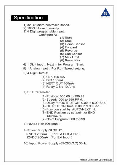
Specification
1) 32 Bit Micro-controller Based.2) 100% Noise Immunity.3) 4 Digit programable Input. Configure As:
(1) Start(2) Stop(3) Home Sensor(4) Forward (5) Reverse(6) End Sensor (7) Max Limit (8) Reset Key
7) SET Parameter:
6) 4 Digit Output:
(1) CLK 100 mA(2) DIR 100mA(3) NEXT OUT 100mA(4) Relay C-No 10 Amp
(1) Position: 000.00 to 999.99 (2) Speed: 000 to 999 RPM (3) Delay for OUTPUT ON: 0.00 to 9.99 Sec. (4) OUTPUT ON Time: 0.00 to 9.99 Sec. (5) Function start by: AUTO/NEXT IN. (6) END Position by set point or END SENSOR (7) No of Program: 000 to 999
8) RS485 Port (Optional). 9) Power Supply OUTPUT:
10) Input Power Supply (85-265VAC) 50Hz
5 VDC 200mA (For Ext CLK & Dir ) 12VDC 200mA (For Ext Input )
Motion Controller User Manual
4) 1 Digit Input : Next in for Program Start. 5) 1 Analog Input : For Run Speed setting.
.
.
Motion Controller User Manual
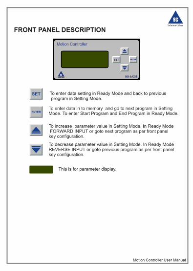
FRONT PANEL DESCRIPTION
SET To enter data setting in Ready Mode and back to previous program in Setting Mode.
ENTERTo enter data in to memory and go to next program in SettingMode. To enter Start Program and End Program in Ready Mode.
To increase parameter value in Setting Mode. In Ready Mode FORWARD INPUT or goto next program as per front panel key configuration.
This is for parameter display.
To decrease parameter value in Setting Mode. In Ready ModeREVERSE INPUT or goto previous program as per front panelkey configuration.
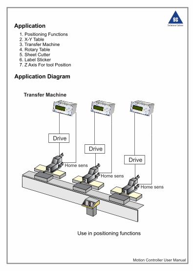
Application
Application Diagram
1. Positioning Functions2. X-Y Table 3. Transfer Machine4. Rotary Table 5. Sheet Cutter 6. Label Sticker7. Z Axis For tool Position
Motion Controller User Manual
Use in positioning functions
Transfer Machine
Drive
Home sens
Drive
Home sens
Drive
Home sens
Motion Controller User Manual
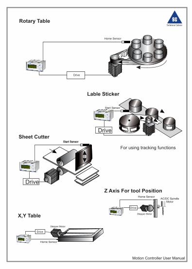
Rotary Table
X,Y Table
Drive
Home SensorAC/DC Spindle
Motor
Stepper Motor
Stepper Motor
Drive
Z Axis For tool Position
Drive
Home Sensor
Drive
Start Sensor
Drive
Start Sensor
Sheet Cutter
For using tracking functions
Lable Sticker
Start Sensor
Home Sensor
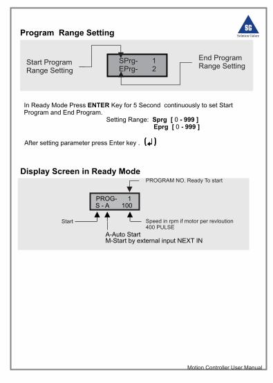
Program Range Setting
SPrg- 1EPrg- 2
Start Program Range Setting
End ProgramRange Setting
Motion Controller User Manual
In Ready Mode Press ENTER Key for 5 Second continuously to set Start Program and End Program.
Setting Range: Sprg [ 0 - 999 ] Eprg [ 0 - 999 ]
After setting parameter press Enter key .
PROG- 1S - A 100
PROGRAM NO. Ready To start
Speed in rpm if motor per revloution400 PULSE Start
Display Screen in Ready Mode
A-Auto StartM-Start by external input NEXT IN
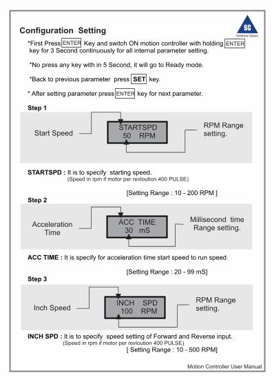
Configuration Setting
*First Press Key and switch ON motion controller with holding key for 3 Second continuously for all internal parameter setting.
*No press any key with in 5 Second, it will go to Ready mode.
*Back to previous parameter press SET key.
* After setting parameter press key for next parameter.
Step 1
STARTSPD : It is to specify starting speed.
[Setting Range : 10 - 200 RPM ]
Step 2
ACC TIME : It is specify for acceleration time start speed to run speed.
[Setting Range : 20 - 99 mS]Step 3
INCH SPD : It is to specify speed setting of Forward and Reverse input.
[ Setting Range : 10 - 500 RPM]
(Speed in rpm if motor per revloution 400 PULSE)
(Speed in rpm if motor per revloution 400 PULSE)
Motion Controller User Manual
STARTSPD 50 RPM
ACC TIME 30 mS
Start Speed
Acceleration Time
RPM Range setting.
Millisecond time Range setting.
ENTER ENTER
ENTER
INCH SPD 100 RPMInch Speed
RPM Range setting.
Motion Controller User Manual
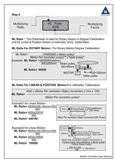
Step 4
ML Ratio : This Parameter is used for Rotary Motion in Degree Caliberation and for Linear & Position Motion in millimeter (mm) Caliberation.
ML Ratio For ROTARY Motion : For Rotary Motion Degree Caliberation. ML Ratio= 144000000 x Motor pulley* (Motor Per revolution pulse)** x Table pulley*Example- ML Ratio= 144000000x50mm 400x200mm Motor pulley OD=50mm ML Ratio= 90000 MOTOR OD=200mm Table pulley
ML Ratio For LINEAR & POSITION Motion:For millimeter Caliberation. 4000 x (Motor Per revolution Object movement in mm x 100) ML Ratio= (Motor Per revolution pulse)* Example1 for Linear Motion- ML Ratio= 4000x(200.16mmx100) 400 ML Ratio= 4000x20016 400 ML Ratio= 200160 Example2 for Linear Motion- ML Ratio= 4000x(100.08mmx100) 400 ML Ratio= 4000x10008 400 ML Ratio= 100080
ML . Ratio 4000
Multiplying Ratio
MultiplyingFactor
Motor Pulling Roller Circumference200.16mm
Motor Per revolution Object movement 200.16 mm
Motor
Pulling Roller Circum.200.16mm
100mm
200mm
Motor Per revolution Object movement Pulling Roller Circumference x Motor pulley* Pulling Roller Pulley*
200.16 x100 200= = 100.08mm
=
Motion Controller User Manual
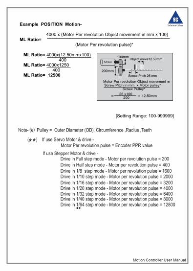
Example POSITION Motion- 4000 x (Motor Per revolution Object movement in mm x 100) ML Ratio= (Motor Per revolution pulse)* ML Ratio= 4000x(12.50mmx100) 400 ML Ratio= 4000x1250 400 ML Ratio= 12500
[Setting Range: 100-999999]
Motor
100mm
200mm
Motor Per revolution Object movement Screw Pitch in mm x Motor pulley* Screw Pulley*
25 x100 200= = 12.50mm
=
Object move12.50mm
Screw Pitch 25 mm
If use Stepper Motor & drive -
Drive in Half step mode - Motor per revolution pulse = 400 Drive in 1/8 step mode - Motor per revolution pulse = 1600 Drive in 1/10 step mode - Motor per revolution pulse = 2000 Drive in 1/16 step mode - Motor per revolution pulse = 3200 Drive in 1/20 step mode - Motor per revolution pulse = 4000 Drive in 1/32 step mode - Motor per revolution pulse = 6400 Drive in 1/40 step mode - Motor per revolution pulse = 8000 Drive in 1/64 step mode - Motor per revolution pulse = 12800
Motor Per revolution pulse = Encoder PPR value
Note- Pulley = Outer Diameter (OD), Circumference ,Radius ,Teeth
*
( )
( ) If use Servo Motor & drive - * *
Drive in Full step mode - Motor per revolution pulse = 200
MaximumLimit
Length
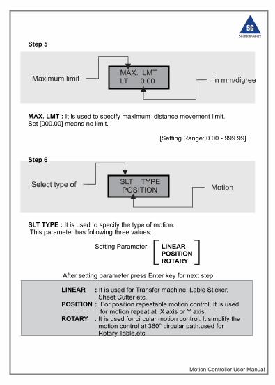
Step 5
MAX. LMT : It is used to specify maximum distance movement limit.Set [000.00] means no limit.
[Setting Range: 0.00 - 999.99]
Step 6
SLT TYPE : It is used to specify the type of motion. This parameter has following three values:
Setting Parameter: LINEARPOSITIONROTARY
After setting parameter press Enter key for next step.
LINEAR : It is used for Transfer machine, Lable Sticker, Sheet Cutter etc.
POSITION : For position repeatable motion control. It is used for motion repeat at X axis or Y axis.
ROTARY : It is used for circular motion control. It simplify the motion control at 360° circular path.used for
Rotary Table,etc
Motion Controller User Manual
MAX. LMTLT 0.00
SLT TYPE POSITION MotionSelect type of
Maximum limit in mm/digree
Select Type
Motion Controller User Manual
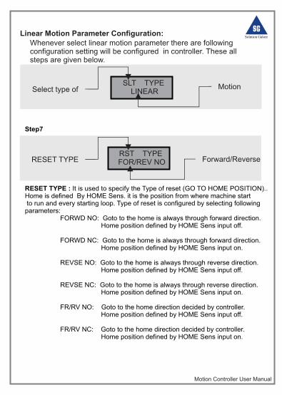
Linear Motion Parameter Configuration:Whenever select linear motion parameter there are following configuration setting will be configured in controller. These all steps are given below.
SLT TYPE LINEAR
Step7
RESET TYPE : It is used to specify the Type of reset (GO TO HOME POSITION)..Home is defined By HOME Sens. it is the position from where machine start to run and every starting loop. Type of reset is configured by selecting followingparameters: FORWD NO: Goto to the home is always through forward direction. Home position defined by HOME Sens input off.
FORWD NC: Goto to the home is always through forward direction. Home position defined by HOME Sens input on.
REVSE NO: Goto to the home is always through reverse direction. Home position defined by HOME Sens input off.
REVSE NC: Goto to the home is always through reverse direction. Home position defined by HOME Sens input on.
FR/RV NO: Goto to the home direction decided by controller. Home position defined by HOME Sens input off.
FR/RV NC: Goto to the home direction decided by controller. Home position defined by HOME Sens input on.
RST TYPE FOR/REV NO
MotionSelect type of
RESET TYPE Forward/Reverse
ONAUTO RESET
Motion Controller User Manual
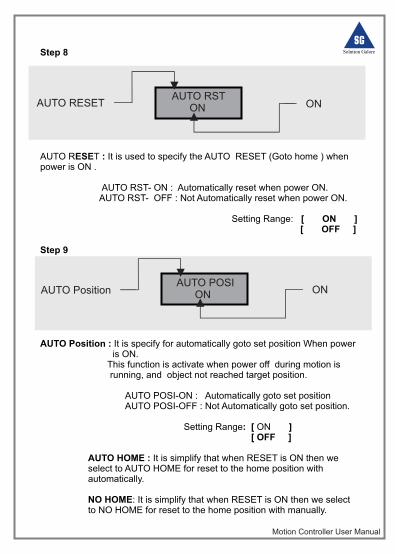
Step 8
AUTO RESET : It is used to specify the AUTO RESET (Goto home ) when power is ON .
AUTO RST- ON : Automatically reset when power ON. AUTO RST- OFF : Not Automatically reset when power ON. Setting Range: [ ON ]
[ OFF ]
Step 9
AUTO Position : It is specify for automatically goto set position When power is ON. This function is activate when power off during motion is running, and object not reached target position.
AUTO POSI-ON : Automatically goto set position AUTO POSI-OFF : Not Automatically goto set position.
Setting Range: [ ON ] [ OFF ]
AUTO HOME : It is simplify that when RESET is ON then we select to AUTO HOME for reset to the home position with automatically.
NO HOME: It is simplify that when RESET is ON then we select to NO HOME for reset to the home position with manually.
AUTO RST ON
AUTO POSI ONAUTO Position ON
AUTO RESET ON
Motion Controller User Manual
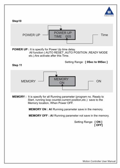
Step10
POWER UP : It is specify for Power Up time delay. All function ( AUTO RESET ,AUTO POSITION ,READY MODE etc.) Are activate after this Time. Setting Range : [ 0Sec to 99Sec ]Step 11
MEMORY : It is specify for all Running parameter (program no. Ready to Start, running loop counter,current position,etc.) save to the Memory location, When Power OFF. MEMORY ON : All Running parameter save in the memory. MEMORY OFF : All Running parameter not save in the memory.
Setting Range: [ ON ] [ OFF]
POWER UPTIME 00S
MEMORY ON
POWER UP Time
MEMORY ON
Motion Controller User Manual
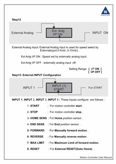
Step12
External Analog input: External Analog input is used for speed select by Externally(pot,0-5vdc ,0-10vdc) .
Ext Anlg I/P ON : Speed set by externally analog input .
Ext Anlg I/P OFF : externally analog input off.
Setting Range: [ I/P ON ] [ I/P OFF ]
Step13: External INPUT Configuration
INPUT 1, INPUT 2, INPUT 3, INPUT 4 : These inputs configure are follows :
1- START : For motion controller start .
2- STOP : For motion controller stop .
3- HOME SENS : For Home position sensor . 4- END SENS : For End position sensor .
5- FORWARD :For Manually forward motion .
6- REVERSE : For Manually reverse motion .
7- MAX LIMIT : For Maximum Limit of forward motion .
8- RESET : For External RESET(Goto Home) .
Ext Anlg I/P ON
INPUT (1) START
INPUT 1 Fun START
External Analog INPUT ON
Motion Controller User Manual
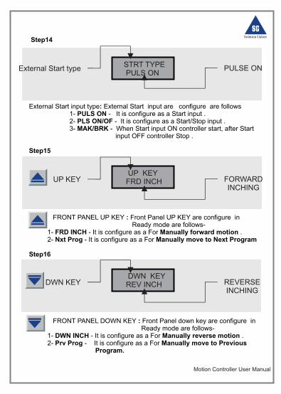
Step14
External Start input type: External Start input are configure are follows 1- PULS ON - It is configure as a Start input . 2- PLS ON/OF - It is configure as a Start/Stop input . 3- MAK/BRK - When Start input ON controller start, after Start input OFF controller Stop .
Step15
FRONT PANEL UP KEY : Front Panel UP KEY are configure in Ready mode are follows- 1- FRD INCH - It is configure as a For Manually forward motion . 2- Nxt Prog - It is configure as a For Manually move to Next Program
Step16
FRONT PANEL DOWN KEY : Front Panel down key are configure in Ready mode are follows- 1- DWN INCH - It is configure as a For Manually reverse motion . 2- Prv Prog - It is configure as a For Manually move to Previous Program.
STRT TYPE PULS ON
External Start type PULSE ON
UP KEY FRD INCHUP KEY FORWARD
INCHING
DWN KEY REV INCHDWN KEY REVERSE
INCHING
Motion Controller User Manual
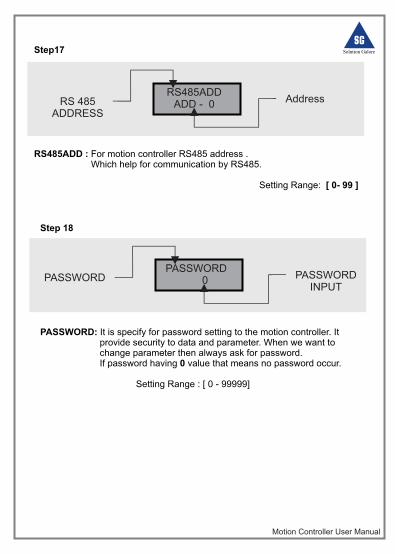
Step 18
PASSWORD: It is specify for password setting to the motion controller. It provide security to data and parameter. When we want to change parameter then always ask for password. If password having 0 value that means no password occur.
Setting Range : [ 0 - 99999]
PASSWORD 0PASSWORD PASSWORD
INPUT
RS485ADDADD - 0RS 485
ADDRESS
Address
Step17
RS485ADD : For motion controller RS485 address . Which help for communication by RS485.
Setting Range: [ 0- 99 ]
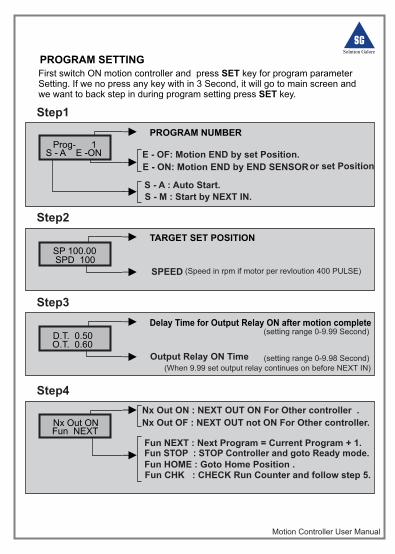
PROGRAM SETTING
Motion Controller User Manual
Prog- 1S - A E -ON
PROGRAM NUMBER
E - ON: Motion END by END SENSOR
S - A : Auto Start.
S - M : Start by NEXT IN.
E - OF: Motion END by set Position.or set Position
First switch ON motion controller and press SET key for program parameter Setting. If we no press any key with in 3 Second, it will go to main screen and we want to back step in during program setting press SET key.
Step1
SP 100.00SPD 100
TARGET SET POSITION
SPEED
Step2
(Speed in rpm if motor per revloution 400 PULSE)
D.T. 0.50 O.T. 0.60
Delay Time for Output Relay ON after motion complete
Output Relay ON Time
Step3
Nx Out ON Fun NEXT
Fun HOME : Goto Home Position .
Fun CHK : CHECK Run Counter and follow step 5.
Nx Out ON : NEXT OUT ON For Other controller .
Step4
(setting range 0-9.99 Second)
(setting range 0-9.98 Second)(When 9.99 set output relay continues on before NEXT IN)
Nx Out OF : NEXT OUT not ON For Other controller.
Fun STOP : STOP Controller and goto Ready mode.Fun NEXT : Next Program = Current Program + 1.
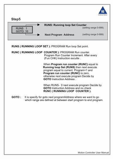
RUNS ( RUNNING LOOP SET ): PROGRAM Run loop Set point. RUNC ( RUNNING LOOP COUNTER ): PROGRAM Run counter. Program Run Counter Increment After every (Fun CHK) Instruction excutte . When Program run counter (RUNC) equal to
Running loop Set (RUNS) then next execute program equal to current Program+1 and Program run counter (RUNC) is zero, otherwise next execute program Decide by GOTO Instruction Address .
When RUNS- 0 next execute program Decide by GOTO Instruction Address and no check RUNC ( RUNNING LOOP COUNTER ).
GOTO : It is specify for goto next programAddress where we want to go which range are defined at between start program to end program.
Motion Controller User Manual
RUNS 1GOTO 10
RUNS: Running loop Set Counter
Next Program Address
Step5
(setting range 0-999)
(setting range 0-999)
Motion Controller User Manual
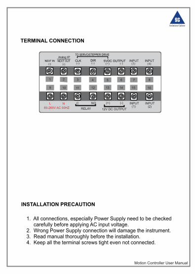
TERMINAL CONNECTION
1 2 3 4 5 6
9 10 11 12 13 14
L N C NO (+) (-)
(-)(+)(-)(-)
12V DC OUTPUTRELAY85-265V AC 50HZ
5VDC OUTPUTDIRCLK
TO SERVO/STEPPER DRIVE
INPUT
INPUT
INPUT
INPUT
(1)
(3)
(2)
(4)
15 16
7 8
NEXT IN(-)
Analog I/P
NEXT OUT(-)
INSTALLATION PRECAUTION
1. All connections, especially Power Supply need to be checked carefully before applying AC input voltage. 2. Wrong Power Supply connection will damage the instrument.3. Read manual thoroughly before the installation.4. Keep all the terminal screws tight even not connected.
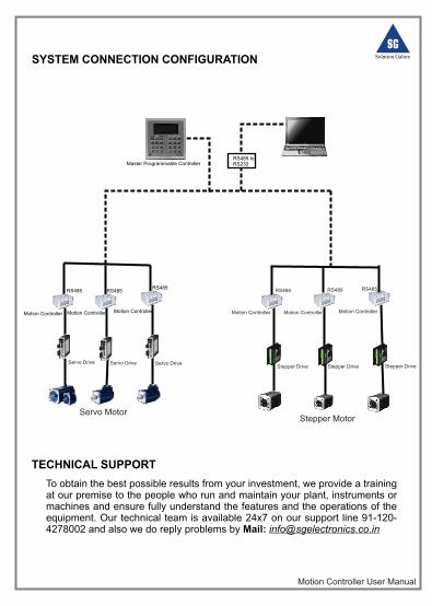
SYSTEM CONNECTION CONFIGURATION
TECHNICAL SUPPORT
Servo Drive Servo DriveStepper Drive Stepper Drive Stepper Drive
Servo Drive
Motion Controller Motion Controller Motion Controller Motion ControllerMotion Controller Motion Controller
Servo MotorStepper Motor
RS485 RS485RS485 RS485RS485 RS485
PC
Master Programmable ControllerRS485 to RS232
To obtain the best possible results from your investment, we provide a training at our premise to the people who run and maintain your plant, instruments or machines and ensure fully understand the features and the operations of the equipment. Our technical team is available 24x7 on our support line 91-120-4278002 and also we do reply problems by Mail: [email protected]
Motion Controller User Manual