Embed Size (px)
Citation preview

Abstract—This study aims at the development of a motion
control design for controlling robotic walking support systems
using a force-controlled motion command generator so that
robotic walking support systems can provide smooth motions to
users with desired motion speeds. The motion control laws are
implemented with a low-pass filter that has adjustable gain and
bandwidth. Through the cooperation of motion control laws and
force-sensing results, the force-controlled motion command
generator can generate smooth motion commands to smoothly
drive robotic walking support systems. A simple and low-cost
biaxial force-sensing device is developed in this study to estimate
the equivalent interactive forces between the user and the
robotic walking support system. A calibration procedure is also
developed to obtain the virtual spring coefficient and to design
an estimation method that can be used with the biaxial force-
sensing device. A robotic walking support system, the robotic
cane, is developed with two operation modes, autonomous
motion mode (AMM) and manual motion mode (MMM), for
testing the proposed motion control approach, and several tests
and experimental results are presented to show the validity of
the proposed approach.
Index Terms—robotic walking support system, motion
control design, force-controlled motion command generator,
force-sensing device, robotic cane
I. INTRODUCTION
N a society that is constantly aging, walking support
systems have become important for the elderly because
they can assist them in their daily activities so that they
can regain independence and have improved quality of life.
The most common walking support systems include crutches,
walkers, and canes. A crutch is usually used as a tool for
patients suffering from lower limb problems when they walk
large distances. Therefore, aged people whose lower limbs
are in normal condition but face difficulties in walking may
use walkers or canes to help them walk. Such devices are
usually used to maintain body balance, support weight, train
to walk, and increase muscle strength of lower limbs. Besides,
Manuscript received May 18, 2011. This work was supported in part by
the National Science Council of the Republic of China under Contract NSC
99-2221-E-027-009 and the Industrial Technology Research Institute of the
Republic of China under project number 9353C72000, which is
subcontracted from the Ministry of Economic Affairs, Taiwan.
Yong-Zeng Zhang is with the Institute of Mechatronic Engineering,
National Taipei University of Technology, Taipei, Taiwan (e-mail:
Syh-Shiuh Yeh is with the Department of Mechanical Engineering,
National Taipei University of Technology, Taipei, Taiwan (phone: +886-2-
2771-2171; fax: +886-2-2731-7191; e-mail: [email protected]).
canes are also available for visually impaired people to help
them detect road situations while walking. Although
conventional walking support systems are usually used to
solve mobility problems in the elderly, they are considered as
passive devices and their motions strictly depend on the user’s
decision to apply forces/torques to them. Therefore, the users
of these conventional walking support systems must be
capable of functions such as sufficient cognitive function,
good vision, judgment, and endurance, all of which are
difficult to satisfy for the elderly because these functions
degrade with aging.
In recent decades, because of the rapid development of
robotic technologies, including actuating and sensing devices,
robotic technologies are widely and diversely being
introduced into conventional walking support systems, and
the developed robotic walking support systems can normally
provide much better walk-assisting performances. Lacey and
Dawson-Howe [1] described an application of mobile robot
technology to provide robot mobility aid for the frail blind;
further, the PAM-AID mobile robot [2] consisting of a
walking frame with wheels was developed to help avoid
obstacles and physically support the person walking. For
helping the elderly live independently in their private living
environments, a robotic assistant named Care-O-bot II [3]
was developed with adjustable walking supporters to support
and guide the elderly people safely while they walked in
indoor environments. Hirata et al. [4] proposed a passive
intelligent walker named RT Walker to assist elderly and
handicapped people walking in both indoor and outdoor
environments. The developed adaptive motion control
algorithm facilitates the mechanical behaviors of the RT
Walker to adapt to user operation, and it helps avoid obstacles
according to the extracted environmental information. Chuy
Jr. et al. [5][6] developed the Walking Helper, which
considers user operation characteristics to aid users in
controlling their walking support system; further, Chuy Jr. et
al. [7] developed a motorized robotic walking support system
based on the passive behavior concept proposed by Hirata et
al. [4] to enhance the interaction between the walking support
system and the user. Wasson et al. [8] presented an operation
system that can infer the navigational intent of a walker’s user
based on the measured forces and moments applied to the
handles of the walker. Morris et al. [9] proposed a robotic
walker that integrates a haptic interface and a robot
localization and navigation system to provide mobility aid to
frail elderly people with cognitive impairment. Sabatini et al.
[10] developed a motorized rollator that is equipped with
Motion Control Design for an Economical
Robotic Walking Support System:
The Robotic Cane
Yong-Zeng Zhang and Syh-Shiuh Yeh
I
Engineering Letters, 19:3, EL_19_3_06
(Advance online publication: 24 August 2011)
______________________________________________________________________________________
force, ultrasonic, and infrared sensors to support elderly
people in walking while avoiding collisions. Spenko et al. [11]
developed a smart walker that provides support, guidance,
and health monitoring for the elderly in an assisted living
facility. The developed smart walker uses a six-axis
force/torque sensor attached at the walker’s handle as the
main control input interface. Further, a shared adaptive
control algorithm was developed to control the smart walker
by a computer controller such that the smart walker gently
guided the user. Although current successfully developed
robotic walkers can offer support and safety guidance, their
larger size hinders normal footsteps. Therefore, Spenko et al.
[11] developed a smart cane that provides functions similar to
those of the smart walker. Although some cane robots such as
the Walking Guide Robot [12], RoJi Robot [13], Guide Cane
Robot [14], and the Robotic Cane proposed by Aigner and
McCarragher [15] can provide good guiding performances
for the visually impaired and the elderly, they cannot
physically support the elderly during walking.
Although existing researches have demonstrated important
results, meeting the needs of the elderly, such as the
requirement of smooth motion and low-cost force-sensing
devices for controlling robotic walking support systems,
remains a challenge. Despite high-level applications such as
walking guidance and health monitoring being useful for the
elderly during walking, motion control design of robotic
walking support systems is important because the motion
results of robotic walking support systems significantly affect
the walking behaviors of the elderly. Some existing
researches have focused on the study of the interaction
behaviors between humans and an applied robotic walking
support system by considering the dynamic characteristics of
the applied robotic walking support system. However, the
motion control system of robotic walking support systems
must be implemented by considering the design of a motion
command generator in order to provide smooth motion
commands and to smoothly guide the elderly with the desired
walking speeds.
In this study, the design of a force-controlled motion
command generator is newly developed by considering the
interactive forces/torques between humans and a robotic
walking support system. The system can provide smooth
motion with the desired speed of motion. In order to detect
interactive forces/torques between humans and the robotic
walking support system, a force/torque sensor is an essential
component. However, sensors used to detect the interactive
forces/torques in robotic walking support systems are usually
designed for industrial applications, and they are normally
expensive. Therefore, it is desired to design a cheap and
simple force-sensing device that can be used to control
robotic walking support systems and can thus reduce the cost
for wide applications and general users. In this study, a simple
biaxial force-sensing device is developed for estimating the
interactive forces between humans and robotic walking
support systems. In addition, methods of calibration and
control using the force-sensing device are addressed.
In order to illustrate the design and application of the
force-controlled motion command generator and the biaxial
force-sensing device, a robotic walking support system, the
robotic cane, is developed with adequate motion control
design. The robotic cane is composed of a two-wheeled
mobile platform with three range sensors, a cane-stick with
handgrip, and a biaxial force-sensing device. Moreover, the
robotic cane is designed to provide the following two
operation modes:
• Autonomous motion mode (AMM): the robotic cane
autonomously moves in walking environments along
preplanned motion paths with the desired linear and
angular velocities according to the signals sensed by range
sensors.
• Manual motion mode (MMM): the robotic cane moves
along preplanned motion paths with the adjustable linear
velocity command closely related to the forces exerted by
the user’s hand.
Several simulations and experiments are carried out to test the
execution performances of the force-controlled motion
command generator implemented in the motion control
design of the robotic cane. The experimental results indicate
that the motion control design with the force-controlled
motion command generator allows the robotic cane to execute
different motions according to the selected operation modes.
This paper is organized in detail as follows. Section II
presents the mechanical design of the robotic cane. The
mechanism of the biaxial force-sensing device is also
presented in this section. Section III to Section VI describe
the motion control design of the robotic cane. Section III
illustrates the architecture of motion control design; Section
IV presents the design and selection of motion paths for the
robotic cane; Section V presents the design of the force-
controlled motion command generator; and Section VI
describes the motion control laws cooperating with the
force-controlled motion command generator. Section VII
shows some simulation and experimental results of cases
when the robotic cane executes different motions. Calibration
and tests of the biaxial force-sensing device are also
introduced in this section. Section VIII concludes this paper.
II. MECHANICAL DESIGN OF THE ROBOTIC CANE
Fig. 1 shows the design of the robotic cane. The robotic
cane consists of three main parts: a cane-stick with handgrip, a
force-sensing device, and a two-wheeled mobile platform.
The two-wheeled mobile platform is equipped with two
standard drive wheels, two castor wheels, main control unit,
main power and auxiliary power units, ultrasonic range sensor,
two infrared range sensors, and a touch-screen panel. The two
standard drive wheels are used to drive the mobile platform by
the differential spinning speeds of the left and right drive
wheels such that the mobile platform can execute linear
motion and rotational motion about the instantaneous center
of rotation (ICR). The two castor wheels are free rotation
wheels and are used to support the mobile platform. The
motion control design is implemented in the main control unit
composed of a data acquisition board, a motion control board,
and a personal computer (PC) with a Pentium dual-core CPU.
The main control unit receives sensing signals from force-
sensing device and ultrasonic and infrared range sensors; the
main control unit also sends the generated control signals to
two standard drive wheels to control the motion of the mobile
platform. The main power unit provides the required power to
Engineering Letters, 19:3, EL_19_3_06
(Advance online publication: 24 August 2011)
______________________________________________________________________________________
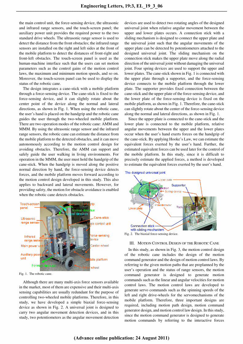
the main control unit, the force-sensing device, the ultrasonic
and infrared range sensors, and the touch-screen panel; the
auxiliary power unit provides the required power to the two
standard drive wheels. The ultrasonic range sensor is used to
detect the distance from the front obstacles; the infrared range
sensors are installed on the right and left sides at the front of
the mobile platform to detect the distances of front-right and
front-left obstacles. The touch-screen panel is used as the
human-machine interface such that the users can set motion
parameters such as the control gains of the motion control
laws, the maximum and minimum motion speeds, and so on.
Moreover, the touch-screen panel can be used to display the
status of the robotic cane.
The design integrates a cane-stick with a mobile platform
through a force-sensing device. The cane-stick is fixed to the
force-sensing device, and it can slightly rotate about the
center point of the device along the normal and lateral
directions, as shown in Fig. 1. When using the robotic cane,
the user’s hand is placed on the handgrip and the robotic cane
guides the user through the two-wheeled mobile platform.
There are two operation modes of the robotic cane: AMM and
MMM. By using the ultrasonic range sensor and the infrared
range sensors, the robotic cane can estimate the distance from
the mobile platform to the detected obstacles, and it can move
autonomously according to the motion control design for
avoiding obstacles. Therefore, the AMM can support and
safely guide the user walking in living environments. For
operation in the MMM, the user must hold the handgrip of the
cane-stick. When the handgrip is moved along the positive
normal direction by hand, the force-sensing device detects
forces, and the mobile platform moves forward according to
the motion control design developed in this study. This also
applies to backward and lateral movements. However, for
providing safety, the motion for obstacle avoidance is enabled
when the robotic cane detects obstacles.
Fig. 1. The robotic cane.
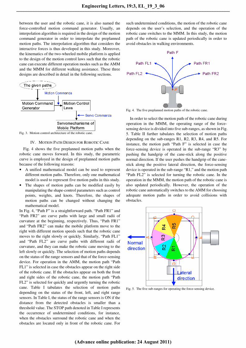
Although there are many multi-axis force sensors available
in the market, most of them are expensive and their multi-axis
sensing capabilities are usually redundant for the purpose of
controlling two-wheeled mobile platforms. Therefore, in this
study, we have developed a simple biaxial force-sensing
device as shown in Fig. 2. A universal joint is designed to
carry two angular movement detection devices, and in this
study, two potentiometers as the angular movement detection
devices are used to detect two rotating angles of the designed
universal joint when relative angular movement between the
upper and lower plates occurs. A connection stick with a
sliding mechanism is designed to connect the upper plate and
the universal joint such that the angular movements of the
upper plate can be detected by potentiometers attached to the
designed universal joint. The sliding mechanism on the
connection stick makes the upper plate move along the radial
direction of the universal joint without damaging the universal
joint. Four spring devices are used to support the upper and
lower plates. The cane-stick shown in Fig. 1 is connected with
the upper plate through a supporter, and the force-sensing
device connects to the mobile platform through the lower
plate. The supporter provides fixed connection between the
cane-stick and the upper plate of the force-sensing device, and
the lower plate of the force-sensing device is fixed on the
mobile platform, as shown in Fig. 1. Therefore, the cane-stick
can slightly rotate about the center of the force-sensing device
along the normal and lateral directions, as shown in Fig. 1.
Since the upper plate is connected to the cane-stick and the
lower plate is connected to the mobile platform, relative
angular movements between the upper and the lower plates
occur when the user’s hand exerts forces on the handgrip of
the cane-stick. By applying Hooke’s Law, we can estimate the
equivalent forces exerted by the user’s hand. Further, the
estimated equivalent forces can be used later for the control of
the mobile platform. In this study, since it is difficult to
precisely estimate the applied forces, a method is developed
to estimate the equivalent forces exerted by the user’s hand.
Fig. 2. The biaxial force-sensing device.
III. MOTION CONTROL DESIGN OF THE ROBOTIC CANE
In this study, as shown in Fig. 3, the motion control design
of the robotic cane includes the design of the motion
command generator and the design of motion control laws. By
referring to the given motion paths that are preplanned by the
user’s operation and the status of range sensors, the motion
command generator is designed to generate motion
commands such as the linear and angular velocities for motion
control laws. The motion control laws are developed to
generate servo commands such as the spinning speeds of the
left and right drive-wheels for the servomechanisms of the
mobile platform. Therefore, three important designs are
required, including motion path design, motion command
generator design, and motion control law design. In this study,
since the motion command generator is designed to generate
motion commands by referring to the interactive forces
Engineering Letters, 19:3, EL_19_3_06
(Advance online publication: 24 August 2011)
______________________________________________________________________________________
between the user and the robotic cane, it is also named the
force-controlled motion command generator. Usually, an
interpolation algorithm is required in the design of the motion
command generator in order to interpolate the preplanned
motion paths. The interpolation algorithm that considers the
interactive forces is thus developed in this study. Moreover,
the kinematics of the two-wheeled mobile platform is applied
to the design of the motion control laws such that the robotic
cane can execute different operation modes such as the AMM
and the MMM for different walking assistance. These three
designs are described in detail in the following sections.
Fig. 3. Motion control architecture of the robotic cane.
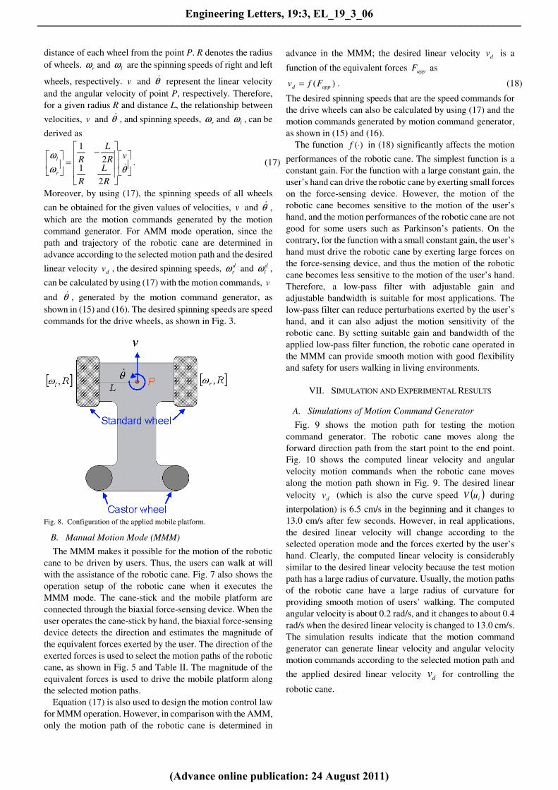
IV. MOTION PATH DESIGN FOR ROBOTIC CANE
Fig. 4 shows the five preplanned motion paths when the
robotic cane moves forward. In this study, the parametric
curve is employed in the design of preplanned motion paths
because of the following reasons:
• A unified mathematical model can be used to represent
different motion paths. Therefore, only one mathematical
model is used to represent five motion paths in this study.
• The shapes of motion paths can be modified easily by
manipulating the shape-control parameters such as control
points, weights, and knots. Therefore, the shapes of
motion paths can be changed without changing the
mathematical model.
In Fig. 4, “Path F” is a straightforward path. “Path FR1” and
“Path FR2” are curve paths with large and small radii of
curvature at the beginning, respectively. Thus, “Path FR1”
and “Path FR2” can make the mobile platform move to the
right with different motion speeds such that the robotic cane
moves to the right slowly or quickly. Similarly, “Path FL1”
and “Path FL2” are curve paths with different radii of
curvature, and they can make the robotic cane moving to the
left slowly or quickly. The selection of motion paths depends
on the status of the range sensors and that of the force-sensing
device. For operation in the AMM, the motion path “Path
FL1” is selected in case the obstacles appear on the right side
of the robotic cane. If the obstacles appear on both the front
and right sides of the robotic cane, the motion path “Path
FL2” is selected for quickly and urgently turning the robotic
cane. Table I tabulates the selection of motion paths
depending on the status of the front, left, and right range
sensors. In Table I, the status of the range sensors is ON if the
distance from the detected obstacles is smaller than a
threshold value. The STOP path denoted in Table I represents
the occurrence of undetermined conditions, for instance,
when the obstacles surround the robotic cane and when the
obstacles are located only in front of the robotic cane. For
such undetermined conditions, the motion of the robotic cane
depends on the user’s selection, and the operation of the
robotic cane switches to the MMM. In this study, the motion
path of the robotic cane is updated periodically in order to
avoid obstacles in walking environments.
Fig. 4. The five preplanned motion paths of the robotic cane.
In order to select the motion path of the robotic cane during
operation in the MMM, the operating range of the force-
sensing device is divided into five sub-ranges, as shown in Fig.
5. Table II further tabulates the selection of motion paths
depending on the sub-ranges R1, R2, R3, R4, and R5. For
instance, the motion path “Path F” is selected in case the
force-sensing device is operated in the sub-range “R3” by
pushing the handgrip of the cane-stick along the positive
normal direction. If the user pushes the handgrip of the cane-
stick along the positive lateral direction, the force-sensing
device is operated in the sub-range “R1,” and the motion path
“Path FL2” is selected for turning the robotic cane. In the
operation in the MMM, the motion path of the robotic cane is
also updated periodically. However, the operation of the
robotic cane automatically switches to the AMM for choosing
adequate motion paths in order to avoid collisions with
obstacles.
Fig. 5. The five sub-ranges for operating the force-sensing device.
Engineering Letters, 19:3, EL_19_3_06
(Advance online publication: 24 August 2011)
______________________________________________________________________________________

TABLE I
THE SELECTION OF MOTION PATHS (AMM)
Front ultrasonic range
sensor is OFF
Front ultrasonic range
sensor is ON
Right infrared range sensor
is
Right infrared range sensor
is
OFF ON OFF ON
Left infrared
range sensor is
OFF
Path F Path FL1 STOP Path FL2
Left infrared
range sensor is
ON
Path FR1 Path F Path FR2 STOP
TABLE II
THE SELECTION OF MOTION PATHS (MMM)
Sub-range
R1 R2 R3 R4 R5
Motion
Path
Path FL2 Path FL1 Path F Path FR1 Path FR2
V. DESIGN OF THE FORCE-CONTROLLED MOTION COMMAND
GENERATOR
Since the preplanned motion paths are represented by
parameter curve functions, the motion command generator
shown in Fig. 3 requires an interpolation algorithm to
interpolate the given motion path and successively generate
the interpolated points on the given motion path, as shown in
Fig. 6. A parameter iteration method is thus developed to
interpolate the parametric curve function, and the interpolated
points are obtained by computing the curve function with the
iterated parameters [16].
Fig. 6. The successive interpolated points on the given path.
Suppose that ( )uC is a parametric curve function that
represents the given motion path, and the time function u is
the curve parameter. The curve speed ( )uV and curve
acceleration ( )uA can be derived as follows:
( ) ( ) ( )dt
du
du
udC
dt
udCuV ⋅== (1)
( ) ( ) ( ) ( )
( ) ( ) 2
2
2
2
2
2
2
2
2
⋅+⋅=
⋅
+⋅==
dt
du
du
uCd
dt
ud
du
udC
dt
du
du
udC
dt
d
dt
ud
du
udC
dt
uCduA
(2)
The functions u
iD , t
iD , 2u
iD , and 2t
iD are defined as follows:
( )
iuu
u
idu
udCD
=
= ; ( )
itt
t
idt
udCD
=
= (3)
( )
iuu
u
idu
uCdD
=
=2
22
; ( )
itt
t
idt
uCdD
=
=2
22
(4)
where iu denotes the value of u at time itt = . Then, (1) and
(2) can be rewritten as follows:
( )dt
duDDuV
u
i
t
ii ⋅== (5)
( )2
2
2
22
⋅+⋅==
dt
duD
dt
udDDuA u
i
u
i
t
ii (6)
Using (3) and (4), (5) and (6) can be further rewritten as
follows:2
, ,
⋅=
dt
duDDDD u
i
u
i
t
i
t
i (7)
t
i
t
i
u
i
u
i
u
i
u
i
u
i
u
i
u
i
u
i
u
i
u
i
u
i
u
i
t
i
DDDdt
udDDD
dt
duDDD
dt
udDDD
DDD
, ,
, ,
,
2
2
2
2
2
2
2
2
⋅+⋅⋅=
⋅⋅+⋅⋅=
⋅
or
u
i
u
i
t
i
t
iu
i
u
i
t
iDD
DDD
dt
udDD
,
,2
2
22 ⋅+⋅= (8)
where < , > is an inner product operator. Since the curve
parameter u is a time function, the approximation by using
Taylor’s expansion up to the second derivative is given by
( )
( ) TOHttdt
ud
ttdt
duuu
ii
tt
ii
tt
ii
i
i
..2
1
2
12
2
11
+−⋅⋅+
−⋅+=
+
=
+
=
+
(9)
Substituting (5)–(8) into (9) and neglecting the higher order
terms (H.O.T.) in (9), we can rewrite (9) as follows:
( ) ( )
( ) ( )2
12
2
1
2
12
2
1
1
2
1
2
1
ii
tt
u
iii
t
ii
u
i
ii
tt
u
iii
tt
u
ii
u
i
i
u
i
ttdt
udDttDuD
ttdt
udDtt
dt
duDuD
uD
i
ii
−⋅⋅⋅+−⋅+⋅=
−⋅⋅⋅+−⋅⋅+⋅=
⋅
+
=
+
+
=
+
=
+
(10)
Substituting (8) into (10), we can further rewrite (10) as
follows:
( )
( )2
1
22
11
,
,
2
1 iiu
i
u
i
t
i
t
iu
i
t
i
ii
t
ii
u
ii
u
i
ttDD
DDDD
ttDuDuD
−⋅
⋅−⋅+
−⋅+⋅=⋅
+
++
(11)
Let the time step in the interpolation be sT seconds and
sii Ttt =−+1
Then, the parameter iteration algorithm can be obtained from
(11) by
Engineering Letters, 19:3, EL_19_3_06
(Advance online publication: 24 August 2011)
______________________________________________________________________________________

2
2
22
1
,
, ,
,
,
2
1
,
,
su
i
u
i
t
i
t
i
u
i
u
i
u
i
u
i
t
i
u
i
su
i
u
i
t
i
u
i
ii
T
DD
DDDD
DD
DD
TDD
DDuu
⋅
⋅−⋅+
⋅+=+
(12)
Because
( ) u
ii
t
i
u
i DuVDD ⋅= , ; 2
, u
i
u
i
u
i DDD =
0 , 2 =t
i
u
i DD ; ( )i
t
i
t
i uVDD 2 , =
Equation (12) can be rewritten as follows:
( ) ( )4
222
1
,
2
1
u
i
si
u
i
u
i
u
i
siii
D
TuVDD
D
TuVuu
⋅⋅⋅−
⋅+=+ (13)
where ( )iuV is the curve speed along the tangent at iuu =
and ⋅ is the Euclidean norm operator. Equation (13) can be
further simplified to the first order by
( )u
i
siii
D
TuVuu
⋅+=+1 (14)
Equations (13) and (14) are the expressions of the parameter
iteration method in this study. For the given iu , sT , and
( )iuV and curve information such as u
iD and 2u
iD , the
parameter 1+iu can be obtained from (13) or (14).
For computing the motion commands such as the linear
velocity )(tv and the angular velocity )(tθ& at time itt = , the
interpolated point )( 1+iuC must be calculated by using the
iteration method shown in (13) or (14). Suppose that )( 1−iuC ,
)( iuC , and )( 1+iuC are the successive and adjacent
interpolated points given as
11
)( ;)()( 11−− =−=− ==
ii ttiuui tuuuCuC
ii ttiuui tuuuCuC==
== )( ;)()(
11
)( ;)()( 11++ =+=+ ==
ii ttiuui tuuuCuC
Then, as shown in Fig. 6, the length iα and the angle iβ are
computed by
)()( 1i ii uCuC −= +α
))()()()(
])()([)]()([(sin
11
111
i
iiii
iiii
uCuCuCuC
uCuCuCuC
−⋅−
−×−=
+−
+−−β
where × is a cross product operator. The linear velocity )(tv
and the angular velocity )(tθ& at time itt = are obtained by
stti
Ttvtv
i
i)()(α
===
(15)
stt
iT
tti
i)()(β
θθ ===
&& (16)
where sT is the time step in interpolation and is also the
sampling period in control system. By using the iteration
method shown in (13) or (14) with the given curve speed
( )iuV , the linear velocity )( itv can be approximated to the
given curve speed ( )iuV . For paths with large radii of
curvature, the iteration method in (14) can provide good
approximation results. However, for paths with small radii of
curvature, the iteration method in (13) should be considered
for obtaining good approximation results. In this study, the
given curve speed ( )uV at time itt = is the desired linear
velocity dv defined in the motion control laws (described in
section VI) such that the robotic cane can execute different
motions according to the selected operation modes. Since the
desired linear velocity dv is a function of the interactive
forces between the user and the robotic cane, the interpolation
algorithm developed in this section can be used to generate
motion commands that are closely related to the interactive
forces. Thus, the force-controlled motion command generator
developed by applying the interpolation algorithm can
generate motion commands closely related to the interactive
forces.
VI. DESIGN OF OPERATION MODES AND MOTION CONTROL
LAWS
The robotic cane can provide two operation modes: AMM
and MMM. These two operation modes are described as
follows.
A. Autonomous Motion Mode (AMM)
The operation in the AMM can autonomously move the
robotic cane through a preplanned motion path with a given
velocity trajectory. Fig. 7 shows the operation setup of the
robotic cane when it executes the AMM mode. As shown in
Fig. 7, since a user’s hand holds the handgrip of the cane-stick,
the robotic cane can support and guide the user’s walk
depending on the motion of the mobile platform. For instance,
the user walks forward when the mobile platform moves
forward according to the preplanned motion paths. During the
operation in the AMM mode, the selection of the motion path
of the mobile platform depends on the status of the range
sensors, as shown in Fig. 4 and Table I, and the robotic cane
can thus guide users while avoiding collisions with obstacles.
Fig. 7. Operation setup of the robotic cane.
Motion control laws of the robotic cane are designed by
using the kinematics of the two-wheeled mobile platform. Fig.
8 illustrates the configuration of the two-wheeled mobile
platform used in this study. In Fig. 8, P denotes the point
centered between two drive-wheels, and L denotes the
Engineering Letters, 19:3, EL_19_3_06
(Advance online publication: 24 August 2011)
______________________________________________________________________________________
distance of each wheel from the point P. R denotes the radius
of wheels. rω and lω are the spinning speeds of right and left
wheels, respectively. v and θ& represent the linear velocity
and the angular velocity of point P, respectively. Therefore,
for a given radius R and distance L, the relationship between
velocities, v and θ& , and spinning speeds, rω and lω , can be
derived as
−
=
θω
ω&
v
R
L
R
R
L
R
r
l
2
12
1
. (17)
Moreover, by using (17), the spinning speeds of all wheels
can be obtained for the given values of velocities, v and θ& ,
which are the motion commands generated by the motion
command generator. For AMM mode operation, since the
path and trajectory of the robotic cane are determined in
advance according to the selected motion path and the desired
linear velocity dv , the desired spinning speeds, d
rω and d
lω ,
can be calculated by using (17) with the motion commands, v
and θ& , generated by the motion command generator, as
shown in (15) and (16). The desired spinning speeds are speed
commands for the drive wheels, as shown in Fig. 3.
Fig. 8. Configuration of the applied mobile platform.
B. Manual Motion Mode (MMM)
The MMM makes it possible for the motion of the robotic
cane to be driven by users. Thus, the users can walk at will
with the assistance of the robotic cane. Fig. 7 also shows the
operation setup of the robotic cane when it executes the
MMM mode. The cane-stick and the mobile platform are
connected through the biaxial force-sensing device. When the
user operates the cane-stick by hand, the biaxial force-sensing
device detects the direction and estimates the magnitude of
the equivalent forces exerted by the user. The direction of the
exerted forces is used to select the motion paths of the robotic
cane, as shown in Fig. 5 and Table II. The magnitude of the
equivalent forces is used to drive the mobile platform along
the selected motion paths.
Equation (17) is also used to design the motion control law
for MMM operation. However, in comparison with the AMM,
only the motion path of the robotic cane is determined in
advance in the MMM; the desired linear velocity dv is a
function of the equivalent forces appF as
)( appd Ffv = . (18)
The desired spinning speeds that are the speed commands for
the drive wheels can also be calculated by using (17) and the
motion commands generated by motion command generator,
as shown in (15) and (16).
The function )(⋅f in (18) significantly affects the motion
performances of the robotic cane. The simplest function is a
constant gain. For the function with a large constant gain, the
user’s hand can drive the robotic cane by exerting small forces
on the force-sensing device. However, the motion of the
robotic cane becomes sensitive to the motion of the user’s
hand, and the motion performances of the robotic cane are not
good for some users such as Parkinson’s patients. On the
contrary, for the function with a small constant gain, the user’s
hand must drive the robotic cane by exerting large forces on
the force-sensing device, and thus the motion of the robotic
cane becomes less sensitive to the motion of the user’s hand.
Therefore, a low-pass filter with adjustable gain and
adjustable bandwidth is suitable for most applications. The
low-pass filter can reduce perturbations exerted by the user’s
hand, and it can also adjust the motion sensitivity of the
robotic cane. By setting suitable gain and bandwidth of the
applied low-pass filter function, the robotic cane operated in
the MMM can provide smooth motion with good flexibility
and safety for users walking in living environments.
VII. SIMULATION AND EXPERIMENTAL RESULTS
A. Simulations of Motion Command Generator
Fig. 9 shows the motion path for testing the motion
command generator. The robotic cane moves along the
forward direction path from the start point to the end point.
Fig. 10 shows the computed linear velocity and angular
velocity motion commands when the robotic cane moves
along the motion path shown in Fig. 9. The desired linear
velocity dv (which is also the curve speed ( )iuV during
interpolation) is 6.5 cm/s in the beginning and it changes to
13.0 cm/s after few seconds. However, in real applications,
the desired linear velocity will change according to the
selected operation mode and the forces exerted by the user’s
hand. Clearly, the computed linear velocity is considerably
similar to the desired linear velocity because the test motion
path has a large radius of curvature. Usually, the motion paths
of the robotic cane have a large radius of curvature for
providing smooth motion of users’ walking. The computed
angular velocity is about 0.2 rad/s, and it changes to about 0.4
rad/s when the desired linear velocity is changed to 13.0 cm/s.
The simulation results indicate that the motion command
generator can generate linear velocity and angular velocity
motion commands according to the selected motion path and
the applied desired linear velocity dv for controlling the
robotic cane.
Engineering Letters, 19:3, EL_19_3_06
(Advance online publication: 24 August 2011)
______________________________________________________________________________________
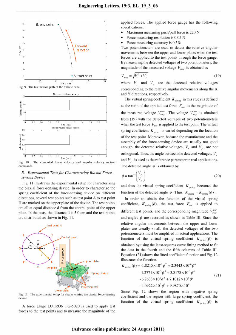
Fig. 9. The test motion path of the robotic cane.
Fig. 10. The computed linear velocity and angular velocity motion
commands.
B. Experimental Tests for Characterizing Biaxial Force-
sensing Device
Fig. 11 illustrates the experimental setup for characterizing
the biaxial force-sensing device. In order to characterize the
spring coefficient of the force-sensing device on different
directions, several test points such as test point A to test point
H are marked on the upper plate of the device. The test points
are all at equal distance d from the central point of the upper
plate. In the tests, the distance d is 5.0 cm and the test points
are distributed as shown in Fig. 11.
Fig. 11. The experimental setup for characterizing the biaxial force-sensing
device.
A force gauge LUTRON FG-5020 is used to apply test
forces to the test points and to measure the magnitude of the
applied forces. The applied force gauge has the following
specifications:
• Maximum measuring push/pull force is 220 N
• Force measuring resolution is 0.05 N
• Force measuring accuracy is 0.5%
Two potentiometers are used to detect the relative angular
movements between the upper and lower plates when the test
forces are applied to the test points through the force gauge.
By measuring the detected voltages of two potentiometers, the
magnitude of the measured voltage magV is obtained as
22
yxmag VVV += (19)
where xV and yV are the detected relative voltages
corresponding to the relative angular movements along the X
and Y directions, respectively.
The virtual spring coefficient springK in this study is defined
as the ratio of the applied test force testF to the magnitude of
the measured voltage test
magV . The voltage test
magV is obtained
from (19) with the detected voltages of two potentiometers
when the test force testF is applied to the test point. The virtual
spring coefficient springK is varied depending on the location
of the test point. Moreover, because the manufacture and the
assembly of the force-sensing device are usually not good
enough, the detected relative voltages, xV and yV , are not
orthogonal. Thus, the angle between the detected voltages, xV
and yV , is used as the reference parameter in real applications.
The detected angle φ is obtained by
= −
x
y
V
V1tanφ (20)
and thus the virtual spring coefficient springK becomes the
function of the detected angle φ . Thus, )(φspringspring KK = .
In order to obtain the function of the virtual spring
coefficient, )(φspringK , the test force testF is applied to
different test points, and the corresponding magnitude test
magV
and angles φ are recorded as shown in Table III. Since the
relative angular movements between the upper and lower
plates are usually small, the detected voltages of the two
potentiometers must be amplified in actual applications. The
function of the virtual spring coefficient )(φspringK is
obtained by using the least-squares curve fitting method to fit
the data in the fourth and the fifth columns of Table III.
Equation (21) shows the fitted coefficient function and Fig. 12
illustrates the function.
615
2331
41-53-
6-67-9
109.9870104.0922-
107.1012106.7633-
103.8178101.2771-
102.344310-1.8215)(
×+×
×+×
×+×
×+×=
φ
φφ
φφ
φφφspringK
(21)
Since Fig. 12 shows the region with negative spring
coefficient and the region with large spring coefficient, the
function of the virtual spring coefficient )(φspringK is
Engineering Letters, 19:3, EL_19_3_06
(Advance online publication: 24 August 2011)
______________________________________________________________________________________

modified as shown in (22) for providing safe motions of the
robotic cane.
<
≥
=
×+×
×+×
×+×
×+×=
otherwise ),(ˆ
0)(ˆ ,0
)(ˆ ,
)(
109.9870104.0922-
107.1012106.7633-
103.8178101.2771-
102.344310-1.8215)(ˆ
615
2331
41-53-
6-67-9
φ
φ
φ
φ
φ
φφ
φφ
φφφ
spring
spring
upper
springspring
upper
spring
spring
spring
K
K
KKK
K
K
(22)
In (22), the upper limit upper
springK is designed by experiments,
and it is 600.0 N/Volt in this study.
Since relative angular movements between the upper and
lower plates occur when the user’s hand exerts forces on the
force-sensing device, the magnitude of the measured voltage
magV can be obtained by (19), and the detected angle φ can be
obtained by (20). The virtual spring coefficient )(φspringK can
be obtained by (22). In this study, the equivalent force appF
used to control the mobile platform of the robotic cane is
obtained as
magspringapp VKF ⋅= )(φ (23)
Moreover, in this study, the detected angle φ shown in (20) is
used to select the motion path of the robotic cane, as shown in
Fig. 5 and Table II. If the detect angle generated due to the
operation of user’s hand is near the detect angle of a test point,
as shown in Table III, the sub-range corresponding to the test
point, as shown in Fig. 5, is used to select the motion path
according to Table II. For instance, if the detect angle
generated due to the operation of user’s hand is near the
detected angle of test point A, the sub-range “R3” is used to
select the motion path “Path F” for the robotic cane.
Fig. 12. The function of the virtual spring coefficient.
TABLE III
EXPERIMENTAL RESULTS OF THE BIAXIAL FORCE-SENSING DEVICE
Test
point
Test force
testF (N)
Detected
magnitude
test
magV (Volt)
Detected
angle
φ (Degree)
Virtual spring
coefficient
springK (N/Volt)
A 210.65 1.13 132.51 184.85
B 184.55 0.31 116.56 589.52
C 196.05 0.70 143.13 280.00
D 152.50 0.28 255.96 528.38
E 197.45 0.44 251.56 445.99
F 160.55 0.84 184.76 190.47
G 190.15 1.68 175.23 112.79
H 180.20 1.79 159.44 100.43
C. Autonomous Motion Mode (AMM) Tests
Figs. 13–17 show the experimental results when the robotic
cane executes the AMM mode. The desired linear velocity is
10.0 cm/s. As shown in Figs. 13 and 14, although the force-
sensing device equipped on the robotic cane detects the forces
exerted by the user’s hand, the robotic cane still executes the
desired motion according to the desired linear velocity.
However, as shown in Figs. 15–17, the motion of the robotic
cane changes according to the status of the applied infrared
range sensors. The robotic cane turns to the left with a positive
angular velocity, as shown in Fig. 16, when the right infrared
range sensor detects obstacles on the front-right side of the
robotic cane, as shown in Fig. 17; the robotic cane turns to the
right with negative angular velocity when the left infrared
range sensor detects obstacles on the front-left side of the
robotic cane. The linear velocity response exhibits fluctuation,
as shown in Fig. 15, because the selected motion paths of the
robotic cane periodically change according to the status of the
applied range sensors.
Fig. 13. Linear velocity response of the robotic cane (AMM mode).
Engineering Letters, 19:3, EL_19_3_06
(Advance online publication: 24 August 2011)
______________________________________________________________________________________
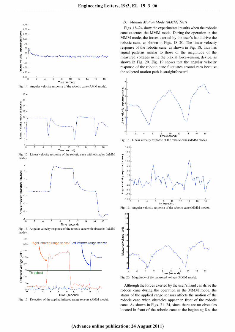
Fig. 14. Angular velocity response of the robotic cane (AMM mode).
Fig. 15. Linear velocity response of the robotic cane with obstacles (AMM
mode).
Fig. 16. Angular velocity response of the robotic cane with obstacles (AMM
mode).
Fig. 17. Detection of the applied infrared range sensors (AMM mode).
D. Manual Motion Mode (MMM) Tests
Figs. 18–24 show the experimental results when the robotic
cane executes the MMM mode. During the operation in the
MMM mode, the forces exerted by the user’s hand drive the
robotic cane, as shown in Figs. 18–20. The linear velocity
response of the robotic cane, as shown in Fig. 18, thus has
signal patterns similar to those of the magnitude of the
measured voltages using the biaxial force-sensing device, as
shown in Fig. 20. Fig. 19 shows that the angular velocity
response of the robotic cane fluctuates around zero because
the selected motion path is straightforward.
Fig. 18. Linear velocity response of the robotic cane (MMM mode).
Fig. 19. Angular velocity response of the robotic cane (MMM mode).
Fig. 20. Magnitude of the measured voltage (MMM mode).
Although the forces exerted by the user’s hand can drive the
robotic cane during the operation in the MMM mode, the
status of the applied range sensors affects the motion of the
robotic cane when obstacles appear in front of the robotic
cane. As shown in Figs. 21–24, since there are no obstacles
located in front of the robotic cane at the beginning 8 s, the
Engineering Letters, 19:3, EL_19_3_06
(Advance online publication: 24 August 2011)
______________________________________________________________________________________
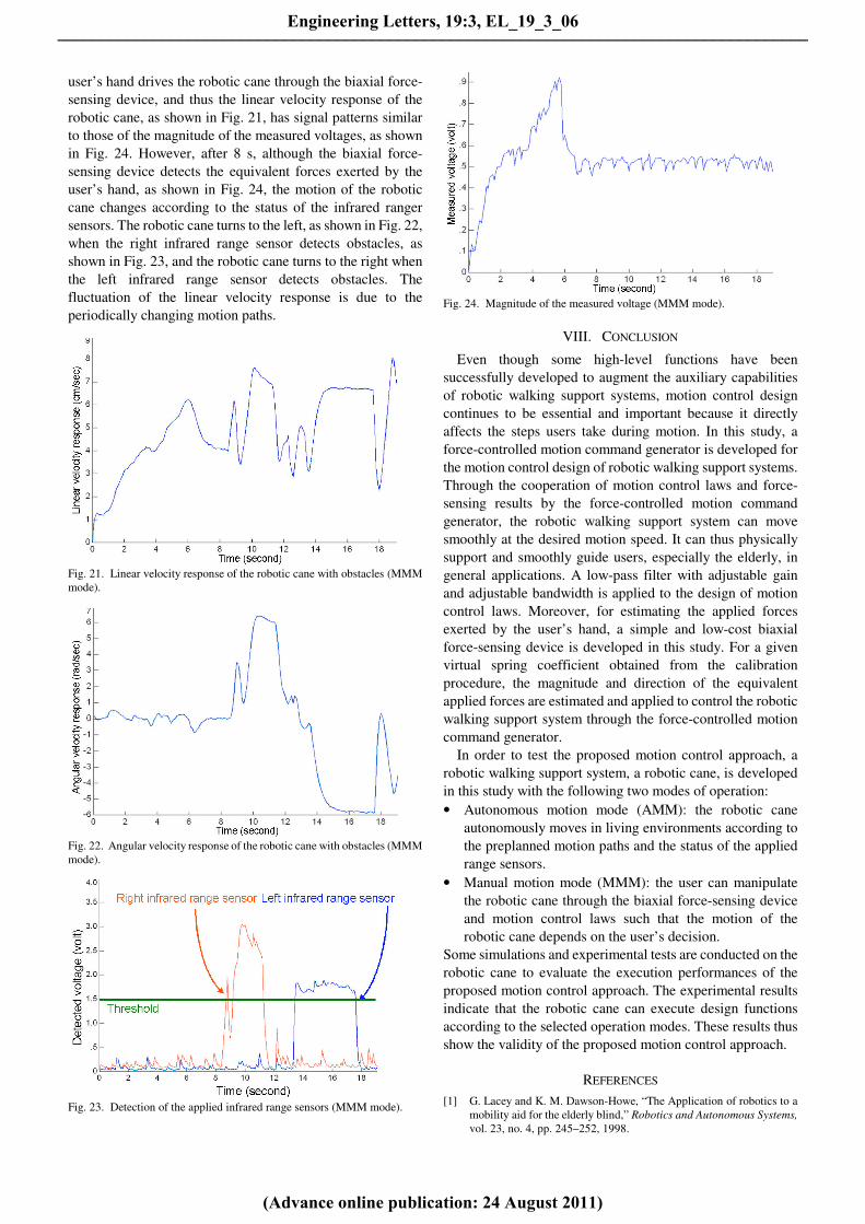
user’s hand drives the robotic cane through the biaxial force-
sensing device, and thus the linear velocity response of the
robotic cane, as shown in Fig. 21, has signal patterns similar
to those of the magnitude of the measured voltages, as shown
in Fig. 24. However, after 8 s, although the biaxial force-
sensing device detects the equivalent forces exerted by the
user’s hand, as shown in Fig. 24, the motion of the robotic
cane changes according to the status of the infrared ranger
sensors. The robotic cane turns to the left, as shown in Fig. 22,
when the right infrared range sensor detects obstacles, as
shown in Fig. 23, and the robotic cane turns to the right when
the left infrared range sensor detects obstacles. The
fluctuation of the linear velocity response is due to the
periodically changing motion paths.
Fig. 21. Linear velocity response of the robotic cane with obstacles (MMM
mode).
Fig. 22. Angular velocity response of the robotic cane with obstacles (MMM
mode).
Fig. 23. Detection of the applied infrared range sensors (MMM mode).
Fig. 24. Magnitude of the measured voltage (MMM mode).
VIII. CONCLUSION
Even though some high-level functions have been
successfully developed to augment the auxiliary capabilities
of robotic walking support systems, motion control design
continues to be essential and important because it directly
affects the steps users take during motion. In this study, a
force-controlled motion command generator is developed for
the motion control design of robotic walking support systems.
Through the cooperation of motion control laws and force-
sensing results by the force-controlled motion command
generator, the robotic walking support system can move
smoothly at the desired motion speed. It can thus physically
support and smoothly guide users, especially the elderly, in
general applications. A low-pass filter with adjustable gain
and adjustable bandwidth is applied to the design of motion
control laws. Moreover, for estimating the applied forces
exerted by the user’s hand, a simple and low-cost biaxial
force-sensing device is developed in this study. For a given
virtual spring coefficient obtained from the calibration
procedure, the magnitude and direction of the equivalent
applied forces are estimated and applied to control the robotic
walking support system through the force-controlled motion
command generator.
In order to test the proposed motion control approach, a
robotic walking support system, a robotic cane, is developed
in this study with the following two modes of operation:
• Autonomous motion mode (AMM): the robotic cane
autonomously moves in living environments according to
the preplanned motion paths and the status of the applied
range sensors.
• Manual motion mode (MMM): the user can manipulate
the robotic cane through the biaxial force-sensing device
and motion control laws such that the motion of the
robotic cane depends on the user’s decision.
Some simulations and experimental tests are conducted on the
robotic cane to evaluate the execution performances of the
proposed motion control approach. The experimental results
indicate that the robotic cane can execute design functions
according to the selected operation modes. These results thus
show the validity of the proposed motion control approach.
REFERENCES
[1] G. Lacey and K. M. Dawson-Howe, “The Application of robotics to a
mobility aid for the elderly blind,” Robotics and Autonomous Systems,
vol. 23, no. 4, pp. 245–252, 1998.
Engineering Letters, 19:3, EL_19_3_06
(Advance online publication: 24 August 2011)
______________________________________________________________________________________

[2] S. MacNamara and G. Lacey, “A Smart walker for the frail visually
impaired,” Proc. of the 2000 IEEE International Conference on
Robotics and Automation, vol. 2, pp. 1354–1359, 2000.
[3] B. Graf, M. Hans, and R. D. Schraft, “Care-O-bot II - Development of a
Next Generation Robotic Home Assistant,” Autonomous Robots, vol.
16, no. 2, pp. 193–205, 2004.
[4] Y. Hirata, A. Hara, and K. Kosuge, “Motion control of passive
intelligent walker using servo brakes,” IEEE Transactions on Robotics,
vol. 23, no. 5, pp. 981–990, 2007.
[5] O. Chuy Jr., Y. Hirata, and K. Kosuge, “Online approach in adapting
user characteristic for robotic walker control,” Proc. of the 2005 IEEE
9th International Conference on Rehabilitation Robotics, vol. 2005,
pp. 139–142, 2005.
[6] O. Chuy Jr., Y. Hirata, and K. Kosuge, “A new control approach for a
robotic walking support system in adapting user characteristics,” IEEE
Transactions on Systems, Man and Cybernetics Part C: Applications
and Reviews, vol. 36, no. 6, pp. 725–733, 2006.
[7] O. Chuy Jr., Y. Hirata, Z. Wang, and K. Kosuge, “A control approach
based on passive behavior to enhance user interaction,” IEEE
Transactions on Robotics, vol. 23, no. 5, pp. 899–908, 2007.
[8] G. Wasson, P. Sheth, M. Alwan, K. Granata, A. Ledoux, and C. Huang,
“User Intent in a Shared Control Framework for Pedestrian Mobility
Aids,” Proc. of the 2003 IEEE International Conference on Intelligent
Robots and Systems, vol. 3, pp. 2962–2967, 2003.
[9] A. Morris, R. Donamukkala, A. Kapuria, A. Steinfeld, J. T. Matthews,
J. Dunbar-Jacob, and S. Thrun, “A robotic walker that provides
guidance,” Proc. of the 2003 IEEE International Conference on
Robotics and Automation, vol. 1, pp. 25–30, 2003.
[10] A. M. Sabatini, V. Genovese, and E. Pacchierotti, “A mobility aid for
the support to walking and object transportation of people with motor
impairments,” Proc. of the 2002 IEEE International Conference on
Intelligent Robots and Systems, vol. 2, pp. 1349–1354, 2002.
[11] M. Spenko, H. Yu, S. Dubowsky, “Robotic personal aids for mobility
and monitoring for the elderly,” IEEE Transactions on Neural Systems
and Rehabilitation Engineering, vol. 14, no. 3, pp. 344–351, 2006.
[12] M.-J. Yoon, K.-H. Yu, J.-H. Kang, and N.-G. Kim, “Walking guide
robot with tactile display for the blind,” Proc. of the SPIE - The
International Society for Optical Engineering, vol. 6040, ICMIT 2005:
Mechatronics, MEMS and Smart Materials, pp. 60402A, 2005.
[13] I. Shim, J. Yoon, and M. Yoh, “A human robot interactive system
‘RoJi’,” International Journal of Control, Automation and Systems,
vol. 2, no. 3, pp. 398–405, 2004.
[14] S. Shoval, I. Ulrich, and J. Borenstein, “Robotics-Based Obstacle-
Avoidance Systems for the Blind and Visually Impaired: NavBelt and
the GuideCane,” IEEE Robotics and Automation Magazine, vol. 10,
no. 1, pp. 9–20, 2003.
[15] P. Aigner and B. McCarragher, “Shared control framework applied to a
robotic aid for the blind,” Proc. of the 1998 IEEE International
Conference on Robotics and Automation, vol. 1, pp. 717–722, 1998.
[16] Y. Z. Zhang and S. S. Yeh, “Motion Control Design for Robotic
Walking Support Systems Using Admittance Motion Command
Generator,” Lecture Notes in Engineering and Computer Science:
Proc. of The International MultiConference of Engineers and
Computer Scientists 2011, vol. 2, pp. 781-786, 2011.
Engineering Letters, 19:3, EL_19_3_06
(Advance online publication: 24 August 2011)
______________________________________________________________________________________