Embed Size (px)
Citation preview
Motion Capture using Body Mounted Cameras in an Unknown Environment
Nam Vo Taeyoung Kim Siddharth Choudhary
1. The Problem
Motion capture has been recently used to provide muchof character motion in several recent theatrical releases. Itgenerally requires the recording to be done in an indoor en-vironment with controlled light setting. This prevents di-rectors from capturing motion in a natural setting or a largeenvironment. In this paper we propose a method to solvethis problem of motion capture in an unknown and uncon-strained environment by using body mounted cameras.
2. Related work
Motion capture technology has been studied for a longtime [7]. The technology is also available as commercialproducts from Vicon and Qualisys [1, 2]. Most of these ap-proaches are classified as outside-in as they require sensorsmounted in an environment. In contrast our approach is aninside-out approach and uses the cameras mounted on thebody to recover the motion.
Markerless motion capture techniques has been devel-oped by a number of researchers [3, 4]. More recently,Hasler et al. proposed a method to handle markerless mo-tion capture using structure from motion to handle registercameras with respect to the background and using conven-tional motion capture to estimate the motion of the artic-ulated object [4]. Our work is the most closely related tothe work by Shiratori et al. which also tries to capture mo-tion using body mounted cameras[5]. However they requirea known environment which is reconstructed using the ref-erence images prior to running their algorithm. We haveno such requirement. Our approach is also fundamentallydifferent from most of these approaches as we propose aninside-out system.
3. Approach
Unlike [5], our hardware setup is simpler: we use a setof 3 cheap webcams which are attached to torso and hands.All webcams are connected to a single computer to recordvideos. However our approach is supposed to work withany number of cameras as long as synchronized videos aregiven as input. The system consists of 2 main parts: 3Dreconstruction and skeleton estimation.
3.1. 3D Reconstruction
For the 3D reconstruction step, we apply traditionalstructure from motion technique to build a sparse model ofthe environment. At the same time, each camera’s pose isalso retrieved and represent initial guess for correspondingbody part position.
Initialize Model: First of all, we initialize the model us-ing some images. This is done off-line on some framesfrom all cameras. First, SIFT features are extracted and cor-respondences between pairs of images that has significantnumber of matches are estimated using RANSAC. Next,we triangulate location of matched features points in 3D.The set of points and cameras are optimized using GTSAM.Some of the triangulated points having reprojection errorgreater than some threshold are removed from the set. Asa result, we get an initial model consisting of camera andpoints.
Feature Tracking: Given a set of reconstructed imagesand points, we track the features in rest of the frames usingKanade Lucas Tomasi (KLT) feature tracker. Using the KLTtracker, we create a mapping between already reconstructedpoints and the features found in new frames. The factors be-tween new frames and the existing points are added to factorgraph which is used to optimize its pose with respect to theworld. We do not triangulate any new points in the trackingstage. In case tracking fails due to lack of correspondencesbetween existing 3D points and 2D features, we reconstructanother frame using incremental reconstruction.
Incremental Reconstruction: Whenever tracking fails,we match the current frame to the previous five frames andgrow the 3D model by incrementally adding points and im-ages using their correspondences to the existing model. Themodel is again optimized using GTSAM over the newlyadded points and images and all the previously trackedframes to minimize the error introduced by tracking. Asthe result, we have new 3D points and camera poses whichis used to track rest of the frames until it again fails. As thesystem progresses, the drifting error of individual cameraswould make the skeleton more and more inconsistent. Sothe final step in the pipeline is to do global optimization to
1
solve for optimal skeleton. Algorithm 1 gives the completealgorithm.
Algorithm 1 3D ReconstructionInitialize Modelrepeat
Track features with respect to the modelif tracking fails then
Do incremental reconstruction and optimizeend if
until end of the sequence
3.2. Skeleton Estimation
In addition, we make use of the fact that there are con-straints between cameras, for example relative pose be-tween the camera attached to torso is unlikely to changeovertime, so they can be calibrated in advance. The camerasattached to the torso and the palm is restricted by the intro-duction of distance constraint between the cameras. Sincewe found only three cameras, we cannot model the addi-tional degree of freedom available in human motion. Otherthan this, we also restrict human motion to walk-only mo-tion. For generic activities we do not have any constraint onthe palm motion and palm can reach anywhere within somedistance to the torso. In implementation we create a factorbetween the poses of torso and hand and optimize over theposes and the structure together.
4. EvaluationAs there is no standard dataset for this line of ap-
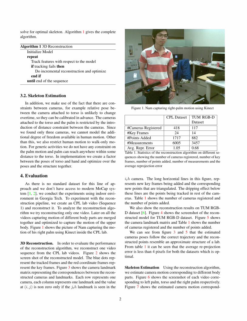
proach and we don’t have access to modern MoCap sys-tem [1, 2], we conduct the experiments using indoor envi-ronment in Georgia Tech. To experiment with the recon-struction pipeline, we create an CPL lab video (Sequence1) and reconstruct it. To analyze the reconstruction algo-rithm we try reconstructing only one video. Later on all thevideos capturing motion of different body parts are mergedtogether and optimized to capture the motion of the upperbody. Figure 1 shows the picture of Nam capturing the mo-tion of his right palm using Kinect inside the CPL lab.
3D Reconstruction. In order to evaluate the performanceof the reconstruction algorithm, we reconstruct one videosequence from the CPL lab videos. Figure 2 shows thescreen shot of the reconstructed model. The blue dots rep-resent the tracked frames and the red coordinate frames rep-resent the key frames. Figure 3 shows the camera landmarkmatrix representing the correspondences between the recon-structed cameras and landmarks. Each row represents onecamera, each column represents one landmark and the valueat (i, j) is non zero only if the jth landmark is seen in the
Figure 1. Nam capturing right-palm motion using Kinect
CPL Dataset TUM RGB-DDataset
#Cameras Registered 418 117#Key Frames 24 14#Points Added 1717 882#Measurements 6005 3457Avg. Repr. Error 1.05 0.68
Table 1. Statistics of the reconstruction algorithm on different se-quences showing the number of cameras registered, number of keyframes, number of points added, number of measurements and theaverage reprojection error
ith camera. The long horizontal lines in this figure, rep-resents new key frames being added and the correspondingnew points that are triangulated. The dripping effect belowthese lines are the points being tracked in rest of the cam-eras. Table 1 shows the number of cameras registered andthe number of points added.
We also show the reconstruction results on TUM RGB-D dataset [6]. Figure 4 shows the screenshot of the recon-structed model for TUM RGB-D dataset. Figure 5 showsthe camera landmark matrix and Table 1 shows the numberof cameras registered and the number of points added.
We can see from figure 3 and 5 that the estimatedcameras poses follow the correct trajectory and the recon-structed points resemble an approximate structure of a lab.From table 1 it can be seen that the average re-projectionerror is less than 4 pixels for both the datasets which is op-timal.
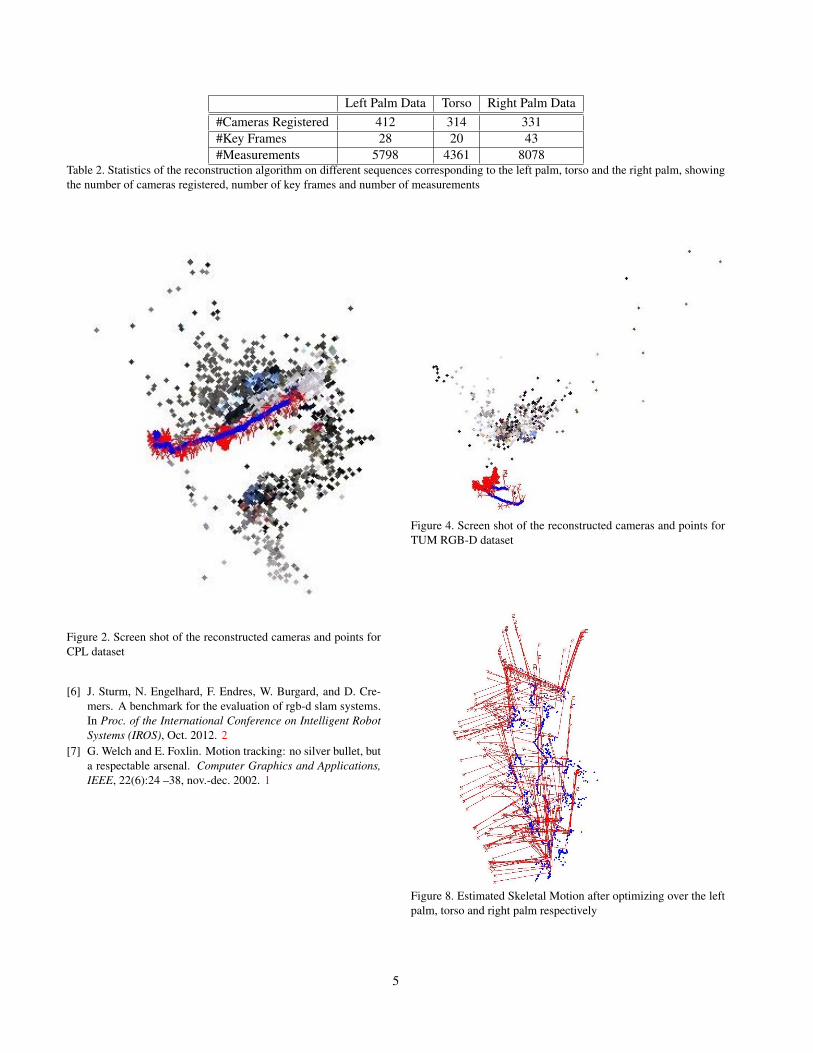
Skeleton Estimation Using the reconstruction algorithm,we estimate camera motion corresponding to different bodyparts. Figure 6 shows the screenshot of each video corre-sponding to left palm, torso and the right palm respectively.Figure 7 shows the estimated camera motion correspond-
2
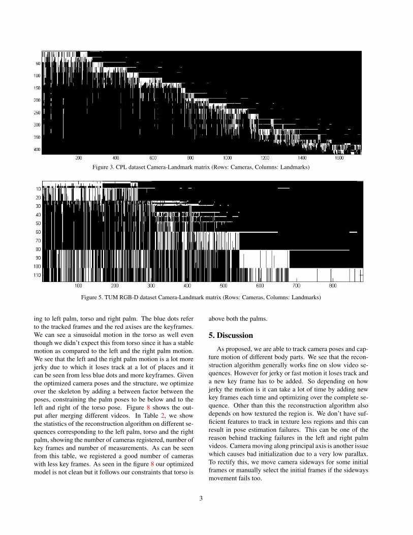
Figure 3. CPL dataset Camera-Landmark matrix (Rows: Cameras, Columns: Landmarks)
Figure 5. TUM RGB-D dataset Camera-Landmark matrix (Rows: Cameras, Columns: Landmarks)
ing to left palm, torso and right palm. The blue dots referto the tracked frames and the red axises are the keyframes.We can see a sinusoidal motion in the torso as well eventhough we didn’t expect this from torso since it has a stablemotion as compared to the left and the right palm motion.We see that the left and the right palm motion is a lot morejerky due to which it loses track at a lot of places and itcan be seen from less blue dots and more keyframes. Giventhe optimized camera poses and the structure, we optimizeover the skeleton by adding a between factor between theposes, constraining the palm poses to be below and to theleft and right of the torso pose. Figure 8 shows the out-put after merging different videos. In Table 2, we showthe statistics of the reconstruction algorithm on different se-quences corresponding to the left palm, torso and the rightpalm, showing the number of cameras registered, number ofkey frames and number of measurements. As can be seenfrom this table, we registered a good number of cameraswith less key frames. As seen in the figure 8 our optimizedmodel is not clean but it follows our constraints that torso is
above both the palms.
5. DiscussionAs proposed, we are able to track camera poses and cap-
ture motion of different body parts. We see that the recon-struction algorithm generally works fine on slow video se-quences. However for jerky or fast motion it loses track anda new key frame has to be added. So depending on howjerky the motion is it can take a lot of time by adding newkey frames each time and optimizing over the complete se-quence. Other than this the reconstruction algorithm alsodepends on how textured the region is. We don’t have suf-ficient features to track in texture less regions and this canresult in pose estimation failures. This can be one of thereason behind tracking failures in the left and right palmvideos. Camera moving along principal axis is another issuewhich causes bad initialization due to a very low parallax.To rectify this, we move camera sideways for some initialframes or manually select the initial frames if the sidewaysmovement fails too.
3
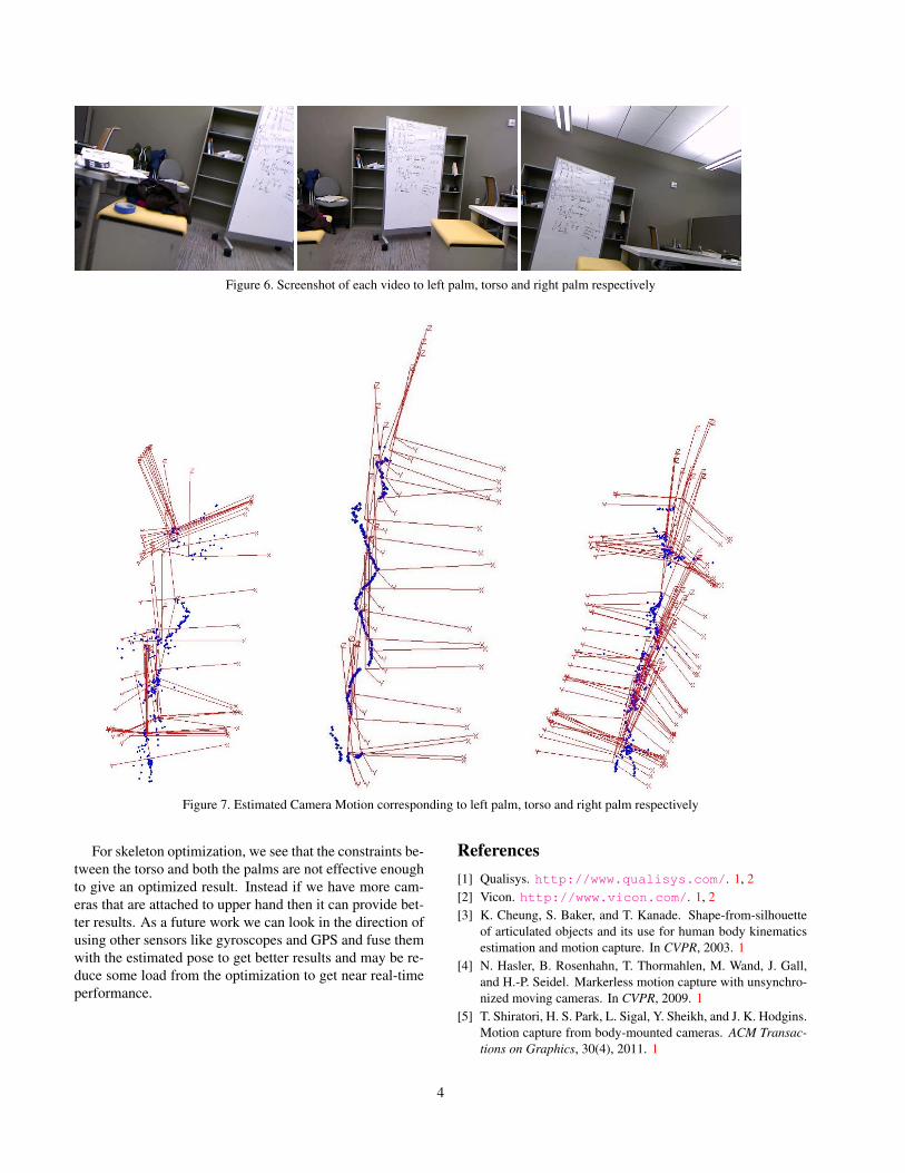
Figure 6. Screenshot of each video to left palm, torso and right palm respectively
Figure 7. Estimated Camera Motion corresponding to left palm, torso and right palm respectively
For skeleton optimization, we see that the constraints be-tween the torso and both the palms are not effective enoughto give an optimized result. Instead if we have more cam-eras that are attached to upper hand then it can provide bet-ter results. As a future work we can look in the direction ofusing other sensors like gyroscopes and GPS and fuse themwith the estimated pose to get better results and may be re-duce some load from the optimization to get near real-timeperformance.
References[1] Qualisys. http://www.qualisys.com/. 1, 2[2] Vicon. http://www.vicon.com/. 1, 2[3] K. Cheung, S. Baker, and T. Kanade. Shape-from-silhouette
of articulated objects and its use for human body kinematicsestimation and motion capture. In CVPR, 2003. 1
[4] N. Hasler, B. Rosenhahn, T. Thormahlen, M. Wand, J. Gall,and H.-P. Seidel. Markerless motion capture with unsynchro-nized moving cameras. In CVPR, 2009. 1
[5] T. Shiratori, H. S. Park, L. Sigal, Y. Sheikh, and J. K. Hodgins.Motion capture from body-mounted cameras. ACM Transac-tions on Graphics, 30(4), 2011. 1
4
Left Palm Data Torso Right Palm Data#Cameras Registered 412 314 331#Key Frames 28 20 43#Measurements 5798 4361 8078
Table 2. Statistics of the reconstruction algorithm on different sequences corresponding to the left palm, torso and the right palm, showingthe number of cameras registered, number of key frames and number of measurements
Figure 2. Screen shot of the reconstructed cameras and points forCPL dataset
[6] J. Sturm, N. Engelhard, F. Endres, W. Burgard, and D. Cre-mers. A benchmark for the evaluation of rgb-d slam systems.In Proc. of the International Conference on Intelligent RobotSystems (IROS), Oct. 2012. 2
[7] G. Welch and E. Foxlin. Motion tracking: no silver bullet, buta respectable arsenal. Computer Graphics and Applications,IEEE, 22(6):24 –38, nov.-dec. 2002. 1
Figure 4. Screen shot of the reconstructed cameras and points forTUM RGB-D dataset
Figure 8. Estimated Skeletal Motion after optimizing over the leftpalm, torso and right palm respectively
5


![When Cameras Are Rolling: Privacy Implications of Body- Mounted …jlsp.law.columbia.edu/wp-content/uploads/sites/8/2017/03/49-Freund.pdf · 2015] When Cameras are Rolling 93 . In](https://img.pdfslide.us/doc/110x75/5bc459f609d3f2f75b8b8a21/when-cameras-are-rolling-privacy-implications-of-body-mounted-jlsplaw-2015.jpg)