Embed Size (px)
Citation preview
Motherboards and expansion cards
Unit objective: Identify motherboard components and
install expansion cards
Topic A
Topic A: Safety procedures Topic B: Motherboards Topic C: BIOS settings Topic D: Expansion cards
Electrostatic discharge (ESD)
Buildup of charges Static dangers Discharge voltages
– 3000+ volts to feel– 8000+ volts to see spark– 35,000 volts on a dry day on carpet– 30 volts can damage electronics
Preventing static buildup
Don’t shuffle your feet Increase the humidity: 50-60% Keep yourself grounded Wear cotton, not synthetics Remove carpeting Use air ionization system
Preventing static discharge
Equalize charge differences safely– Unplug the equipment– Touch the metal chassis or power supply
Keep yourself and equipment connected together– Wrist straps and antistatic mats– Static-safe bags
Goal is to be at a charge potential that’s equal with the device you’re servicing (not with ground)
Service on a properly grounded bench
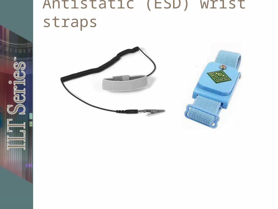
Antistatic (ESD) wrist straps
Inside the case
Typical internal components Opening the case Front cover
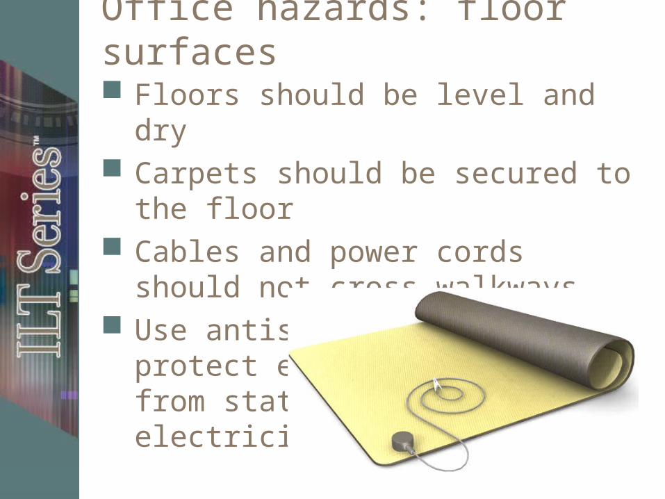
Office hazards: floor surfaces
Floors should be level and dry Carpets should be secured to the floor Cables and power cords should not
cross walkways Use antistatic mats to protect
equipment from static electricity
Office hazards: fire safety
Keep papers orderly – In metal file cabinet when possible
Keep combustibles away from coffee pots, hot plates, personal heaters
Keep working smoke detectors in all areas of building
Keep fire extinguishers readily available for each type of equipment you have
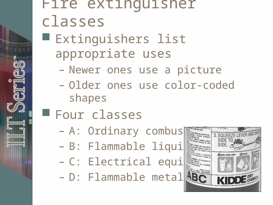
Fire extinguisher classes
Extinguishers list appropriate uses– Newer ones use a picture– Older ones use color-coded shapes
Four classes– A: Ordinary combustibles – B: Flammable liquids – C: Electrical equipment – D: Flammable metals

Fire extinguisher types
Dry chemicals Halon Water CO2
Office hazards: electrical safety
Don’t overload electrical circuits Label breakers in electrical box Use surge protectors and UPS Don’t string together power strips Don’t run electrical cords or network
cables across walkways Encase cords in a cord protector Provide good ventilation for equipment Secure cords out of the way
– Can use cable ties, but don’t cinch tightly
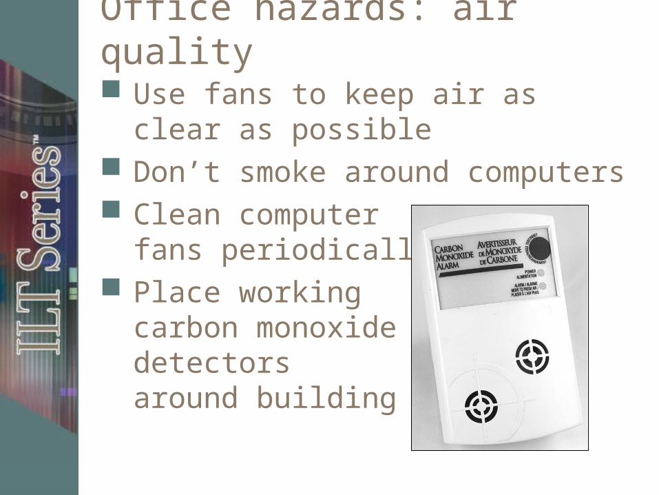
Office hazards: air quality
Use fans to keep air as clear as possible
Don’t smoke around computers Clean computer
fans periodically Place working
carbon monoxide detectors around building
Physical hazards
Use care when lifting and moving heavy or bulky equipment
When lifting, take a balanced stance Lift with leg muscles, not arms and back Keep back straight Grip with entire hand Bring equipment close to your body Keep the CRT screen towards body Make sure you can see where you’re going Restrain neckties, loose clothing, jewelry,
and long haircontinued
Physical hazards, continued
Heat:– Laptop burns– Internal components
Electrical hazards Use care when working with any electrical
equipment– Turn it off and unplug it, unless you don’t have
an ESD strap Inspect equipment wiring for defects Don’t use damaged or frayed electrical
cords Remove metal jewelry, watches, and rings
before working on equipment Do not allow any liquid near equipment Identify electrical ratings of equipment DON’T OPEN CRT unless specially trained
Laser printer and copier toner
Toner– Mixture of plastic resin, iron powder, and
carbon black– Particles are 10 microns or smaller– Can irritate respiratory tract – Can cause allergic skin reaction
Use facemask and gloves Clean up spills with special vacuum Recycle cartridges Replaceable ozone filters
Incident reporting
Company should have written policy– Handling accidents– Reporting incidents
Proper documentation required for OSHA, workmen’s comp claims, and insurance
Computer equipment disposal
Disposing of electronics– Hazardous materials
Disposing of used toner and ink cartridges
Disposing of computer equipment– Reusing equipment– Methods of disposal
Topic B
Topic A: Safety procedures Topic B: Motherboards Topic C: BIOS settings Topic D: Expansion cards

A motherboard
Back panel connectors
Socket 478 connector
3 DIMM banks
ATX power supply
2 IDE ports
Chipset
Chipset
Floppy drive port
CMOS battery
BIOS
AGP slot
CD-in connector (white line)
4 PCI slots
Motherboards
Components reviewCPU
Expansion slots
AGP graphics adapter slot
Hard drive interface connectors
Floppy drive interface connector
Optical drive interface connector
Power connector
Memory slots
PS/2 mouse and keyboard ports
USB port
IEEE 1394 / FireWire port
Serial port
Parallel port
CMOS battery
Network interface
Video connectors
Fan connectors
Jumpers
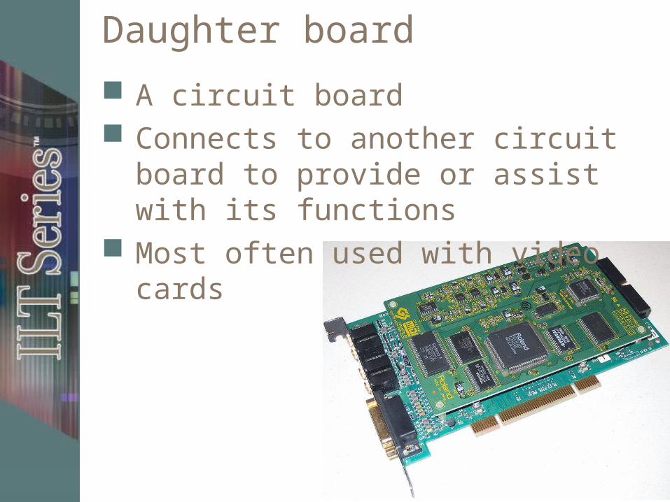
Daughter board
A circuit board Connects to another circuit board to
provide or assist with its functions Most often used with video cards
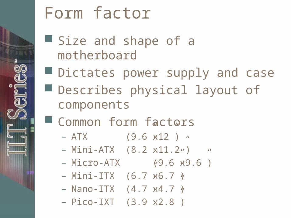
Form factor
Size and shape of a motherboard Dictates power supply and case Describes physical layout of
components Common form factors
– ATX (9.6”x12”)– Mini-ATX (8.2”x11.2”)– Micro-ATX (9.6”x9.6”)– Mini-ITX (6.7”x6.7”)– Nano-ITX (4.7”x4.7”)– Pico-IXT (3.9”x2.8”)
Computer bus
Communication pathway Defined by
– How many bits it transmits at one time– Signaling technique– Data transfer speed
Three types– Address – Transmits memory addresses– Data – Transfers data– Expansion (I/O) – Expansion cards
continued
Computer bus, continued
Address and data buses enable: – Basic CPU operation – Interactions with memory
Expansion bus– Communication pathway for non-core
components to interact with the CPU, memory, and other core components
– Adapter cards add functionality
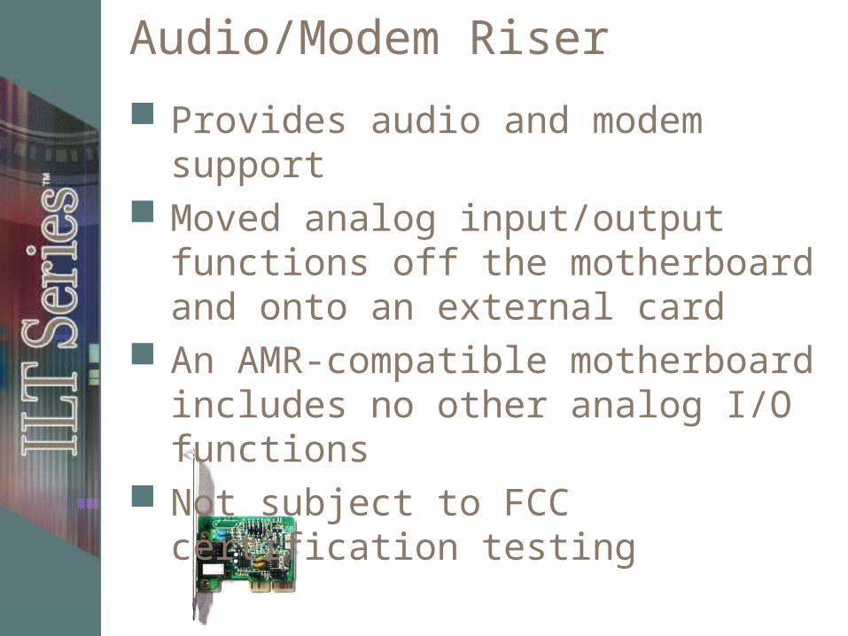
Audio/Modem Riser
Provides audio and modem support Moved analog input/output functions
off the motherboard and onto an external card
An AMR-compatible motherboard includes no other analog I/O functions
Not subject to FCC certification testing
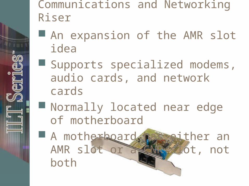
Communications and Networking Riser
An expansion of the AMR slot idea Supports specialized modems, audio
cards, and network cards Normally located near edge of
motherboard A motherboard has either an AMR slot
or a CNR slot, not both
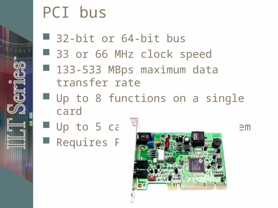
PCI bus
32-bit or 64-bit bus 33 or 66 MHz clock speed 133-533 MBps maximum data transfer rate Up to 8 functions on a single card Up to 5 cards/slots per system Requires PnP
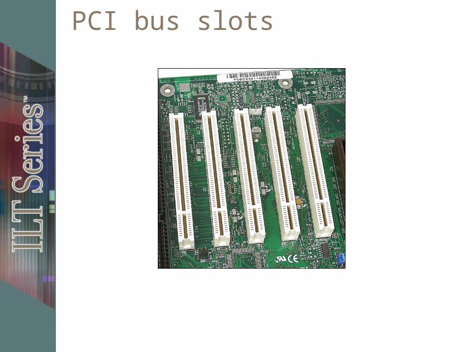
PCI bus slots
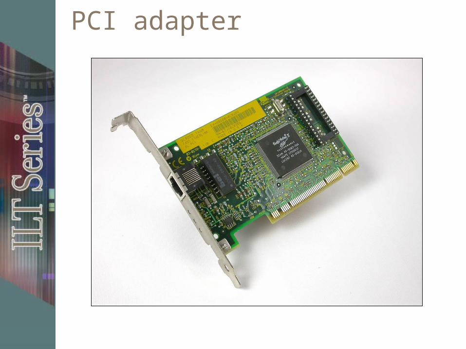
PCI adapter
PCI-X standard
Developed to address several shortcomings in the PCI standard
Increases bandwidth for high-performance components, running at 133 MHz and transferring up to a theoretical maximum of 1.06 Gpbs
PCI-X has been replaced in newer systems with the PCIe standard
PCIe
Newer standard Uses serial communication Lanes
– 2.5 Gbps in each direction using 8b/10b encoding (0.25 GBps)
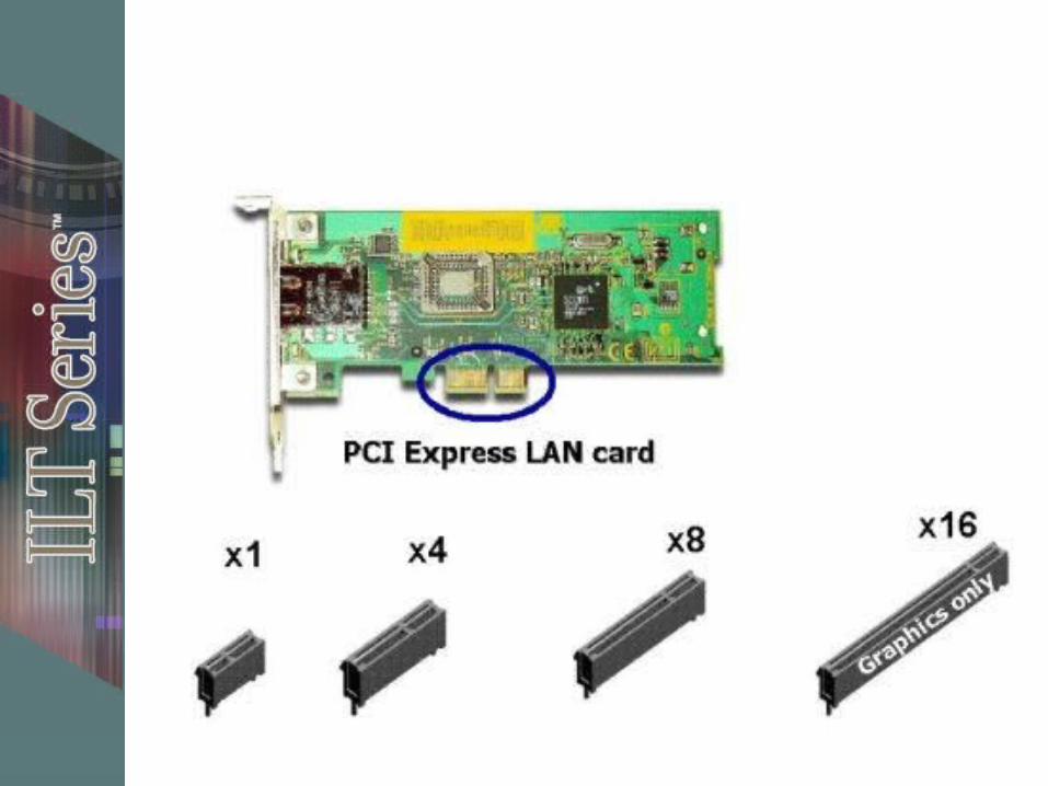
– x1 (by one), x2, x4, x8, x12, x16, and x32 bus widths
Links – bidirectional switched lanes Can up-plug (e.g., x1 card in x16 slot) Can’t down-plug (not officially)
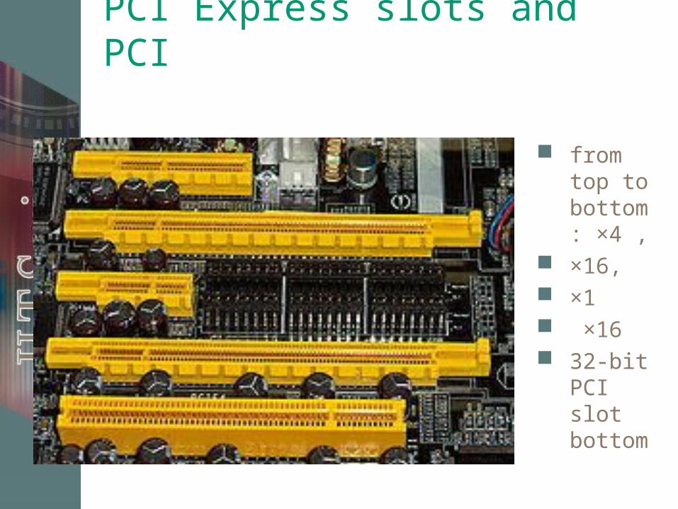
PCI Express slots and PCI
from top to bottom: ×4 ,
×16, ×1 ×16 32-bit
PCI slot bottom
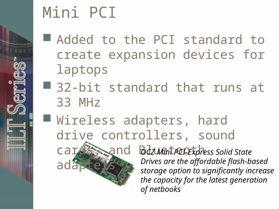
Mini PCI
Added to the PCI standard to create expansion devices for laptops
32-bit standard that runs at 33 MHz Wireless adapters, hard drive
controllers, sound cards, and Bluetooth adapters
OCZ Mini PCI-Express Solid State Drives are the affordable flash-based storage option to significantly increase the capacity for the latest generation of netbooks
AGP bus standard Standards – 1.0, 2.0, 3.0, 64-bit, Ultra, Pro,
Ultra II Technically a port, not a bus Provides direct connection between video
adapter and CPU Original performance benefit was accessing
and using main system memory– Direct Memory Execute (DIME)
Modern AGP cards use onboard memory, except in laptops
Multiple-monitor support Being phased out for PCIe
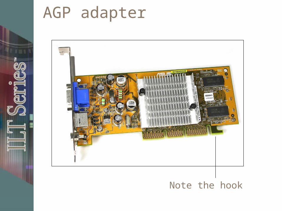
AGP adapter
Note the hook
AGP characteristics
Speeds referred to as #x Speed “pumped” to a multiple of
standard speed AGP 3.0 8x slot transfers data 8 times
per clock cycle– 8 times faster than clock speed– Maximum speed 2.13 GBps assuming a
clock rate of 533 MHz for the PCI bus
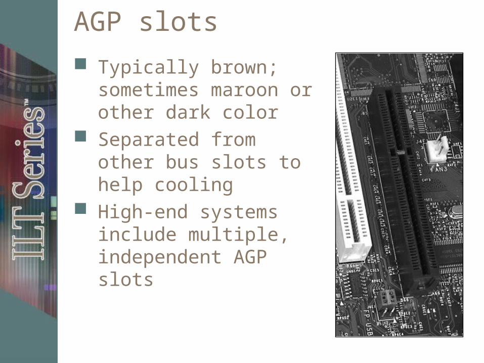
AGP slots
Typically brown; sometimes maroon or other dark color
Separated from other bus slots to help cooling
High-end systems include multiple, independent AGP slots
Multifunction cards
PCI spec supports multifunction cards Up to 8 functions per card Five slots/cards per system Total of 40 expansion devices
Chipsets
Memory control System bus functions Audio functions Video display functions System management functions
Northbridge and Southbridge
Two most important components of a PC chipset
Northbridge controls interactions between the CPU, memory (including cache), AGP and PCIe video control circuitry, and the Southbridge
Southbridge controls interactions between buses and devices not controlled by the Northbridge
Front panel connectors
Located on front of computer Includes
– USB– Audio– Power button– Power light– Drive activity lights– Reset button
Topic C
Topic A: Safety procedures Topic B: Motherboards Topic C: BIOS settings Topic D: Expansion cards
BIOS
Basic Input/Output System A set of software instructions stored
on a chip on the motherboard Enables basic computer functions
CMOS
Area of memory that stores BIOS configuration information
Type of computer chip: complementary metal oxide semiconductor
Can maintain information when system’s power is removed
BIOS configuration settings
Component information Configurable settings Monitoring BIOS configuration procedure
BIOS updates
BIOS implemented either in:– ROM: Programmed at factory (older technology)– Flash memory: Can update, “flash,” the BIOS
When to update Update sources Determining BIOS version Researching BIOS updates Flashing the BIOS
Topic D
Topic A: Safety procedures Topic B: Motherboards Topic C: BIOS settings Topic D: Expansion cards
Safe handling
Unplug your computer Work at anti-static workstation Ground yourself to the chassis Keep cards inside static-protective
bags Handle cards by their edges or slot
cover plate Don’t touch board components, traces,
or edge-connector pins
Drivers
Software that interacts with a device and enables its functions
Some are provided by operating system
Others you must install
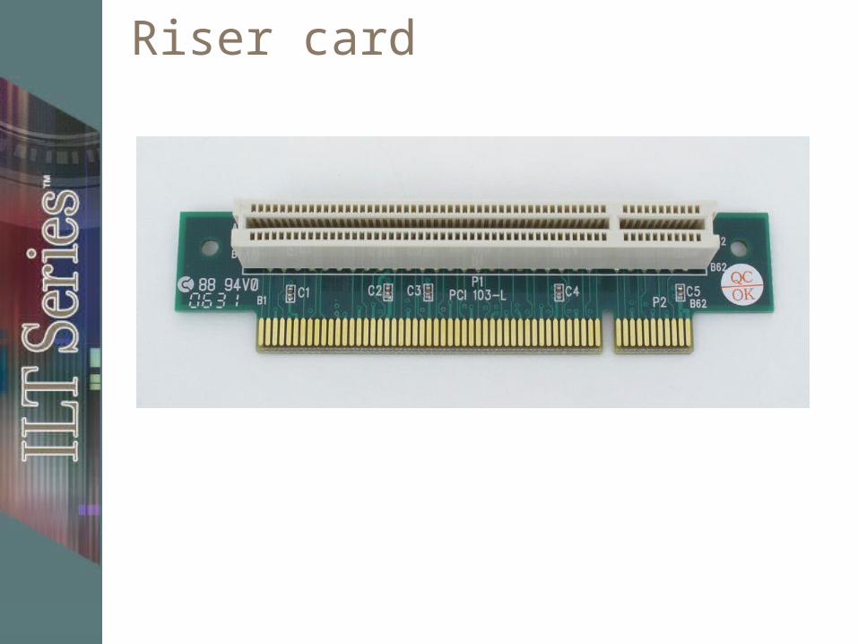
Riser card
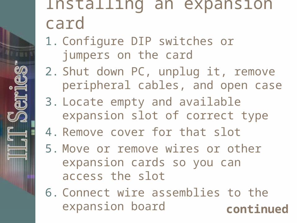
Installing an expansion card
1. Configure DIP switches or jumpers on the card
2. Shut down PC, unplug it, remove peripheral cables, and open case
3. Locate empty and available expansion slot of correct type
4. Remove cover for that slot
5. Move or remove wires or other expansion cards so you can access the slot
6. Connect wire assemblies to the expansion board
continued
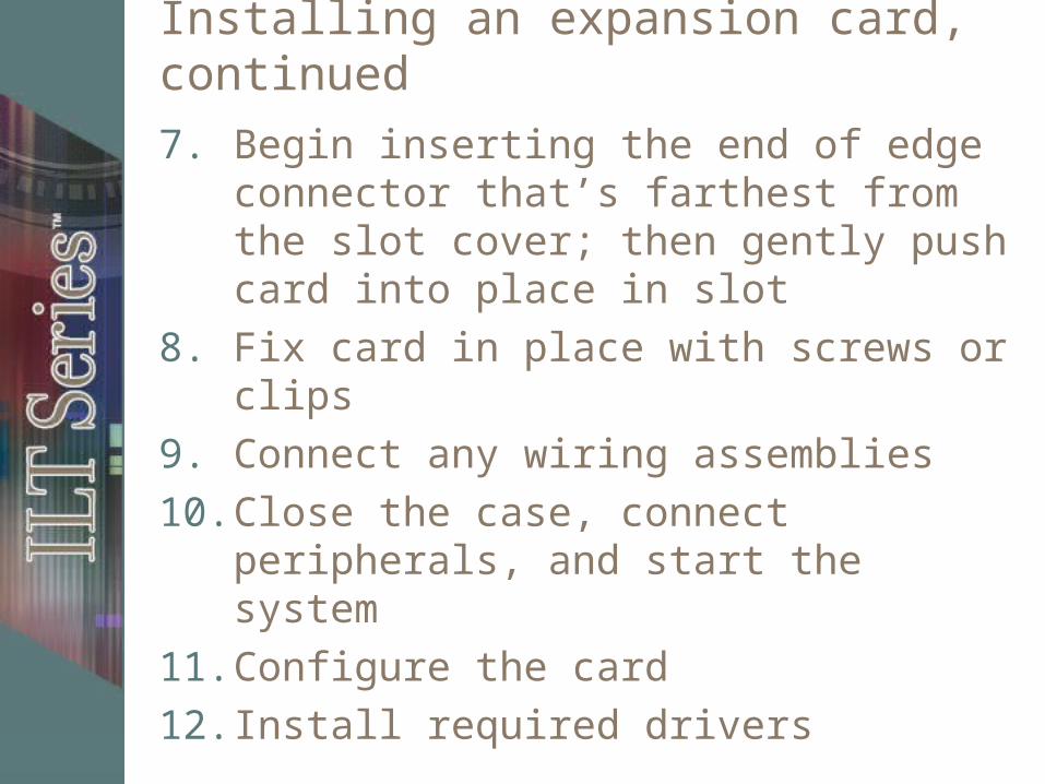
Installing an expansion card, continued
7. Begin inserting the end of edge connector that’s farthest from the slot cover; then gently push card into place in slot
8. Fix card in place with screws or clips
9. Connect any wiring assemblies
10. Close the case, connect peripherals, and start the system
11. Configure the card
12. Install required drivers
Video adapter slot types
Built into motherboard– Don’t take up an expansion slot– Common on low-end systems– Might be able to disable on-board video
adapter in BIOS
Three types of video expansion slots– PCI– AGP– PCIe
Installation of sound cards
Adapter card type must match expansion bus
Must attach CD drive’s audio-out cable to sound card
Some sound cards require device drivers from the manufacturer
Unit summary
Identified motherboard components and installed expansion cards