Embed Size (px)
Citation preview
A Subsidiary of
0
000
Most Widely Accepted and Trusted
ICC‐ES Report ESR‐2776Valid: 04/15 to 04/17
ICC‐ES | (800) 423‐6587 | (562) 699‐0543 | www.icc‐es.org
ICC-ES Evaluation Reports are not to be construed as representing aesthetics or any other attributes not specifically addressed, nor are they to be construed as an endorsement of the subject of the report or a recommendation for its use. There is no warranty by ICC Evaluation Service, LLC, express or implied, as to any finding or other matter in this report, or as to any product covered by the report.
Copyright © 2015
“2014 Recipient of Prestigious Western States Seismic Policy Council (WSSPC) Award in Excellence”
Look for the trusted marks of Conformity!
DIVISION: 05 00 00—METALS
SECTION: 05 05 23—METAL FASTENINGS
DIVISION: 05 31 00—STEEL DECKING
REPORT HOLDER:
HILTI, INC.
5400 SOUTH 122ND EAST AVENUE TULSA, OKLAHOMA 74146
EVALUATION SUBJECT:
STEEL DECK DIAPHRAGMS ATTACHED WITH HILTI X‐HSN 24, X‐EDNK22 THQ12,
X‐EDN19 THQ12 OR X‐ENP‐19 L15 POWDER‐DRIVEN FRAME FASTENERS
AND HILTI S‐SLC 01 M HWH OR S‐SLC 02 M HWH SIDELAP CONNECTORS, OR VERCO
DECKING VSC2 SIDELAP CONNECTION

ICC-ES Evaluation Reports are not to be construed as representing aesthetics or any other attributes not specifically addressed, nor are they to be construed as an endorsement of the subject of the report or a recommendation for its use. There is no warranty by ICC Evaluation Service, LLC, express or implied, as to any finding or other matter in this report, or as to any product covered by the report.
Copyright © 2015 Page 1 of 19 1000
ICC-ES Evaluation Report ESR-2776 Reissued April 2015 This report is subject to renewal April 2017.
www.icc-es.org | (800) 423-6587 | (562) 699-0543 A Subsidiary of the International Code Council ®
DIVISION: 05 00 00—METALS Section: 05 05 23—Metal Fastenings Section: 05 31 00—Steel Decking REPORT HOLDER: HILTI, INC. 5400 SOUTH 122nd EAST AVENUE TULSA, OKLAHOMA 74146 (800) 879-8000 www.us.hilti.com/decking [email protected] EVALUATION SUBJECT: STEEL DECK DIAPHRAGMS ATTACHED WITH HILTI X-HSN 24, X-EDNK22 THQ12, X-EDN19 THQ12 OR X-ENP-19 L15 POWDER-DRIVEN FRAME FASTENERS AND HILTI S-SLC 01 M HWH OR S-SLC 02 M HWH SIDELAP CONNECTORS, OR VERCO DECKING VSC2 SIDELAP CONNECTION 1.0 EVALUATION SCOPE
Compliance with the following codes: 2012, 2009 and 2006 International Building Code® (IBC) 2013 Abu Dhabi International Building Code (ADIBC)† †The ADIBC is based on the 2009 IBC. 2009 IBC code sections referenced in this report are the same sections in the ADIBC.
Property evaluated: Structural
2.0 USES Hilti’s X-HSN 24, X-EDNK22 THQ12, X-EDN19 THQ12 and X-ENP-19 L15 powder-driven frame fasteners; Hilti’s S-SLC 01 M HWH and S-SLC 02 M HWH sidelap connectors; and Verco’s VSC2 sidelap connections are used for the connection of steel deck diaphragms. The powder-driven fasteners are used to attach the steel deck panels to supporting steel framing, and the sidelap connectors/ connections are used to connect the steel deck panels together at the panel sidelaps.
3.0 DESCRIPTION 3.1 Hilti Powder-Driven Frame Fasteners: The Hilti powder-driven fasteners are manufactured from hardened carbon steel with an electroplated zinc coating complying with ASTM B633-07, SC 1, Type III. Table 1 and Figures 1 and 2 provide illustrations and additional information on the fasteners. Table 1 also provides
depictions of the Hilti powder-driven fasteners and the corresponding steel support framing application ranges.
The X-HSN 24 fasteners are 0.960 inch (24.4 mm) long, with a 0.157-inch-diameter (4.0 mm), fully knurled tip and tapered shank. The X-HSN 24 fasteners have a dome-style head and a premounted 0.472-inch-diameter (12 mm) steel top hat washer with red plastic collation strip.
The X-EDNK22 THQ12 and X-EDN19 THQ12 fasteners are 0.960 inch (24.4 mm) and 0.827 inch (21 mm) long, respectively, with a 0.145-inch (3.7 mm) shank diameter. Both fasteners have a knurled shank, a dome-style head, a 0.472-inch-diameter (12 mm) steel flat washer and a steel top hat washer.
The X-ENP-19 L15 fasteners are 0.937 inch (23.8 mm) long with a 0.177-inch-diameter (4.5 mm) fully knurled tip and tapered shank fitted with two 0.590-inch-diameter (15 mm) steel cupped washers.
The Hilti SDK2 sealing cap is made from SAE 316 stainless steel with a neoprene washer and is intended to be installed over the flattened head of the X-ENP-19 L15 fastener. Figure 5 depicts the Hilti SDK2 sealing cap. 3.2 Sidelap Connectors / Connections: 3.2.1 Hilti Sidelap Connectors (SLC): The Hilti S-SLC 01 M HWH sidelap connectors are proprietary No. 10, double-thread, self-piercing, carbon steel threaded fasteners with an electroplated zinc coating, Cr3+ passivation .
The Hilti S-SLC 02 M HWH sidelap connectors are proprietary No. 12, single thread, self-drilling, carbon steel threaded fasteners with an electroplated zinc coating complying with ASTM F1941-00 (2006). Table 2 provides illustrations and corresponding steel material application limits. 3.2.2 Verco Sidelap Connections (VSC2): The VSC2 Connection is an interlocking connection between the male and female lips of the Verco PLB steel roof deck panels. A VSC2 connection is made in either direction relative to the female lip. A VSC2 Connection is made when the sidelap material has been sheared and offset so the sheared surface of the steel deck panel male leg is visible. The punched portion measures a minimum 0.45-inch nominal width by 0.30-inch nominal height. The resulting VSC2 Connection is illustrated in Figure 4e. 3.3 Steel Deck Panels: The steel deck panels must be Type B (nestable), Type BI (interlocking) or Verco PLB (interlocking) steel deck panels complying with Table 3.
ESR-2776 | Most Widely Accepted and Trusted Page 2 of 19
Type B and Type BI panels must comply with ASTM A653 SS Grade 33 (minimum) with a minimum G60 galvanized coating designation, or be phosphatized steel complying with ASTM A1008 SS Grade 33 (minimum). Steel deck panels may also be produced from ASTM A653 SS Grade 80 steel with a minimum G60 galvanized coating designation, except the minimum tensile strength must be 92 ksi (634 MPa).
Verco’s PLB deck must be as recognized in ESR-1735P, except that the minimum strengths must comply with this report.
3.4 Steel Support Framing: Structural steel supports of the steel deck panels (such as bar joists and structural steel shapes) must be manufactured from a code-compliant steel having minimum strength requirements of ASTM A36 and minimum thicknesses as noted in the tables of this report. Table 10 provides pullout values for fasteners installed into framing manufactured from code-compliant steel having minimum strength requirements of ASTM A572 Grade 50 or ASTM A992, in addition to pullout values for fasteners installed into code-compliant steel having minimum strength requirements of ASTM A36.
4.0 DESIGN AND INSTALLATION 4.1 Design: 4.1.1 General: Design equations for calculating nominal steel deck diaphragm strength (S) and diaphragm stiffness [reported as stiffness (G′) or Flexibility Factor (F)] for steel deck panels attached to supports with Hilti powder-driven fasteners and connected at panel sidelaps with the Hilti sidelap connectors (SLC) or Verco’s VSC2 Connections, are provided in Sections 4.1.2 and 4.1.3, respectively. The equation numbers or section numbers in parentheses correspond to the equations provided in the Steel Deck Institute Diaphragm Design Manual, 3rd edition, September 2004 (SDI DDM03). The unnumbered equations are exclusive to this report. The values for the design equation variables needed for common steel deck diaphragm applications are given in Tables 4 through 6. The conversion factors (CFs) for Allowable Strength Design (ASD) and Load and Resistance Factor Design (LRFD) provided in Table 8 must be applied to the nominal values determined from the design equations in order to determine the allowable diaphragm shear strength (SASD) or the design diaphragm shear strength for LRFD (SLRFD), respectively. The calculated SASD or SLRFD values do not account for steel deck buckling and must be compared with the corresponding buckling diaphragm shear strength value, Sbuckling, taken from Table 9. The lesser value is used as the governing design strength.
The design equations and load values in this report apply to steel deck panels complying with Section 3.3 and are limited to the fastener patterns shown in Figure 3a and 3b, with sidelap connector spacings ranging from 3 to 36 inches (76 to 914 mm) in accordance with Table 7. ICC-ES evaluation report ESR-2197 provides strengths and stiffnesses for steel deck diaphragms with 2-inch- and 3-inch-deep (51 mm and 76 mm) steel deck panels as well as concrete-filled steel deck panels.
For the design methods described in this section, Section 4.1.2 and Section 4.1.3, an example problem is provided in Figure 8.
Allowable design values for fastener pullout and fastener pullover (pull-through) for connections of the powder-driven fasteners to support framing subjected to tension (uplift) loads are provided in Tables 10 and 11, respectively.
The footnotes following Table 12 (footnotes to Tables 4 through 12) describe additional diaphragm design and installation requirements.
The diaphragm design must comply with applicable requirements in Section 1613 of the IBC and Sections 12.10 and 12.14 of ASCE/SEI 7. The analysis must determine whether the diaphragm is rigid or flexible in accordance with IBC Section 1613 and Sections 12.3 and 12.14.5 of ASCE/SEI 7. Diaphragm flexibility limitations must comply with Table 13. Diaphragm deflection limits must comply with Section 12.12.2 of ASCE/SEI 7. Horizontal shears must be distributed in accordance with Sections 12.8.4 and 12.10.1.1 of ASCE/SEI 7.
4.1.2 Steel Deck Diaphragm Strength Design Equations: The diaphragm strength calculated in accordance with this section is applicable to steel deck diaphragms where the steel deck panels are installed in a minimum three-span condition and the steel deck panels are attached to the diaphragm perimeter frame (parallel to the steel deck panel flutes) with fasteners installed at the same or closer spacing as the spacing of the interior sidelap connectors.
( )
QPnS
fne ×+×+×== nα2α2 e21 , (plf or N/m)
(SDI DDM03 Eq. 2.2-2)
QBAS
fni ×+−××= )( 12 λ , (plf or N/m)
(SDI DDM03 Eq. 2.2-4)
222
22
BN
BNQS fnc
+×
××=
, (plf or N/m)
(SDI DDM03 Eq. 2.2-5)
Sn = Least of Sne, Sni, and Snc, (plf or N/m)
ScS n×= , (plf or N/m)
SASD or SLRFD = CF × S ≤ Sbuckling (plf or N/m)
with:
( ) ( )[ ]∑ ∑+×××+×= xx epss22 422
2
1
wαnB
(SDI DDM03 Section 2.2)
0.7240
1.51 ≥
×
×−=
tvλ for SI: 0.7
369
381 ≥
×
×−=
tvλ
(SDI DDM03 Section 2.2)
Q
Q
f
ss =α
(SDI DDM03 Section 2.4)
where:
Pn = Nominal strength of diaphragm, lbf or N.
t = Steel deck panel base-metal thickness, inch or mm as set forth in Table 5.
w = Panel width, inches or mm.
S = Adjusted nominal diaphragm shear strength, plf or N/m.
SASD = Allowable Diaphragm Shear Strength, plf or N/m.

ESR-2776 | Most Widely Accepted and Trusted Page 3 of 19
SLRFD = Factored Resistance Diaphragm Shear Strength, plf or N/m.
Sn = Nominal diaphragm shear strength, plf or N/m.
Sbuckling = Appropriate ASD or LRFD steel panel buckling strength from Table 9, plf or N/m.
v = Span, ft or m.
= Panel length = 3 x ,v ft or m.
ne = ns = x 12 ÷ SS or ne = ns = 3 × SPS, as applicable.
For SI: ne = ns = x 1000 ÷ SS or ne = ns = 3 × SPS, as applicable.
c = Correlation factor for diaphragm strength from Table 5.
CF = Conversion factor from Table 8.
SS = Specified sidelap fastener spacing (see Figure 6a for description), inches or mm.
SPS = Specified number of sidelap fasteners per panel span (see Figure 6b for description). SPS = v (span in feet) × 12/ SS (inches).
For SI: SPS = v (span in meters) × 1000/ SS (millimeters).
Qf = Nominal support connection strength from Table 5.
Qs = Nominal sidelap connection strength from Table 5.
Tables 4 and 5 contain descriptions and values of other variables for common conditions.
4.1.3 Steel Deck Diaphragm Stiffness Equations: The diaphragm stiffness or flexibility calculated in accordance with this report section is applicable to steel deck diaphragms where the steel deck panels are installed in a minimum three-span condition.
CD
tG
n +×+
×=
0.93.78
E' , (kips/in. or kN/mm)
(SDI DDM03 Eq. 3.2-3)
'GF
1000= , (micro-inches/lb or μm/N)
with:
12××
×++
×××=
S
Sn
St
C
s
fs
f
αα 21
1
wE
(SDI DDM03 Eq. 3.3-1)
For SI: 1000××
×++
×××=
S
Sn
St
C
s
fs
f
αα 21
1
wE
12×=
DDn (SDI DDM03 Eq. 3.3-2)
For SI: 1000×
=
DDn
where:
E = Modulus of elasticity of steel, 29,500 ksi (203,395 MPa).
t = Steel deck panel base-metal thickness, inch or mm, as set forth in Table 6.
w = panel width, inches or mm.
v = Span, ft or m.
= Panel length = 3 x v, ft or m.
ne = ns = × 12 ÷ SS or ne = ns = 3 × SPS, as applicable
For SI: ne = ns = × 1000 ÷ SS or ne = ns = 3 × SPS, as applicable.
Sf = Nominal support connection stiffness from Table 6.
Ss = Nominal sidelap connection stiffness from Table 6.
Tables 4 and 6 contain descriptions and values of other variables for common conditions.
4.2 Installation: The B and BI decks are fastened to the structural supports with the Hilti powder-driven frame fasteners X-HSN 24, X-EDNK22, X-EDN19 or X-ENP-19 in accordance with Table 1 and the sidelaps are connected with either the Hilti S-SLC 01 or S-SLC-02 in accordance with Table 2.
The Verco PLB deck is fastened to the structural supports with the Hilti powder-driven X-HSN 24, X-EDNK22 or X-ENP-19 frame fasteners in accordance with Table 1 and the sidelaps are connected with Verco’s VSC2 Connection in accordance with Table 2.
The Hilti frame fasteners, Hilti sidelap connectors, Verco sidelap connections, and the Hilti SDK2 Sealing Caps must be installed in accordance with the manufacturer’s published installation instructions.
Steel deck panel ends must overlap a minimum of 2 inches (51 mm) as shown in Figure 4b. End lap and corner lap conditions of two- and four-deck layers must be snug and tight to one another and the supporting steel frame, prior to frame fastener attachment. Standing seam interlocking-type sidelaps must be well engaged prior to sidelap connector installation.
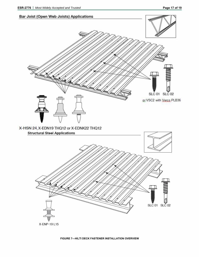
Powder-driven frame fasteners must be installed in the specified pattern, and sidelap connectors must be installed at the specified spacing (see Figure 6a) or number of connectors per span (see Figure 6b). For conversion of specified fastener spacing to the number of sidelap fasteners to be installed, see Table 12. The powder-driven frame fastener patterns are shown in Figure 3. Figure 4 shows typical frame and sidelap connector connections details. Figure 7 provides an overview of the steel deck fastening systems recognized in this report.
5.0 CONDITIONS OF USE Steel deck diaphragms comprised of steel deck panels attached to steel supports with Hilti X-HSN 24,

ESR-2776 | Most Widely Accepted and Trusted Page 4 of 19
X-EDNK22 THQ12, X-EDN19 THQ12 or X-ENP-19 L15 powder-driven fasteners, with Hilti S-SLC 01 M HWH or Hilti S-SLC 02 M HWH sidelap connectors, or Verco’s VSC2 sidelap connection, as described in this report, comply with, or are suitable alternatives to what is specified in, those codes listed in Section 1.0 of this report, subject to the following conditions:
5.1 The fasteners are manufactured, identified and installed in accordance with this report, the manufacturer’s instructions and the approved plans. If there is a conflict, this report governs.
5.2 Steel deck panels must comply with this report.
5.3 Diaphragm shear strength and stiffness must be calculated in accordance with Section 4.1 and Tables 4 through 9 of this report.
5.4 No adjustment for duration of load is permitted.
5.5 Steel deck diaphragms may be zoned by varying steel deck panel gage and/or connections across a diaphragm to meet varying shear and flexibility demands.
5.6 For intermediate steel deck panel thicknesses or panel steel strengths, diaphragm strength and stiffness values shall be based on straight-line interpolation between values determined in accordance with Section 4.1, as described in the note at the end of the diaphragm design example shown in Figure 8.
5.7 The design of the steel deck panels for vertical loads is outside the scope of this report.
5.8 Calculations demonstrating compliance with this report must be submitted to the code official for approval. The calculations must be prepared by a registered design professional where required by the
statutes of the jurisdiction in which the project is to be constructed.
5.9 Hilti fasteners may be used for attachment of steel deck roof systems temporarily exposed to the exterior during construction prior to application of built-up roof covering systems. The fasteners on permanently exposed steel deck roof coverings must be covered with a corrosion-resistant paint or sealant. As an alternate to applying a corrosion-resistant paint or sealant to the Hilti X-ENP-19 L15 fasteners, these fasteners may be used in conjunction with the SDK2 Stainless Steel Sealing Caps, described in Section 3.1 of this report, on permanently exposed steel deck roof coverings. For permanently exposed steel deck roof covering installations, the roof covering system’s compliance with Chapter 15 of the code must be justified to the satisfaction of the code official.
6.0 EVIDENCE SUBMITTED 6.1 Data in accordance with the ICC-ES Acceptance
Criteria for Steel Deck Roof and Floor Systems (AC43), dated October 2010 (editorially revised September, 2013).
6.2 Data in accordance with the ICC-ES Acceptance Criteria for Fasteners Power-driven into Concrete, Steel and Masonry Elements (AC70), dated June 2014.
7.0 IDENTIFICATION
All Hilti powder-driven fasteners and sidelap connectors described in this report are identified by an “H” stamped on the fastener head. All fasteners are packaged in containers noting the product designation, the company name of Hilti, Inc. and the evaluation report number (ESR-2776).
ESR-2776 | Most Widely Accepted and Trusted Page 5 of 19
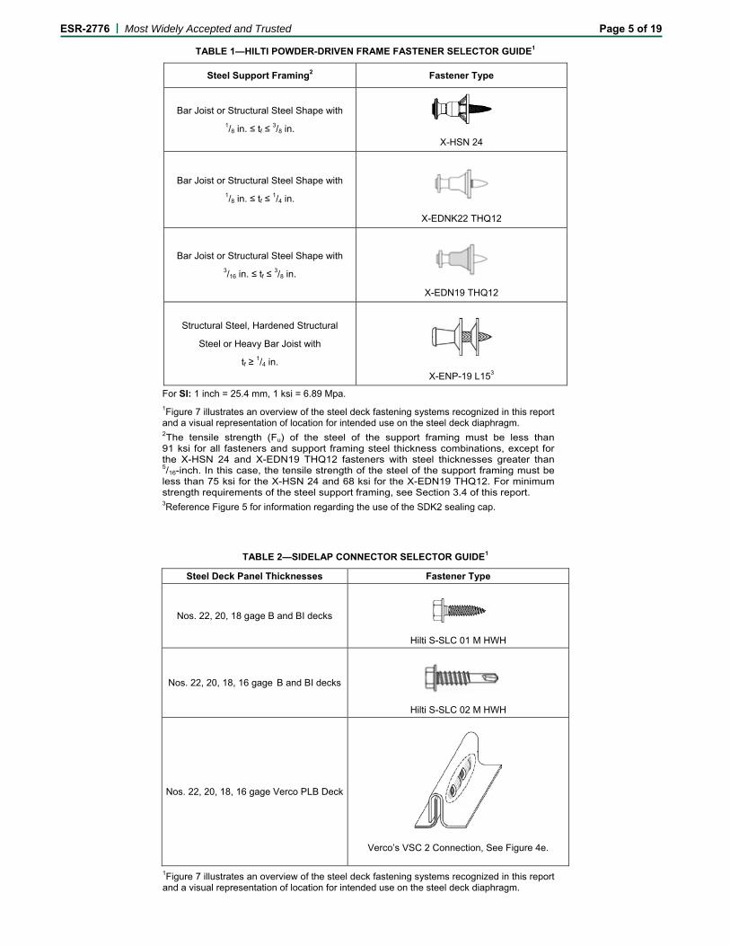
TABLE 1—HILTI POWDER-DRIVEN FRAME FASTENER SELECTOR GUIDE1
Steel Support Framing2 Fastener Type
Bar Joist or Structural Steel Shape with 1/8 in. ≤ tf ≤ 3/8 in.
X-HSN 24
Bar Joist or Structural Steel Shape with 1/8 in. ≤ tf ≤ 1/4 in.
X-EDNK22 THQ12
Bar Joist or Structural Steel Shape with 3/16 in. ≤ tf ≤ 3/8 in.
X-EDN19 THQ12
Structural Steel, Hardened Structural
Steel or Heavy Bar Joist with
tf ≥ 1/4 in.
X-ENP-19 L153
For SI: 1 inch = 25.4 mm, 1 ksi = 6.89 Mpa. 1Figure 7 illustrates an overview of the steel deck fastening systems recognized in this report and a visual representation of location for intended use on the steel deck diaphragm. 2The tensile strength (Fu) of the steel of the support framing must be less than 91 ksi for all fasteners and support framing steel thickness combinations, except for the X-HSN 24 and X-EDN19 THQ12 fasteners with steel thicknesses greater than 5/16-inch. In this case, the tensile strength of the steel of the support framing must be less than 75 ksi for the X-HSN 24 and 68 ksi for the X-EDN19 THQ12. For minimum strength requirements of the steel support framing, see Section 3.4 of this report. 3Reference Figure 5 for information regarding the use of the SDK2 sealing cap.
TABLE 2—SIDELAP CONNECTOR SELECTOR GUIDE1
Steel Deck Panel Thicknesses Fastener Type
Nos. 22, 20, 18 gage B and BI decks
Hilti S-SLC 01 M HWH
Nos. 22, 20, 18, 16 gage B and BI decks
Hilti S-SLC 02 M HWH
Nos. 22, 20, 18, 16 gage Verco PLB Deck
Verco’s VSC 2 Connection, See Figure 4e.
1Figure 7 illustrates an overview of the steel deck fastening systems recognized in this report and a visual representation of location for intended use on the steel deck diaphragm.

ESR-2776 | Most Widely Accepted and Trusted Page 6 of 19
TABLE 3—STEEL DECK PANEL SELECTOR GUIDE1,2,3
1B-Deck (nestable) and BI-Deck (interlocking) deck panel thicknesses must be 16, 18, 20 or 22 gage steel [(54, 43, 33 or 27 mil designations) (0.0598, 0.0474, 0.0358 or 0.0295 inch) (1.51, 1.21, 0.91 or 0.76 mm)], respectively. Intermediate steel deck panel thicknesses may be used (Reference Section 5.6 of this report). 2PLB (interlocking) deck panel thicknesses must be 16, 18, 20 or 22 gage steel [(54, 43, 33 or 27 mil designations) (0.0598, 0.0478, 0.0359 or 0.0299 inch) (1.51, 1.21, 0.91 or 0.76 mm)], respectively. Intermediate steel deck panel thicknesses may be used (Reference Section 5.6 of this report). 3BI-Deck (interlocking) deck panels must have screwable sidelap edges for use with Hilti SLC fasteners.
TABLE 4—DIAPHRAGM STRENGTH (S) AND STIFFNESS FACTOR (G′) EQUATION VARIABLE VALUES (to be used with equations in Sections 4.1.2 and 4.1.3)
Deck Type1 Frame
Fastener Pattern2
α1 – end distribution
factor
α2 – purlin distribution
factor Σxe
2, in.2 Σxp2, in.2 A N
ft.-1
D – Warping Constant, in. No. 22 gage
No. 20 gage
No. 18 gage
No. 16 gage
B- or BI-
Deck
36/11 3.667 3.667 1,944 1,944 2 3.000 1,548 1,164 756 540 36/9 3.000 3.000 1,656 1,656 2 2.333 1,548 1,164 756 540 36/7 2.000 2.000 1,008 1,008 1 2.000 1,548 1,164 756 540 36/5 1.667 1.667 936 936 1 1.333 9,096 6,804 4,464 3,144 36/4 1.333 1.333 720 720 1 1.000 12,864 9,624 6,312 4,452 36/3 1.000 1.000 648 648 1 0.667 26,508 19,824 13,008 9,180
Verco PLB Deck
36/11 3.667 3.667 1,944 1,944 2 3.667 1,548 1,164 756 540 36/9 3.000 3.000 1,656 1,656 2 3.000 1,548 1,164 756 540 36/8 2.333 2.333 1,152 1,152 2 2.667 2,263 2,065 1,790 1,600 36/7 2.000 2.000 1,008 1,008 1 2.333 1,548 1,164 756 540 36/6 1.500 1.500 684 684 1 2.000 1,992 1,818 1,576 1,409
For SI: 1inch = 25.4 mm, 1 in.2 = 645 mm2, 1 ft-1 = 3.28m-1. 1See Table 3 for applicable steel deck panels. 2See Figure 3a and 3b for frame fastener patterns.
Deck Type Nominal Dimensions Deck Type Nominal
Dimensions
B-Deck
BI-Deck and Verco PLB
Deck
ESR-2776 | Most Widely Accepted and Trusted Page 7 of 19
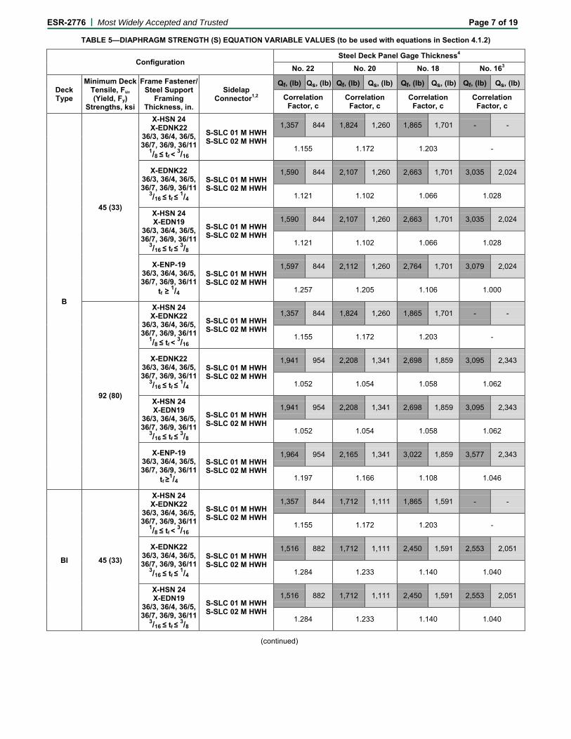
TABLE 5—DIAPHRAGM STRENGTH (S) EQUATION VARIABLE VALUES (to be used with equations in Section 4.1.2)
Configuration Steel Deck Panel Gage Thickness4
No. 22 No. 20 No. 18 No. 163
Deck Type
Minimum Deck Tensile, Fu, (Yield, Fy)
Strengths, ksi
Frame Fastener/ Steel Support
Framing Thickness, in.
Sidelap Connector1,2
Qf, (lb) Qs, (lb) Qf, (lb) Qs, (lb) Qf, (lb) Qs, (lb) Qf, (lb) Qs, (lb)
Correlation Factor, c
Correlation Factor, c
Correlation Factor, c
Correlation Factor, c
B
45 (33)
X-HSN 24 X-EDNK22
36/3, 36/4, 36/5, 36/7, 36/9, 36/11
1/8 ≤ tf < 3/16
S-SLC 01 M HWH S-SLC 02 M HWH
1,357 844 1,824 1,260 1,865 1,701 - -
1.155 1.172 1.203 -
X-EDNK22 36/3, 36/4, 36/5, 36/7, 36/9, 36/11
3/16 ≤ tf ≤ 1/4
S-SLC 01 M HWH S-SLC 02 M HWH
1,590 844 2,107 1,260 2,663 1,701 3,035 2,024
1.121 1.102 1.066 1.028
X-HSN 24 X-EDN19
36/3, 36/4, 36/5, 36/7, 36/9, 36/11
3/16 ≤ tf ≤ 3/8
S-SLC 01 M HWH S-SLC 02 M HWH
1,590 844 2,107 1,260 2,663 1,701 3,035 2,024
1.121 1.102 1.066 1.028
X-ENP-19 36/3, 36/4, 36/5, 36/7, 36/9, 36/11
tf ≥ 1/4
S-SLC 01 M HWH S-SLC 02 M HWH
1,597 844 2,112 1,260 2,764 1,701 3,079 2,024
1.257 1.205 1.106 1.000
92 (80)
X-HSN 24 X-EDNK22
36/3, 36/4, 36/5, 36/7, 36/9, 36/11
1/8 ≤ tf < 3/16
S-SLC 01 M HWH S-SLC 02 M HWH
1,357 844 1,824 1,260 1,865 1,701 - -
1.155 1.172 1.203 -
X-EDNK22 36/3, 36/4, 36/5, 36/7, 36/9, 36/11
3/16 ≤ tf ≤ 1/4
S-SLC 01 M HWH S-SLC 02 M HWH
1,941 954 2,208 1,341 2,698 1,859 3,095 2,343
1.052 1.054 1.058 1.062
X-HSN 24 X-EDN19
36/3, 36/4, 36/5, 36/7, 36/9, 36/11
3/16 ≤ tf ≤ 3/8
S-SLC 01 M HWH S-SLC 02 M HWH
1,941 954 2,208 1,341 2,698 1,859 3,095 2,343
1.052 1.054 1.058 1.062
X-ENP-19 36/3, 36/4, 36/5, 36/7, 36/9, 36/11
tf ≥1/4
S-SLC 01 M HWH S-SLC 02 M HWH
1,964 954 2,165 1,341 3,022 1,859 3,577 2,343
1.197 1.166 1.108 1.046
BI 45 (33)
X-HSN 24 X-EDNK22
36/3, 36/4, 36/5, 36/7, 36/9, 36/11
1/8 ≤ tf < 3/16
S-SLC 01 M HWH S-SLC 02 M HWH
1,357 844 1,712 1,111 1,865 1,591 - -
1.155 1.172 1.203 -
X-EDNK22 36/3, 36/4, 36/5, 36/7, 36/9, 36/11
3/16 ≤ tf ≤ 1/4
S-SLC 01 M HWH S-SLC 02 M HWH
1,516 882 1,712 1,111 2,450 1,591 2,553 2,051
1.284 1.233 1.140 1.040
X-HSN 24 X-EDN19
36/3, 36/4, 36/5, 36/7, 36/9, 36/11
3/16 ≤ tf ≤ 3/8
S-SLC 01 M HWH S-SLC 02 M HWH
1,516 882 1,712 1,111 2,450 1,591 2,553 2,051
1.284 1.233 1.140 1.040
(continued)
ESR-2776 | Most Widely Accepted and Trusted Page 8 of 19
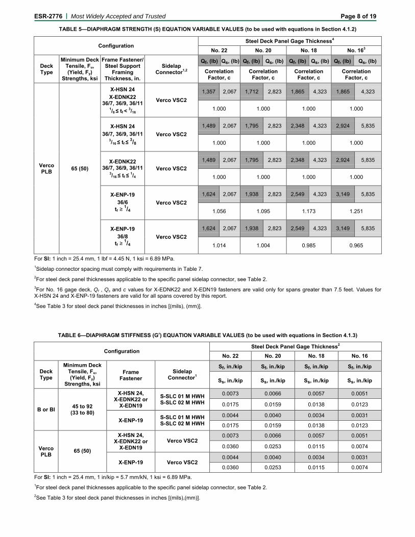
TABLE 5—DIAPHRAGM STRENGTH (S) EQUATION VARIABLE VALUES (to be used with equations in Section 4.1.2)
Configuration Steel Deck Panel Gage Thickness4
No. 22 No. 20 No. 18 No. 163
Deck Type
Minimum Deck Tensile, Fu, (Yield, Fy)
Strengths, ksi
Frame Fastener/ Steel Support
Framing Thickness, in.
Sidelap Connector1,2
Qf, (lb) Qs, (lb) Qf, (lb) Qs, (lb) Qf, (lb) Qs, (lb) Qf, (lb) Qs, (lb)
Correlation Factor, c
Correlation Factor, c
Correlation Factor, c
Correlation Factor, c
Verco PLB 65 (50)
X-HSN 24 X-EDNK22
36/7, 36/9, 36/11 1/8 ≤ tf < 3/16
Verco VSC2 1,357 2,067 1,712 2,823 1,865 4,323 1,865 4,323
1.000 1.000 1.000 1.000
X-HSN 24 36/7, 36/9, 36/11
3/16 ≤ tf ≤ 3/8 Verco VSC2
1,489 2,067 1,795 2,823 2,348 4,323 2,924 5,835
1.000 1.000 1.000 1.000
X-EDNK22 36/7, 36/9, 36/11
3/16 ≤ tf ≤ 1/4 Verco VSC2
1,489 2,067 1,795 2,823 2,348 4,323 2,924 5,835
1.000 1.000 1.000 1.000
X-ENP-19 36/6
tf ≥ 1/4 Verco VSC2
1,624 2,067 1,938 2,823 2,549 4,323 3,149 5,835
1.056 1.095 1.173 1.251
X-ENP-19 36/8
tf ≥ 1/4 Verco VSC2
1,624 2,067 1,938 2,823 2,549 4,323 3,149 5,835
1.014 1.004 0.985 0.965
For SI: 1 inch = 25.4 mm, 1 lbf = 4.45 N, 1 ksi = 6.89 MPa. 1Sidelap connector spacing must comply with requirements in Table 7. 2For steel deck panel thicknesses applicable to the specific panel sidelap connector, see Table 2. 3For No. 16 gage deck, Qf , Qs and c values for X-EDNK22 and X-EDN19 fasteners are valid only for spans greater than 7.5 feet. Values for X-HSN 24 and X-ENP-19 fasteners are valid for all spans covered by this report. 4See Table 3 for steel deck panel thicknesses in inches [(mils), (mm)].
TABLE 6—DIAPHRAGM STIFFNESS (G′) EQUATION VARIABLE VALUES (to be used with equations in Section 4.1.3)
Configuration Steel Deck Panel Gage Thickness2
No. 22 No. 20 No. 18 No. 16
Deck Type
Minimum Deck Tensile, Fu, (Yield, Fy)
Strengths, ksi
Frame Fastener
Sidelap Connector1
Sf, in./kip Sf, in./kip Sf, in./kip Sf, in./kip
Ss, in./kip Ss, in./kip Ss, in./kip Ss, in./kip
B or BI 45 to 92 (33 to 80)
X-HSN 24, X-EDNK22 or
X-EDN19 S-SLC 01 M HWH S-SLC 02 M HWH
0.0073 0.0066 0.0057 0.0051
0.0175 0.0159 0.0138 0.0123
X-ENP-19 S-SLC 01 M HWH S-SLC 02 M HWH
0.0044 0.0040 0.0034 0.0031
0.0175 0.0159 0.0138 0.0123
Verco PLB
65 (50)
X-HSN 24, X-EDNK22 or
X-EDN19 Verco VSC2
0.0073 0.0066 0.0057 0.0051
0.0360 0.0253 0.0115 0.0074
X-ENP-19 Verco VSC2 0.0044 0.0040 0.0034 0.0031
0.0360 0.0253 0.0115 0.0074
For SI: 1 inch = 25.4 mm, 1 in/kip = 5.7 mm/kN, 1 ksi = 6.89 MPa. 1For steel deck panel thicknesses applicable to the specific panel sidelap connector, see Table 2. 2See Table 3 for steel deck panel thicknesses in inches [(mils),(mm)].
ESR-2776 | Most Widely Accepted and Trusted Page 9 of 19
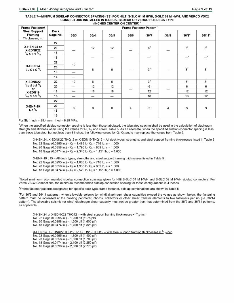
TABLE 7—MINIMUM SIDELAP CONNECTOR SPACING (SS) FOR HILTI S-SLC 01 M HWH, S-SLC 02 M HWH, AND VERCO VSC2 CONNECTORS INSTALLED IN B-DECK, BI-DECK OR VERCO PLB DECK TYPE
(INCHES CENTER ON CENTER) 1 Frame Fastener/
Steel Support Framing
Thickness, in.
Deck Gage No.
Frame Fastener Pattern3
36/3 36/4 36/5 36/6 36/7 36/8 36/94 36/114
X-HSN 24 or X-EDNK22 1/8 ≤ tf < 3/16
22
— 12 12
— 62
— 62 62 20
18 16 — — —2 —2 —2
X-HSN 24 3/16 ≤ tf ≤ 3/8
22 12
6 6 — 32 — 32 32 20 18 — 16 —
X-EDNK22 3/16 ≤ tf ≤ 1/4
or X-EDN19
3/16 ≤ tf ≤ 3/8
22 12 6 6
—
32
—
32 32 20 — 12 12 6 6 6 18 — 18 18 12 12 12 16 — — — 18 18 12
X-ENP-19 tf ≥ 1/4
22
6 6 6 4 3 4 3 3 20 18 16
For SI: 1 inch = 25.4 mm, 1 ksi = 6.89 MPa. 1When the specified sidelap connector spacing is less than those tabulated, the tabulated spacing shall be used in the calculation of diaphragm strength and stiffness when using the values for Qf, Qs and c from Table 5. As an alternate, when the specified sidelap connector spacing is less than those tabulated, but not less than 3 inches, the following values for Qf, Qs and c may replace the values from Table 5:
X-HSN 24, X-EDNK22 THQ12 or X-EDN19 THQ12 – All deck types, strengths, and steel support framing thicknesses listed in Table 5 No. 22 Gage (0.0295 in.) – Qf = 1,489 lb, Qs = 716 lb, c = 1.000 No. 20 Gage (0.0358 in.) – Qf = 1,795 lb, Qs = 869 lb, c = 1.000 No. 18 Gage (0.0474 in.) – Qf = 2,348 lb, Qs = 1,151 lb, c = 1.000 X-ENP-19 L15 – All deck types, strengths and steel support framing thicknesses listed in Table 5 No. 22 Gage (0.0295 in.) – Qf = 1,603 lb, Qs = 716 lb, c = 1.000 No. 20 Gage (0.0358 in.) – Qf = 1,933 lb, Qs = 869 lb, c = 1.000 No. 18 Gage (0.0474 in.) – Qf = 2,529 lb, Qs = 1,151 lb, c = 1.000
2Noted minimum recommended sidelap connection spacings given for Hilti S-SLC 01 M HWH and S-SLC 02 M HWH sidelap connectors. For Verco VSC2 Connections, the minimum recommended sidelap connection spacing for these configurations is 4 inches. 3Frame fastener patterns recognized for specific deck type, frame fastener, sidelap combinations are shown in Table 5. 4For 36/9 and 36/11 patterns , when allowable seismic (or wind) diaphragm shear capacities exceed the values as shown below, the fastening pattern must be increased at the building perimeter, chords, collectors or other shear transfer elements to two fasteners per rib (i.e. 36/14 pattern). The allowable seismic (or wind) diaphragm shear capacity must not be greater than that determined from the 36/9 and 36/11 patterns, as applicable.
X-HSN 24 or X-EDNK22 THQ12 – with steel support framing thicknesses < 3/16-inch No. 22 Gage (0.0295 in.) – 1,200 plf (1275 plf) No. 20 Gage (0.0358 in.) – 1,500 plf (1,600 plf) No. 18 Gage (0.0474 in.) – 1,700 plf (1,825 plf) X-HSN 24, X-EDNK22 THQ12, or X-EDN19 THQ12 – with steel support framing thicknesses ≥ 3/16-inch No. 22 Gage (0.0295 in.) – 1,300 plf (1,400 plf) No. 20 Gage (0.0358 in.) – 1,600 plf (1,700 plf) No. 18 Gage (0.0474 in.) – 2,100 plf (2,250 plf) No. 16 Gage (0.0598 in.) – 2,600 plf (2,775 plf)
ESR-2776 | Most Widely Accepted and Trusted Page 10 of 19
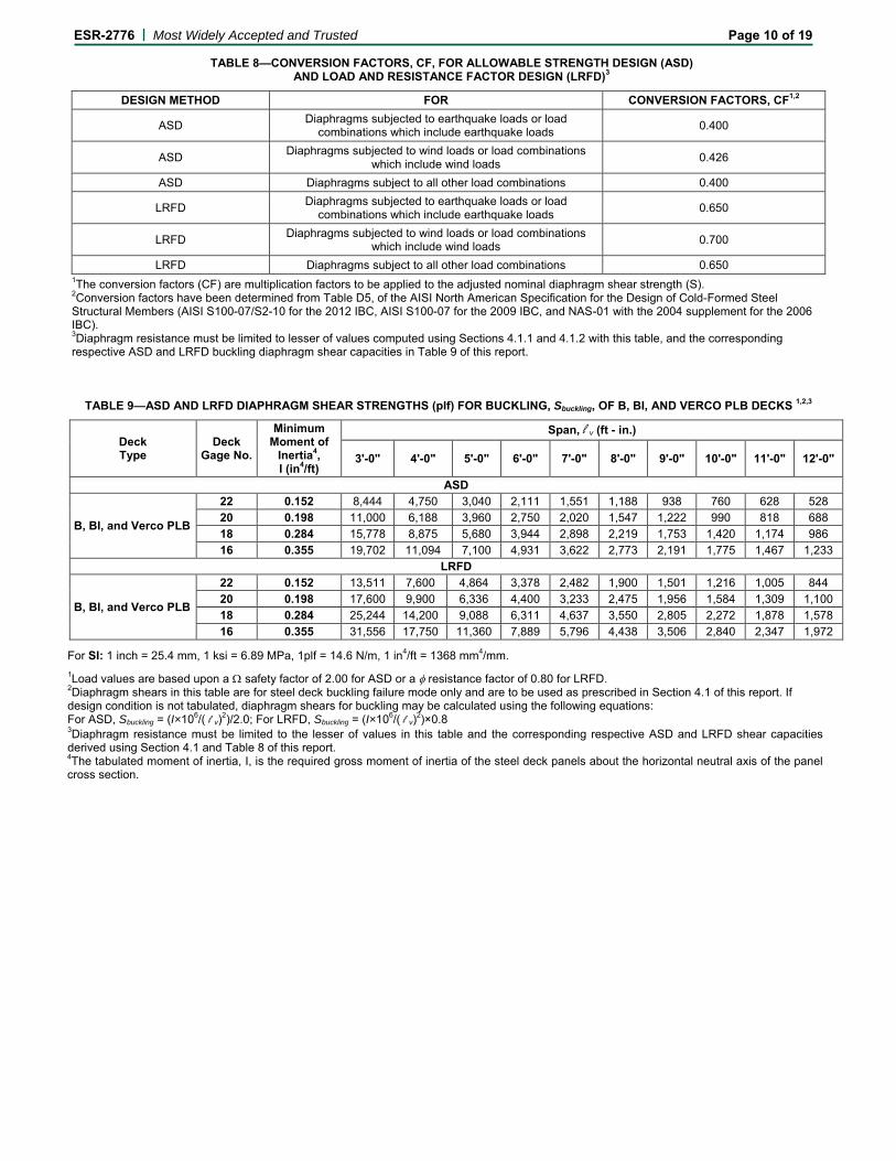
TABLE 8—CONVERSION FACTORS, CF, FOR ALLOWABLE STRENGTH DESIGN (ASD) AND LOAD AND RESISTANCE FACTOR DESIGN (LRFD)3
DESIGN METHOD FOR CONVERSION FACTORS, CF1,2
ASD Diaphragms subjected to earthquake loads or load combinations which include earthquake loads 0.400
ASD Diaphragms subjected to wind loads or load combinations which include wind loads 0.426
ASD Diaphragms subject to all other load combinations 0.400
LRFD Diaphragms subjected to earthquake loads or load combinations which include earthquake loads 0.650
LRFD Diaphragms subjected to wind loads or load combinations which include wind loads 0.700
LRFD Diaphragms subject to all other load combinations 0.650 1The conversion factors (CF) are multiplication factors to be applied to the adjusted nominal diaphragm shear strength (S). 2Conversion factors have been determined from Table D5, of the AISI North American Specification for the Design of Cold-Formed Steel Structural Members (AISI S100-07/S2-10 for the 2012 IBC, AISI S100-07 for the 2009 IBC, and NAS-01 with the 2004 supplement for the 2006 IBC). 3Diaphragm resistance must be limited to lesser of values computed using Sections 4.1.1 and 4.1.2 with this table, and the corresponding respective ASD and LRFD buckling diaphragm shear capacities in Table 9 of this report.
TABLE 9—ASD AND LRFD DIAPHRAGM SHEAR STRENGTHS (plf) FOR BUCKLING, Sbuckling, OF B, BI, AND VERCO PLB DECKS 1,2,3
Deck Type
Deck Gage No.
Minimum Moment of
Inertia4, I (in4/ft)
Span, l v (ft - in.)
3'-0" 4'-0" 5'-0" 6'-0" 7'-0" 8'-0" 9'-0" 10'-0" 11'-0" 12'-0"
ASD
B, BI, and Verco PLB
22 0.152 8,444 4,750 3,040 2,111 1,551 1,188 938 760 628 528 20 0.198 11,000 6,188 3,960 2,750 2,020 1,547 1,222 990 818 688 18 0.284 15,778 8,875 5,680 3,944 2,898 2,219 1,753 1,420 1,174 986 16 0.355 19,702 11,094 7,100 4,931 3,622 2,773 2,191 1,775 1,467 1,233
LRFD
B, BI, and Verco PLB
22 0.152 13,511 7,600 4,864 3,378 2,482 1,900 1,501 1,216 1,005 844 20 0.198 17,600 9,900 6,336 4,400 3,233 2,475 1,956 1,584 1,309 1,100 18 0.284 25,244 14,200 9,088 6,311 4,637 3,550 2,805 2,272 1,878 1,578 16 0.355 31,556 17,750 11,360 7,889 5,796 4,438 3,506 2,840 2,347 1,972
For SI: 1 inch = 25.4 mm, 1 ksi = 6.89 MPa, 1plf = 14.6 N/m, 1 in4/ft = 1368 mm4/mm. 1Load values are based upon a Ω safety factor of 2.00 for ASD or a φ resistance factor of 0.80 for LRFD. 2Diaphragm shears in this table are for steel deck buckling failure mode only and are to be used as prescribed in Section 4.1 of this report. If design condition is not tabulated, diaphragm shears for buckling may be calculated using the following equations: For ASD, Sbuckling = (I×106/( l v)2)/2.0; For LRFD, Sbuckling = (I×106/( l v)2)×0.8 3Diaphragm resistance must be limited to the lesser of values in this table and the corresponding respective ASD and LRFD shear capacities derived using Section 4.1 and Table 8 of this report. 4The tabulated moment of inertia, I, is the required gross moment of inertia of the steel deck panels about the horizontal neutral axis of the panel cross section.
ESR-2776 | Most Widely Accepted and Trusted Page 11 of 19
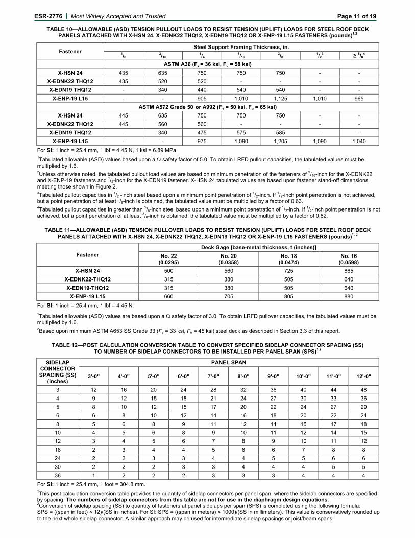
TABLE 10—ALLOWABLE (ASD) TENSION PULLOUT LOADS TO RESIST TENSION (UPLIFT) LOADS FOR STEEL ROOF DECK PANELS ATTACHED WITH X-HSN 24, X-EDNK22 THQ12, X-EDN19 THQ12 OR X-ENP-19 L15 FASTENERS (pounds)1,2
Fastener Steel Support Framing Thickness, in.
1/8 3/16 1/4 5/16 3/8 1/23 ≥ 5/84
ASTM A36 (Fy = 36 ksi, Fu = 58 ksi) X-HSN 24 435 635 750 750 750 - -
X-EDNK22 THQ12 435 520 520 - - - - X-EDN19 THQ12 - 340 440 540 540 - -
X-ENP-19 L15 - - 905 1,010 1,125 1,010 965 ASTM A572 Grade 50 or A992 (Fy = 50 ksi, Fu = 65 ksi)
X-HSN 24 445 635 750 750 750 - - X-EDNK22 THQ12 445 560 560 - - - - X-EDN19 THQ12 - 340 475 575 585 - -
X-ENP-19 L15 - - 975 1,090 1,205 1,090 1,040 For SI: 1 inch = 25.4 mm, 1 lbf = 4.45 N, 1 ksi = 6.89 MPa. 1Tabulated allowable (ASD) values based upon a Ω safety factor of 5.0. To obtain LRFD pullout capacities, the tabulated values must be multiplied by 1.6. 2Unless otherwise noted, the tabulated pullout load values are based on minimum penetration of the fasteners of 9/16-inch for the X-EDNK22 and X-ENP-19 fasteners and 1/2-inch for the X-EDN19 fastener. X-HSN 24 tabulated values are based upon fastener stand-off dimensions meeting those shown in Figure 2. 3Tabulated pullout capacities in 1/2 -inch steel based upon a minimum point penetration of 1/2-inch. If 1/2-inch point penetration is not achieved, but a point penetration of at least 3/8-inch is obtained, the tabulated value must be multiplied by a factor of 0.63. 4Tabulated pullout capacities in greater than 5/8-inch steel based upon a minimum point penetration of 1/2-inch. If 1/2-inch point penetration is not achieved, but a point penetration of at least 3/8-inch is obtained, the tabulated value must be multiplied by a factor of 0.82.
TABLE 11—ALLOWABLE (ASD) TENSION PULLOVER LOADS TO RESIST TENSION (UPLIFT) LOADS FOR STEEL ROOF DECK PANELS ATTACHED WITH X-HSN 24, X-EDNK22 THQ12, X-EDN19 THQ12 OR X-ENP-19 L15 FASTENERS (pounds)1, 2
Fastener Deck Gage [base-metal thickness, t (inches)]
No. 22 (0.0295)
No. 20 (0.0358)
No. 18 (0.0474)
No. 16 (0.0598)
X-HSN 24 500 560 725 865 X-EDNK22-THQ12 315 380 505 640 X-EDN19-THQ12 315 380 505 640
X-ENP-19 L15 660 705 805 880 For SI: 1 inch = 25.4 mm, 1 lbf = 4.45 N. 1Tabulated allowable (ASD) values are based upon a Ω safety factor of 3.0. To obtain LRFD pullover capacities, the tabulated values must be multiplied by 1.6. 2Based upon minimum ASTM A653 SS Grade 33 (Fy = 33 ksi, Fu = 45 ksi) steel deck as described in Section 3.3 of this report.
TABLE 12—POST CALCULATION CONVERSION TABLE TO CONVERT SPECIFIED SIDELAP CONNECTOR SPACING (SS)
TO NUMBER OF SIDELAP CONNECTORS TO BE INSTALLED PER PANEL SPAN (SPS)1,2
SIDELAP CONNECTOR SPACING (SS)
(inches)
PANEL SPAN
3'-0" 4'-0" 5'-0" 6'-0" 7'-0" 8'-0" 9'-0" 10'-0" 11'-0" 12'-0"
3 12 16 20 24 28 32 36 40 44 48 4 9 12 15 18 21 24 27 30 33 36 5 8 10 12 15 17 20 22 24 27 29 6 6 8 10 12 14 16 18 20 22 24 8 5 6 8 9 11 12 14 15 17 18
10 4 5 6 8 9 10 11 12 14 15 12 3 4 5 6 7 8 9 10 11 12 18 2 3 4 4 5 6 6 7 8 8 24 2 2 3 3 4 4 5 5 6 6 30 2 2 2 3 3 4 4 4 5 5 36 1 2 2 2 3 3 3 4 4 4
For SI: 1 inch = 25.4 mm, 1 foot = 304.8 mm. 1This post calculation conversion table provides the quantity of sidelap connectors per panel span, where the sidelap connectors are specified by spacing. The numbers of sidelap connectors from this table are not for use in the diaphragm design equations. 2Conversion of sidelap spacing (SS) to quantity of fasteners at panel sidelaps per span (SPS) is completed using the following formula: SPS = ((span in feet) × 12)/(SS in inches). For SI: SPS = ((span in meters) × 1000)/(SS in millimeters). This value is conservatively rounded up to the next whole sidelap connector. A similar approach may be used for intermediate sidelap spacings or joist/beam spans.
ESR-2776 | Most Widely Accepted and Trusted Page 12 of 19 FOOTNOTES TO TABLES 4 THROUGH 12
1. Hilti X-HSN 24, X-EDNK22 THQ12, X-EDN19 THQ12 or X-ENP-19 L15 frame fasteners must be used at all panel ends, interior supports and panel edges parallel to the panel corrugations. The sides of adjacent panels parallel to the corrugations must be lapped by nesting or interlocking and then fastened with Hilti S-SLC 01 M HWH, Hilti S-SLC 02 M HWH sidelap connectors, or Verco VSC2 sidelap connections along the panel-to-panel side seam overlap.
2. The following apply to diaphragms designed in accordance with this report:
a. The deck sheet length is equal to the span times the number of spans.
b. For steel deck diaphragms, the number of diaphragm edge fasteners at walls or transfer zones parallel to the deck corrugations must be greater than or equal to the number of stitch sidelap connectors at nearest interior sidelaps.
3. All equations and tables apply to wide rib 11/2-inch-deep (38 mm) steel deck panels complying with Section 3.3 of this report.
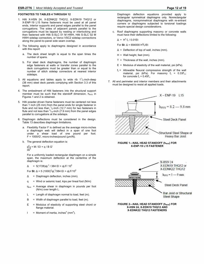
4. The embedment of Hilti fasteners into the structural support member must be such that the standoff dimension, hNVS in Figures 1 and 2 is obtained.
5. Hilti powder-driven frame fasteners must be centered not less than 1 inch (25 mm) from the panel ends for single fastener in flute and not less than 1/2-inch (12.7 mm) for two fasteners in flute and not less than 5/16-inch (7.9 mm) from the panel edges parallel to corrugations at the sidelaps.
6. Diaphragm deflections must be considered in the design. Table 13 describes diaphragm limitations.
a. Flexibility Factor F is defined as the average micro-inches a diaphragm web will deflect in a span of one foot under a shear load of one pound per foot. F = 1000/G', micro-inches/pound (μm/N).
b. The general deflection equation is:
d2y = M / EI + q / B G' dx2
For a uniformly loaded rectangular diaphragm on a simple span, the maximum deflection at the centerline of the diaphragm is:
Δ = 5(1728)qL4 / 384 EI + qLF/ 106
For SI: Δ = 5 (1000)4qL4/384 EI + qLF/106
Δ = Diaphragm deflection, inches (mm).
q = Wind or seismic load, kips per lineal foot (N/m)
qave = Average shear in diaphragm in pounds per foot (N/m) over length L.
L = Length of diaphragm normal to load, feet (m).
B = Width of diaphragm parallel to load, feet (m).
E = Modulus of elasticity of supporting steel chord or flange material.
I = Moment of inertia, inches4 (mm4).
Diaphragm deflection equations provided apply to rectangular symmetrical diaphragms only. Nonrectangular diaphragms, nonsymmetrical diaphragms with re-entrant corners or diaphragms subjected to torsional loadings require special design considerations.
c. Roof diaphragms supporting masonry or concrete walls must have their deflections limited to the following:
Δ = H2 fc / 0.01Et
For SI: Δ = 694000 H2fc/Et
Δ = Deflection of top of wall, inches (mm).
H = Wall height, feet (mm).
T = Thickness of the wall, inches (mm).
E = Modulus of elasticity of the wall material, psi (kPa).
fc = Allowable flexural compressive strength of the wall material, psi (kPa). For masonry fc = 0.33f'm; for concrete fc = 0.45f'c.
7. All end perimeter and interior members and their attachments must be designed to resist all applied loads.
FIGURE 1—NAIL HEAD STANDOFF (hNVS) FOR X-ENP-19 L15 FASTENER
FIGURE 2—NAIL HEAD STANDOFF (hNVS) FOR X-HSN 24, X-EDN19 THQ12 AND X-EDNK22 THQ12 FASTENERS
ESR-2776 | Most Widely Accepted and Trusted Page 13 of 19
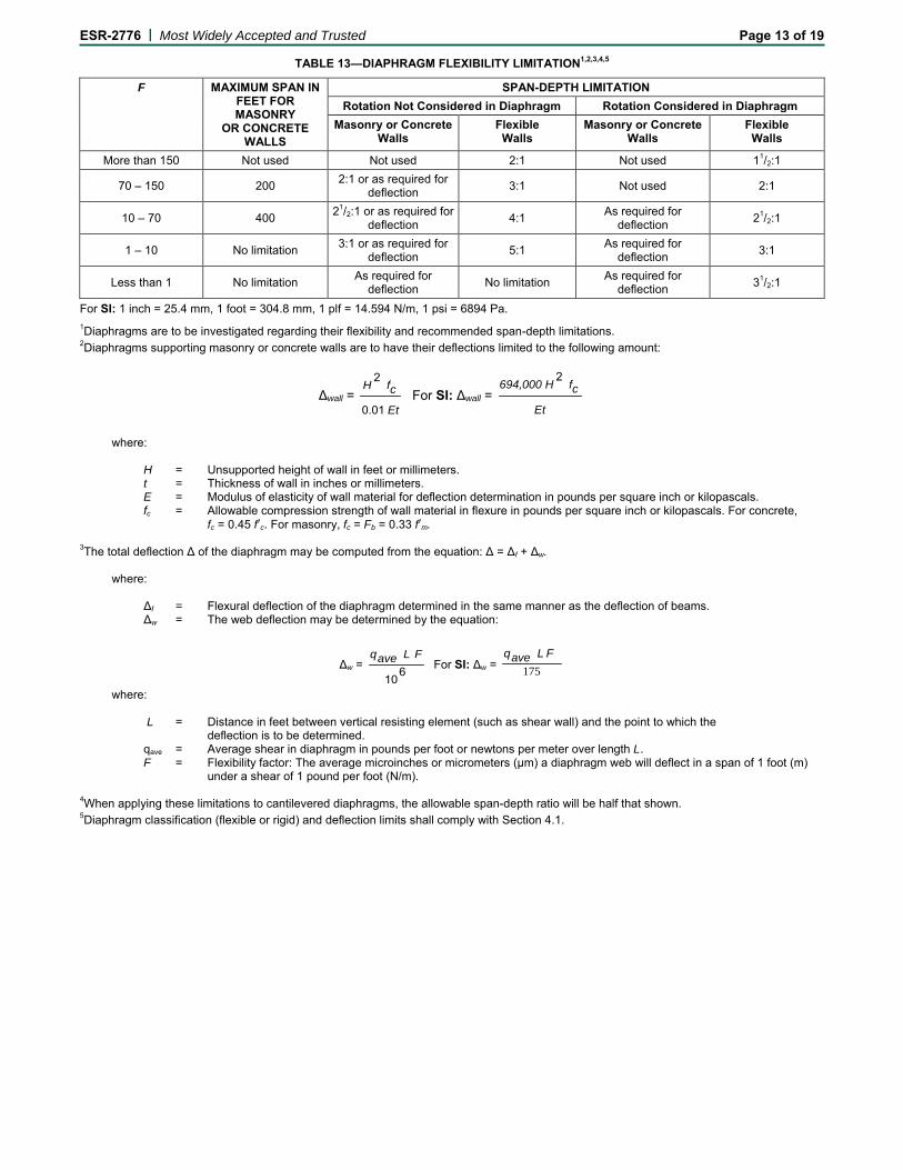
TABLE 13—DIAPHRAGM FLEXIBILITY LIMITATION1,2,3,4,5
F MAXIMUM SPAN IN FEET FOR MASONRY
OR CONCRETE WALLS
SPAN-DEPTH LIMITATION Rotation Not Considered in Diaphragm Rotation Considered in Diaphragm
Masonry or Concrete Walls
Flexible Walls
Masonry or Concrete Walls
Flexible Walls
More than 150 Not used Not used 2:1 Not used 11/2:1
70 – 150 200 2:1 or as required for deflection 3:1 Not used 2:1
10 – 70 400 21/2:1 or as required for deflection 4:1 As required for
deflection 21/2:1
1 – 10 No limitation 3:1 or as required for deflection 5:1 As required for
deflection 3:1
Less than 1 No limitation As required for deflection No limitation As required for
deflection 31/2:1
For SI: 1 inch = 25.4 mm, 1 foot = 304.8 mm, 1 plf = 14.594 N/m, 1 psi = 6894 Pa. 1Diaphragms are to be investigated regarding their flexibility and recommended span-depth limitations. 2Diaphragms supporting masonry or concrete walls are to have their deflections limited to the following amount:
Δwall = Et
cfH
0.01
2 For SI: Δwall =
Et
cfH694,000 2
where: H = Unsupported height of wall in feet or millimeters. t = Thickness of wall in inches or millimeters. E = Modulus of elasticity of wall material for deflection determination in pounds per square inch or kilopascals. fc = Allowable compression strength of wall material in flexure in pounds per square inch or kilopascals. For concrete, fc = 0.45 f′c. For masonry, fc = Fb = 0.33 f′m. 3The total deflection Δ of the diaphragm may be computed from the equation: Δ = Δf + Δw. where: Δf = Flexural deflection of the diaphragm determined in the same manner as the deflection of beams. Δw = The web deflection may be determined by the equation:
Δw = 610
FLaveq For SI: Δw = 175
F Laveq
where: L = Distance in feet between vertical resisting element (such as shear wall) and the point to which the
deflection is to be determined. qave = Average shear in diaphragm in pounds per foot or newtons per meter over length L. F = Flexibility factor: The average microinches or micrometers (μm) a diaphragm web will deflect in a span of 1 foot (m) under a shear of 1 pound per foot (N/m). 4When applying these limitations to cantilevered diaphragms, the allowable span-depth ratio will be half that shown. 5Diaphragm classification (flexible or rigid) and deflection limits shall comply with Section 4.1.
ESR-2776 | Most Widely Accepted and Trusted Page 14 of 19
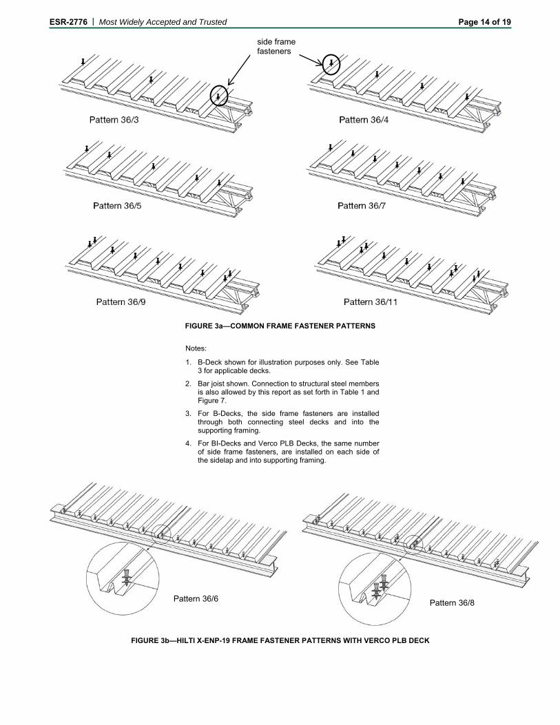
FIGURE 3a—COMMON FRAME FASTENER PATTERNS
Notes:
1. B-Deck shown for illustration purposes only. See Table 3 for applicable decks.
2. Bar joist shown. Connection to structural steel members is also allowed by this report as set forth in Table 1 and Figure 7.
3. For B-Decks, the side frame fasteners are installed through both connecting steel decks and into the supporting framing.
4. For BI-Decks and Verco PLB Decks, the same number of side frame fasteners, are installed on each side of the sidelap and into supporting framing.
FIGURE 3b—HILTI X-ENP-19 FRAME FASTENER PATTERNS WITH VERCO PLB DECK
side frame fasteners
Pattern 36/6 Pattern 36/8

ESR-2776 | Most Widely Accepted and Trusted Page 15 of 19
4e. Verco VSC 2 Connection
FIGURE 4—TYPICAL FRAME, ENDLAP AND SIDELAP CONNECTIONS
Note: To be used with X-ENP-19 L15 fasteners. X-ENP-19 Nailhead standoff (hNVS) must be as shown in Figure 1
FIGURE 5—SDK2 SEALING CAP
Note: Some fastener patterns may require two fasteners. Fasteners may be installed on either side of the structural steel beam or bar joist.
4d. Sidelap Connector with BI-Deck 4c. Sidelap Connector with B-Deck
4b. Steel Deck Endlap Condition
4a. Powder-Driven Fastener Attachment of Steel Deck to Frame
ESR-2776 | Most Widely Accepted and Trusted Page 16 of 19
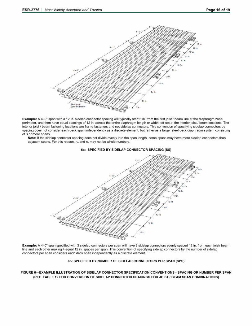
Example: A 4'-0" span with a 12 in. sidelap connector spacing will typically start 6 in. from the first joist / beam line at the diaphragm zone perimeter, and then have equal spacings of 12 in. across the entire diaphragm length or width, off-set at the interior joist / beam locations. The interior joist / beam fastening locations are frame fasteners and not sidelap connectors. This convention of specifying sidelap connectors by spacing does not consider each deck span independently as a discrete element, but rather as a larger steel deck diaphragm system consisting of 3 or more spans.
Note: If the sidelap connector spacing does not divide evenly into the span length, some spans may have more sidelap connectors than adjacent spans. For this reason, ne and ns may not be whole numbers.
6a: SPECIFIED BY SIDELAP CONNECTOR SPACING (SS)
Example: A 4'-0" span specified with 3 sidelap connectors per span will have 3 sidelap connectors evenly spaced 12 in. from each joist/ beam line and each other making 4 equal 12 in. spaces per span. This convention of specifying sidelap connectors by the number of sidelap connectors per span considers each deck span independently as a discrete element.
6b: SPECIFIED BY NUMBER OF SIDELAP CONNECTORS PER SPAN (SPS)
FIGURE 6—EXAMPLE ILLUSTRATION OF SIDELAP CONNECTOR SPECIFICATION CONVENTIONS - SPACING OR NUMBER PER SPAN (REF. TABLE 12 FOR CONVERSION OF SIDELAP CONNECTOR SPACINGS FOR JOIST / BEAM SPAN COMBINATIONS)
ESR-2776 | Most Widely Accepted and Trusted Page 17 of 19
FIGURE 7—HILTI DECK FASTENER INSTALLATION OVERVIEW
ESR-2776 | Most Widely Accepted and Trusted Page 18 of 19
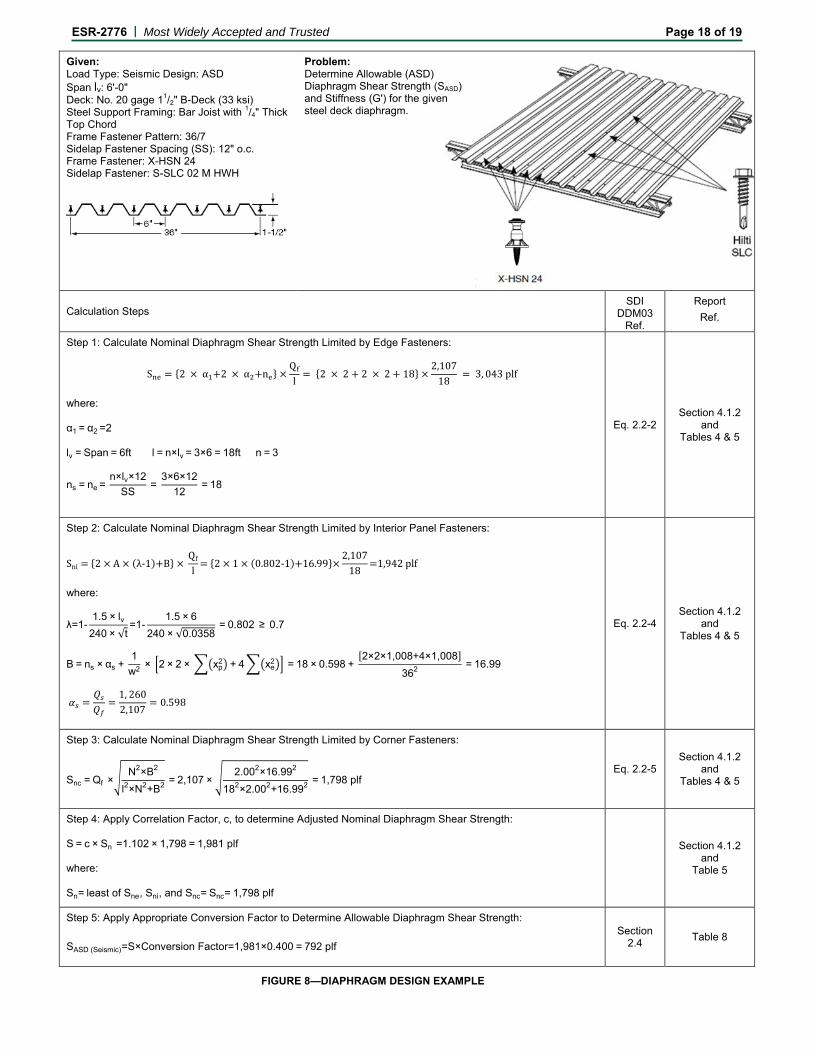
Given: Load Type: Seismic Design: ASD Span lv: 6'-0" Deck: No. 20 gage 11/2" B-Deck (33 ksi) Steel Support Framing: Bar Joist with 1/4" Thick Top Chord Frame Fastener Pattern: 36/7 Sidelap Fastener Spacing (SS): 12" o.c. Frame Fastener: X-HSN 24 Sidelap Fastener: S-SLC 02 M HWH
Problem: Determine Allowable (ASD) Diaphragm Shear Strength (SASD) and Stiffness (G') for the given steel deck diaphragm.
Calculation Steps SDI
DDM03 Ref.
Report Ref.
Sne = 2 × α1+2 × α2+ne ×Qf
l= 2 × 2 + 2 × 2 + 18 ×
2,10718
= 3, 043 plf
α1 = α2 =2
ns = ne = n×lv×12
SS =
3×6×1212
= 18
Step 1: Calculate Nominal Diaphragm Shear Strength Limited by Edge Fasteners:
where:
lv = Span = 6ft l = n×lv = 3×6 = 18ft n = 3
Eq. 2.2-2 Section 4.1.2
and Tables 4 & 5
Sni = 2 × A × (λ-1)+B × Qf
l= 2 × 1 × (0.802-1)+16.99×
2,10718
=1,942 plf
λ=1-1.5 × lv
240 × √t=1-
1.5 × 6240 × √0.0358
= 0.802 ≥ 0.7
B = ns × αs + 1
w2 × 2 × 2 × xp2 + 4xe
2 = 18 × 0.598 + [2×2×1,008+4×1,008]
362 = 16.99
𝛼𝑠 =𝑄𝑠𝑄𝑓
=1, 2602,107
= 0.598
Step 2: Calculate Nominal Diaphragm Shear Strength Limited by Interior Panel Fasteners:
where:
Eq. 2.2-4 Section 4.1.2
and Tables 4 & 5
Snc = Qf ×N2×B2
l2×N2+B2 = 2,107 × 2.002×16.992
182×2.002+16.992 = 1,798 plf
Step 3: Calculate Nominal Diaphragm Shear Strength Limited by Corner Fasteners:
Eq. 2.2-5 Section 4.1.2
and Tables 4 & 5
Sn= least of Sne, Sni, and Snc= Snc= 1,798 plf
Step 4: Apply Correlation Factor, c, to determine Adjusted Nominal Diaphragm Shear Strength: S = c × Sn =1.102 × 1,798 = 1,981 plf where:
Section 4.1.2
and Table 5
SASD (Seismic)=S×Conversion Factor=1,981×0.400 = 792 plf
Step 5: Apply Appropriate Conversion Factor to Determine Allowable Diaphragm Shear Strength:
Section 2.4 Table 8
FIGURE 8—DIAPHRAGM DESIGN EXAMPLE

ESR-2776 | Most Widely Accepted and Trusted Page 19 of 19
NOTE: Straight-line interpolation between different steel deck thicknesses and steel deck strengths for the calculation of diaphragm shear strength values is permitted. For example, to calculate the allowable diaphragm shear strength, SASD, for 65 ksi steel deck, the following formula would be used.
𝑆𝐴𝑆𝐷 (65 𝑘𝑠𝑖) = 𝑆𝐴𝑆𝐷 (45 𝑘𝑠𝑖) + (65 𝑘𝑠𝑖 – 45 𝑘𝑠𝑖) × 𝑆𝐴𝑆𝐷 (92 𝑘𝑠𝑖) − 𝑆𝐴𝑆𝐷 (45 𝑘𝑠𝑖)
92 − 45
where: SASD(45ksi) = Allowable diaphragm shear for 45 ksi steel deck as calculated per Section 4.1.2 of this report. SASD(92ksi) = Allowable diaphragm shear for 92 ksi steel deck as calculated per Section 4.1.2 of this report. SASD(65ksi) = Allowable diaphragm shear for 65 ksi steel deck. Similarly, to calculate the allowable diaphragm shear, SASD, for 19 gauge (0.0418 in.) steel deck, the following formula would be used.
𝑆𝐴𝑆𝐷 (19 𝐺𝑎.) = 𝑆𝐴𝑆𝐷 (20 𝐺𝑎.) + (0.0418 𝑖𝑛.− 0.0358 𝑖𝑛. ) × 𝑆𝐴𝑆𝐷 (18 𝐺𝑎.) − 𝑆𝐴𝑆𝐷 (20 𝐺𝑎.)
0.0474 𝑖𝑛.−0.0358 𝑖𝑛. where: SASD(20Ga.) = Allowable diaphragm shear for 20 gauge (0.0358 in.) steel deck as calculated per Section 4.1.2 of this report. SASD(18Ga.) = Allowable diaphragm shear for 18 gauge (0.0474 in.) steel deck as calculated per Section 4.1.2 of this report. SASD(19Ga.) = Allowable diaphragm shear for 19 gauge (0.0418 in.) steel deck.
FIGURE 8—DIAPHRAGM DESIGN EXAMPLE (Continued)
Sbuckling (ASD) = 2,750 plf > SASD (Seismic), therefore, SASD (Seismic) = 792 plf
Step 6: Check to See if Steel Deck Buckling Controls:
Table 9
Step 7: Calculate Diaphragm Stiffness:
=+×+
×=
+×+
×=
65.339.59.078.3
0358.0500,29
9.078.3'
CDn
tEG
===99.85
1000
'
1000
GF 11.6 micro-inches/lb
where:
39.51218
1164
12=
×=
×=
DDn
E = 500,29 ksi
×
×++
××
×=
Ss
S fns
w
S ftEC
αα 21
1x 12
65.3216
0159.0
0066.01822
1
36
0066.00358.0500,29 =×
×++
××
×=
Eq. 3.3-1, 3.3-2, and
3.3-3
Section 4.1.3 and
Tables 4 & 6
85.99 kips/in.