Embed Size (px)
Citation preview
Radiation Harvesting
Antonio Moschitta
NiPS Summer School 2011Energy Harvesting at micro and nanoscale

Outline• Intro (usefulness, metrics, problems)• LF EM Radiation Harvesting• RF EM Radiation Harvesting• Cockroft-Walton Voltage multipliers• Solar Radiation, Photovoltaic• Solar Radiation, nantenna
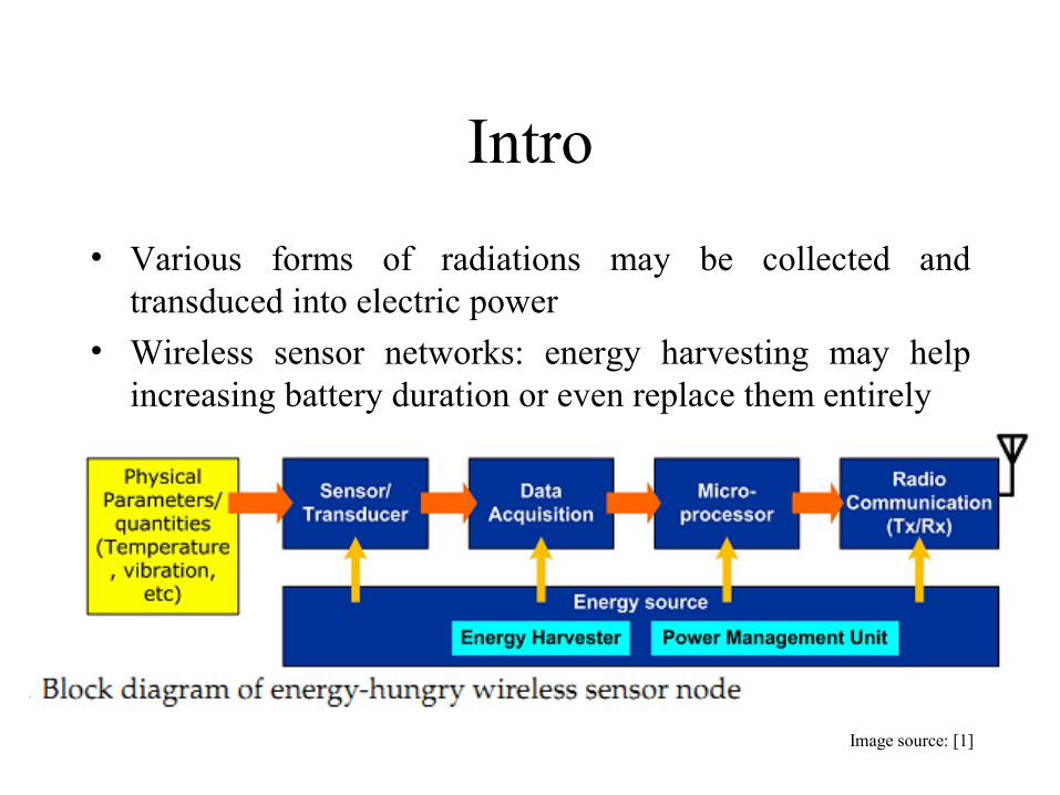
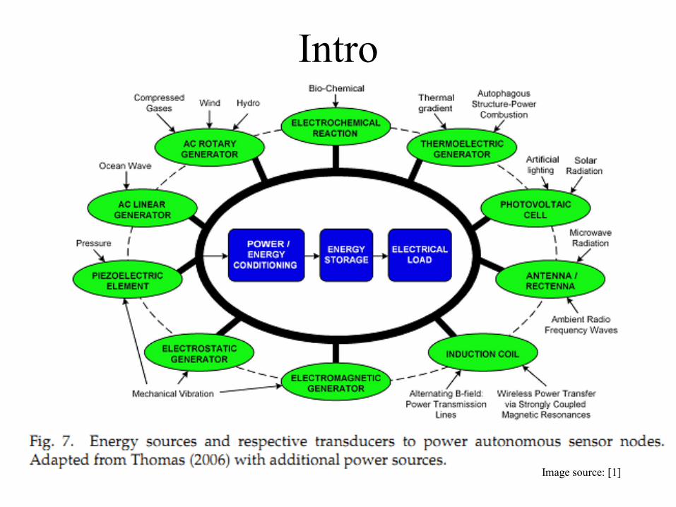
Intro• Various forms of radiations may be collected and
transduced into electric power• Wireless sensor networks: energy harvesting may help
increasing battery duration or even replace them entirely
Image source: [1]
Intro
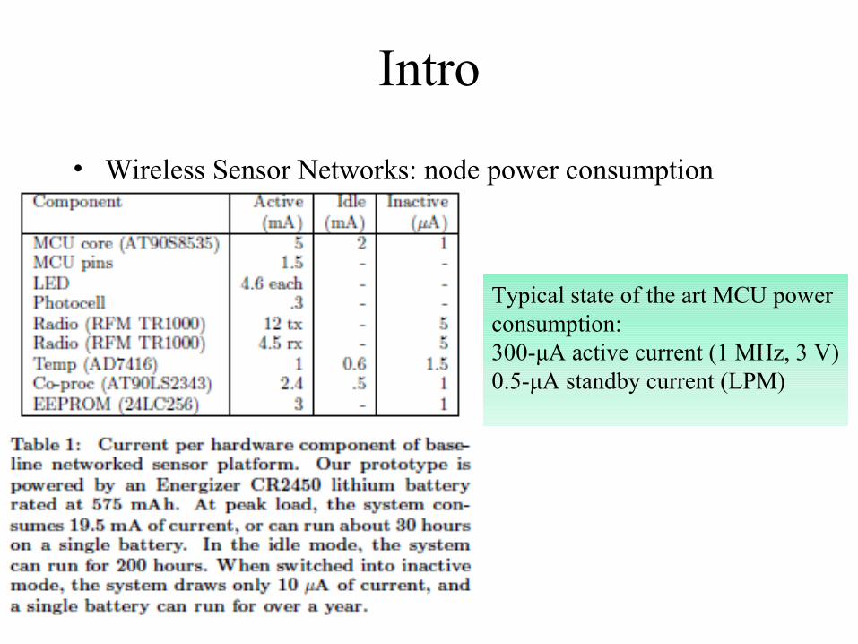
• Wireless Sensor Networks: node power consumption
Typical state of the art MCU power consumption:300-μA active current (1 MHz, 3 V)0.5-μA standby current (LPM)
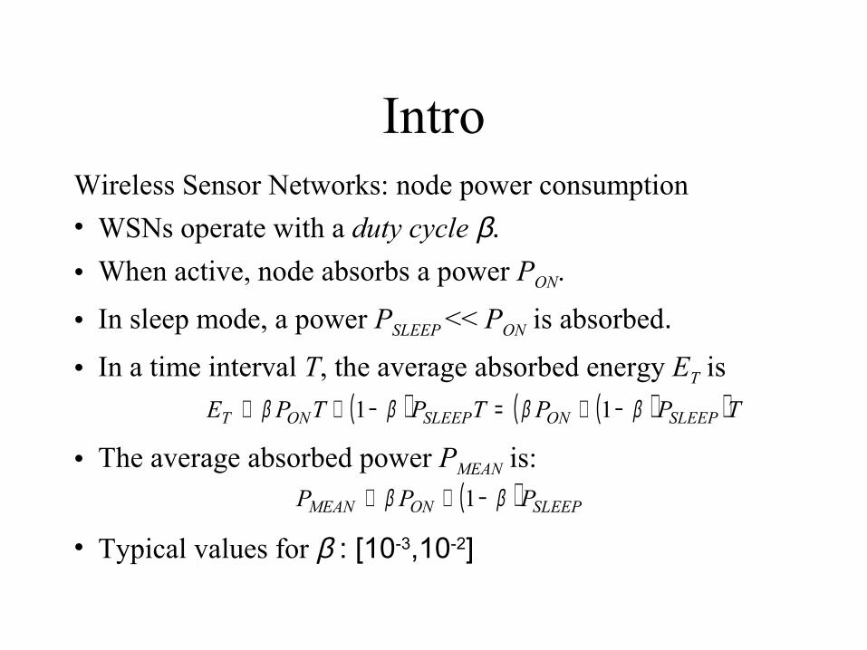
IntroWireless Sensor Networks: node power consumption• WSNs operate with a duty cycle β.• When active, node absorbs a power PON.
• In sleep mode, a power PSLEEP << PON is absorbed.
• In a time interval T, the average absorbed energy ET is
• The average absorbed power PMEAN is:
• Typical values for β : [10-3,10-2]
( ) ( )( )TPPTPTPE SLEEPONSLEEPONT ββββ −+=−+≅ 11
( ) SLEEPONMEAN PPP ββ −+≅ 1

IntroWireless Sensor Networks: node power consumption• 1.5 V AA alcaline battery (3000 mAh).
• When active, node absorbs 20 mA DC (PON=30 mW)
• In sleep mode, node absorbs 10 nA DC (PSLEEP =15 nW).
• With β =0.01 the average absorbed power PMEAN is:
• With β =0.01 the battery duration is:
( )( ) days625s104.5μW300kJ2.16
17 ≅⋅==
−+=
SLEEPON
TPP
ETββ
( ) μW3001 ≅−+≅ SLEEPONMEAN PPP ββ
J16200s3600mA3000V5.1 ≅⋅⋅=TE
Intro
Image source: [1]

Intro
Main metrics for renewable power generation/storage technologies: • Power density (peak power), energy density, per mass/volume unit (Photovoltaic: 100 µW/cm3-100 mW/cm3, other non radiant sources are in the tens of µW/cm3 range)• Conversion/Transfer Efficiency

LF Radiation Harvesting• Basics: LF harvesting often relies on inductive powering
(Es: rechargeable tootbrushes, RFID)• Magnetic coupling between a primary and a secondary coil• Safe technology (Galvanic insulation)
Image source: [3]
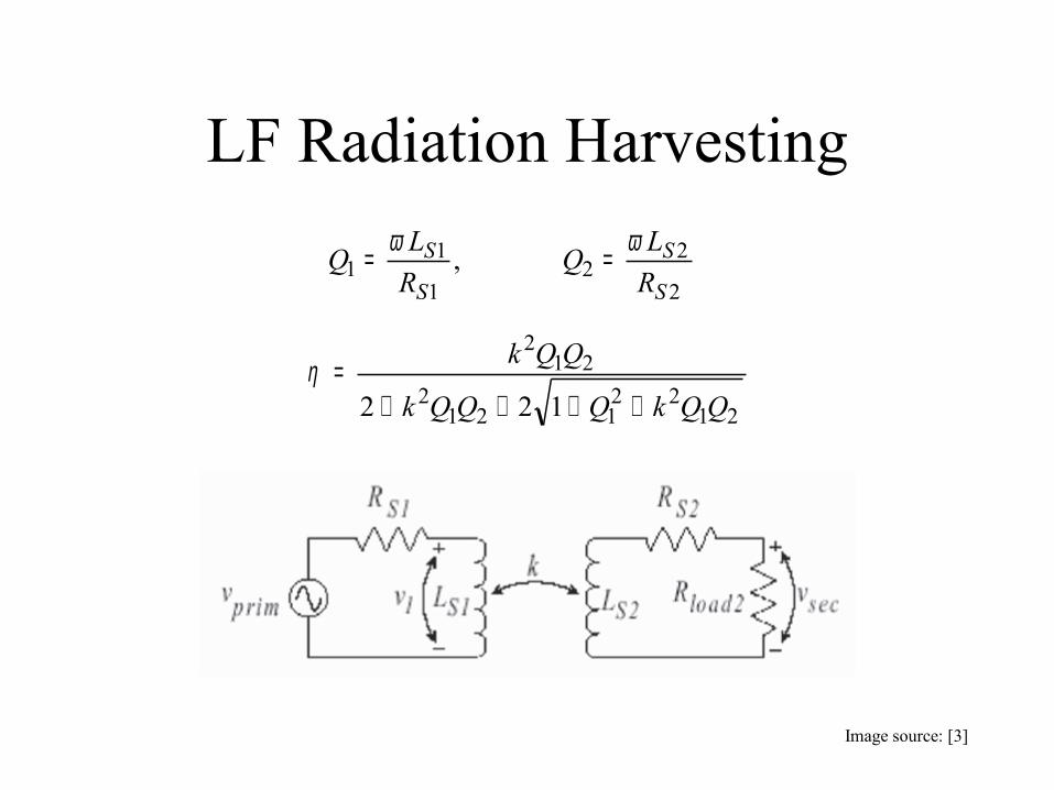
LF Radiation Harvesting
2
22
1
11 ,
S
S
S
SRLQ
RLQ ωω ==
2122
1212
212
122 QQkQQQk
QQk
++++=η
Image source: [3]

LF Radiation Harvesting• Efficiency grows with Q factor of both coils (can exceed
80%) and with mutual coupling k• May require high currents in the primary• Short range (near field), using resonant circuits helps
increasing efficiency and range
Image source: [3]
RF Radiation Harvesting• Basics• Rectenna• Cockroft-Walton multiplier

Basics• Main idea: collect energy from RF waves.• “Ad Hoc” RF sources (Es: RFID, military applications,
satellite based power source).• “Unintentional” sources (Radio or TV broadcasting, Cell
phone base stations, solar radiation…).• Italy: FM Radio, 98-108 MHz
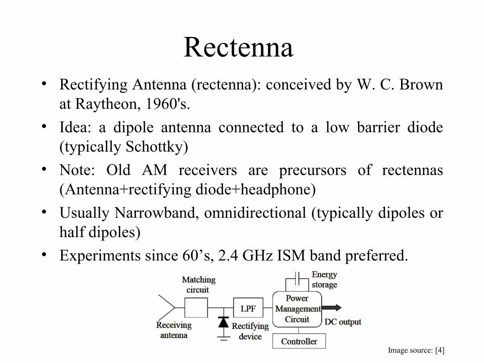
Rectenna • Rectifying Antenna (rectenna): conceived by W. C. Brown
at Raytheon, 1960's.• Idea: a dipole antenna connected to a low barrier diode
(typically Schottky)• Note: Old AM receivers are precursors of rectennas
(Antenna+rectifying diode+headphone)• Usually Narrowband, omnidirectional (typically dipoles or
half dipoles)• Experiments since 60’s, 2.4 GHz ISM band preferred.
Image source: [4]
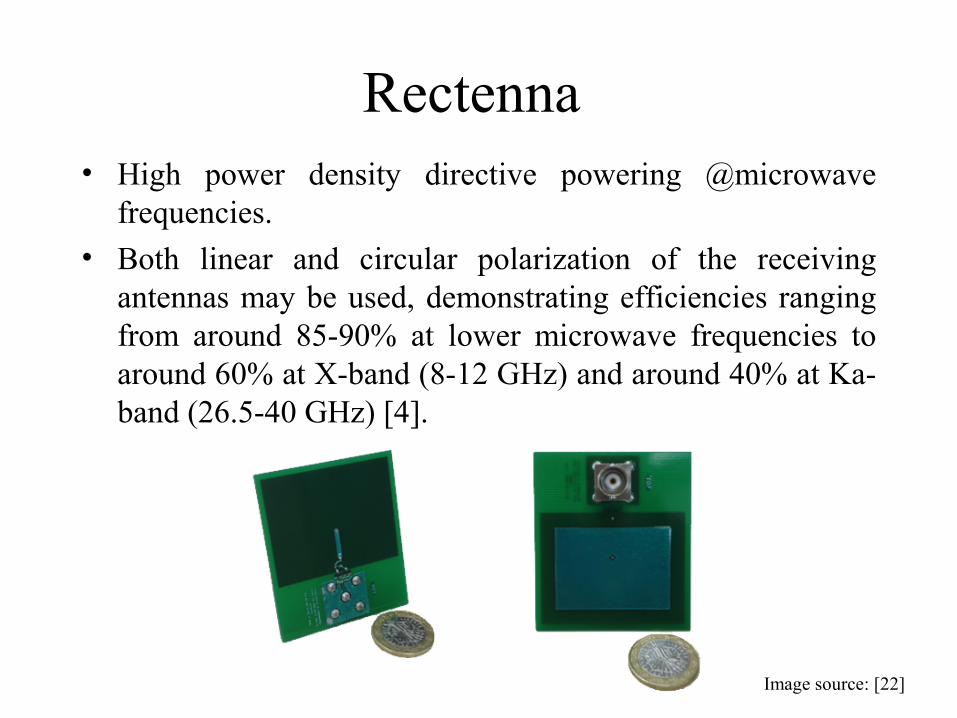
Rectenna • High power density directive powering @microwave
frequencies.• Both linear and circular polarization of the receiving
antennas may be used, demonstrating efficiencies ranging from around 85-90% at lower microwave frequencies to around 60% at X-band (8-12 GHz) and around 40% at Ka-band (26.5-40 GHz) [4].
Image source: [22]

Rectenna
• Available power: low (microwatt). Expected power densities @ 50 meters from a typical base-station tower operating at 880 and 1990 MHz, are typically around 10-4 mW/cm2. [4]
• The rectenna output power depends on the power flux density, frequency, incident angle of microwave, and rectifying circuit performance.
• Output voltage: low (mV)
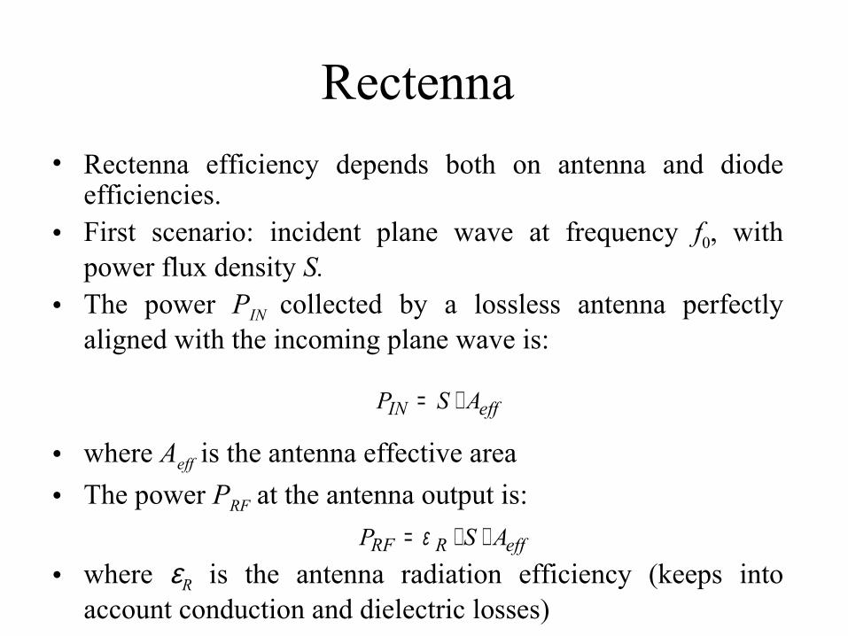
Rectenna • Rectenna efficiency depends both on antenna and diode
efficiencies.• First scenario: incident plane wave at frequency f0, with
power flux density S.• The power PIN collected by a lossless antenna perfectly
aligned with the incoming plane wave is:
• where Aeff is the antenna effective area• The power PRF at the antenna output is:
• where εR is the antenna radiation efficiency (keeps into account conduction and dielectric losses)
effIN ASP ⋅=
effRRF ASP ⋅⋅= ε
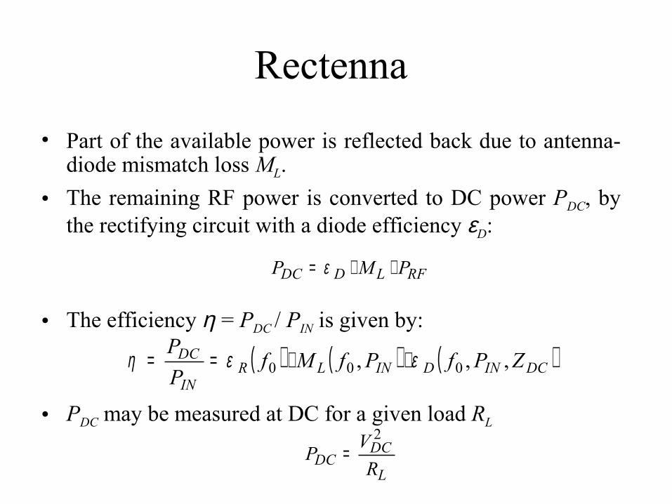
Rectenna
• Part of the available power is reflected back due to antenna-diode mismatch loss ML.
• The remaining RF power is converted to DC power PDC, by the rectifying circuit with a diode efficiency εD:
• The efficiency η = PDC / PIN is given by:
• PDC may be measured at DC for a given load RL
RFLDDC PMP ⋅⋅= ε
( ) ( ) ( )DCINDINLRIN
DC ZPfPfMfPP
,,, 000 εεη ⋅⋅==
L
DCDC R
VP2
=
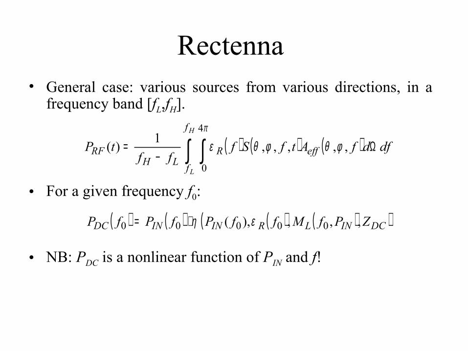
Rectenna • General case: various sources from various directions, in a
frequency band [fL,fH].
• For a given frequency f0:
• NB: PDC is a nonlinear function of PIN and f!
( ) ( ) ( ) dfdfAtfSfff
tP eff
f
fR
LHRF
H
L
Ω−
= ∫ ∫ ,,,,,1)(4
0
φθφθεπ
( ) ( ) ( ) ( )( )DCINLRININDC ZPfMffPfPfP ,,,),( 00000 εη⋅=
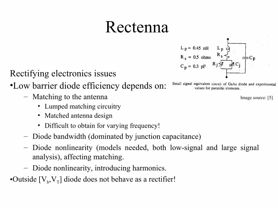
Rectenna
Rectifying electronics issues•Low barrier diode efficiency depends on:
– Matching to the antenna• Lumped matching circuitry• Matched antenna design• Difficult to obtain for varying frequency!
– Diode bandwidth (dominated by junction capacitance)– Diode nonlinearity (models needed, both low-signal and large signal
analysis), affecting matching.– Diode nonlinearity, introducing harmonics.
•Outside [Vb,VT] diode does not behave as a rectifier!
Image source: [5]

Rectenna • Overall diode efficiency:
Image source: [4,24]
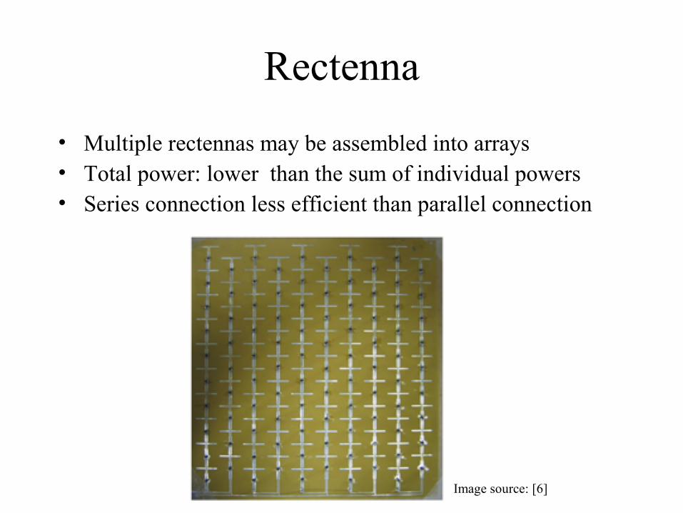
Rectenna
• Multiple rectennas may be assembled into arrays• Total power: lower than the sum of individual powers• Series connection less efficient than parallel connection
Image source: [6]
Cockroft-Walton Multiplier
• Antenna output voltage may be very low, about a very few hundreds of millivolts (when scavenging RF from commercial broadcasting).
• Usable voltage must exceed 1 V (low power )• A single rectifying diode may be inefficient• Transformers are bulky, with insufficient bandwidth (a few
hundreds of MHz)

Cockroft-Walton Multiplier
• Cockroft-Walton multiplier: originally developed for high energy physics;
Image source: Wikipedia
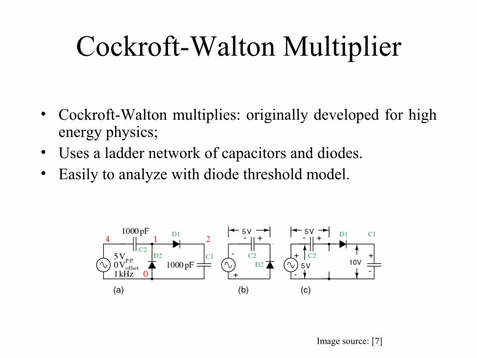
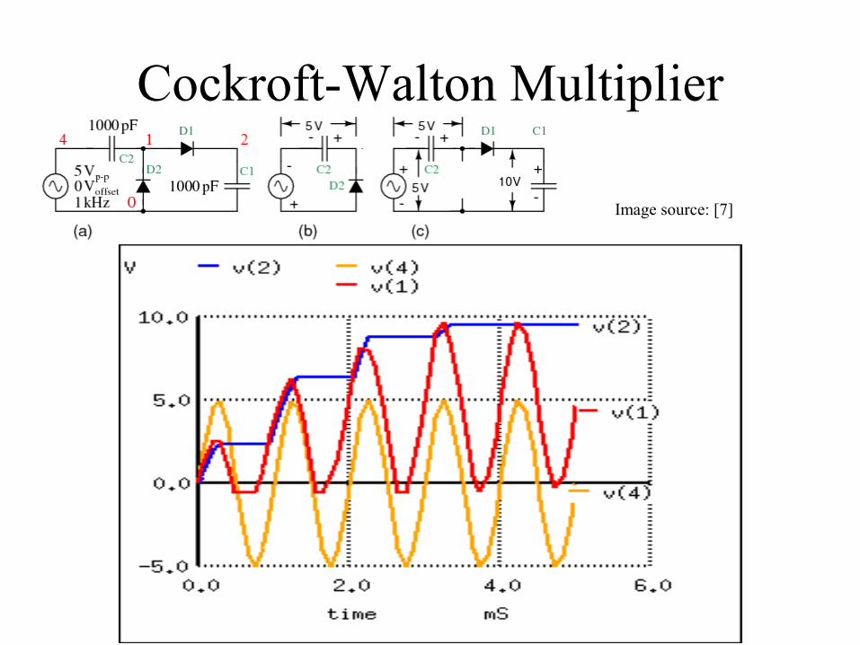
Cockroft-Walton Multiplier
• Cockroft-Walton multiplies: originally developed for high energy physics;
• Uses a ladder network of capacitors and diodes.• Easily to analyze with diode threshold model.
Image source: [7]

Cockroft-Walton Multiplier
• (a): full circuit• (b): negative half wave equivalent circuit• (c): positive halfwave equivalent circuit.• Power scavenging requires low barrier voltage
Image source: [7]
Cockroft-Walton Multiplier
Image source: [7]

Cockroft-Walton Multiplier
• Several multipliers may be cascaded for higher multiplying factor
• Load insertion usually reduces output voltage with respect to open circuit conditions
• Diode power consumption and losses limit the number of stages
Image source: [7]
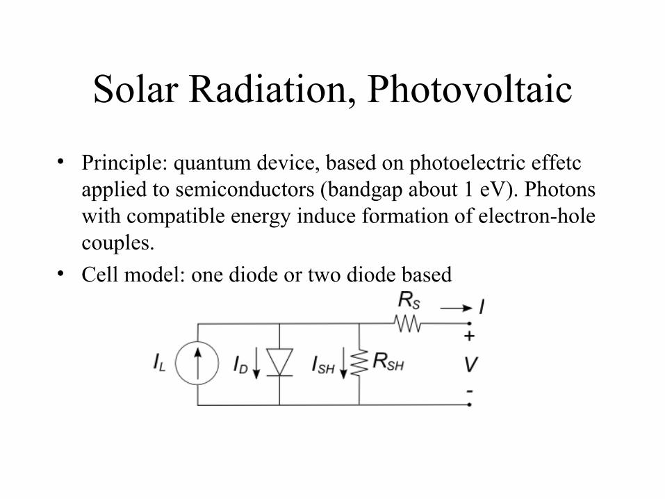
Solar Radiation, Photovoltaic• Principle: quantum device, based on photoelectric effetc
applied to semiconductors (bandgap about 1 eV). Photons with compatible energy induce formation of electron-hole couples.
• Cell model: one diode or two diode based

Basics and PV Cell Modeling• Theoretical Efficiency given by Shockley-Queisser Limit:
<30% single p-n junction, <55% 2-junctions, 86% asymptotic.
• Limiting factors: blackbody radiation, recombination, spectrum losses.
• Efficiency may be increased in several ways (Concentration, tandem cells, infrared capture, fluorescent down-conversion, impurities/intermediate band…) [23].
• May be connected into arrays (series: less efficient in presence of partial shading).
• Actual efficiency: about 20% single junction, 40% multi-junction.
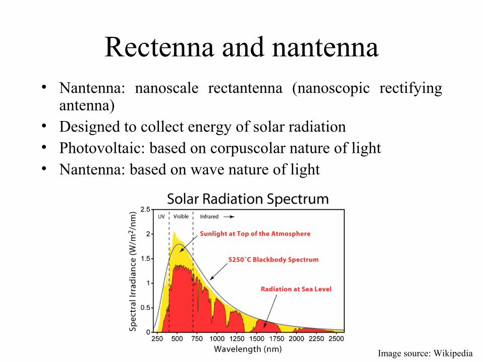
Rectenna and nantenna• Nantenna: nanoscale rectantenna (nanoscopic rectifying
antenna)• Designed to collect energy of solar radiation• Photovoltaic: based on corpuscolar nature of light• Nantenna: based on wave nature of light
Image source: Wikipedia
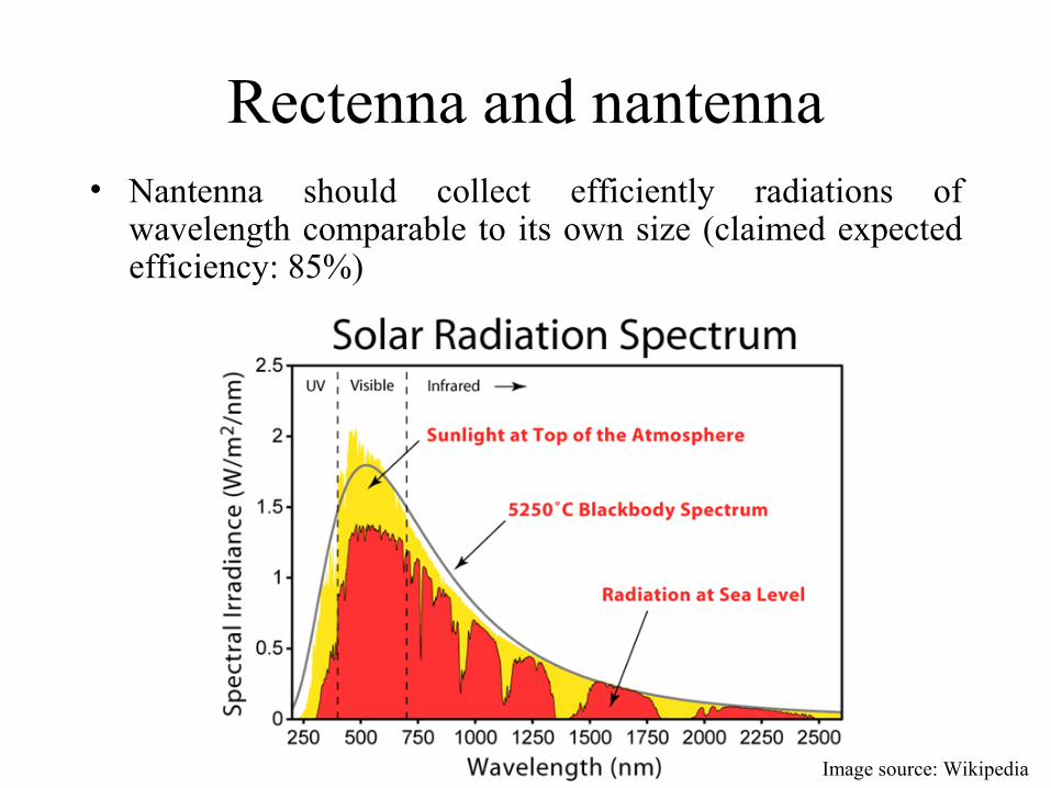
Rectenna and nantenna• Nantenna should collect efficiently radiations of
wavelength comparable to its own size (claimed expected efficiency: 85%)
Image source: Wikipedia

Rectenna and nantenna• Implementing an array of variously sized nantennas is
potentially much easier than implementing an array of semiconductor alloys with various bandgaps.
Image source: Wikipedia
Rectenna and nantenna• nantennas radiation diagram may be exploited to reduce
tracking requirements.

Rectenna and nantenna• Some nantenna open issues (deviation from rectantenna
assumptions):• Efficiency prediction is not fully theoretically established;• Mostly surface current conduction due to skin effect (non
ohmic material, increased resistance);
• Copper (σ≅1.68×10⁻⁸ Ω·m, µr ≅1) @200 THz: δ≅4.6 nm• Standard photolithography is not (yet…) mature for
nanometer form factor (requires electron beam litography, more expensive).
rrr
d
S fffeJJ
µσ
µπσ
µµπσ
ω µσδδ 3.503
104222, 72
0≅≅=== −
−
Rectenna and nantenna• Some nantenna open issues (continued):• Schottky diodes work satisfactorily up to 5 THz, 0.4-1.6
µm wavelengths (maximum solar irradiance) correspond to 187-750 THz. Diode junction capacitance will reduce power conversion efficiency (THz require attoFarad capacitance);
• Metal Insulator Metal (MIM) tunneling diodes are currently being studied to increase bandwidth;
• Currently developed nantennas mostly work in the infrared (8-10 µm wavelengths), and perform much below the expected conversion efficiency.
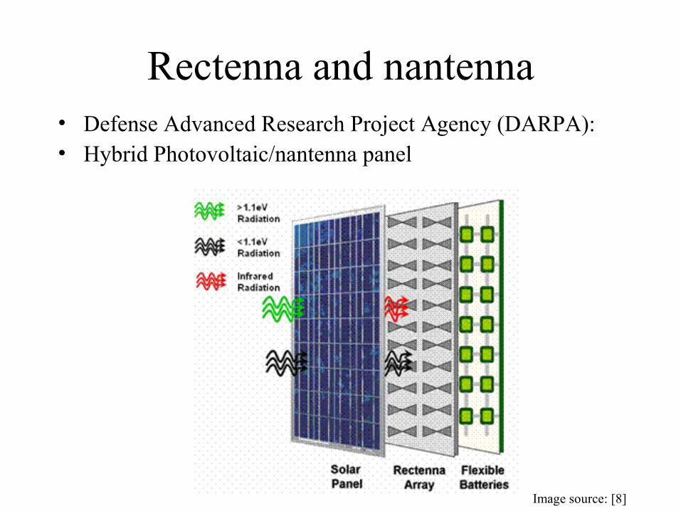
Rectenna and nantenna• Defense Advanced Research Project Agency (DARPA):• Hybrid Photovoltaic/nantenna panel
Image source: [8]
References1. Intech “Sustainable Wireless Sensor Networks”, Chapter 22. Jin Fang, Hugo Frederich, Laurent Pilon, Harvesting Nanoscale Thermal
Radiation Using Pyroelectric Materials," ASME Journal of Heat Transfer, 2010
3. M. Steyaert et al. (eds), «Wireless Inductive Transfer of Power and Data» Analog Circuit Design, 395–414, 2006 Springer.
4. Gianfranco Andìa Vera, "Efficient Rectenna Design for Ambient Microwave Energy Recycling", Doctoral Thesis, available online.
5. J. O. Mc Spadden, T. Yoo, K. Chang, “Theoretical and Experimental Investigations of a Rectenna Element for Microwave Power Transmissions”, IEEE Trans. on Microwave Theory and Techniques, Vol. 40, no. 12, Dec. 1992.
6. http://smartmatech.com/eng/tech/images/rectenna_23.jpg7. http://www.allaboutcircuits.com/vol_3/chpt_3/8.html

References8. http://www.coolcadelectronics.com/DARPA_Energy_Harvesting.html 9. http://en.wikipedia.org/wiki/Energy_harvesting 10. http://en.wikipedia.org/wiki/Dye-sensitized_solar_cell11. http://en.wikipedia.org/wiki/Shockley%E2%80%93Queisser_limit12. http://4hv.org/e107_plugins/forum/forum_viewtopic.php?2435113. http://www.technologyreview.com/communications/22764/14. http://www.thescienceforum.com/physics/18894-harvesting-energy-
radiation.html 15. http://scientiareview.org/pdfs/176.pdf 16. http://smartmatech.com/eng/tech/rectenna.html17. http://en.wikipedia.org/wiki/Nantenna
Image sourcesVarious18. http://www.scribd.com/doc/54333065/14/Recent-Technologies-of-
Rectenna19. http://www.inl.gov/pdfs/nantenna.pdf 20. http://www.ece.nus.edu.sg/emdl/yenkheng.htm21. http://www.micropelt.com/down/pm_te_power_node_engl.pdf 22. http://www.enesio.fr/savoir/rectenna.php23. Martin Green, Third Generation Photovoltaics: Advanced Solar Energy
Conversion, Springer.24. Yoo, T. and K. Chang, “Theoretical and Experimental Development of 10
and 35 GHz Rectenna”,IEEE Trans. MTT, Vol. 40, No. 6, 1992, pp.1259-1266.