Embed Size (px)
Citation preview
MorphoSmart(TM) Installation Guide (MSO20x, MSO3xx, MSO13x0)
Sagem Sécurité
MorphoSmart(TM) Installation Guide
(MSO20x, MSO3xx, MSO13x0) Version 2.8 May 2008
Produced by Sagem Sécurité Headquarters : 27, rue Leblanc 75512 PARIS CEDEX 12 FRANCE Customer Service : Sagem Sécurité SAV Terminaux Biométriques Boulevard Lénine - BP428 76805 Saint Etienne du Rouvray FRANCE Tel : +33 2 35 64 55 05 Hotline : Sagem Sécurité Support terminaux biométriques 24, Av du gros chêne 95610 ERAGNY - FRANCE [email protected] : +33 1 58 11 39 19 www.biometric-terminals.com Copyright ©2007 Sagem Sécurité http://www.sagem-securite.com/
Version 2.8 May 2008 Sagem Sécurité Document - Reproduction and disclosure prohibited 1-1
MorphoSmart(TM) Installation Guide (MSO20x, MSO3xx, MSO13x0)
Sagem Sécurité
Copyright notices
Copyrights 2002-2008, SAGEM Sécurité, All rights reserved.
Information in this document is subject to change without notice and does norepresent a commitment on the part of SAGEM Sécurité. No part of this documenmay be reproduced or transmitted in any form or by any means, electronic omechanical, including photocopying or recording, for any purpose without theexpress written permission of SAGEM Sécurité.
The software described in this document is supplied under a license agreement onondisclosure agreement. It is against the law to copy the software on anymedium except as specifically allowed in the agreement.
This manual makes reference to names and products that are trademarks of theirespective owners.
MORPHO® is a registered trademark of SAGEM Sécurité.
Version 2.8 May 2008 Sagem Sécurité Document - Reproduction and disclosure prohibited
1-2
MorphoSmart(TM) Installation Guide (MSO20x, MSO3xx, MSO13x0)
Sagem Sécurité
Version 2.8 May 2008 Sagem Sécurité Document - Reproduction and disclosure prohibited 1-3
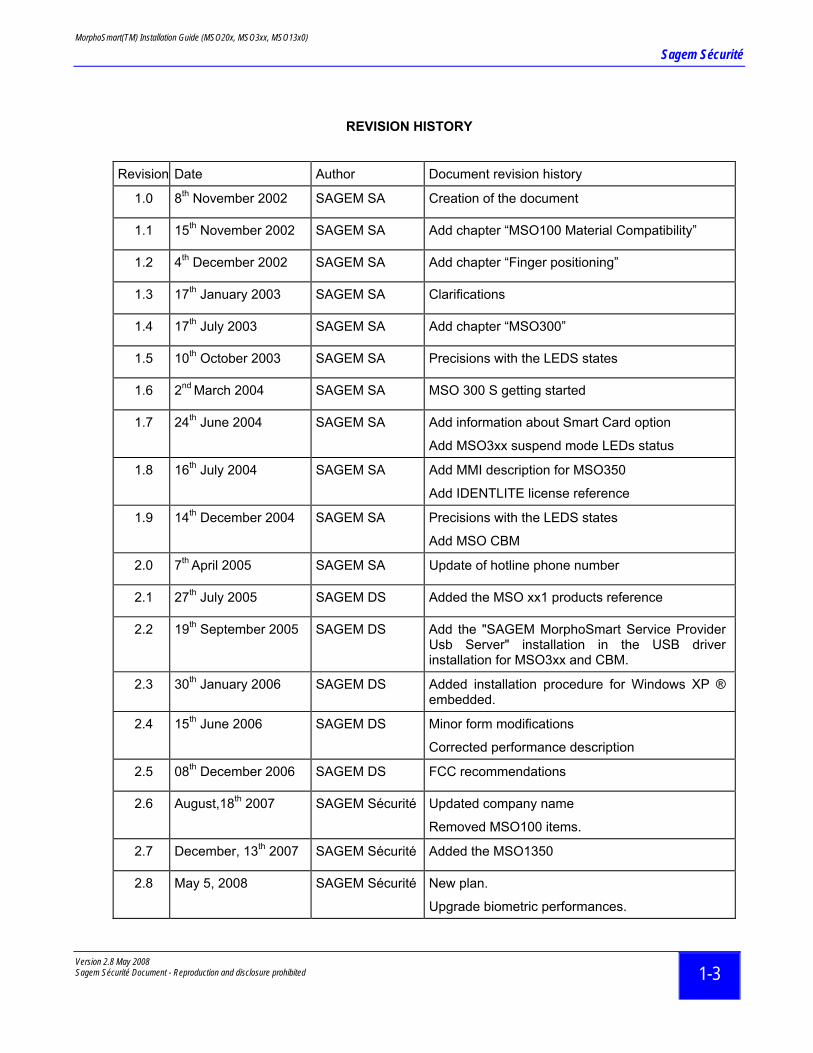
REVISION HISTORY
Revision Date Author Document revision history
1.0 8th November 2002 SAGEM SA Creation of the document
1.1 15th November 2002 SAGEM SA Add chapter “MSO100 Material Compatibility”
1.2 4th December 2002 SAGEM SA Add chapter “Finger positioning”
1.3 17th January 2003 SAGEM SA Clarifications
1.4 17th July 2003 SAGEM SA Add chapter “MSO300”
1.5 10th October 2003 SAGEM SA Precisions with the LEDS states
1.6 2nd March 2004 SAGEM SA MSO 300 S getting started
1.7 24th June 2004 SAGEM SA Add information about Smart Card option
Add MSO3xx suspend mode LEDs status
1.8 16th July 2004 SAGEM SA Add MMI description for MSO350
Add IDENTLITE license reference
1.9 14th December 2004 SAGEM SA Precisions with the LEDS states
Add MSO CBM
2.0 7th April 2005 SAGEM SA Update of hotline phone number
2.1 27th July 2005 SAGEM DS Added the MSO xx1 products reference
2.2 19th September 2005 SAGEM DS Add the "SAGEM MorphoSmart Service Provider Usb Server" installation in the USB driver installation for MSO3xx and CBM.
2.3 30th January 2006 SAGEM DS Added installation procedure for Windows XP ® embedded.
2.4 15th June 2006 SAGEM DS Minor form modifications
Corrected performance description
2.5 08th December 2006 SAGEM DS FCC recommendations
2.6 August,18th 2007 SAGEM Sécurité Updated company name
Removed MSO100 items.
2.7 December, 13th 2007 SAGEM Sécurité Added the MSO1350
2.8 May 5, 2008 SAGEM Sécurité New plan.
Upgrade biometric performances.

MorphoSmart(TM) Installation Guide (MSO20x, MSO3xx, MSO13x0)
Sagem Sécurité
Version 2.8 May 2008 Sagem Sécurité Document - Reproduction and disclosure prohibited
1-4
MorphoSmart(TM) Installation Guide (MSO20x, MSO3xx, MSO13x0)
Sagem Sécurité
Version 2.8 May 2008 Sagem Sécurité Document - Reproduction and disclosure prohibited 1-5
TABLE OF CONTENTS
1 OVERVIEW.................................................................................................................................................. 1-7
1.1 WELCOME TO MORPHOSMART™ ........................................................................................................... 1-7 1.2 CONTENTS ............................................................................................................................................ 1-7
2 MORPHOSMARTTM DEVICE INSTALLATION .......................................................................................... 2-8
2.1 SAFETY INSTRUCTIONS .......................................................................................................................... 2-8 2.2 MORPHOSMARTTM HARDWARE PLATFORM COMPATIBILITY ...................................................................... 2-8 2.3 HOST SYSTEM IS A WINDOWS™ PC ....................................................................................................... 2-8 2.4 HOST SYSTEM IS NOT A WINDOWS™ PC ................................................................................................ 2-9
3 MORPHOSMART™ USB DRIVER INSTALLATION ............................................................................... 3-10
3.1 MORPHOSMART™ USB DRIVER SETUP................................................................................................ 3-10 3.2 IMPORTANT NOTICE ............................................................................................................................. 3-10 3.3 WINDOWS XP ® EMBEDDED ................................................................................................................ 3-10
4 FINGER PLACEMENT RULES................................................................................................................. 4-11
5 MORPHOSMARTTM MSO20X................................................................................................................... 5-12
5.1 PHYSICAL CHARACTERISTICS ............................................................................................................... 5-12 5.2 SAFETY INSTRUCTIONS ........................................................................................................................ 5-12 5.3 GENERAL DESCRIPTION ....................................................................................................................... 5-13
6 MORPHOSMARTTM MSO3XX .................................................................................................................. 6-14
6.1 PHYSICAL CHARACTERISTICS ............................................................................................................... 6-14 6.2 GENERAL DESCRIPTION........................................................................................................................ 6-15
7 MORPHOSMARTTM MSOXX1 : FAKE FINGER DETECTION................................................................. 7-16
7.1 MORPHOSMARTTM MSOXX1 DEVICES .................................................................................................. 7-16 7.2 SPECIFIC RECOMMENDATIONS.............................................................................................................. 7-16 7.3 CLEANING PRECAUTIONS ..................................................................................................................... 7-16
8 MORPHOSMARTTM MSO1300 ................................................................................................................. 8-17
8.1 PHYSICAL CHARACTERISTICS ............................................................................................................... 8-17 8.2 GENERAL DESCRIPTION........................................................................................................................ 8-17
9 MORPHOSMARTTM MSO1350 ................................................................................................................. 9-19
9.1 PHYSICAL CHARACTERISTICS ............................................................................................................... 9-19
MorphoSmart(TM) Installation Guide (MSO20x, MSO3xx, MSO13x0)
Sagem Sécurité
Version 2.8 May 2008 Sagem Sécurité Document - Reproduction and disclosure prohibited
1-6
9.2 GENERAL DESCRIPTION........................................................................................................................ 9-20
10 MORPHOSMARTTM DEVICE TECHNICAL CHARACTERISTICS ........................................................ 10-21
10.1 PHYSICALS CHARACTERISTICS............................................................................................................ 10-21 10.2 BIOMETRIC CHARACTERISTICS............................................................................................................ 10-22
11 MAN MACHINE INTERFACE ................................................................................................................. 11-24
11.1 MSO2XX/MSO3XX MAN MACHINE INTERFACE ................................................................................... 11-24 11.2 MSO13XX MAN MACHINE INTERFACE ................................................................................................ 11-26
12 SECURE MORPHOSMART™ GETTING STARTED............................................................................. 12-27
13 RECOMMENDATIONS ........................................................................................................................... 13-28
14 FCC STANDARD .................................................................................................................................... 14-29
15 TABLE OF FIGURES.............................................................................................................................. 15-30
MorphoSmart(TM) Installation Guide (MSO20x, MSO3xx, MSO13x0)
Sagem Sécurité
Version 2.8 May 2008 Sagem Sécurité Document - Reproduction and disclosure prohibited 1-7
1 Overview
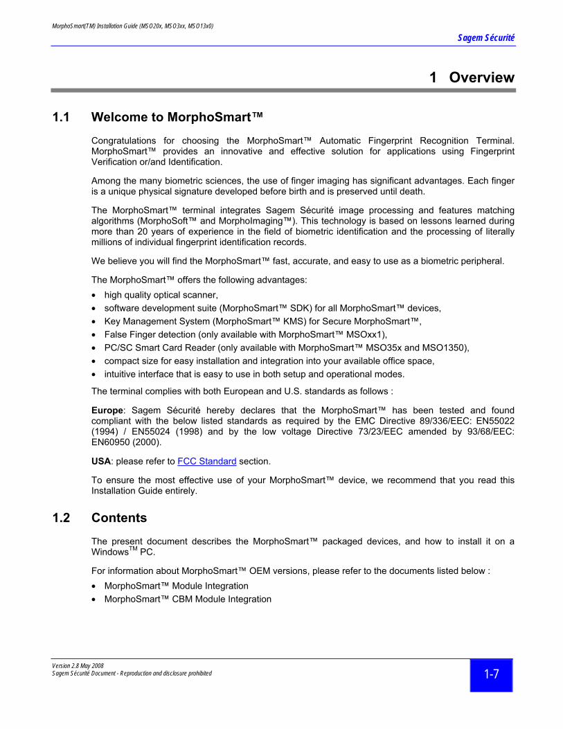
1.1 Welcome to MorphoSmart™
Congratulations for choosing the MorphoSmart™ Automatic Fingerprint Recognition Terminal. MorphoSmart™ provides an innovative and effective solution for applications using Fingerprint Verification or/and Identification.
Among the many biometric sciences, the use of finger imaging has significant advantages. Each finger is a unique physical signature developed before birth and is preserved until death.
The MorphoSmart™ terminal integrates Sagem Sécurité image processing and features matching algorithms (MorphoSoft™ and MorphoImaging™). This technology is based on lessons learned during more than 20 years of experience in the field of biometric identification and the processing of literally millions of individual fingerprint identification records.
We believe you will find the MorphoSmart™ fast, accurate, and easy to use as a biometric peripheral.
The MorphoSmart™ offers the following advantages: • high quality optical scanner, • software development suite (MorphoSmart™ SDK) for all MorphoSmart™ devices, • Key Management System (MorphoSmart™ KMS) for Secure MorphoSmart™, • False Finger detection (only available with MorphoSmart™ MSOxx1), • PC/SC Smart Card Reader (only available with MorphoSmart™ MSO35x and MSO1350), • compact size for easy installation and integration into your available office space, • intuitive interface that is easy to use in both setup and operational modes.
The terminal complies with both European and U.S. standards as follows :
Europe: Sagem Sécurité hereby declares that the MorphoSmart™ has been tested and found compliant with the below listed standards as required by the EMC Directive 89/336/EEC: EN55022 (1994) / EN55024 (1998) and by the low voltage Directive 73/23/EEC amended by 93/68/EEC: EN60950 (2000).
USA: please refer to FCC Standard section.
To ensure the most effective use of your MorphoSmart™ device, we recommend that you read this Installation Guide entirely.
1.2 Contents
The present document describes the MorphoSmart™ packaged devices, and how to install it on a WindowsTM PC.
For information about MorphoSmart™ OEM versions, please refer to the documents listed below : • MorphoSmart™ Module Integration • MorphoSmart™ CBM Module Integration
MorphoSmart(TM) Installation Guide (MSO20x, MSO3xx, MSO13x0)
Sagem Sécurité
Version 2.8 May 2008 Sagem Sécurité Document - Reproduction and disclosure prohibited
2-8
2 MorphoSmartTM device installation
2.1 Safety instructions
The MorphoSmart™ is intended for indoor use only.
The MorphoSmart™ must be placed on a flat clear surface where it will not be at risk of coming in contact with fluids.
2.2 MorphoSmartTM Hardware Platform Compatibility
The MorphoSmart™ USB devices are compatible with usual PC configurations, but we therefore strongly advise you to perform a compatibility test with target PC hardware configuration.
The MorphoSmart™ USB devices are compatible with most of the self-powered USB hub available. But we also recommend to perform a compatibility test with target USB Hub.
Please note that USB hub powered only by the USB port, could provide not enough power supply for a normal function of MorphoSmart™ USB devices.
2.3 Host system is a Windows™ PC
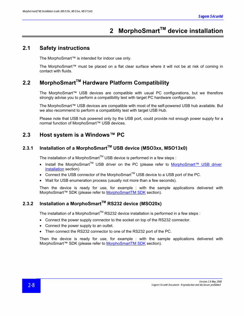
2.3.1 Installation of a MorphoSmartTM USB device (MSO3xx, MSO13x0)
The installation of a MorphoSmartTM USB device is performed in a few steps : • Install the MorphoSmartTM USB driver on the PC (please refer to MorphoSmart™ USB driver
installation section) • Connect the USB connector of the MorphoSmartTM USB device to a USB port of the PC. • Wait for USB enumeration process (usually not more than a few seconds).
Then the device is ready for use, for example : with the sample applications delivered with MorphoSmart™ SDK (please refer to MorphoSmartTM SDK section).
2.3.2 Installation a MorphoSmartTM RS232 device (MSO20x)
The installation of a MorphoSmartTM RS232 device installation is performed in a few steps : • Connect the power supply connector to the socket on top of the RS232 connector. • Connect the power supply to an outlet. • Then connect the RS232 connector to one of the RS232 port of the PC.
Then the device is ready for use, for example : with the sample applications delivered with MorphoSmart™ SDK (please refer to MorphoSmartTM SDK section).
MorphoSmart(TM) Installation Guide (MSO20x, MSO3xx, MSO13x0)
Sagem Sécurité
Version 2.8 May 2008 Sagem Sécurité Document - Reproduction and disclosure prohibited 2-9
2.3.3 MorphoSmartTM SDK
The MorphoSmart™ Software Development Kit, provides the required elements to enable you to develop your own applications for MorphoSmart™ devices. It is a usually delivered on a CDROM which contains : • all the documentation required for MorphoSmartTM devices use and integration, • the MorphoSmartTM USB driver for WindowsTM PC, • sample applications which enables to demonstrate the MorphoSmartTM functions • source files of sample applications • libraries (dll) and ActiveX with MorphoSmartTM device functions
To evaluate a MorphoSmart™ device we recommend to install the MorphoSmart™ Software Development Kit on a WindowsTM PC : • insert the MorphoSmart™ SDK CD-ROM into the drive, • if the installation process doesn’t start automatically, double click on the Setup.exe file to start it, • install MorphoSmart™ USB driver before connecting a MorphoSmart™ USB device, • connect the MorphoSmart™ device to a USB port, or to a RS232 port (MSO20x only), • run MSO_Login.exe or MSO_Demo.exe sample application, • select the MorphoSmart™ device to use, • try MorphoSmart™ device functions.
For more information on the MorphoSmart™ Software Development Kit, please refer to the MorphoSmart Programmer Guide document.
2.4 Host system is not a Windows™ PC
2.4.1 RS232 connection
The MorphoSmart™ MSO200 can be physically connected to other host than Windows™ PC, but the ‘MorphoSmart™ communication protocol over RS232’ must be developed for the host system.
The ‘MorphoSmart™ communication protocol over RS232’, is described in the MorphoSmart Host System Interface specification document. And a sample of development of this protocol, with C language source files, is provided the MorphoSmart™ SDK.
2.4.2 USB connection
A MorphoSmart™ USB device can be physically connected to other host than Windows™ PC, but the ‘MorphoSmart™ communication protocol over USB’ and a compatible USB driver must be developed for the host system.
The integrated USB driver of the MorphoSmart™ terminal emulates a RS232 serial port. The MorphoSmart™ terminal is processed as a Communication Device Class (CDC), in accordance with the "USB Device Class Specifications, version 1.1" available from the www.usb.org web site, in "developers, documents" section. The device may also be used with a USB2.0 controller, but will still use the USB 1.1 full speed transfer rate (12 Mbits/s).
The ‘MorphoSmart™ communication protocol over USB’, is described in the MorphoSmart Host System Interface specification document.
MorphoSmart(TM) Installation Guide (MSO20x, MSO3xx, MSO13x0)
Sagem Sécurité
Version 2.8 May 2008 Sagem Sécurité Document - Reproduction and disclosure prohibited
3-10
3 MorphoSmart™ USB driver installation
3.1 MorphoSmart™ USB driver setup
The MorphoSmart™ USB driver can be installed from MorphoSmart™ SDK, when it is installed.
For MorphoSmart™ SDK V4.0.3.0 (and later versions), the USB driver installation installs and starts the "SAGEM MorphoSmart Service Provider Usb Server" too. • Start the MorphoSmart™ USB driver installation from the MorphoSmart™ SDK PROGRAMS
folders in the windows start menu: START / PROGRAMS / MorphoSmart SDK / PC / Drivers / Install (Desinstall) the USB driver for MorphoSmart
• Use the Next and Back buttons to navigate through the wizard. • Plug the MorphoSmart™ USB device to an available USB port on your PC with the supplied USB
cord.
3.2 Important Notice
MorphoSmart™ USB devices are currently compatible with Windows 2000 SP4, Windows XP Professional Edition SP2 and Windows Server 2003 Enterprise.
Administrator rights on your local computer are required when plugging the MorphoSmart™ USB device for the first time.
3.3 Windows XP ® Embedded Note for Windows XP ® Embedded:
If you are using Windows XP ® Embedded, the automatic installer based on MSI won’t work, since MSI is not installed on this platform. You will need to make the installation in a manual way.
First uncompress the .cab file situated in START / PROGRAMS / MorphoSmart SDK / PC / Drivers to another directory.
Then, register the driver. To do this, simply plug a MSO device. In the new hardware dialog box, simply point to the directory where you uncompressed the .cab file.
The next step is to register the service.
Copy the service file Serv_SpUsb.exe from the uncompressed .cab directory to the C:\Windows\System32 directory.
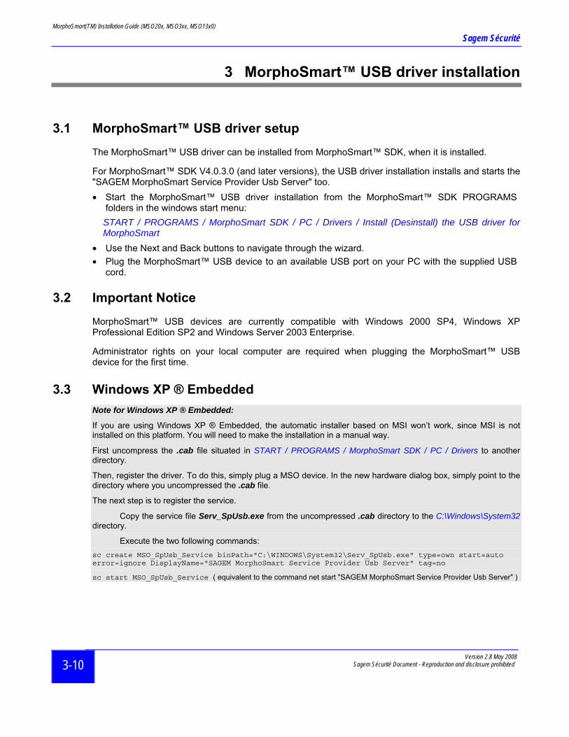
Execute the two following commands: sc create MSO_SpUsb_Service binPath="C:\WINDOWS\System32\Serv_SpUsb.exe" type=own start=auto error=ignore DisplayName="SAGEM MorphoSmart Service Provider Usb Server" tag=no
sc start MSO_SpUsb_Service ( equivalent to the command net start "SAGEM MorphoSmart Service Provider Usb Server" )
MorphoSmart(TM) Installation Guide (MSO20x, MSO3xx, MSO13x0)
Sagem Sécurité
Version 2.8 May 2008 Sagem Sécurité Document - Reproduction and disclosure prohibited 4-11
4 Finger Placement Rules
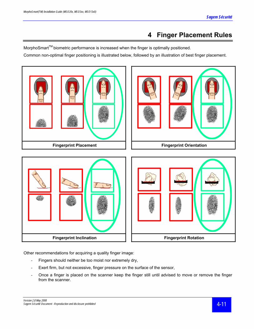
MorphoSmartTM biometric performance is increased when the finger is optimally positioned.
Common non-optimal finger positioning is illustrated below, followed by an illustration of best finger placement.
Fingerprint Placement Fingerprint Orientation
Fingerprint Inclination Fingerprint Rotation
Other recommendations for acquiring a quality finger image:
- Fingers should neither be too moist nor extremely dry,
- Exert firm, but not excessive, finger pressure on the surface of the sensor,
- Once a finger is placed on the scanner keep the finger still until advised to move or remove the finger from the scanner.

MorphoSmart(TM) Installation Guide (MSO20x, MSO3xx, MSO13x0)
Sagem Sécurité
5 MorphoSmartTM MSO20x
5.1 Physical Characteristics
The MSO20x is dedicated to be connected to a RS232 port, and to an external power supply.
Figure 1 : MorphoSmart™ MSO20x 3D view
5.2 Safety instructions
Before plugging your MSO20x into a power source, check that the power source to which you intend to connect it, complies with the voltage, current and frequency specifications on the rating label of the power supply unit (depending on model).
Only use the power supply unit provided with your MorphoSmart™. Do not use any other power supply.
The device does not have an on/off switch and can only be powered off and on by unplugging and plugging the power source. For this reason the device should be connected to an outlet that is easily accessible. The power outlet must be located within a maximum of 8 feet of the terminal.
Version 2.8 May 2008 Sagem Sécurité Document - Reproduction and disclosure prohibited
5-12
MorphoSmart(TM) Installation Guide (MSO20x, MSO3xx, MSO13x0)
Sagem Sécurité
Version 2.8 May 2008 Sagem Sécurité Document - Reproduction and disclosure prohibited 5-13
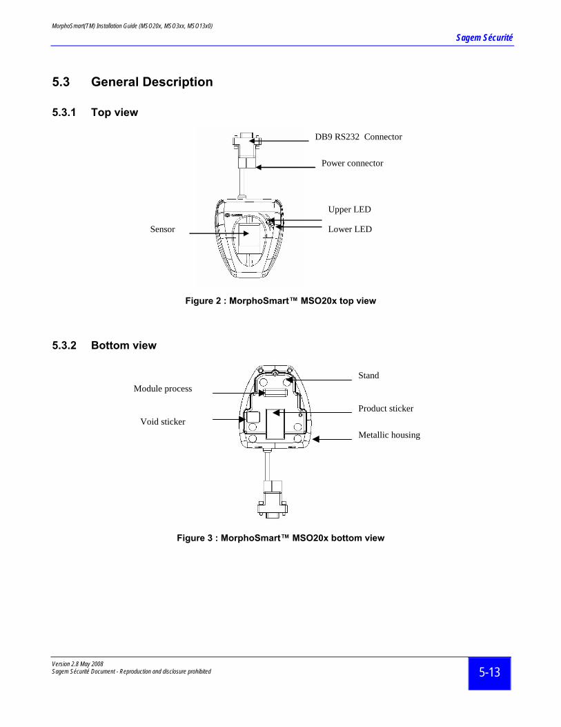
5.3 General Description
5.3.1 Top view
DB9 RS232 Connector
Sensor
Upper LED
Lower LED
Power connector
Figure 2 : MorphoSmart™ MSO20x top view
5.3.2 Bottom view
Stand
Product sticker
Module process
Metallic housingVoid sticker
Figure 3 : MorphoSmart™ MSO20x bottom view
MorphoSmart(TM) Installation Guide (MSO20x, MSO3xx, MSO13x0)
Sagem Sécurité
6 MorphoSmartTM MSO3xx
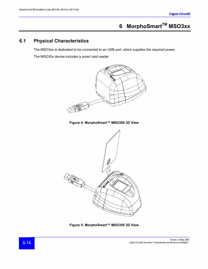
6.1 Physical Characteristics
The MSO3xx is dedicated to be connected to an USB port, which supplies the required power.
The MSO35x device includes a smart card reader
Figure 4: MorphoSmart™ MSO300 3D View
Figure 5: MorphoSmart™ MSO350 3D View
Version 2.8 May 2008 Sagem Sécurité Document - Reproduction and disclosure prohibited
6-14
MorphoSmart(TM) Installation Guide (MSO20x, MSO3xx, MSO13x0)
Sagem Sécurité
Version 2.8 May 2008 Sagem Sécurité Document - Reproduction and disclosure prohibited 6-15
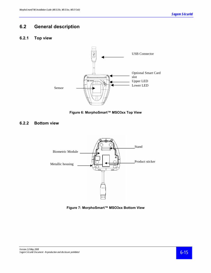
6.2 General description
6.2.1 Top view
USB Connector
Sensor
Upper LED Lower LED
Optional Smart Card slot
Figure 6: MorphoSmart™ MSO3xx Top View
6.2.2 Bottom view
Stand
Product sticker
Biometric Module
Metallic housing
Figure 7: MorphoSmart™ MSO3xx Bottom View
MorphoSmart(TM) Installation Guide (MSO20x, MSO3xx, MSO13x0)
Sagem Sécurité
Version 2.8 May 2008 Sagem Sécurité Document - Reproduction and disclosure prohibited
7-16
7 MorphoSmartTM MSOxx1 : Fake Finger Detection
7.1 MorphoSmartTM MSOxx1 devices
The MorphoSmartTM terminals of the MSO xx1 series have security enhanced features. These terminals integrate a specific mechanism (Sagem Sécurité patents) enabling the device to detect fake fingers, such as paper copied ones.
The following terminals include this mechanism : • MSO201 • MSO301 • MSO351
7.2 Specific recommendations
We advise persons with pacemaker or other electronic disposals against using this MSO xx1 version of the MorphoSmartTM terminal.
7.3 Cleaning Precautions
It is recommended to clean the sensor when it is dirty. Dust lowers the MSO xx1 performances. The cleaning material for sensor must be a soft material to prevent scratches. It is advised to clean the sensor after 1000 uses, with a lightly damp rag, to dry it and to wait a few minutes before starting up again the terminal.
In order to eliminate organic marks, a weekly cleaning is required. In this case, using a rag moistened with diluted dishwashing liquid is advised.
Scratch materials, alcohol and acids products are forbidden.
MorphoSmart(TM) Installation Guide (MSO20x, MSO3xx, MSO13x0)
Sagem Sécurité
Version 2.8 May 2008 Sagem Sécurité Document - Reproduction and disclosure prohibited
8 MorphoSmartTM MSO1300
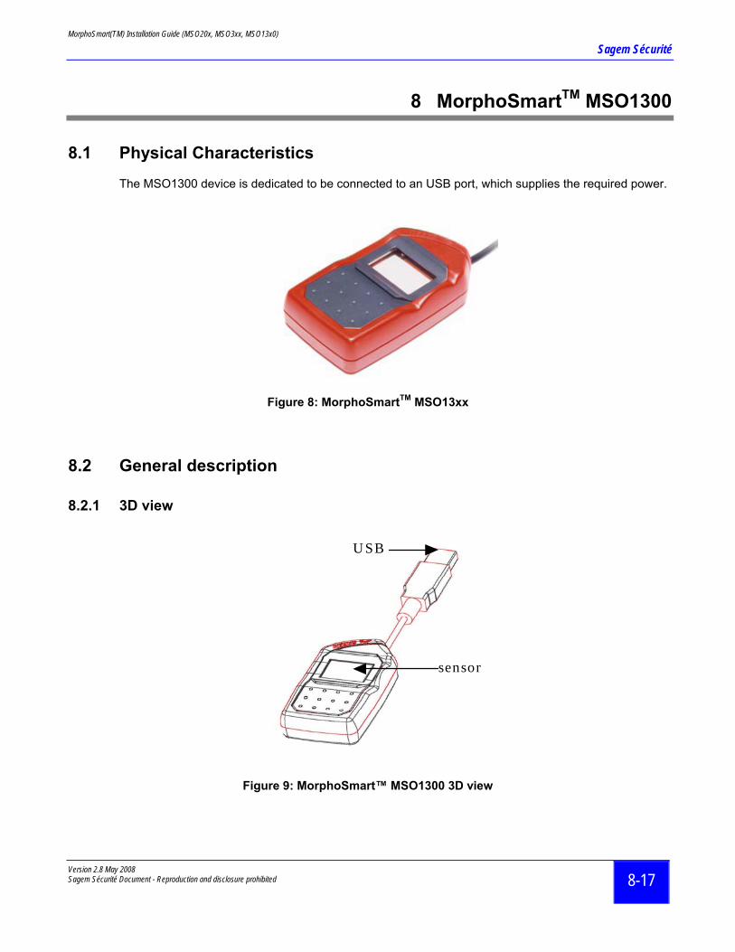
8.1 Physical Characteristics
The MSO1300 device is dedicated to be connected to an USB port, which supplies the required power.
Figure 8: MorphoSmartTM MSO13xx
8.2 General description
8.2.1 3D view
sensor
U SB
Figure 9: MorphoSmart™ MSO1300 3D vie
8-17
w
MorphoSmart(TM) Installation Guide (MSO20x, MSO3xx, MSO13x0)
Sagem Sécurité
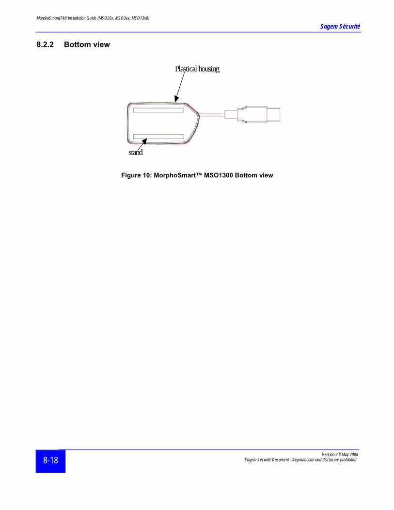
8.2.2 Bottom view
stand
Plastical housing
Figure 10: MorphoSmart™ MSO1300 Bottom view
Version 2.8 May 2008 Sagem Sécurité Document - Reproduction and disclosure prohibited
8-18
MorphoSmart(TM) Installation Guide (MSO20x, MSO3xx, MSO13x0)
Sagem Sécurité
Version 2.8 May 2008 Sagem Sécurité Document - Reproduction and disclosure prohibited 9-19
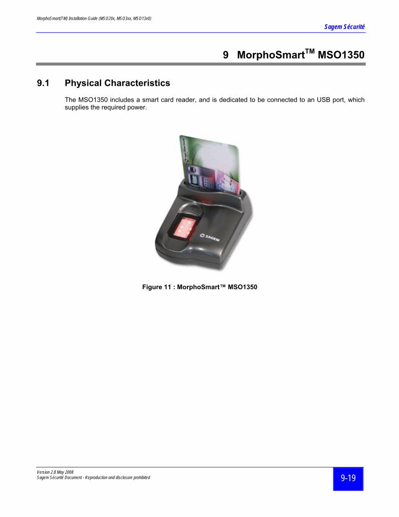
9 MorphoSmartTM MSO1350
9.1 Physical Characteristics
The MSO1350 includes a smart card reader, and is dedicated to be connected to an USB port, which supplies the required power.
Figure 11 : MorphoSmart™ MSO1350
MorphoSmart(TM) Installation Guide (MSO20x, MSO3xx, MSO13x0)
Sagem Sécurité
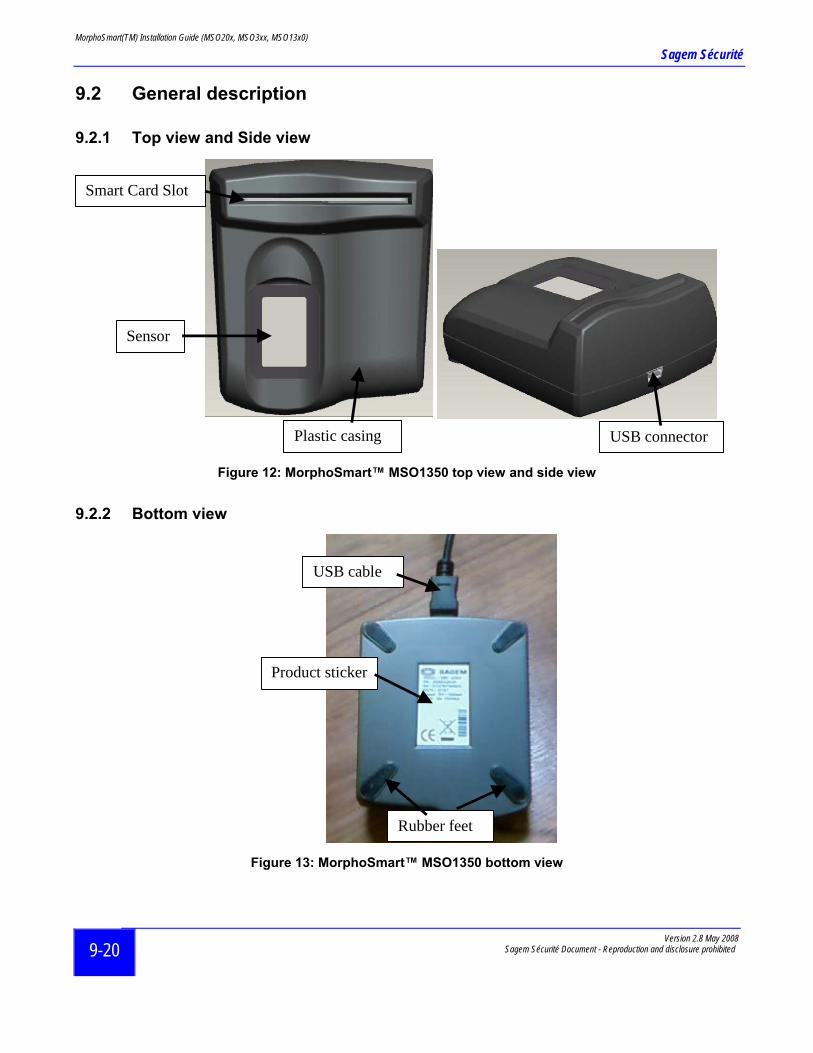
9.2 General description
9.2.1 Top view and Side view
Smart Card Slot
Sensor
Plastic casing
USB connector
Figure 12: MorphoSmart™ MSO1350 top view and side view
9.2.2 Bottom view
USB cable
Product sticker
Rubber feet
Figure 13: MorphoSmart™ MSO1350 bottom view
Version 2.8 May 2008 Sagem Sécurité Document - Reproduction and disclosure prohibited
9-20
MorphoSmart(TM) Installation Guide (MSO20x, MSO3xx, MSO13x0)
Sagem Sécurité
Version 2.8 May 2008 Sagem Sécurité Document - Reproduction and disclosure prohibited 10-21
10 MorphoSmartTM device Technical Characteristics
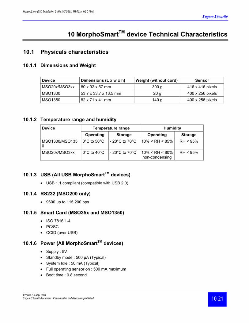
10.1 Physicals characteristics
10.1.1 Dimensions and Weight
Device Dimensions (L x w x h) Weight (without cord) Sensor MSO20x/MSO3xx 80 x 92 x 57 mm 300 g 416 x 416 pixels MSO1300 53.7 x 33.7 x 13.5 mm 20 g 400 x 256 pixels MSO1350 82 x 71 x 41 mm 140 g 400 x 256 pixels
10.1.2 Temperature range and humidity Temperature range Humidity Device
Operating Storage Operating Storage MSO1300/MSO1350
0°C to 50°C - 20°C to 70°C 10% < RH < 85% RH < 95%
MSO20x/MSO3xx 0°C to 40°C - 20°C to 70°C 10% < RH < 80% non-condensing
RH < 95%
10.1.3 USB (All USB MorphoSmartTM devices) • USB 1.1 compliant (compatible with USB 2.0)
10.1.4 RS232 (MSO200 only) • 9600 up to 115 200 bps
10.1.5 Smart Card (MSO35x and MSO1350) • ISO 7816 1-4 • PC/SC • CCID (over USB)
10.1.6 Power (All MorphoSmartTM devices) • Supply : 5V • Standby mode : 500 µA (Typical) • System Idle : 50 mA (Typical) • Full operating sensor on : 500 mA maximum • Boot time : 0.8 second
MorphoSmart(TM) Installation Guide (MSO20x, MSO3xx, MSO13x0)
Sagem Sécurité
Version 2.8 May 2008 Sagem Sécurité Document - Reproduction and disclosure prohibited
10-22
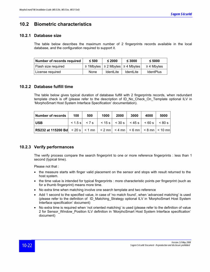
10.2 Biometric characteristics
10.2.1 Database size
The table below describes the maximum number of 2 fingerprints records available in the local database, and the configuration required to support it.
Number of records required ≤ 500 ≤ 2000 ≤ 3000 ≤ 5000 Flash size required ≥ 1Mbytes ≥ 2 Mbytes ≥ 4 Mbytes ≥ 4 Mbytes License required None IdentLite IdentLite IdentPlus
10.2.2 Database fulfill time
The table below gives typical duration of database fulfill with 2 fingerprints records, when redundant template check is off (please refer to the description of ID_No_Check_On_Template optional ILV in ‘MorphoSmart Host System Interface Specification’ documentation).
Number of records 100 500 1000 2000 3000 4000 5000
USB < 1.5 s < 7 s < 15 s < 30 s < 45 s < 60 s < 80 s
RS232 at 115200 Bd < 20 s < 1 mn < 2 mn < 4 mn < 6 mn < 8 mn < 10 mn
10.2.3 Verify performances
The verify process compare the search fingerprint to one or more reference fingerprints : less than 1 second (typical time).
Please not that : • the measure starts with finger valid placement on the sensor and stops with result returned to the
host system. • the time value is intended for typical fingerprints : more characteristic points per fingerprint (such as
for a thumb fingerprint) means more time. • No extra time when matching involve one search template and two reference • Add 1 second to the specified value, in case of ‘no match found’, when ‘advanced matching’ is used
(please refer to the definition of ID_Matching_Strategy optional ILV in ‘MorphoSmart Host System Interface specification’ document)
• No extra time is required when ‘not oriented matching’ is used (please refer to the definition of value 2 for Sensor_Window_Position ILV definition in ‘MorphoSmart Host System Interface specification’ document)
MorphoSmart(TM) Installation Guide (MSO20x, MSO3xx, MSO13x0)
Sagem Sécurité
Version 2.8 May 2008 Sagem Sécurité Document - Reproduction and disclosure prohibited 10-23
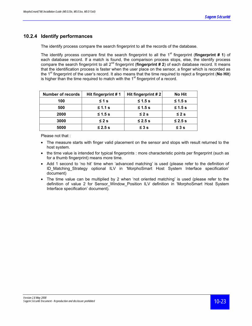
10.2.4 Identify performances
The identify process compare the search fingerprint to all the records of the database.
The identify process compare first the search fingerprint to all the 1st fingerprint (fingerprint # 1) of each database record. If a match is found, the comparison process stops, else, the identify process compare the search fingerprint to all 2nd fingerprint (fingerprint # 2) of each database record. It means that the identification process is faster when the user place on the sensor, a finger which is recorded as the 1st fingerprint of the user’s record. It also means that the time required to reject a fingerprint (No Hit) is higher than the time required to match with the 1st fingerprint of a record.
Number of records Hit fingerprint # 1 Hit fingerprint # 2 No Hit 100 ≤ 1 s ≤ 1.5 s ≤ 1.5 s 500 ≤ 1.1 s ≤ 1.5 s ≤ 1.5 s 2000 ≤ 1.5 s ≤ 2 s ≤ 2 s 3000 ≤ 2 s ≤ 2.5 s ≤ 2.5 s 5000 ≤ 2.5 s ≤ 3 s ≤ 3 s
Please not that : • The measure starts with finger valid placement on the sensor and stops with result returned to the
host system. • the time value is intended for typical fingerprints : more characteristic points per fingerprint (such as
for a thumb fingerprint) means more time. • Add 1 second to ‘no hit’ time when ‘advanced matching’ is used (please refer to the definition of
ID_Matching_Strategy optional ILV in ‘MorphoSmart Host System Interface specification’ document)
• The time value can be multiplied by 2 when ‘not oriented matching’ is used (please refer to the definition of value 2 for Sensor_Window_Position ILV definition in ‘MorphoSmart Host System Interface specification’ document).
MorphoSmart(TM) Installation Guide (MSO20x, MSO3xx, MSO13x0)
Sagem Sécurité
Version 2.8 May 2008 Sagem Sécurité Document - Reproduction and disclosure prohibited
11-24
11 Man Machine Interface
11.1 MSO2xx/MSO3xx Man Machine Interface
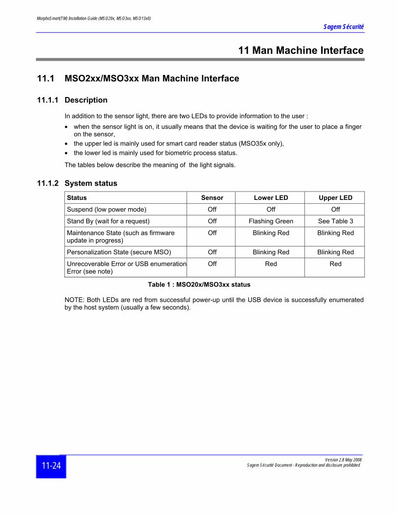
11.1.1 Description
In addition to the sensor light, there are two LEDs to provide information to the user : • when the sensor light is on, it usually means that the device is waiting for the user to place a finger
on the sensor, • the upper led is mainly used for smart card reader status (MSO35x only), • the lower led is mainly used for biometric process status.
The tables below describe the meaning of the light signals.
11.1.2 System status
Status Sensor Lower LED Upper LED
Suspend (low power mode) Off Off Off
Stand By (wait for a request) Off Flashing Green See Table 3
Maintenance State (such as firmware update in progress)
Off Blinking Red Blinking Red
Personalization State (secure MSO) Off Blinking Red Blinking Red
Unrecoverable Error or USB enumeration Error (see note)
Off Red Red
Table 1 : MSO20x/MSO3xx status
NOTE: Both LEDs are red from successful power-up until the USB device is successfully enumerated by the host system (usually a few seconds).
MorphoSmart(TM) Installation Guide (MSO20x, MSO3xx, MSO13x0)
Sagem Sécurité
Version 2.8 May 2008 Sagem Sécurité Document - Reproduction and disclosure prohibited 11-25
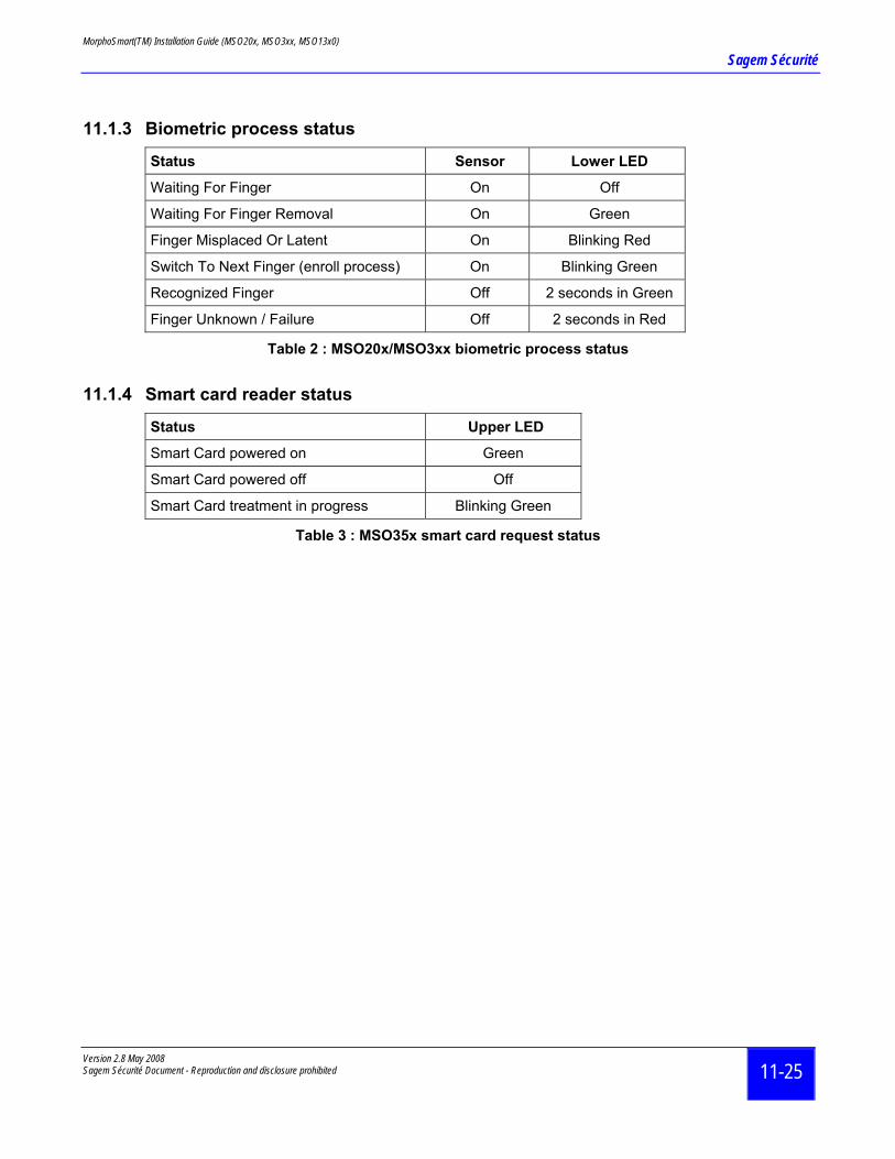
11.1.3 Biometric process status
Status Sensor Lower LED
Waiting For Finger On Off
Waiting For Finger Removal On Green
Finger Misplaced Or Latent On Blinking Red
Switch To Next Finger (enroll process) On Blinking Green
Recognized Finger Off 2 seconds in Green
Finger Unknown / Failure Off 2 seconds in Red
Table 2 : MSO20x/MSO3xx biometric process status
11.1.4 Smart card reader status
Status Upper LED
Smart Card powered on Green
Smart Card powered off Off
Smart Card treatment in progress Blinking Green
Table 3 : MSO35x smart card request status
MorphoSmart(TM) Installation Guide (MSO20x, MSO3xx, MSO13x0)
Sagem Sécurité
Version 2.8 May 2008 Sagem Sécurité Document - Reproduction and disclosure prohibited
11-26
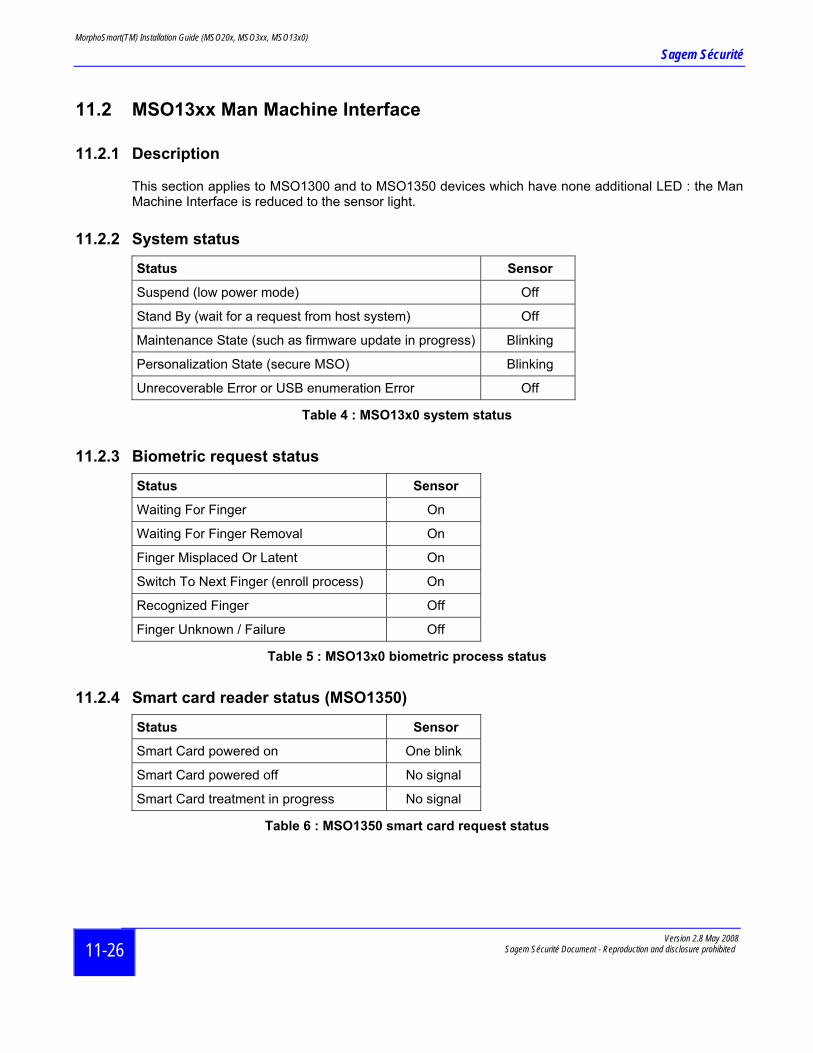
11.2 MSO13xx Man Machine Interface
11.2.1 Description
This section applies to MSO1300 and to MSO1350 devices which have none additional LED : the Man Machine Interface is reduced to the sensor light.
11.2.2 System status
Status Sensor
Suspend (low power mode) Off
Stand By (wait for a request from host system) Off
Maintenance State (such as firmware update in progress) Blinking
Personalization State (secure MSO) Blinking
Unrecoverable Error or USB enumeration Error Off
Table 4 : MSO13x0 system status
11.2.3 Biometric request status
Status Sensor
Waiting For Finger On
Waiting For Finger Removal On
Finger Misplaced Or Latent On
Switch To Next Finger (enroll process) On
Recognized Finger Off
Finger Unknown / Failure Off
Table 5 : MSO13x0 biometric process status
11.2.4 Smart card reader status (MSO1350)
Status Sensor
Smart Card powered on One blink
Smart Card powered off No signal
Smart Card treatment in progress No signal
Table 6 : MSO1350 smart card request status

MorphoSmart(TM) Installation Guide (MSO20x, MSO3xx, MSO13x0)
Sagem Sécurité
Version 2.8 May 2008 Sagem Sécurité Document - Rep
12 Secure MorphoSmart™ getting started
In addition to normal installation process, the secure MORPHOSMART™ device must be unlocked and personalized. To perform this, the security information provided with the batch of secure MORPHOSMART™ devices are required: two transport files (usually send by email), and their corresponding password (usually send under secure cover).
g
MORPHOSMART™ Key Management System
(MKMS)
MSO n
MSO i
MSO 1Transp File1
Key2
Key1 +
Transp File2
+
Insert the MKMS Croot directory of the
After installation, st
START / P
After installation, st
START / P
Select the 'Root Certification Author
Click ‘Insert Trandatabase (figure 1)
Set up the value of
Then connect a neit, and to put it in op
Perform the previo
For more infoMorphoSmartKey
START / P
Figure 1: MORPHOSMART™ S unlockin
roduction and disclosure prohibited 12-27
D into your CDROM drive. If installation does not start automatically, run setup.exe from the CD.
art the DAO 3.6 driver installation from the PROGRAMS folders:
ROGRAMS / MorphoSmartKeyManagementSystem / InstallDAO 3.6 /.
art the MKMS application from the PROGRAMS folders:
ROGRAMS / MorphoSmartKeyManagementSystem / Exe /
key generation' action in the 'Initialization' menu, to create your MORPHOSMART™ ity.
sport Files’ button to import the two transport files and their passwords into the MKMS .
the security configuration parameters and of the key parameters ('Initialization' menu).
w MORPHOSMART™ device to the PC, and use the 'MSO Personalization' button to unlock erational condition.
us action for each new secure MORPHOSMART™ device of the batch.
rmation about the secure MORPHOSMART™ , please refer to the ManagementSystem.pdf file from the PROGRAMS folders:
ROGRAMS / MORPHOSMART™KeyManagementSystem /Documentation /
MorphoSmart(TM) Installation Guide (MSO20x, MSO3xx, MSO13x0)
Sagem Sécurité
Version 2.8 May 2008 Sagem Sécurité Document - Reproduction and disclosure prohibited
13-28
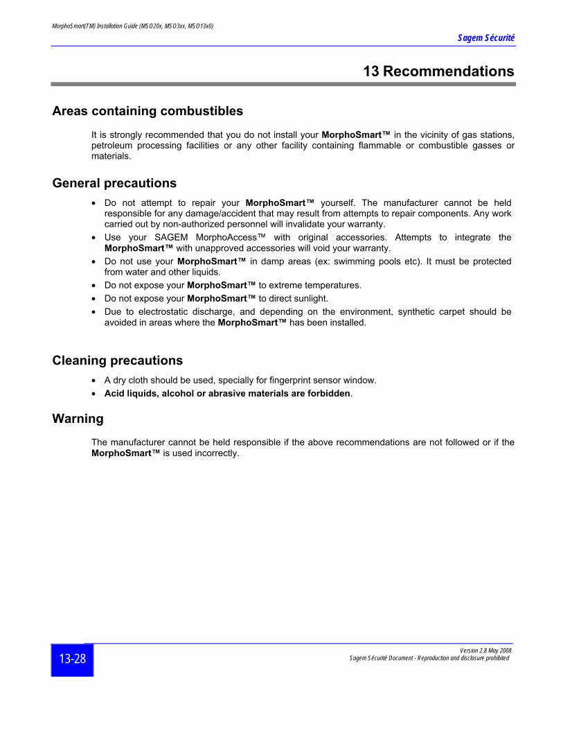
13 Recommendations
Areas containing combustibles
It is strongly recommended that you do not install your MorphoSmart™ in the vicinity of gas stations, petroleum processing facilities or any other facility containing flammable or combustible gasses or materials.
General precautions • Do not attempt to repair your MorphoSmart™ yourself. The manufacturer cannot be held
responsible for any damage/accident that may result from attempts to repair components. Any work carried out by non-authorized personnel will invalidate your warranty.
• Use your SAGEM MorphoAccess™ with original accessories. Attempts to integrate the MorphoSmart™ with unapproved accessories will void your warranty.
• Do not use your MorphoSmart™ in damp areas (ex: swimming pools etc). It must be protected from water and other liquids.
• Do not expose your MorphoSmart™ to extreme temperatures. • Do not expose your MorphoSmart™ to direct sunlight. • Due to electrostatic discharge, and depending on the environment, synthetic carpet should be
avoided in areas where the MorphoSmart™ has been installed.
Cleaning precautions
• A dry cloth should be used, specially for fingerprint sensor window. • Acid liquids, alcohol or abrasive materials are forbidden.
Warning
The manufacturer cannot be held responsible if the above recommendations are not followed or if the MorphoSmart™ is used incorrectly.
MorphoSmart(TM) Installation Guide (MSO20x, MSO3xx, MSO13x0)
Sagem Sécurité
Version 2.8 May 2008 Sagem Sécurité Document - Reproduction and disclosure prohibited 14-29
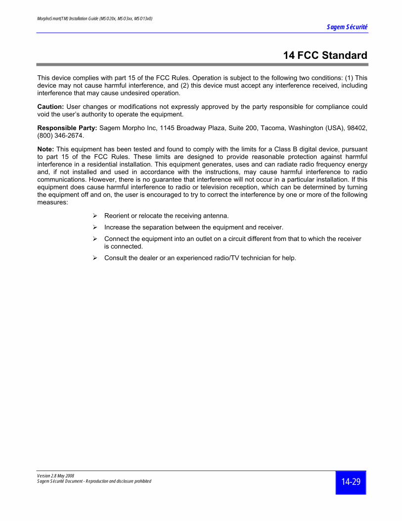
14 FCC Standard
This device complies with part 15 of the FCC Rules. Operation is subject to the following two conditions: (1) This device may not cause harmful interference, and (2) this device must accept any interference received, including interference that may cause undesired operation.
Caution: User changes or modifications not expressly approved by the party responsible for compliance could void the user’s authority to operate the equipment.
Responsible Party: Sagem Morpho Inc, 1145 Broadway Plaza, Suite 200, Tacoma, Washington (USA), 98402, (800) 346-2674.
Note: This equipment has been tested and found to comply with the limits for a Class B digital device, pursuant to part 15 of the FCC Rules. These limits are designed to provide reasonable protection against harmful interference in a residential installation. This equipment generates, uses and can radiate radio frequency energy and, if not installed and used in accordance with the instructions, may cause harmful interference to radio communications. However, there is no guarantee that interference will not occur in a particular installation. If this equipment does cause harmful interference to radio or television reception, which can be determined by turning the equipment off and on, the user is encouraged to try to correct the interference by one or more of the following measures:
Reorient or relocate the receiving antenna.
Increase the separation between the equipment and receiver.
Connect the equipment into an outlet on a circuit different from that to which the receiver is connected.
Consult the dealer or an experienced radio/TV technician for help.
MorphoSmart(TM) Installation Guide (MSO20x, MSO3xx, MSO13x0)
Sagem Sécurité
Version 2.8 May 2008 Sagem Sécurité Document - Reproduction and disclosure prohibited
15-30
15 Table of figures
Figure 1 : MorphoSmart™ MSO20x 3D view .................................................................................................................. 5-12 Figure 2 : MorphoSmart™ MSO20x top view.................................................................................................................. 5-13 Figure 3 : MorphoSmart™ MSO20x bottom view............................................................................................................ 5-13 Figure 4: MorphoSmart™ MSO300 3D View .................................................................................................................. 6-14 Figure 5: MorphoSmart™ MSO350 3D View .................................................................................................................. 6-14 Figure 6: MorphoSmart™ MSO3xx Top View................................................................................................................. 6-15 Figure 7: MorphoSmart™ MSO3xx Bottom View ........................................................................................................... 6-15 Figure 8: MorphoSmartTM MSO13xx................................................................................................................................ 8-17 Figure 9: MorphoSmart™ MSO1300 3D view ................................................................................................................. 8-17 Figure 10: MorphoSmart™ MSO1300 Bottom view ........................................................................................................ 8-18 Figure 11 : MorphoSmart™ MSO1350............................................................................................................................. 9-19 Figure 12: MorphoSmart™ MSO1350 top view and side view........................................................................................ 9-20 Figure 13: MorphoSmart™ MSO1350 bottom view......................................................................................................... 9-20