Embed Size (px)
Citation preview

MorphoAccessTM
Installation Guide MA500 Series
Produced by Sagem Sécurité Copyright ©2007 Sagem Sécurité
www.sagem-securite.com
MorphoAccessTM Installation guide OMA520/521 and MA500/520/521
July 2007SK 0000053018-03


2 SAGEM Sécurité document. Reproduction and disclosure forbidden. SK-53018-03

CONTENTS
INTRODUCTION 5
SAFETY INSTRUCTIONS 6
EUROPE INFORMATION : 6 USA INFORMATION 7 CANADIAN INFORMATION 7
GENERAL DESCRIPTION 8
MA5XX VERSIONS INSTALLATION PROCEDURE 10
STAGE 1: DRILLING THE MOUNTING HOLES 10 STAGE 2: MOUNTING THE METAL CHASSIS ASSEMBLY 11 STAGE 3: CONNECTING THE CHASSIS ASSEMBLY TO THE COVER ASSEMBLY 12 STAGE 4: CLOSING MORPHOACCESS™ 13
OMA5XX VERSIONS INSTALLATION PROCEDURE 14
STAGE 1: DRILLING THE MOUNTING HOLES 14 STAGE 2 : OMA5XX FIXING 15 STAGE 3 : OMA5XX CABLING 15 STAGE 4 : CLOSING OMA5XX 15
ELECTRICAL INTERFACE 16
MA5XX TERMINAL BLOCK BOARD WIRING 16 OMA5XX REAR VIEW AND CABLES 17 POWER SUPPLY SOURCE 18 WIEGAND OUTPUT WIRING 19 DATA CLOCK OUTPUT WIRING 19 WIEGAND INPUT WIRING 20 DATA CLOCK INPUT WIRING 20 COM RS422 SERIAL PORT 21 COM RS485 SERIAL PORT 21 ETHERNET WIRING 22 OUTPUT RELAY AND SECURITY SWITCHES 23
USER INTERFACE 25
SK-53018-03 SAGEM Sécurité document. Reproduction and disclosure forbidden. 3

MORPHOACCESSTM MA5XX SERIES TECHNICAL CHARACTERISTICS 26
MAN MACHINE INTERFACE 26 BIOMETRY 26 PERIPHERALS INTERFACES 26 POWER SUPPLY 27 SIZE AND WEIGHT 27 ENVIRONNEMENTAL CONDITIONS 28
RECOMMENDATIONS 29
AREAS CONTAINING COMBUSTIBLES 29 GENERAL PRECAUTIONS 29 SPECIFIC PRECAUTIONS FOR RADIO TERMINALS 29 ETHERNET CONNECTION 30 DATE / TIME SYNCHRONIZATION 30 CLEANING PRECAUTIONS 30 WARNING 30 BIOMETRICS TERMINALS HOT LINE 30
APPENDIX 1 - FINGERPRINT PLACEMENT RULES 31
APPENDIX 2 – RELATED DOCUMENTS 32
APPENDIX 3 - DRILLING TEMPLATE 34
MA5XX VERSIONS 34 OMA5XX VERSIONS 35
SUPPORT 36
CUSTOMER SERVICE 36 HOTLINE 36
4 SAGEM Sécurité document. Reproduction and disclosure forbidden. SK-53018-03
IINNTTRROODDUUCCTTIIOONN
Congratulations for choosing the SAGEM MorphoAccess™1 Automatic Fingerprint Recognition Terminal. MorphoAccess™ provides an innovative and effective solution for access control applications using Fingerprint Verification or/ and Identification. Among a range of alternative biometric techniques, the use of finger imaging has significant advantages: each finger constitutes an unalterable physical signature which develops before birth and is preserved until death. Unlike DNA, a finger image is unique to each individual - even identical twins. The MorphoAccess™ terminal integrates SAGEM image processing and feature matching algorithms (MorphoSoft™ and MorphoImaging™). This technology is based on lessons learned during more than 20 years of experience in the field of biometric identification and the creation of literally millions of individual fingerprint identification records. We believe you will find the SAGEM MorphoAccess™ fast, accurate, easy to use and suitable for physical access control. The SAGEM MorphoAccess™ offers the following advantages:
• High quality optical sensor ( IQS certified )
• Supports multiple input/output interfaces used in the physical access control industry.
• Local area network interface for easy interaction with other host systems.
• Compact size for easy installation and integration into your available office space.
• Intuitive man machine interface with keyboard and display, that is easy to use in both setup and operational modes.
• Open architecture, with dedicated applications implemented via MA5xx/1xx Software Development Kit.
To ensure the most effective use of your SAGEM MorphoAccess™, we recommend that you read this Installation Guide thoroughly.
1 The SAGEM logo and trademark are the property of SAGEM Sécurité.
All other trademarks or product names are trademarks or product names of the respective title holders.
SK-53018-03 SAGEM Sécurité document. Reproduction and disclosure forbidden. 5

SSAAFFEETTYY IINNSSTTRRUUCCTTIIOONNSS
The installation of this product should be made by a qualified service technician and should conform to all local codes. It is strongly recommended that a class II power supply at 12 V ±5% and 0.75 A. min be used in accordance with Safety Electrical Low Voltage (SELV) parameters. The 12 V power supply cable length should not exceed 5 meters. This product may be installed with a power supply conforming to EN60950, in accordance with the NEC Class 2 requirements; or supplied by a listed EN60950 external Power Unit marked Class 2, Limited Power source, or LPS and rated 12 V DC, 0.75 A minimum. In case of “Power Over Ethernet” use, the POE hub or switch features has to be conformed with IEEE 802.3-af standard. An insulation greater than 2000V is provided between MA5xx terminal and Ethernet network. In case of building to building connection it is recommended to connect 0V to ground. This ground (ground security reference) cable must be connected with the terminal block board fixation screw marked with the universal ground symbol ( see p16 ).
EEuurrooppee iinnffoorrmmaattiioonn ::
SAGEM hereby declares that the SAGEM MorphoAccess™ has been tested and found compliant with the following listed standards as required by the EMC Directive 89/336/EEC: EN55022 (1994) / EN55024 (1998), EN300-330 (1999) and by the low voltage Directive 73/23/EEC amended by 93/68/EEC: EN60950 (2000). Caution: The MA500 terminal is a Class A device. In a residential environment, this device may cause interference. In this case, the user is encouraged to try to correct the interference with appropriated measures such as :
• Reorient or relocate the receiving antenna.
• Increase the separation between the equipment and receiver.
• Connect the equipment into an outlet on a circuit different from that to which the receiver is connected.
• Consult the dealer or an experienced radio/TV technician for help.
6 SAGEM Sécurité document. Reproduction and disclosure forbidden. SK-53018-03

UUSSAA iinnffoorrmmaattiioonn
Caution: FCC part 15 certificates are pending.
This device complies with part 15 of the FCC Rules. Operation is subject to the following two conditions: (1) This device may not cause harmful interference, and (2) this device must accept any interference received, including interference that may cause undesired operation. Changes or modifications not expressly approved by the party responsible for compliance could void the user’s authority to operate the equipment.
Responsible Party : Sagem Morpho Inc, 1145 Broadway Plaza, Suite 200, Tacoma, Washington (USA), 98402, (800) 346-2674.
Note : This equipment has been tested and found to comply with the limits for a Class B (MA520, MA521, OMA520, OMA521) or Class A (MA500) digital device, pursuant to part 15 of the FCC Rules. These limits are designed to provide reasonable protection against harmful interference in a residential installation. This equipment generates, uses and can radiate radio frequency energy and, if not installed and used in accordance with the instructions, may cause harmful interference to radio communications. However, there is no guarantee that interference will not occur in a particular installation. If this equipment does cause harmful interference to radio or television reception, which can be determined by turning the equipment off and on, the user is encouraged to try to correct the interference by one or more of the following measures:
• Reorient or relocate the receiving antenna.
• Increase the separation between the equipment and receiver.
• Connect the equipment into an outlet on a circuit different from that to which the receiver is connected.
• Consult the dealer or an experienced radio/TV technician for help.
CCaannaaddiiaann iinnffoorrmmaattiioonn
Caution: Industrial Canadian certificates are pending. This Class B (MA520, MA521, OMA520, OMA521) or Class A (MA500) digital apparatus complies with Canadian ICES-003. Ces appareils numériques de Classe B (MA520, MA521, OMA520, OMA521) ou Classe A (MA500) sont conformes à la norme NMB-003 du Canada.
SK-53018-03 SAGEM Sécurité document. Reproduction and disclosure forbidden. 7

GGEENNEERRAALL DDEESSCCRRIIPPTTIIOONN
MA5xx versions
Display
128 x 64 dots
Function keys
Keyboard Ca
( MA520 / 5
Mounting keyholes
Cable entry
MorphoAccess™ supplies:
1 Cover assembly with Chassis and 2 Secured screws for fixa1 Secured screwdriver Torx 20 1 Chassis fixation kit ( 4 fixations and screws , 1 anti theft bloc
8 SAGEM Sécurité document. Reproduction and disclosure forbidden.
MIFARE
rd reader
21 only )
tio
k
Sensor
Anti-theft
entry
Metal chassis
n
)
SK-53018-03

OMA5xx versions
Display
128 x 64 dots
Function keys
Keyboard
Ca
( MA520 / 5
Protective visor
4 Mounting slots
Outdoor MorphoAccess™ supplies: 1 Cover assembly with chassis and protective visor 1 Secured screwdriver Torx 10 1 Chassis fixation kit ( 4 fixations and screws )
SK-53018-03 SAGEM Sécurité document. Reproduction and disclosure forbidden.
MIFARE
rd reader
21 only )
Sensor
9

MMAA55XXXX VVEERRSSIIOONNSS IINNSSTTAALLLLAATTIIOONN PPRROOCCEEDDUURREE
SSttaaggee 11:: DDrriilllliinngg tthhee mmoouunnttiinngg hhoolleess
Mounting and cable entry hole location (rear view)
10 SAGEM Sécurité document. Reproduction and disclosure forbidden. SK-53018-03
a) Using the dimensional drawing in Appendix 3, drill 2 holes for the mounting keyholes screws so that the cable entry is in a suitable position for cabling. b) Drill the hole for the third screw in the center of the slot so that it is possible to correct the position later, if necessary. c) The mounting screws must be 5 mm diameter maximum.

SSttaaggee 22:: MMoouunnttiinngg tthhee mmeettaall cchhaassssiiss aasssseemmbbllyy
a) Disconnect the ribbon cable between the mothblock board so that the assembly shown above crest of MorphoAccess™. b) Pass the connecting cables through the cablec) Position the chassis assembly against the wathe mounting keyholes. d) Hold the chassis in place with a screw throughe) Adjust the position, and fix in place by tightenif) Adjust the anti theft block into the hole design
the last and fourth screw. Check that nothing is interfering with the component ) and the anti theft block.
g) Connect cables to terminal blocks with adequscrew dimensions ( see the detailed instrsections )
Be sure during manipulation that the pelectrical source is off.
SK-53018-03 SAGEM Sécurité document. Reproduction and disclosure f
Terminal block board
Anti theft switch
erboaran be
entry. ll using
the mng all thed for
anti th
ate touctions
ower
orbidden.
Cable entry
Chassis bold receivers
d and the terminal detached from the
the two screws in
ounting slot. ree screws.
it, and fix in place
eft switch ( opto
rque conformed to in the following
supply from the
11

SSttaaggee 33:: CCoonnnneeccttiinngg tthhee cchhaassssiiss aasssseemmbbllyy ttoo tthhee ccoovveerr aasssseemmbbllyy
Ribbon cable connector location
Position of the ribbon cable
12 SAGEM Sécurité document. R
Tamper switch
Motherboard/terminal block boardribbon cable connectorCover assembly
as the case is closed
The ribbon cable shown so th
easily without da
eproduction and disclosure forbidden.
Cover assembly
Chassis assembly
Chassis assembly
must be folded asat the case closesmaging the cable
SK-53018-03

SSttaaggee 44:: CClloossiinngg MMoorrpphhooAAcccceessss™™
SK-53018-03
Catch for the cover assembly lip
Lip
When the ribbon cable has been connected between the two assemblies (see stage 3), the cover assembly is fitted to the chassis assembly.
1 The lip on the cover slides behind the chassis, to fit over the catch shown on the diagram above.
2 The cover is fitted onto the chassis by rotating it.
M
Fit the two M4x16 assembly screws.
Use screwdriver TORX 20
SAGEM Sécurité document. Reproduction and disclosure
Assembled orphoAccessTM
forbidden. 13

OOMMAA55XXXX VVEERRSSIIOONNSS IINNSSTTAALLLLAATTIIOONN PPRROOCCEEDDUURREE
SSttaaggee 11:: DDrriilllliinngg tthhee mmoouunnttiinngg hhoolleess
Mounting hole location (rear view)
a) Using the dimensional drawing for OMA5xx in Appendix 3, drill holes for the four mounting bolts, vertically centered within the four slots.
b) The mounting bolts must be 5 mm diameter maximum.
14 SAGEM Sécurité document. Reproduction and disclosure forbidden. SK-53018-03
SSttaaggee 22 :: OOMMAA55xxxx ffiixxiinngg
a) Remove protective visor ( 4 small caps at each corner ) before fixing OMA5xx assembly. Remove the 4 small caps at each corner of the protective visor , with a small screw driver Remove the 4 screws , with T10 screw driver supplied.
b) Adjust the OMA5xx assembly in front of the 4 holes. c) Fix the 4 mounting bolts ( 2 in upper zone , 2 in lower zone )
SSttaaggee 33 :: OOMMAA55xxxx ccaabblliinngg
a) Connect necessary OMA cables to user wires ( see the detailed instructions in the following sections )
SSttaaggee 44 :: CClloossiinngg OOMMAA55xxxx
a) Mount protective visor with 4 screws and T10 screw driver. b) Put the 4 small caps.
SK-53018-03 SAGEM Sécurité document. Reproduction and disclosure forbidden. 15

EELLEECCTTRRIICCAALL IINNTTEERRFFAACCEE
MMAA55xxxx TTeerrmmiinnaall bblloocckk bbooaarrdd wwiirriinngg
Anti theft opto
y
RS4 5
Te
Power supply source External +12V DC
or Power Over Ethernet
16 SAGEM Sécurité document. Reproduction and d
Wiegand INDataclock IN
isclosure forbidden.
Ethernet rminal block
or RJ45
Wiegand OUTDataclock OUT
COM 22 / RS48
Rela
Tamper switch Anti theft switch
Ground security
reference
SK-53018-03

OOMMAA55xxxx rreeaarr vviieeww aanndd ccaabblleess
Power Supply source
5
5
Ethernet RJ4Wiring ( cables colors and cables positions ) is not exactly tas previous OMA2xx/3xx family.
In order to be complied with EMC directives ( See p 6 ), all cables
from Access Control system must be shielded. Both shield wires ( OMA5xx cable , AC system cable ) must be tied toShield wire from OMA5xx cable is the wire without insulation.
SK-53018-03 SAGEM Sécurité document. Reproduction and disclosure forbidden.
Tamper switch Relay
he
co
get
Wiegand DataClock
COM RS422/ 48
same
ming
her.
17

PPoowweerr SSuuppppllyy ssoouurrccee
MA5xx OMA5xx
Power cable
1 Block 1 +12V In Positive 12 Volts, power supply. Red
2 Block 2 GND/ALIM In Ground power supply. Black
Ground In Ground security reference yellow/green
Power supply: Must conform to CEE/EEC EN60950 standard 9V to 16 Volts ± 5% (regulated) 1,5 Amp max ( peak ) Power may come from a 12 Volts Wiegand power supply, conforming to the Security Industry Association's Wiegand standard March 1995 , able to deliver 9 Watts. In standard operating activity, typical power consumption is 4,5 Watts. In extreme temperature conditions, with all options ( USB key , 12V output for Wiegand in ), maximum power consumption is up to 9 Watts.
MA5xx terminal make use of POE functionality ; If Ethernet network is POE compatible, power supply may come from Ethernet wiring.
For systems placed in other building than supervisor one's, the electrical security is guaranteed with a "ground connection" to the terminal. For a higher susceptibility level, we recommend to the installer to connect a "ground connection" to the terminal.
MA5xx : A cable terminal connected to "ground security reference" must be tied to the fixation designed for ( see p 16 ). OMA5xx : the yellow/green wire in power supply cable must be connected to "ground security reference".
18 SAGEM Sécurité document. Reproduction and disclosure forbidden. SK-53018-03

WWiieeggaanndd oouuttppuutt wwiirriinngg
MA5xx OMA5xx
Wiegand Dataclock cable
1 Block 1 D0 Out Wiegand D0 Green
2 Block 2 D1 Out Wiegand D1 White
3 Block 3 LED1 In Wiegand LED IN 1 (option) Brown
4 Block 4 LED2 In Wiegand LED IN 2 (option) Grey
5 Block 5 GND Ground for Wiegand Black
Electrical interface conforms to the Security Industry Association's Wiegand standard March 1995, and it is 5V TTL compatible.
DDaattaa CClloocckk oouuttppuutt wwiirriinngg
MA5xx OMA5xx
Wiegand Dataclock cable
1 Block 1 D0 Out Data ( 5V TTL ) Green
2 Block 2 D1 Out Clock ( 5V TTL ) White
3 Block 3 LED1 NC NC
4 Block 4 LED2 NC NC
5 Block 5 GND Ground for Dataclock Black
SK-53018-03 SAGEM Sécurité document. Reproduction and disclosure forbidden. 19

WWiieeggaanndd iinnppuutt wwiirriinngg
MA5xx OMA5xx
Wiegand Dataclock cable
1 Block 1 D0 In Wiegand D0 Blue
2 Block 2 D1 In Wiegand D1 Yellow
3 Block 3 LED Out Wiegand LED OUT 1 (option) Orange
4 Block 4 +12V Out 12 Volts Power output (150 mA max) Red
5 Block 5 GND Ground for Wiegand Black
Electrical interface conforms to the Security Industry Association's Wiegand standard March 1995, and it is 5V TTL compatible.
DDaattaa CClloocckk iinnppuutt wwiirriinngg
MA5xx OMA5xx
Wiegand Dataclock cable
1 Block 1 D0 In Data ( 5V TTL ) Blue
2 Block 2 D1 In Clock ( 5V TTL ) Yellow
3 Block 3 LED NC NC
4 Block 4 +12V Out 12 Volts Power output (150 mA max) Red
5 Block 5 GND Ground for Dataclock Black
20 SAGEM Sécurité document. Reproduction and disclosure forbidden. SK-53018-03

CCOOMM RRSS442222 sseerriiaall ppoorrtt
MA5xx OMA5xx
COM RS422/RS485 cable
1 Block 1 GND Ground for RS422 Grey or White
2 Block 2 Tx- Out RS422 Negative Transmit Orange
3 Block 3 Tx+ Out RS422 Positive Transmit Orange/White
4 Block 4 Rx- In RS422 Negative Receive Green
5 Block 5 Rx+ In RS422 Positive Receive Green/White
RS422 interface is a full duplex communication.
CCOOMM RRSS448855 sseerriiaall ppoorrtt
MA5xx OMA5xx
COM RS422/RS485 cable
1 Block 1 GND Ground for RS485 Grey or White
2 Block 2 Tx- Out RS485 Negative Transmit Orange
3 Block 3 Tx+ Out RS485 Positive Transmit Orange/White
4 Block 4
5 Block 5
RS485 implementation is limited to half-duplex communication. So only Tx+ and Tx- and ground reference signals are necessary. Depending on the RS485 network, an impedance adaptation may be required. For farthest terminal, a 120 Ohms resistor termination may be added to the terminal, by strapping block 2 and block 3.
SK-53018-03 SAGEM Sécurité document. Reproduction and disclosure forbidden. 21

EEtthheerrnneett wwiirriinngg
2 ways for Ethernet wiring : - Terminal block connection ( MA5xx only )
MA5xx OMA5xx
Ethernet cable
1 Block 1 RX- In Receive negative Ethernet RJ45 Pin 6
2 Block 2 RX+ In Receive positive Ethernet RJ45 Pin 3
3 Block 3 TX- Out Transmit negative Ethernet RJ45 Pin 2
4 Block 4 TX+ Out Transmit positive Ethernet RJ45 Pin 1
5 Block 5 GND Ground for shield Ethernet RJ45 Pin 7
- RJ 45 cabling connection
RJ45 Pinout Signals EIA/TIA
T568B color EIA/TIA
T568A color Corel L120
color
1 TX(+) Transmit Data Plus White Orange White Green Grey
2 TX(-) Transmit Data Minus Orange Green White
3 RX(+) Receive Data Plus White Green White Orange Pink
4 No connection Blue Blue Orange
5 No connection White blue White blue Yellow
6 RX(-) Receive Data Minus Green Orange Blue
7 Ground protection (option) White Brown White Brown Purple
8 No connection Brown Brown Brown
RJ45 plug pinout is compliant with 10/100 base T, IEEE802.3 Specification. RJ45 plug and Ethernet terminal block connections are compliant with Power Over Ethernet ( POE ) IEEE802.3 af Specification. See details page 27.
22 SAGEM Sécurité document. Reproduction and disclosure forbidden. SK-53018-03
Default IP address from factory setting is : 134.1.32.214

OOuuttppuutt rreellaayy aanndd sseeccuurriittyy sswwiittcchheess
MA5xx OMA5xx
Switch/relay cable
1 Block 1 CRO Contact relay normally open Red
2 Block 2 CRC Contact relay normally closed Orange
3 Block 3 CR Contact relay common Yellow
4 Block 6 TSW2_1 Tamper switch Contact 1 White
5 Block 7 TSW2-0 Tamper switch Contact 0 Green
6 Block 4 ATSW1_1 Anti theft switch Contact 1 Not available
7 Block 5 ATSW1_0 Anti theft switch Contact 0 Not available
Ground Not connected Black (*)
(*) : For this interface connection , it is not recommend to connect black wire to Ground. Various ground reference are not recommended.
This terminal is part of security system. In order to prevent unauthorized access into this terminal it is the customer’s responsibility to connect the tamper switch and the anti theft switch ( MA5xx only ) to the physical access controller (connected mode).
Anti-theft and tamper switchs ratings
2 A at 30 VDC according to the safety extra low voltage requirements (62.5 VAC max, 220 VDC max and 125 VAC max) independently of the power supply.
The tamper function is activated with the proper screw positioning, between cover and chassis.
Terminal closed : Tamper switch ON Terminal open : Tamper switch OFF
The anti theft function is activated by the anti theft block positioning in front of the opto component ( not available with OMA5xx )
Terminal on wall : Anti theft switch ON Terminal out wall : Anti theft switch OFF
SK-53018-03 SAGEM Sécurité document. Reproduction and disclosure forbidden. 23
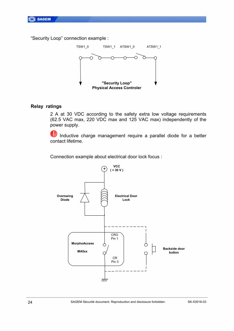
“Security Loop” connection example :
TSW1_0 TSW1_1 ATSW1_0 ATSW1_1
"Security Loop"Physical Access Controler
Relay ratings 2 A at 30 VDC according to the safety extra low voltage requirements (62.5 VAC max, 220 VDC max and 125 VAC max) independently of the power supply.
Inductive charge management require a parallel diode for a better contact lifetime. Connection example about electrical door lock focus :
MorphoAccess
MA5xx
CROPin 1
CRPin 3
+ VCC( < 30 V )
Electrical DoorLock
OverswingDiode
Backside doorbutton
24 SAGEM Sécurité document. Reproduction and disclosure forbidden. SK-53018-03
UUSSEERR IINNTTEERRFFAACCEE
The MorphoAccess™ terminal functions in three operational modes: access control with identification, access control with authentication or verification, and proxy mode. These various modes are detailed in the MA500 Series User Guide. Terminal configuration may be done locally ( keyboard , USB key ) or remotely (using the configuration Tool or MEMS software) , by modifying key parameter. For MA5xx terminal management , MEMS software release must be at least v6.2. MEMS™ : MorphoAccess Enrolment and Management System
SK-53018-03 SAGEM Sécurité document. Reproduction and disclosure forbidden. 25
MMOORRPPHHOOAACCCCEESSSSTTMM MMAA55XXXX SSEERRIIEESS TTEECCHHNNIICCAALL CCHHAARRAACCTTEERRIISSTTIICCSS
MMaann MMaacchhiinnee IInntteerrffaaccee
LCD display 128 x 64 pixels Alphanumeric and function keyboard ( 12 + 4 keypad ) Color LED for information Multi tone Buzzer Clock : +/- 4sec / day ( typical conditions ) , minimum 24 hours backup
BBiioommeettrryy
Based on SAGEM MSO Biometric Module, FIPS IQS certified: 500dpi optical sensor Template Data base:
3000 persons with 2 fingers 5 x 10000 pers with 2 fingers and MA-X license option
Identification: < 1,5s ( 1000 persons in database ) Authentication / verification: < 1s
PPeerriipphheerraallss iinntteerrffaacceess
Ethernet 10/100 Base T for remote control mode (terminal management) RS422 for remote control mode (terminal management) Wiegand (output) or Dataclock ISO2 (output) or COM (RS485 2 wires) for output information. Wiegand Input Or Dataclock Input to interface an external reader USB host for additional configuration Relay : 1 contact (open and closed) Tamper switch : Internal use (alarm message) and external contact. Anti theft : External contact (indoor MA5xx only)
26 SAGEM Sécurité document. Reproduction and disclosure forbidden. SK-53018-03

PPoowweerr ssuuppppllyy
9 to 16 Volts ± 5% and 1,5A peak power supply Cable cross section depends on the length 0. 75mm2 recommended. Consumption : 750mA maximum rms @12V ( < 1,5 A peak ) 350mA typical rms @12V Power Over Ethernet compatibility ( IEEE802.3 af ) :
Class 0 or Class 3 hub/switch equipment mandatory ( 15,4W )
MA5xx configurations POE Alternative A compliant with RJ45 and terminal blocks
POE Alternative B compliant with RJ45 only
OMA5xx configuration POE Alternative A compliant only “POE Alternative A” means power on data lines : Only 2 pairs are needed. “POE Alternative B” means power on 2 extra pairs lines : 4 pairs are required.
SSiizzee aanndd wweeiigghhtt
MA5xx version 160 x 145 x 75 mm 0,800 Kg
OMA5xx version 289 x 218 x 99 mm 2 Kg
SK-53018-03 SAGEM Sécurité document. Reproduction and disclosure forbidden. 27

EEnnvviirroonnnneemmeennttaall ccoonnddiittiioonnss
Operating temperature -10 °C to + 50 °C.
Operating humidity 10 % < RH < 80 %.
Storage temperature -20 °C to + 70 °C.
Storage humidity RH < 95 %.
Hardness MA5xx : IP30 ( indoor use only ) OMA5xx : IP65 (protection against rain and dust )
Light We recommend MorphoAccess™ installation within controlled lighting conditions. Avoid direct exposure of sensor to sunlight. Avoid intensive UV lights.
28 SAGEM Sécurité document. Reproduction and disclosure forbidden. SK-53018-03

RReeccoommmmeennddaattiioonnss
AArreeaass ccoonnttaaiinniinngg ccoommbbuussttiibblleess
It is strongly recommended that you do not install your SAGEM MorphoAccess™ in the vicinity of gas stations, petroleum processing facilities or any other facility containing flammable or combustible gasses or materials.
GGeenneerraall pprreeccaauuttiioonnss
• Do not attempt to repair your SAGEM MorphoAccess™ yourself. The manufacturer cannot be held responsible for any damage/accident that may result from attempts to repair components. Any work carried out by non-authorized personnel will invalidate your warranty.
• Use your SAGEM MorphoAccess™ with original accessories. Attempts to integrate the MorphoAccess™ with unapproved accessories will void your warranty.
• Do not use your MA5xx SAGEM MorphoAccess™ in damp areas (swimming pool...). Protect your MA5xx from water and other liquids.
• Do not expose your SAGEM MorphoAccess™ to extreme temperatures.
• Do not expose MorphoAccess™ sensor to direct sunlight. OMA visor is able to mask sunlight. With MA terminals, a complementary visor may be added.
• Due to electrostatic discharge, and depending on the environment, synthetic carpet should be avoided in areas where the SAGEM MorphoAccess™ has been installed.
SSppeecciiffiicc pprreeccaauuttiioonnss ffoorr rraaddiioo tteerrmmiinnaallss
It is recommended to install radio terminals ( MA520, MA521 , OMA520 and OMA521 ) at 30cm or more away from metallic elements, such as iron fixation or lift gate. Performances, in term of Contactless badges reading distance will decrease when metallic elements are in close proximity to the terminal. We advise persons with pacemaker or other electronic disposals against using this MA5x1 and OMA5x1 versions of MorphoAccess™ terminal.
SK-53018-03 SAGEM Sécurité document. Reproduction and disclosure forbidden. 29
EEtthheerrnneett ccoonnnneeccttiioonn
It is recommended to use a category 5 shielded cable (120 OHM). It is also strongly recommended to insert a repeater unit every 90 m. Extreme care must be taken while connecting Ethernet wire to the terminal block board since a low quality connection may strongly impact the Ethernet signal sensitivity. It is recommended to connect Rx+ and Rx- with the same twisted-pair wire (and to do the same with the Tx+/Tx- using different twisted-pair wire).
DDaattee // TTiimmee ssyynncchhrroonniizzaattiioonn
If you expect to use the MorphoAccessTM for application requiring time precision we recommend that you synchronize your terminal time with an external clock at regular intervals. The terminal clock has a +/- 40 10-6 ( ppm ) typical time deviation at +25°C. Roughly , +/- 4 sec per day. At +50°C, the time deviation may be up to –8 sec per day
CClleeaanniinngg pprreeccaauuttiioonnss
A dry cloth should be used, specially for fingerprint sensor. Acid liquids, alcohol or abrasive materials are forbidden.
WWaarrnniinngg
The manufacturer cannot be held responsible if the above recommendations are not followed or if the SAGEM MorphoAccess™ is incorrectly used.
BBiioommeettrriiccss TTeerrmmiinnaallss HHoott Liinnee
To Access this service, please contact us in order to get your login. Please send an email rather than call the hot line. Email: mailto:[email protected]
Phone : + 33 1 58 11 39 19 ( 9H00am to 5H00pm French Time , Monday to Friday )
30 SAGEM Sécurité document. Reproduction and disclosure forbidden. SK-53018-03

AAPPPPEENNDDIIXX 11 -- FFIINNGGEERRPPRRIINNTT PPLLAACCEEMMEENNTT RRUULLEESS
To ensure a good quality contact of your finger on the terminal you must leave your finger on the sensor until the sensor light is turned off.
Fingerprint Placement Fingerprint Orientation
Area containing most of the information
Fingerprint Inclination Fingerprint Rotation
SK-53018-03 SAGEM Sécurité document. Reproduction and disclosure forbidden. 31

AAPPPPEENNDDIIXX 22 –– RREELLAATTEEDD DDOOCCUUMMEENNTTSS
Administrator Information
MA500 Series User Guide
This document describes operating mode and terminal settings
MA500 Series Configuration Application User Guide
This document describes the configuration application processing
MA500 Series Parameters Guide
The complete description of terminal configuration files and registry keys This document gives also parameters default values.
MA500 Series Enrolment application User Guide
This document describes the local enrolment process and features
MA500 Series Log viewer User Guide
This document describes the log viewer process and features
Developer Information
MorphoAccess™ Host Interface Specification
A complete description of remote management commands
MorphoAccess™ Remote Messages Specification
Details how the MorphoAccessTM sends the access control result to a Central Security Controller
MorphoAccess™ Contactless Card Specification
This document describes the MorphoAccessTM contactless card feature
Support Tools
Configuration Tool User Guide
Configuration Tool user guide, via Ethernet
USB Tool User Guide
Configuration Tool user guide, via USB key
32 SAGEM Sécurité document. Reproduction and disclosure forbidden. SK-53018-03

MA500 Series Upgrade Tools User Guide
Upgrade Tool user guide about firmware upgrading procedures
Terminal Licence Management
Download a licence in MorphoAccessTM using “Terminal Licence Manager.exe” PC application.
SK-53018-03 SAGEM Sécurité document. Reproduction and disclosure forbidden. 33
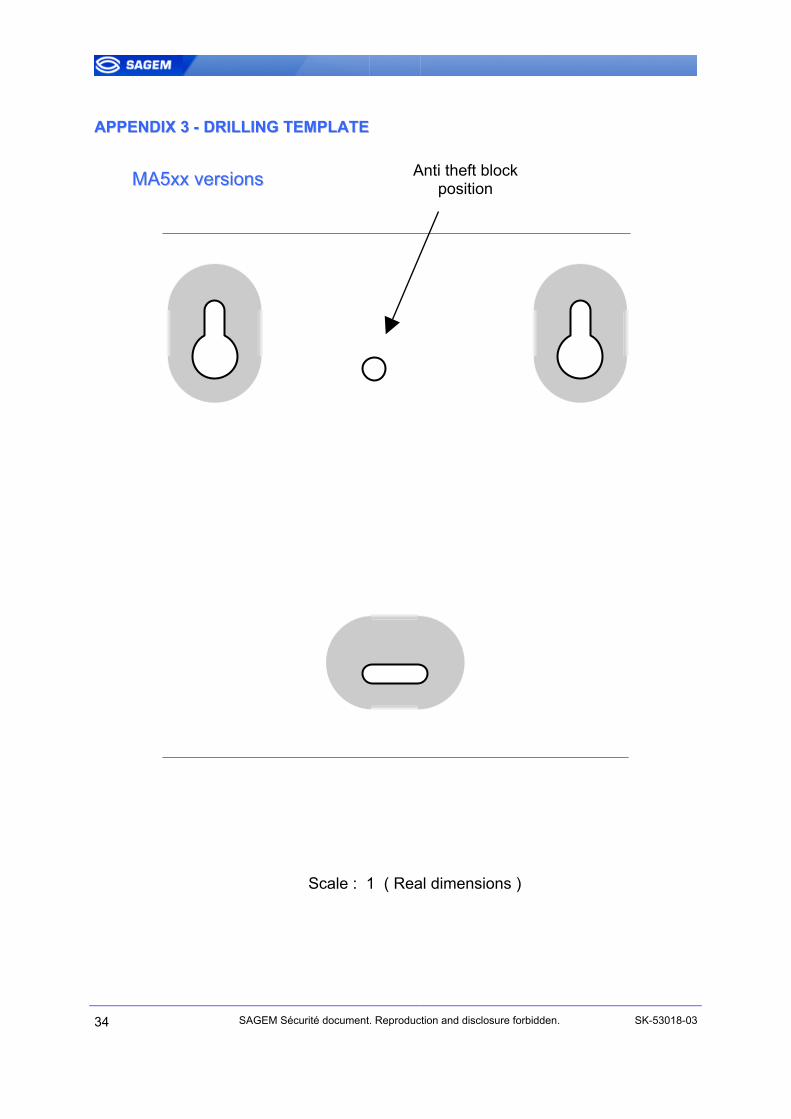
AAPPPPEENNDDIIXX 33 -- DDRRIILLLLIINNGG TTEEMMPPLLAATTEE
34 SAGEM Sécurité document. Reprod
MMAA55xxxx vveerrssiioonnss
Scale : 1 ( R
Anti theft block position
uction and disclosure forbidden. SK-53018-03
eal dimensions )
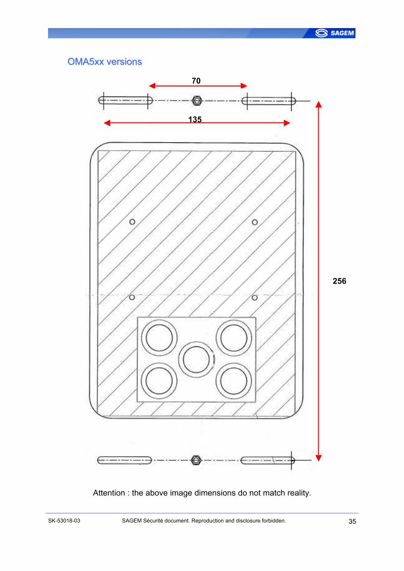
OOMMAA55xxxx vveerrssiioonnss
Attention : the above imag
SK-53018-03 SAGEM Sécurité document
70
5
13e dimensions do not match reality.
. Reproduction and disclosure forbidden.
256
35

SSUUPPPPOORRTT
CCuussttoommeerr sseerrvviiccee
SAGEM Sécurité SAV Terminaux Biométriques Boulevard Lénine - BP428 76805 Saint Etienne du Rouvray FRANCE Tel: +33 2 35 64 55 05
HHoottlliinnee
SAGEM Sécurité Support Terminaux Biométriques 24, Av du gros chêne 95610 Eragny – FRANCE [email protected] Tel: + 33 1 58 11 39 19 https://www.sagem-ds.com/biometrics-customersupport/Copyright ©2007 SAGEM Sécurité http://www.sagem-securite.com/
36 SAGEM Sécurité document. Reproduction and disclosure forbidden. SK-53018-03

Siège social: Le Ponant de Paris
27, rue Leblanc - 75512 PARIS CEDEX 15 - FRANCE