Embed Size (px)
Citation preview
ICAST2014: 25th
International Conference on Adaptive Structures and Technologies October 6-8th, 2014, The Hague, The Netherlands
1
Morphing Thickness in Airfoils using Pneumatic Flexible Tubes and Kirigami Honeycomb
Jian Sun1,2, Fabrizio Scarpa2*, Jinsong Leng1*
1 Center for Composite Materials and Structures, Harbin Institute of Technology, Harbin, China;
2 Advanced Composites Centre for Innovation and Science (ACCIS), University of Bristol, Bristol, UK
*Corresponding author. Email: [email protected], [email protected]
Abstract
The work describes, a concept to morph the thickness of airfoils using a combination of Pneumatic
Flexible Tubes (PFTs) within a Kirigami honeycomb configuration representing the wingbox structure.
The configuration of the honeycomb/inflatable tube structure is composed by a pair of flexible tubes
sandwiched between two custom honeycomb layouts. At zero input pressure the tube assumes a sinusoidal
shape, which is reduced to a straight configuration and increase of the airfoil thickness when pressure is
applied. An analytical model is developed to consider the actuation authority and thickness change
provided by the system proposed. The results are benchmarked against experimental tests carried out on a
reduced-scale demonstrator.
Keywords: Morphing Airfoil, Modelling, Inflatable Structure
NOMENCLATURE
P Input pressure in the tube
a Length of the side of hexagonal honeycomb
b Distance between the upper and lower surface in the section of the
compressed tube
s Distance between the upper and lower honeycomb
c Length of upper/lower surface in the section of the compressed tube
A Amplitude of the sinusoidal curves
ω Frequency of the sinusoidal curves
t1,t2 Offset Angle of the sinusoidal curves
B1,B2 Constant term of the sinusoidal curves
k Gradient of the curve of s-b
B3 Constant term of the curve of s-b
R Outside radius of the semicircle of the tube
R0 Original outside radius of the tube
t Thickness of the tube
Ft Shearing force on the two sides of semicircle unit
Ft0 Shearing force on the two sides of semicircle unit while the tube is a
ICAST2014: 25th
International Conference on Adaptive Structures and Technologies October 6-8th, 2014, The Hague, The Netherlands
2
circle
M Moment on the two sides of semicircle unit
ρ Central radius of the semicircle unit
ρ0 Original central radius of the semicircle unit
E Young’s Modules of the tube
I Rotary inertia of the semicircle unit about x axis
w Valid width of the semicircle unit
FR Recovery force of a tube caused by the circle structure
FS Recovery force of 1/4-period in a tube caused by stress
Δx Increment in x direction
ε Strain at x position
ΔFS Recovery force occurring at x position
Acircle Tube’s area in loop section
FP Force referring to input pressure
L Action length of the input pressure for a tube
G Loading force
P Input pressure in the tube
1. INTRODUCTION
During the last two decades morphing technologies have demonstrated their capability to
provide significant enhancement of the aircraft performance and broadening of the related flight
envelope [1-3]. Several types of morphing techniques have been developed in recent years, and
examples span from folding technologies for morphing wingtips to adaptive twist and variable
camber [4-6]. The performance of a wing in a specific flight condition depends also on geometry
properties of an airfoil provided by the maximum camber of the mean line and thickness
distribution along the chord [7]. A thick wing performs more efficiently from the aerodynamic
point of view at low speeds, while a thin wing is adapted to high speed flight [8, 9]. If the
thickness of the airfoil can vary in a controllable way over the chord length, the aircraft can have
a larger flight envelope and meet the demands of multiple missions [10]. An example of this
concept is the morphing airfoil wing prototype based on shape memory alloys (SMA) actuators
designed for subsonic cruise flight conditions, which has been tested in a subsonic wind tunnel
[11].
Honeycomb and cellular structures are extensively used in airframe and sandwich applications
for their high specific shear and bending stiffness, and recently have been proposed to morphing
applications due to their compliance [12-14]. In morphing applications, the honeycomb does not
change shape by itself, but needs the use of smart material within its core, like in the cases of
SMA [15, 16] or Shape Memory Polymers (SMP) [17]. An alternative concept to create an
adaptive honeycomb consists in using pressured fluid inside the cells. Variable camber wings
have been already designed based on the use of a pneumatic pressurised honeycomb to obtain an
adaptive configuration by applying either a uniform [18] or differential pressures at different cells
locations [19, 20]. Pressured flexible tubes can also be used within the honeycombs or in
segmented structures, such as prosthetic hands [21], robotic platforms [22-24], and biomimetic
beam-steering antenna concepts [25, 26].
ICAST2014: 25th
International Conference on Adaptive Structures and Technologies October 6-8th, 2014, The Hague, The Netherlands
3
The paper describes a new morphing airfoil thickness concept based on the use of a Kirigami
hexagonal honeycomb supporting an inflatable tube structure, which provides the shape change
of the wingbox. Kirigami is the ancient Japanese art of folding and cutting paper spread in Asia
since the 17th
century, and it is particularly apt to build cellular structures with complex shapes
using different types of thermosets and thermoplastics composites [27-30], as well as other metal
substrates. An analytical model based on the geometry of the tube and approximations of the
output force behaviour of the tube itself is presented. A demonstrator of the morphing inflatable
honeycomb structure has also been produced, showing a general good agreement with the
predictions provided by the model in terms of displacement-pressure actuation. A prototype of
morphing airfoil has also been fabricated to further demonstrate the feasibility of the concept.
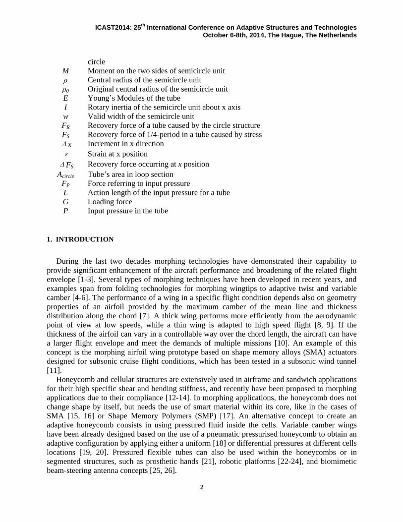
2. Morphing thickness in airfoil Concept
The morphing thickness airfoil structure consists in a cellular wingbox with Pneumatic Flexible Tubes
(PFTs) as actuators (Figure 1). The tubes are installed horizontally between the upper and lower hexagonal
honeycomb wingbox. When the pressure inside the tube is zero, the tube is contracted to follow an
approximate sinusoidal shape. The input pressure in the inflatable tubes can control the thickness of the
wing section. In the demonstrator developed in this work, a polyurethane (PU) foam filler is used to fill
the cellular wingbox to increase the in-plane stiffness and guarantee a smooth change of the thickness to
follow the aerodynamic shape.
P=0
P>0
Figure 1. Schematic of the morphing thickness airfoil concept
3. Modeling
3.1 Geometric Model
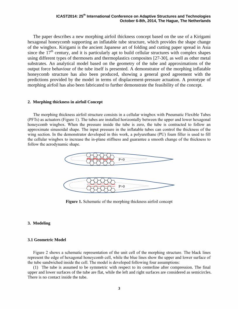
Figure 2 shows a schematic representation of the unit cell of the morphing structure. The black lines
represent the edge of hexagonal honeycomb cell, while the blue lines show the upper and lower surface of
the tube sandwiched inside the cell. The model is developed following four assumptions:
(1) The tube is assumed to be symmetric with respect to its centerline after compression. The final
upper and lower surfaces of the tube are flat, while the left and right surfaces are considered as semicircles.
There is no contact inside the tube.
ICAST2014: 25th
International Conference on Adaptive Structures and Technologies October 6-8th, 2014, The Hague, The Netherlands
4
(2) Before compression (actuation) the upper and lower surfaces are sinusoidal.
(3) No sliding is present between the tubes and the honeycomb.
(4) The honeycomb is considered to simply transfer the load, and acts as a rigid body during the
deformation of the tubes.
a
s
w
s
b
x
y
I
II
a
Figure 2. Morphing structure unit in rectangular coordinates
The two curves defining the shape of the tubes are described with the following equations:
1 1sin( )Iy A x t B (1)
2 2sin( )IIy A x t B (2)
Where 2
3a
and 1 2
2t t
.
The upper curve passes through point3
,2
a a
, therefore the term 1
3
2 2
AB a is constant. The
point 3
,2 2
as a
belongs to the lower curve, as a consequence the value of B2 is 2
3
2 2
AB s a .
By inspection the following relation holds:
2 1b B B s A (3)
Assuming that a linear relationship exists between the terms b and s:
3b ks B (4)
When 02s R ,
02b R and 3
2s a , 0b , the coefficients k and B3 assume the following forms:
0
0
2
32
2
Rk
R a
, 3
3
2B ka (5)
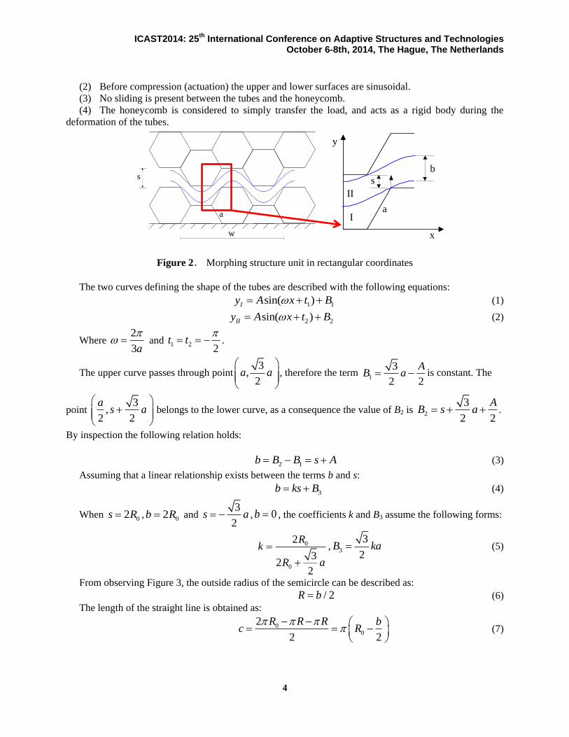
From observing Figure 3, the outside radius of the semicircle can be described as:
/ 2R b (6)
The length of the straight line is obtained as:
00
2
2 2
R R R bc R
(7)
ICAST2014: 25th
International Conference on Adaptive Structures and Technologies October 6-8th, 2014, The Hague, The Netherlands
5
The relationships between the terms b, c, and A versus s are shown in Figure 4 for
0 2.75R mm and 6a mm . The terms A and c decrease linearly with the increase of s, while the
constant b has an opposite behavior.
t
R
Pb
c
z
y
Figure 3. Geometry of a compressed tube Figure 4. Distances between the upper and lower
surfaces versus the internal height of the tube cell
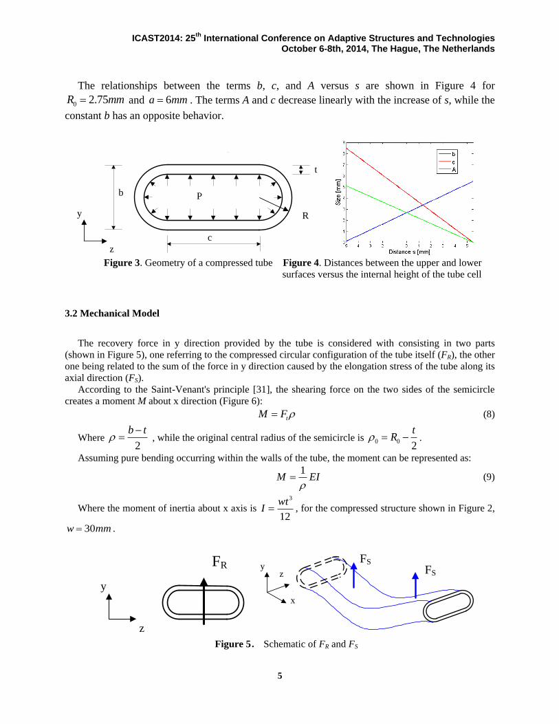
3.2 Mechanical Model
The recovery force in y direction provided by the tube is considered with consisting in two parts
(shown in Figure 5), one referring to the compressed circular configuration of the tube itself (FR), the other
one being related to the sum of the force in y direction caused by the elongation stress of the tube along its
axial direction (FS).
According to the Saint-Venant's principle [31], the shearing force on the two sides of the semicircle
creates a moment M about x direction (Figure 6):
tM F (8)
Where 2
b t
, while the original central radius of the semicircle is 0 0
2
tR .
Assuming pure bending occurring within the walls of the tube, the moment can be represented as:
1M EI
(9)
Where the moment of inertia about x axis is 3
12
wtI , for the compressed structure shown in Figure 2,
30w mm .
FR
z
y
FS
FS
x
yz
Figure 5. Schematic of FR and FS
ICAST2014: 25th
International Conference on Adaptive Structures and Technologies October 6-8th, 2014, The Hague, The Netherlands
6
M
M
ρρ
Ft
Ft
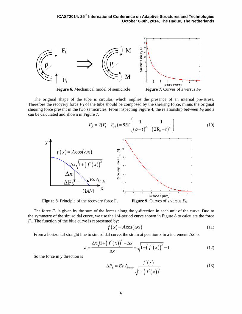
Figure 6. Mechanical model of semicircle Figure 7. Curves of s versus FR
The original shape of the tube is circular, which implies the presence of an internal pre-stress.
Therefore the recovery force FR of the tube should be composed by the shearing force, minus the original
shearing force present in the two semicircles. From inspecting Figure 4, the relationship between FR and s
can be calculated and shown in Figure 7.
0 2 2
0
1 12( ) 8
2R t tF F F EI
b t R t
(10)
x
y
ΔFS
Δx
3a/4
2
'1x f x
cosf x A x
circleE A
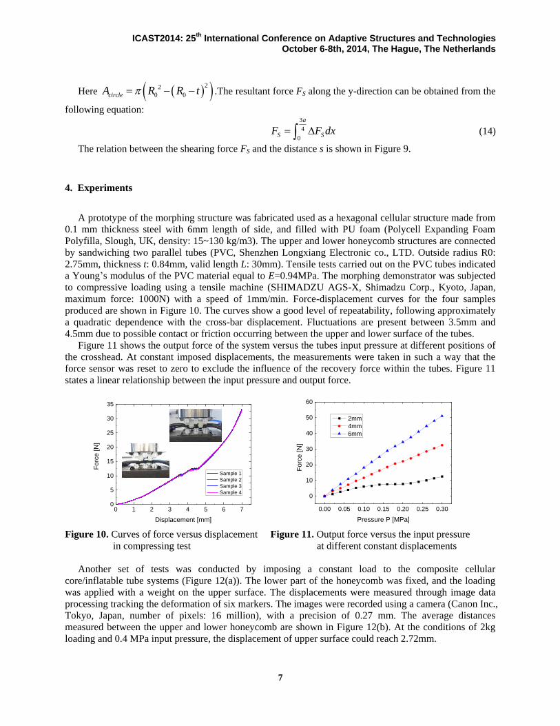
Figure 8. Principle of the recovery force FS Figure 9. Curves of s versus FS
The force FS is given by the sum of the forces along the y-direction in each unit of the curve. Duo to
the symmetry of the sinusoidal curve, we use the 1/4-period curve shown in Figure 8 to calculate the force
FS. The function of the blue curve is represented by:
cosf x A x (11)
From a horizontal straight line to sinusoidal curve, the strain at position x in a increment x is
2'
2'
11 1
x f x xf x
x
(12)
So the force in y direction is
'
2'1
S circle
f xF E A
f x
(13)
ICAST2014: 25th
International Conference on Adaptive Structures and Technologies October 6-8th, 2014, The Hague, The Netherlands
7
Here 22
0 0circleA R R t .The resultant force FS along the y-direction can be obtained from the
following equation: 3
4
0
a
S SF F dx (14)
The relation between the shearing force FS and the distance s is shown in Figure 9.
4. Experiments
A prototype of the morphing structure was fabricated used as a hexagonal cellular structure made from
0.1 mm thickness steel with 6mm length of side, and filled with PU foam (Polycell Expanding Foam
Polyfilla, Slough, UK, density: 15~130 kg/m3). The upper and lower honeycomb structures are connected
by sandwiching two parallel tubes (PVC, Shenzhen Longxiang Electronic co., LTD. Outside radius R0:
2.75mm, thickness t: 0.84mm, valid length L: 30mm). Tensile tests carried out on the PVC tubes indicated
a Young’s modulus of the PVC material equal to E=0.94MPa. The morphing demonstrator was subjected
to compressive loading using a tensile machine (SHIMADZU AGS-X, Shimadzu Corp., Kyoto, Japan,
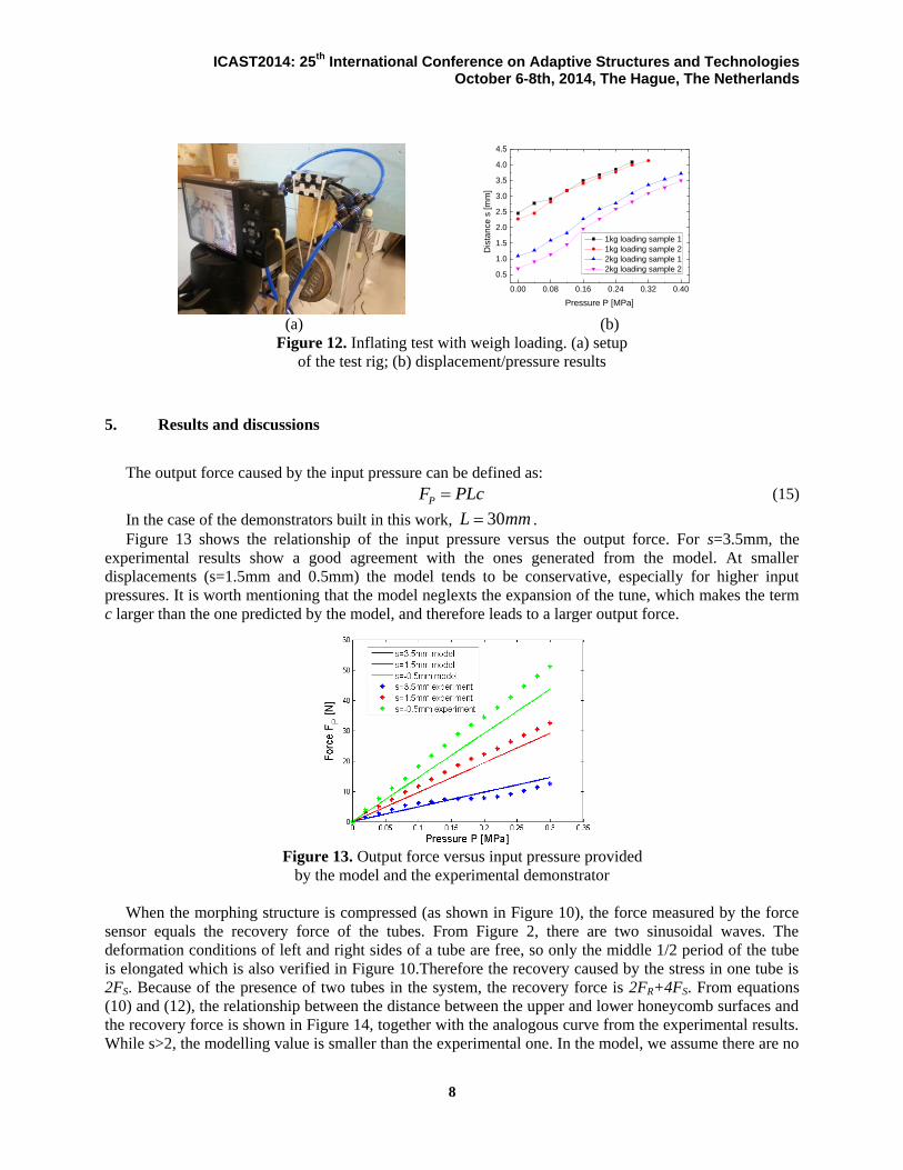
maximum force: 1000N) with a speed of 1mm/min. Force-displacement curves for the four samples
produced are shown in Figure 10. The curves show a good level of repeatability, following approximately
a quadratic dependence with the cross-bar displacement. Fluctuations are present between 3.5mm and
4.5mm due to possible contact or friction occurring between the upper and lower surface of the tubes.
Figure 11 shows the output force of the system versus the tubes input pressure at different positions of
the crosshead. At constant imposed displacements, the measurements were taken in such a way that the
force sensor was reset to zero to exclude the influence of the recovery force within the tubes. Figure 11
states a linear relationship between the input pressure and output force.
0 1 2 3 4 5 6 70
5
10
15
20
25
30
35
Fo
rce
[N
]
Displacement [mm]
Sample 1
Sample 2
Sample 3
Sample 4
0.00 0.05 0.10 0.15 0.20 0.25 0.30
0
10
20
30
40
50
60
Forc
e [
N]
Pressure P [MPa]
2mm
4mm
6mm
Figure 10. Curves of force versus displacement Figure 11. Output force versus the input pressure
in compressing test at different constant displacements
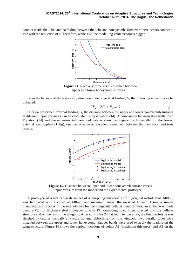
Another set of tests was conducted by imposing a constant load to the composite cellular
core/inflatable tube systems (Figure 12(a)). The lower part of the honeycomb was fixed, and the loading
was applied with a weight on the upper surface. The displacements were measured through image data
processing tracking the deformation of six markers. The images were recorded using a camera (Canon Inc.,
Tokyo, Japan, number of pixels: 16 million), with a precision of 0.27 mm. The average distances
measured between the upper and lower honeycomb are shown in Figure 12(b). At the conditions of 2kg
loading and 0.4 MPa input pressure, the displacement of upper surface could reach 2.72mm.
ICAST2014: 25th
International Conference on Adaptive Structures and Technologies October 6-8th, 2014, The Hague, The Netherlands
8
0.00 0.08 0.16 0.24 0.32 0.40
0.5
1.0
1.5
2.0
2.5
3.0
3.5
4.0
4.5
Dis
tan
ce
s [
mm
]
Pressure P [MPa]
1kg loading sample 1
1kg loading sample 2
2kg loading sample 1
2kg loading sample 2
(a) (b)
Figure 12. Inflating test with weigh loading. (a) setup
of the test rig; (b) displacement/pressure results
5. Results and discussions
The output force caused by the input pressure can be defined as:
PF PLc (15)
In the case of the demonstrators built in this work, 30L mm .
Figure 13 shows the relationship of the input pressure versus the output force. For s=3.5mm, the
experimental results show a good agreement with the ones generated from the model. At smaller
displacements (s=1.5mm and 0.5mm) the model tends to be conservative, especially for higher input
pressures. It is worth mentioning that the model neglexts the expansion of the tune, which makes the term
c larger than the one predicted by the model, and therefore leads to a larger output force.
Figure 13. Output force versus input pressure provided
by the model and the experimental demonstrator
When the morphing structure is compressed (as shown in Figure 10), the force measured by the force
sensor equals the recovery force of the tubes. From Figure 2, there are two sinusoidal waves. The
deformation conditions of left and right sides of a tube are free, so only the middle 1/2 period of the tube
is elongated which is also verified in Figure 10.Therefore the recovery caused by the stress in one tube is
2FS. Because of the presence of two tubes in the system, the recovery force is 2FR+4FS. From equations
(10) and (12), the relationship between the distance between the upper and lower honeycomb surfaces and
the recovery force is shown in Figure 14, together with the analogous curve from the experimental results.
While s>2, the modelling value is smaller than the experimental one. In the model, we assume there are no
ICAST2014: 25th
International Conference on Adaptive Structures and Technologies October 6-8th, 2014, The Hague, The Netherlands
9
contact inside the tube, and no sliding between the tube and honeycomb. However, there occurs contact at
s=2 with the reduction of s. Therefore, while s<2, the modelling value becomes bigger.
Figure 14. Recovery force versus distance between
upper and lower honeycomb surfaces
From the balance of the forces in y direction under a vertical loading G, the following equation can be
obtained.
2 2R S PF F F G (16)
Under a prescribed external loading G, the distance between the upper and lower honeycomb surfaces
at different input pressures can be calculated using equation (14). A comparison between the results from
Equation (14) and the experimental measured data is shown in Figure 15. Especially for the lowest
external load applied (1 Kg), one can observe an excellent agreement between the theoretical and tests
results.
Figure 15. Distance between upper and lower honeycomb surface versus
input pressure from the model and the experimental prototype
A prototype of a reduced-scale model of a morphing thickness airfoil (original airfoil: NACA0030)
was fabricated with a chord of 140mm and maximum initial thickness of 43 mm. Using a similar
manufacturing process to the one adopted for the composite cellular demonstrator, an airfoil was made
using a 0.1mm thickness steel honeycomb, with PU expanding foam filler injected into the cellular
structure and on the rest of the wingbox. After curing for 24h at room temperature, the final prototype was
finished by cutting manually any extra polymer debording from the wingbox. Two parallel tubes were
installed between the upper and lower honeycomb. Rubber bands were used to apply the loading on the
wing structure. Figure 16 shows the vertical locations of points A1 (maximum thickness) and A2 on the
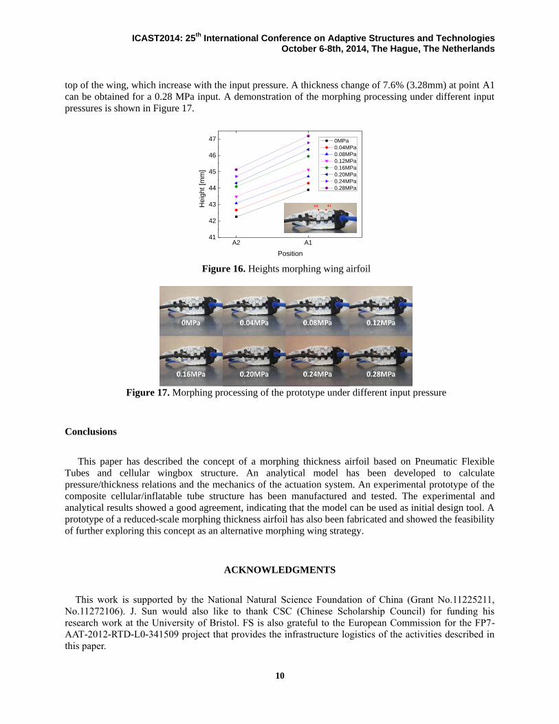
ICAST2014: 25th
International Conference on Adaptive Structures and Technologies October 6-8th, 2014, The Hague, The Netherlands
10
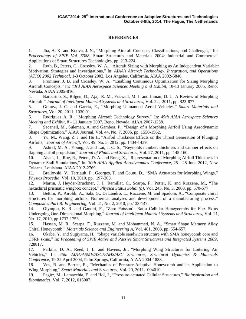
top of the wing, which increase with the input pressure. A thickness change of 7.6% (3.28mm) at point A1
can be obtained for a 0.28 MPa input. A demonstration of the morphing processing under different input
pressures is shown in Figure 17.
A2 A141
42
43
44
45
46
47
Heig
ht
[mm
]
Position
0MPa
0.04MPa
0.08MPa
0.12MPa
0.16MPa
0.20MPa
0.24MPa
0.28MPa
Figure 16. Heights morphing wing airfoil
Figure 17. Morphing processing of the prototype under different input pressure
Conclusions
This paper has described the concept of a morphing thickness airfoil based on Pneumatic Flexible
Tubes and cellular wingbox structure. An analytical model has been developed to calculate
pressure/thickness relations and the mechanics of the actuation system. An experimental prototype of the
composite cellular/inflatable tube structure has been manufactured and tested. The experimental and
analytical results showed a good agreement, indicating that the model can be used as initial design tool. A
prototype of a reduced-scale morphing thickness airfoil has also been fabricated and showed the feasibility
of further exploring this concept as an alternative morphing wing strategy.
ACKNOWLEDGMENTS
This work is supported by the National Natural Science Foundation of China (Grant No.11225211,
No.11272106). J. Sun would also like to thank CSC (Chinese Scholarship Council) for funding his
research work at the University of Bristol. FS is also grateful to the European Commission for the FP7-
AAT-2012-RTD-L0-341509 project that provides the infrastructure logistics of the activities described in
this paper.
ICAST2014: 25th
International Conference on Adaptive Structures and Technologies October 6-8th, 2014, The Hague, The Netherlands
11
REFERENCES
1. Jha, A. K. and Kudva, J. N., “Morphing Aircraft Concepts, Classifications, and Challenges,” In:
Proceedings of SPIE Vol. 5388, Smart Structures and Materials 2004: Industrial and Commercial
Applications of Smart Structures Technologies, pp. 213-224.
2. Roth, B., Peters, C., Crossley, W. A., “Aircraft Sizing with Morphing as An Independent Variable:
Motivation, Strategies and Investigations,” In: AIAA's Aircraft Technology, Integration, and Operations
(ATIO) 2002 Technical, 1-3 October 2002, Los Angeles, California, AIAA 2002-5840.
3. Frommer, J. B. and Crossley, W. A., “Enabling Continuous Optimization for Sizing Morphing
Aircraft Concepts,” In: 43rd AIAA Aerospace Sciences Meeting and Exhibit, 10-13 January 2005, Reno,
Nevada. AIAA 2005-816.
4. Barbarino, S., Bilgen, O., Ajaj, R. M., Friswell, M. I. and Inman, D. J., A Review of Morphing
Aircraft,” Journal of Intelligent Material Systems and Structures, Vol. 22, 2011, pp. 823-877.
5. Gomez, J. C. and Garcia, E., “Morphing Unmanned Aerial Vehicles,” Smart Materials and
Structures, Vol. 20, 2011, 1030.01.
6. Rodriguez A. R., “Morphing Aircraft Technology Survey,” In: 45th AIAA Aerospace Sciences
Meeting and Exhibit, 8 - 11 January 2007, Reno, Nevada. AIAA 2007-1258.
7. Secanell, M., Suleman, A. and Gamboa, P., “Design of a Morphing Airfoil Using Aerodynamic
Shape Optimization,” AIAA Journal, Vol. 44, No. 7, 2006, pp. 1550-1562.
8. Yu, M., Wang, Z. J. and Hu H, “Airfoil Thickness Effects on the Thrust Generation of Plunging
Airfoils,” Journal of Aircraft, Vol. 49, No. 5, 2012, pp. 1434-1439.
9. Ashraf, M. A., Young, J. and Lai, J. C. S., “Reynolds number, thickness and camber effects on
flapping airfoil propulsion,” Journal of Fluids and Structures, Vol. 27, 2011, pp. 145-160.
10. Ahaus, L., Roe, R., Peters, D. A. and Rong, X., “Representation of Morphing Airfoil Thickness in
Dynamic Stall Simulations,” In: 30th AIAA Applied Aerodynamics Conference, 25 - 28 June 2012, New
Orleans, Louisiana. AIAA 2012-2769.
11. Brailovski, V., Terriault, P., Georges, T. and Coutu, D., “SMA Actuators for Morphing Wings,”
Physics Procedia, Vol. 10, 2010, pp. 197-203.
12. Martin, J, Heyder-Bruckner, J. J., Remillat, C., Scarpa, F., Potter, K. and Ruzzene, M., “The
hexachiral prismatic wingbox concept,” Physica Status Solidi (b), Vol. 245, No. 3, 2008, pp. 570-577
13. Bettini, P., Airoldi, A., Sala, G., Di Landro, L., Ruzzene, M. and Spadoni, A., “Composite chiral
structures for morphing airfoils: Numerical analyses and development of a manufacturing process,”
Composites Part B: Engineering, Vol. 41, No. 2, 2010, pp.133-147.
14. Olympio, K. R. and Gandhi, F., “Zero Poisson’s Ratio Cellular Honeycombs for Flex Skins
Undergoing One-Dimensional Morphing,” Journal of Intelligent Material Systems and Structures, Vol. 21,
No. 17, 2010, pp.1737-1753
15. Hassan, M. R., Scarpa, F., Ruzzene, M. and Mohammed, N. A., “Smart Shape Memory Alloy
Chiral Honeycomb,” Materials Science and Engineering A, Vol. 481, 2008, pp. 654-657.
16. Okabe, Y. and Sugiyama, H., “Shape variable sandwich structure with SMA honeycomb core and
CFRP skins,” In: Proceeding of SPIE Active and Passive Smart Structures and Integrated Systems 2009,
728817.
17. Perkins, D. A., Reed, J. L. and Havens, Jr., “Morphing Wing Structures for Loitering Air
Vehicles,” In: 45th AIAA/ASME/ASCE/AHS/ASC Structures, Structural Dynamics & Materials
Conference, 19-22 April 2004, Palm Springs, California, AIAA 2004-1888.
18. Vos, R. and Barrett, R., “Mechanics of Pressure-Adaptive Honeycomb and its Application to
Wing Morphing,” Smart Materials and Structures, Vol. 20, 2011. 094010.
19. Pagitz, M., Lamacchia, E. and Hol, J., “Pressure-actuated Cellular Structures,” Bioinspiration and
Biomimetics, Vol. 7, 2012, 016007.
ICAST2014: 25th
International Conference on Adaptive Structures and Technologies October 6-8th, 2014, The Hague, The Netherlands
12
20. Pagitz, M. and Bold, J., “Shape-changing Shell-like Structures,” Bioinspiration and Biomimetics,
Vol. 8, 2013, 016010.
21. Schulz, S., Pylatiuk, C., Reischl, M., Martin, J., Mikut, R. and Bretthauer, G., “A Hydraulically
Driven Multifunctional Prosthetic Hand,” Robotica, Vol. 23, 2005, pp. 293-299.
22. Berring, J., Kianfar, K., Lira, C., Menon, C. and Scarpa, F., “A Smart Hydraulic Joint for Future
Implementation in Robotic Structures,” Robotica, Vol. 28, No. 07, 2010, pp. 1045-1056.
23. Menon, C. and Lira, C., “Active Articulation for Future Space Applications Inspired by the
Hydraulic System of Spiders,” Bioinspiration and Biomimetics, Vol. 1, 2006, pp. 52-61.
24. Lira, C., Menon, C., Kianfar, K. and Scarpa, F., “Bioinspired Hydraulic Joint for Highly
Redundant Robotic Platforms,” In: ASME/IFToMM International Conference on Reconfigurable
Mechanisms and Robots, 2009, pp. 434-438.
25. Chang, B., Chew, A., Naghshineh, N. and Menon, C., “A Spatial Bending Fluidic Actuator:
Fabrication and Quasi-Static Characteristics,” Smart Materials and Structures, Vol. 21, 2012, 045008.
26. Mazlouman, S. J., Chang, B., Mahanfar, A., Vaughan, R. G., and Menon, C., “Beam-Steering
Antenna using Bending Fluidic Actuators,” IEEE Transactions on Antennas and Propagation, Vol. 61,
No. 10, 2013, pp. 5287-5290.
27. Nojima, T. and Saito, K., “Development of Newly Designed Ultra-Light Core Structures,” JSME
International Journal Series A, Vol. 49, No. 1, 2006, pp. 38-42.
28. Saito, K., Agnese, F. and Scarpa, F., “A Cellular Kirigami Morphing Wingbox Concept,” Journal
of Intelligent Material Systems and Structures, Vol. 22, No. 9, 2011, pp. 935-944.
29. Chen, Y. J., Scarpa, F., Remillat, C., Farrow, I., Liu, Y. J. and Leng, J. S., “Curved Kirigami
SILICOMB cellular structures with zero Poisson’s ratio for large deformations and morphing,” Journal of
Intelligent Material Systems and Structures, 2013, DOI: 10.1177/1045389X13502852.
30. Virk, K., Monti, A., Trehard, T., Marsh, M., Hazra, K., Boba, K., Remillat, C. D. L., Scarpa, F.
and I. R. Farrow, “SILICOMB PEEK Kirigami cellular structures: mechanical response and energy
dissipation through zero and negative stiffness,” Smart Materials and Structures, Vol. 22, No. 8, 2013,
084014.
31. Gregory, R. D. and Wan, F. Y. M., “On Plate Theories and Saint-Venant’S Principle,”
International Journal of Solids and Structures, Vol. 21, No. 10, 1985, pp. 1005-1024