Embed Size (px)
Citation preview

XMORE XMR-T _ 1
XMR-T
MORE
MORE ADVANCED,HIGH-END IEDs FOR PROTECTING, MONITORING AND CONTROLLING ELECTRIC POWER SYSTEMS.
eXtended MOdular RElays
XMORE XMR-T _ 2XMORE XMR-T _ 2
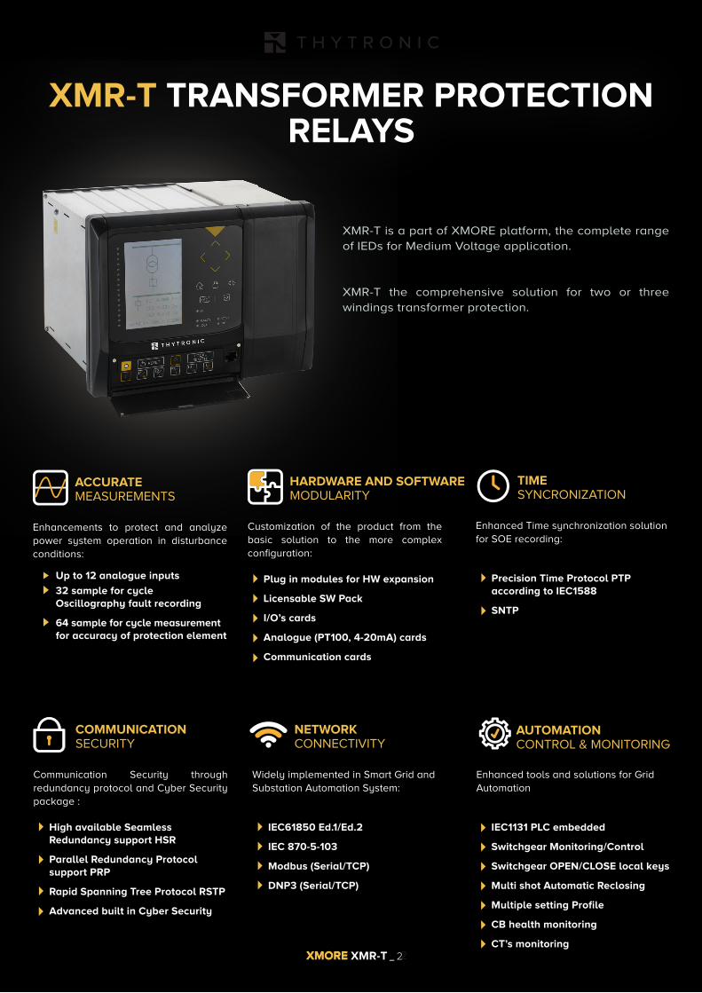
XMR-T TRANSFORMER PROTECTION RELAYS
XMR-T is a part of XMORE platform, the complete range of IEDs for Medium Voltage application.
XMR-T the comprehensive solution for two or three windings transformer protection.
Enhancements to protect and analyze power system operation in disturbance conditions:
ACCURATEMEASUREMENTS
Customization of the product from the basic solution to the more complex configuration:
Plug in modules for HW expansion
Licensable SW Pack
I/O’s cards
Analogue (PT100, 4-20mA) cards
Communication cards
HARDWARE AND SOFTWARE MODULARITY
Enhanced Time synchronization solutionfor SOE recording:
Precision Time Protocol PTP according to IEC1588
SNTP
TIMESYNCRONIZATION
► Up to 12 analogue inputs
► 32 sample for cycle Oscillography fault recording
► 64 sample for cycle measurement for accuracy of protection element
Communication Security through redundancy protocol and Cyber Security package :
High available Seamless Redundancy support HSR
Parallel Redundancy Protocol support PRP
Rapid Spanning Tree Protocol RSTP
Advanced built in Cyber Security
COMMUNICATIONSECURITY
Widely implemented in Smart Grid andSubstation Automation System:
IEC61850 Ed.1/Ed.2
IEC 870-5-103
Modbus (Serial/TCP)
DNP3 (Serial/TCP)
NETWORKCONNECTIVITY
Enhanced tools and solutions for Grid Automation
IEC1131 PLC embedded
Switchgear Monitoring/Control
Switchgear OPEN/CLOSE local keys
Multi shot Automatic Reclosing
Multiple setting Profile
CB health monitoring
CT’s monitoring
AUTOMATION CONTROL & MONITORING
XMORE XMR-T _ 3
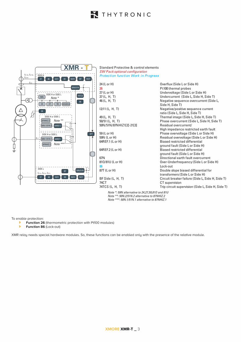
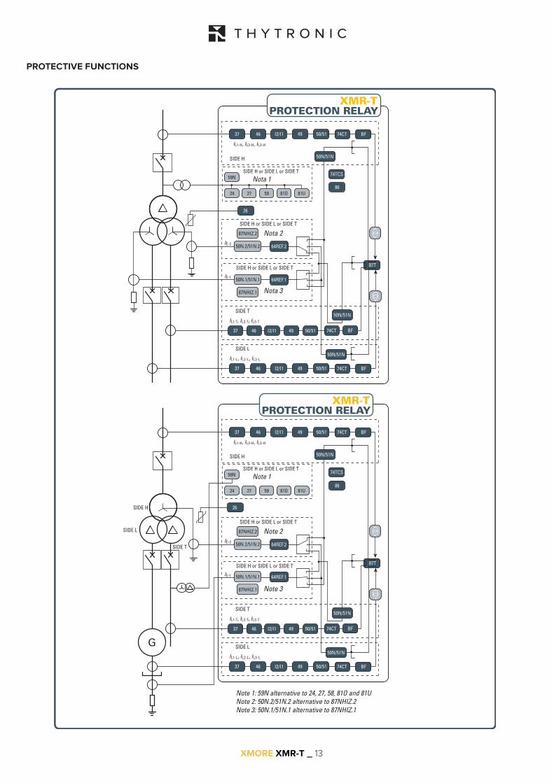
Note *: 59N alternative to 24,27,59,81O and 81UNote **: 50N.2/51N.2 alternative to 87NHIZ.2Note ***: 50N.1/51N.1 alternative to 87NHIZ.1
IL1-H, IL2-H, IL3-H
87T
74TCS
IE-1
IE-2
26
Note *
Note **
Note ***
50N/51N
59N
I2/I14637 49 50/51 BF 74CT
74CT
24 27 59 81O/81U
SIDE H or SIDE L
SIDE H or SIDE L
SIDE H
87NHIZ.1
50N.1/51N.1 64REF.1
SIDE H or SIDE L
IL1-L, IL2-L, IL3-L
50N/51NSIDE L
I2/I14637 49 50/51
BF
XMR - T
87NHIZ.2
50N.1/51N.2 64REF.2
Standard Protective & control elementsSW Pack optional configurationProtection function Work in Progress
24 (L or H) Overflux (Side L or Side H)26 Pt100 thermal probes27 (L or H) Undervoltage (Side L or Side H)37 (L, H, T) Undercurrent (Side L, Side H, Side T)46 (L, H, T) Negative sequence overcurrent (Side L, Side H, Side T)I2/I1 (L, H, T) Negative/positive sequence current ratio (Side L, Side H, Side T)49 (L, H, T) Thermal image (Side L, Side H, Side T)50/51 (L, H, T) Phase overcurrent (Side L, Side H, Side T)50N/51N/87NHIZ1[2]-21[3] Residual overcurrent/ High impedance restricted earth fault59 (L or H) Phase overvoltage (Side L or Side H)59N (L or H) Residual overvoltage (Side L or Side H)64REF.1 (L or H) Biased restricted differential ground fault (Side L or Side H)64REF.2 (L or H) Biased restricted differential ground fault (Side L or Side H)67N Directional earth fault overcurrent81O/81U (L or H) Over-Underfrequency (Side L or Side H)86 Lock-out87T (L or H) Double slope biased differential for transformers (Side L or Side H)BF Side (L, H, T) Circuit breaker failure (Side L, Side H, Side T)74CT CT supervision74TCS (L, H, T) Trip circuit supervision (Side L, Side H, Side T)
86
To enable protection: ► Function 26 (thermometric protection with Pt100 modules) ► Function 86 (Lock-out) XMR relay needs special hardware modules. So, these functions can be enabled only with the presence of the relative module.
XMORE XMR-T _ 4
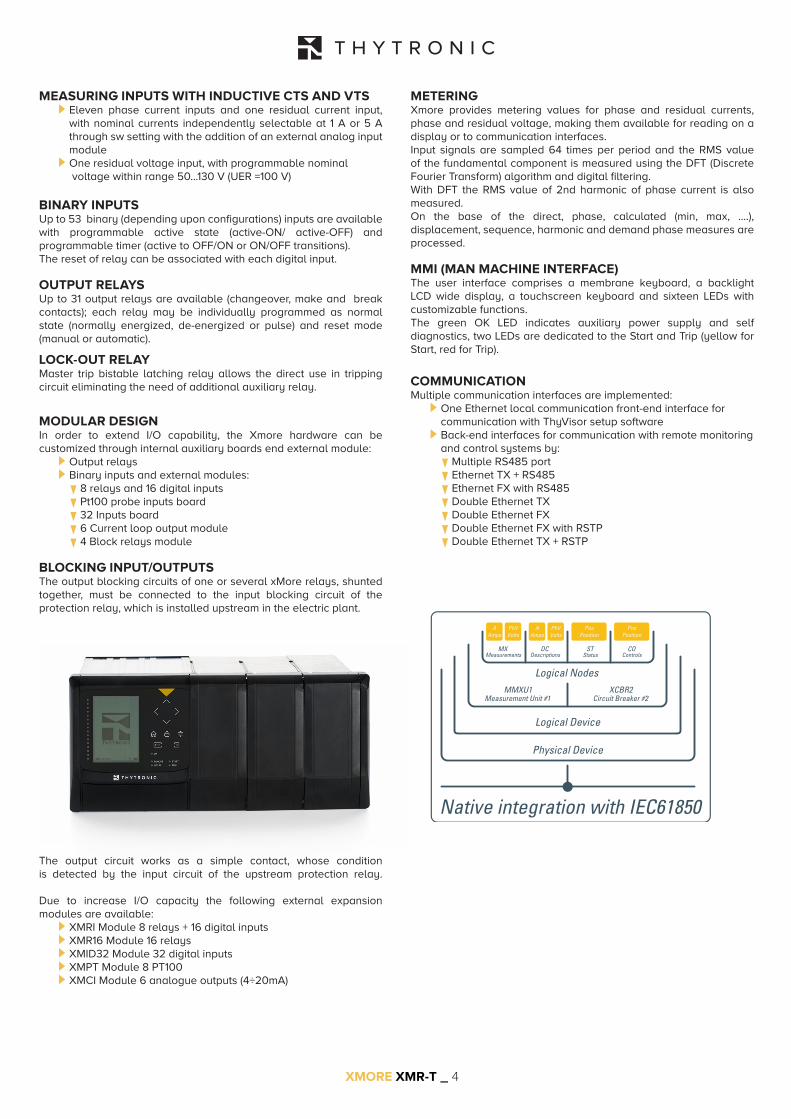
METERINGXmore provides metering values for phase and residual currents, phase and residual voltage, making them available for reading on a display or to communication interfaces.Input signals are sampled 64 times per period and the RMS value of the fundamental component is measured using the DFT (Discrete Fourier Transform) algorithm and digital filtering.With DFT the RMS value of 2nd harmonic of phase current is also measured.On the base of the direct, phase, calculated (min, max, ....), displacement, sequence, harmonic and demand phase measures are processed.
MMI (MAN MACHINE INTERFACE)The user interface comprises a membrane keyboard, a backlight LCD wide display, a touchscreen keyboard and sixteen LEDs with customizable functions.The green OK LED indicates auxiliary power supply and self diagnostics, two LEDs are dedicated to the Start and Trip (yellow for Start, red for Trip).
COMMUNICATIONMultiple communication interfaces are implemented: ►One Ethernet local communication front-end interface for communication with ThyVisor setup software ►Back-end interfaces for communication with remote monitoring and control systems by: ▼ Multiple RS485 port ▼Ethernet TX + RS485 ▼Ethernet FX with RS485 ▼Double Ethernet TX ▼Double Ethernet FX ▼Double Ethernet FX with RSTP ▼Double Ethernet TX + RSTP
Physical Device
Logical Device
MMXU1Measurement Unit #1
MXMeasurements
DCDescriptions
STStatus
COControls
XCBR2Circuit Breaker #2
Logical Nodes
AAmps
AAmps
PhVVolts
PhVVolts
PosPosition
PosPosition
Native integration with IEC61850
MEASURING INPUTS WITH INDUCTIVE CTS AND VTS ►Eleven phase current inputs and one residual current input, with nominal currents independently selectable at 1 A or 5 A through sw setting with the addition of an external analog input module ►One residual voltage input, with programmable nominal voltage within range 50...130 V (UER =100 V)
BINARY INPUTSUp to 53 binary (depending upon configurations) inputs are available with programmable active state (active-ON/ active-OFF) and programmable timer (active to OFF/ON or ON/OFF transitions).The reset of relay can be associated with each digital input.
OUTPUT RELAYSUp to 31 output relays are available (changeover, make and break contacts); each relay may be individually programmed as normal state (normally energized, de-energized or pulse) and reset mode (manual or automatic).
LOCK-OUT RELAYMaster trip bistable latching relay allows the direct use in tripping circuit eliminating the need of additional auxiliary relay.
MODULAR DESIGNIn order to extend I/O capability, the Xmore hardware can be customized through internal auxiliary boards end external module: ►Output relays ►Binary inputs and external modules: ▼8 relays and 16 digital inputs ▼Pt100 probe inputs board ▼32 Inputs board ▼6 Current loop output module ▼4 Block relays module
BLOCKING INPUT/OUTPUTSThe output blocking circuits of one or several xMore relays, shunted together, must be connected to the input blocking circuit of the protection relay, which is installed upstream in the electric plant.
The output circuit works as a simple contact, whose condition is detected by the input circuit of the upstream protection relay.
Due to increase I/O capacity the following external expansion modules are available: ► XMRI Module 8 relays + 16 digital inputs ► XMR16 Module 16 relays ► XMID32 Module 32 digital inputs ► XMPT Module 8 PT100 ► XMCI Module 6 analogue outputs (4÷20mA)
• Eleven phase current inputs and one residual current input, with nominal currents independently selectable at 1 A or 5 A through sw setting with the addition of an external analog input module.
• One residual voltage input, with programmable nominal voltage within range 50...130 V (UER =100 V).

XMORE XMR-T _ 5
CONTROL AND MONITORINGSeveral predefined functions are implemented: ►Activation of four set point profiles ►Phase CTs monitoring (74CT) ►Logic selectivity ►Cold load pickup (CLP) with block or setting change ►Trip circuit supervision (74TCS) ►Second harmonic restraint (inrush) ►Remote tripping ►Circuit Breaker commands and diagnostic
Moreover user defined logic must be customized in accordance with IEC 61131-3 protocol by means programmable logic controller (PLC).
Circuit BreakerSeveral diagnostic, monitoring and control functions are provided: ►Health thresholds can be set; when the accumulated duty (SI or SI2t), the number of operations or the opening time exceeds the threshold an alarm is activated ►Breaker failure (BF); breaker status is monitored by means 52a-52b and/or through line current measurements ►Trip circuit supervision (74TCS) ►Breaker control; opening and closing commands can be carried out locally or remotely
Virtual I/OThrough ThyVisor tool the type of operation and links between thirty-two outputs (Virtual Output - VOUT1 ... 32) and thirty-two virtual inputs (Virtual Inputs - VIN1 ... VIN32) may be defined using RPC or IEC 61850 communication protocols over Ethernet network. Special features are: ►Availability of thirty-two inputs and thirty-two outputs independently programmable by the user ►Simplify wiring using one channel as the Ethernet ►Eliminate the need to install communication devices and / or external conversion ►Significantly reduce costs ►Dynamically change from sw connections and associated functionsThe virtual I / O can be usefully employed for: ►Transmit information between protections installed in distance ►Achieve accelerated logic discrimination in which some protection elements can be blocked by the activation of the downstream protection start ►Circuit Breaker commands, Selection of setting profiles, Remote trip, etc...
Logic selectivityWith the aim of providing a fast selective protection system some protective functions may be blocked.The selectivity logic may be accomplished by: ►output relays and logic inputs ►virtual input and output with messages on Ethernet networkTo guarantee maximum fail-safety, the relay performs a run time monitoring for pilot wire continuity and pilot wire shorting. Exactly the output blocking circuit periodically produces a pulse, with small width in order to be ignored as an effective blocking signal by the input blocking circuit of the upstream protection, but suitable to prove continuity of the pilot wire.Furthermore a permanent activation (or better, with a duration longer than a preset time) of the blocking signal is identified, as a warning for a possible short circuit in the pilot wire or in the output circuit of the downstream protection.
Cold Load Pickup (CLP)Cold load pickup element prevents unwanted tripping in case of temporary overcurrents produced when a feeder is being connected after an extended outage (e.g. motor starting).Two different operating modes are provided: ►Each protective element can be blocked for a setting time ►Each threshold can be increased for a setting time
Second harmonic restraintTo prevent unwanted tripping of the protective functions on transformer inrush current, the protective elements can be blocked when the ratio between the second harmonic current and the relative fundamental current is larger than a user programmable threshold. The function can be programmed to switch an output relay so as to cause a blocking protection relays lacking in second harmonic restraint.
SYNCHRONIZATION METHODSDevices that share the same file server must have synchronized clocks so that the timestamps are consistent.Two synchronization systems are available: ►SNTP (Network Time Protocol) ►IEC 1588
SELF DIAGNOSTICSAll hardware and software functions are repeatedly checked and any anomalies reported via display messages, communication interfaces, LEDs and output relays.
EVENT STORAGESeveral useful data are stored for diagnostic purpose; the events are stored into a non volatile memory.They are graded from the newest to the older after the “Events reading” command (ThySetter) is issued: ►Sequence of Event Recorder (SER) The event recorder runs continuously capturing in circular mode the last one thousend events upon trigger of binary input/output. ►Sequence of Fault Recorder (SFR) The fault recorder runs continuously capturing in circular mode the last twenty faults upon trigger of binary input/output and/or element pickup (start-trip) ►Trip counters
DIGITAL FAULT RECORDER (OSCILLOGRAPHY)Upon trigger of tripping/starting of each function or external signals, the relay records in COMTRADE format: ►Oscillography with instantaneous values for transient analysis ►RMS values for long time periods analysis ►Logic states (binary inputs and output relays)
Note - A license for Digital Fault Recorder function is required.All records are stored in non-volatile memory
CYBERSECURITYCybersecurity features implemented in XMR-P help to mitigate cyber threats. ►Secured communication between XMR-P protection relays and associated tool by SSH (Secure SHell) protocols ►Compliant to NERC CIP, ISO/IEC 27001:2013 and IEC62351 standard requirements ►Password based user authentication ►Role Based Access Control (RBAC) authorization management ►Secured log storage (Syslog Service)

XMORE XMR-T _ 6
MECHANICAL DATAMounting: flush or rack Mass (flush mounting case) 5 kg
INSULATION TESTSReference standards EN 60255-5, IEC60255-27High voltage test 50Hz 2 kV 60 sImpulse voltage withstand (1.2/50 ms) 5 kVInsulation resistance >100 MW
VOLTAGE DIP AND INTERRUPTIONReference standards EN 61000-4-29
EMC TESTS FOR INTERFERENCE IMMUNITY1 MHz damped oscillatory wave EN 60255-22-1 1 kV-2.5 kVElectrostatic discharge EN 60255-22-2 8 kVFast transient burst (5/50 ns) EN 60255-22-4 4 kVConducted radio-frequency fields EN 60255-22-6 10 VRadiated radio-frequency fields EN 60255-4-3 10 V/mHigh energy pulse EN 61000-4-5 2 kVMagnetic field 50 Hz EN 61000-4-8 1 kA/mDamped oscillatory wave EN 61000-4-12 2.5 kVRing wave EN 61000-4-12 2 kVConducted common mode (0...150 kHz) EN 61000-4-16 10 V
EMISSIONReference standards EN 61000-6-4 (ex EN 50081-2)Conducted emission 0.15...30 MHz Class ARadiated emission 30...1000 MHz Class A
CLIMATIC TESTSReference standards IEC 60068-x, ENEL R CLI 01, CEI 50
MECHANICAL TESTSReference standards EN 60255-21-1, 21-2, 21-3
SAFETY REQUIREMENTSReference standards IEC60255-27Pollution degree 3Reference voltage 250 VOvervoltage IIIPulse voltage 5 kVReference standards EN 60529Protection degree: ►Front side IP54 ►Rear side, connection terminals IP20
ENVIRONMENTAL CONDITIONS Ambient temperature -25...+70 °CStorage temperature -40...+85 °CRelative humidity 10...95 %Atmospheric pressure 70...110 kPa
CERTIFICATIONSProduct standard for measuring relays EN 50263CE conformity ►EMC Directive 2004/108/EC ►Low Voltage Directive 2006/95/EC ►Type tests IEC 60255-6
Local: ►Ethernet 100BaseT 100 MbpsNetwork: ►RS485 1200...57600 bps ►Ethernet 100BaseT [1] 100 Mbps Protocol ModBus® RTU/IEC 60870-5-103/DNP3, TCP/IP, IEC61850 Level ANote [1] Two redundant port selectable with TX + TX or FX + FX connections. The secondary port is activated in the event of failure of the primary port or by means of hw-sw switching command.
AUXILIARY POWER SUPPLY UAUXNominal value (range) 24 ...110 V
AC/V
DC
110...230 VAC
/VDC
Operative range (each one of the above nominal values) 19...132 VAC/
VDC
75 VAC
/VDC
.... 300 V
AC
Maximum (energized relays, Ethernet FX) 25 W (35 VA)
PHASE CURRENT INPUTS WITH INDUCTIVE CTS ►Rated current In 1 A or 5 A selectable by sw ►Permanent overload 25 A ►Thermal overload (1 s) 500 A ►Rated consumption (for any phase) ≤ 0.002 VA (In = 1 A) ≤ 0.04 VA (In = 5 A) ►Connections M4 terminals
RESIDUAL CURRENT INPUT ►Rated current IEn 1 A or 5 A selectable by sw ►Permanent overload 25 A ►Thermal overload (1 s) 500 A ►Rated consumption ≤ 0.006 VA (IEn = 1 A), ≤ 0.012 VA (IEn = 5 A) ►Connections M4 terminals
RESIDUAL VOLTAGE INPUT WITH INDUCTIVE VTS
Reference voltage UER 100 VNominal voltage UEn 50...130 V adjustable via swPermanent overload / 1s overload 1.3 UEn / 2 UEn
Rated consumption ≤ 0.5 VA
Dynamic overload (half cycle) 40 kAPrimary nominal voltage Unp 20/√3 kVPrimary extended rated voltage 10...24 kVPermanent overload factor 1.9
BINARY INPUTSQuantity 7..53Type dry inputsMax permissible voltage 19...265 Vac/19...300 VdcMax consumption, energized 3 mA
SPECIFICATIONS
GENERAL COMMUNICATION INTERFACES
INPUT CIRCUITS

MAIN SETTINGS
XMORE XMR-T _ 7
OUTPUT CIRCUITS
OUTPUT RELAYS Quantity 7..31Type of contacts (default):K1, K2 changeover (SPDT, type C) K3, K4, K5, K6, K31 make (SPST-NO, type A)Rated current 8 ARated voltage/max switching voltage 250 Vac/400 VacShort duration current (0,5 s) 30 A Make 1000 W/VAMinimum switching load 300 mW (5 V/ 5 mA)
Breaking capacity:
Breaking capacity:Direct current (L/R = 40 ms) 50 WAlternating current (l = 0,4) 1250 VAMake 1000 W/VAShort duration current (0,5 s) 30 AMinimum switching load 300 mW (5 V/ 5 mA)Life: Mechanical 106 operationsElectrical 105 operations
BLOCK INPUT (LOGIC SELECTIVITY)Quantity 1Type optocoupler
BLOCK OUTPUT (LOGIC SELECTIVITY)Quantity 1Type optomosfet
LEDSQuantity 21 ►ON/fail (green) 1 ►Start (yellow) 1 ►Trip (red) 1 ►Local 1 ►Remote 1 ►Allocatable (green/yellow/red) 16
RATED VALUESVoltage measure U
E or U
Relay nominal frequency (fn) 50, 60 HzRelay residual nominal current (IEn) 1 A, 5 AResidual CT nominal primary current (IEnp) 1 A...10 kARelay nominal voltage (phase to phase) - (U
n) 50...130 V or 200...520 V
Relay nominal voltage (phase-to-ground) En= Un/√3Relay residual nominal voltage (calculated) UECN = Un · √3 = 3 · En
Relay phase nominal current (I
n) 1 A, 5 A
Phase CT nominal primary current (Inp
) 1 A...10 kARelay residual nominal voltage (direct measure) (U
En) 50...130 V
Residual primary nominal voltage (phase-to-phase) · √3 (UEnp
) 50 V...500 kV
BINARY INPUT TIMERSON delay time (IN1 tON...IN10 tON) 0.00...100.0 sOFF delay time (IN1 tOFF, IN2 tOFF)
0.00...100.0 sLogic Active-ON/Active-OFF
RELAY OUTPUT TIMERSMinimum pulse width 0.000...0.500 s
INPUT SEQUENCE (SIDE L, SIDE H, SIDE T)Phase current sequence (I-SequenceL) IL1-IL2-IL3, IL1-IL3-IL2, L2, IL1, IL3,......Phase current sequence (I-SequenceH IL1-IL2-IL3, IL1-IL3-IL2, L2, IL1, IL3,......Phase current sequence (I-SequenceT IL1-IL2-IL3, IL1-IL3-IL2, L2, IL1, IL3,......
POLARITYA1-A2 (A1-A2 POL) polarity NORMAL/REVERSEA3-A4 (A3-A4 POL) polarity NORMAL/REVERSEA5-A6 (A5-A6 POL) polarity NORMAL/REVERSEA7-A8 (A7-A8 POL) polarity NORMAL/REVERSEB1-B2 (B1-B2 POL) polarity NORMAL/REVERSEB3-B4 (B3-B4 POL) polarity NORMAL/REVERSEB5-B6 (B5-B6 POL) polarity NORMAL/REVERSEB7-B8 (B7-B8 POL) polarity NORMAL/REVERSE C1-C2 (C1-C2 POL) polarity NORMAL/REVERSEC3-C4 (C3-C4 POL) polarity NORMAL/REVERSEC5-C6 (C5-C6 POL) polarity NORMAL/REVERSEC7-C8 (C7-C8 POL) polarity NORMAL/REVERSE

XMORE XMR-T _ 8
BASE CURRENT IB [1] (SIDE L, SIDE H, SIDE T)Base current (IB) 0.10...2.50 InNote - For the CTs versions the basic current IB represents the rated current of the
protected device (line, transformer, motor...) referred to the nominal current of the
CT’s. If the secondary rated current of the line CT’s equals the rated current oft he
relay, as usually happens, the IB value is the ratio between the rated current of the
protected element and the CT’s primary rated current.
STARTING CONTROL SETCLP Input source (CLP Source) IRUN/CBIRUN Threshold (IRUN) 0.10 IB
OVEREXCITATION - 24(U/f)AL Element
►Alarm threshold definite time (U/f)ALdef 0.50...2.00 Un/fn►Operating time t(U/f)ALdef 0.10...100.0 s
(U/f)> Element
►Curve type (U/f>Curve) DEFINITE, IEC/BS A, B, C
Definite time►First threshold definite time (U/f)>def 0.50...2.00 Un/fn►Operating time (t(U/f)>def) 0.10...100.0 s
Inverse time►First threshold inverse time (U/f)>inv 0.50...2.00 Un/fn►Operating time (t(U/f)>inv) 0.10...100.0 s
(U/f)>> Element►Second threshold definite time (U/f)>>def 0.50...2.00 Un/fn►Operating time (t(U/f)>>def) 0.10...100.0 s
THERMAL PROTECTION WITH PT100 THERMOMETRIC PROBES - 26The measure of temperature is acquired by a MPT module with eight PT100 thermometric probes (RTD Resistive Thermal Device), for each thermometric probe an alarm (Th
ALx) and a trip adjustable threshold
are provided (Th>x), with adjustable operating time (t
ThALx and t
Th>x).
UNDERVOLTAGE - 27Common configuration:
►Voltage measurement type for 27 (Utype27) Uph-ph/Uph-n►27 Operating logic (Logic27) AND/OR
U< Element►U< Curve type (U<Curve) DEFINITE, INVERSE [2]
Definite time► 27 First threshold definite time (U<def) 0.05...1.10 Un/En► U<def Operating time (tU<def) 0.03...100.0 s
Inverse time27 First threshold inverse time (U<inv) 0.05...1.10 Un/EnU<inv Operating time (tU<inv) 0.10...100.0 s
U<< Element
Definite time►27 Second threshold definite time (U<<def) 0.05...1.10 Un/En►U<<def Operating time (tU<<def) 0.03...100.0 s
UNDERCURRENT - 37 (SIDE L, SIDE H, SIDE T)Each phase current is compared with adjustble threshold (I<
def), if
at least one of the three currents goes down (LOGIC OR) or when all the three currents go down (LOGIC AND) the threshold a Start command is issued, after expiry of associated operate time (t<
def), a
trip command is issued; if instead the currents exceed the threshold, the element is restored.
NEGATIVE SEQUENCE FOR LINE-TRANSFORMER - 46 (SIDE L, SIDE H, SIDE T)
I2> Element►I2> Curve type DEFINITE,►I2> Reset time delay (t2>RES) 0.00...100.0 s
Definite time►46LT First threshold definite time (I2>def) 0.100...10.00 In►I2>def Operating time (t2>def) 0.03...200 s
Inverse time►46LT First threshold inverse time (I2>inv) 0.100...10.00 In►I2>inv Operating time (t2>inv) 0.02...60.0 s
I2>> Element►I2>> Reset time delay (t2>>RES) 0.00...100.0 s
Definite time for CTs versions►46LT Second threshold definite time (I>>def) 0.100...40.00 In►I2>>def Operating time (t2>>def) 0.03...10.00 s
NEGATIVE SEQUENCE CURRENT / POSITIVE SEQUENCE CURRENT RATIO - I2/I1 (SIDE L, SIDE H, SIDE T)
I21> Element►I21CLP> Activation time (t21CLP>) 0.00...100.0 s
Definite time►I2/I1 First threshold definite time (I21>def) 0.10...1.00►I21>def Operating time (t21>def) 0.04..15000 s
PHASE REVERSAL- 47Definite time
►Us1< threshold (Us1<) 0.05...0.30 En►Us1> threshold (Us1>) 0.70...1.00 Un
THERMAL IMAGE FOR LINE-TRANSFORMER - 49 (SIDE L, SIDE H, SIDE T)Common configuration:
►Initial thermal image ΔθIN (DthIN) 0.0...1.0 ΔθB
►Reduction factor at inrush (KINR) 1.0...3.0►49 Second harmonic restraint (Dth2ndh-REST) OFF/ON
DthAL1 Element►49 First alarm threshold ΔθAL1 (DthAL1) 0.3...1.0 ΔθB
DthAL2 Element►49 Second alarm threshold ΔθAL2 (DthAL2) 0.5...1.2 ΔθB
Dth> Element►49 Trip threshold Δθ (Dth>) 1.100...1.300 ΔθB
PHASE OVERCURRENT - 50/51 (SIDE L, SIDE H, SIDE T)
I> Element►I> Curve type (I>Curve) DEFINITE,►ICLP> Activation time (tCLP>) 0.00...100.0 s►I> Reset time delay (t>RES) 0.00...100.0 s
Definite time for CTs versions►50/51 First threshold definite time (I>def) 0.100...40.0 In►I>def Operating time (t>def) 0.04...200 s
Inverse time►50/51 First threshold inverse time (I>inv) 0.100...20.00 In►I>inv Operating time (t>inv) 0.02...60.0 s
I>> Element►Type characteristic DEFINITE or I2t►I>> Reset time delay (t>>RES) 0.00...100.0 s
Definite time for CTs versions ►50/51 Second threshold definite time (I>>def) 0.100...40.0 In►I>>def Operating time (t>>def) 0.03...10.00 s
Inverse time►50/51 Second threshold inverse time (I>>inv) 0.100...20.00 In
PROTECTION FUNCTIONSFull description about parameters, thresholds and timings ranges is available in relevant equipment documentation.
XMORE XMR-T _ 9
►I>>inv Operating time (t>>inv) 0.02...10.00 s
I>>> Element►I>>> Reset time delay (t>>>RES) 0.00...100.0 s
Definite time for CTs versions►50/51 Third threshold definite time (I>>>def) 0.100...40.0 In►I>>>def Operating time (t>>>def) 0.03...10.00 s
RESIDUAL OVERCURRENT - 50N/51N OR HIGH IMPEDANCE RESTRICTED EARTH FAULT - 87N (1 - 2)
IE> Element
►IE> Curve type (I
E>Curve) DEFINITE,
►IE> Reset time delay (t
E>
RES) 0.00...100.0 s
Definite time►50N/51N First threshold definite time (I
E>
def) 0.002...10.00 I
En
►IE>
def within CLP (I
ECLP>def) 0.002...10.00 I
En
►IE>
def Operating time (t
E>
def) 0.04...200 s
Inverse time►50N/51N First threshold inverse time (I
E>
inv) 0.010...2.00 I
En
►IE>
inv within CLP (I
ECLP>inv) 0.010...2.00 I
En
►IE>
inv Operating time (t
E>
inv) 0.02...60.0 s
IE>> Element
►IE>> Reset time delay (t
E>>
RES) 0.00...100.0 s
Definite time►50N/51N Second threshold definite time (I
E>>
def) 0.002...10.00 I
En
►IE>>
def within CLP (I
ECLP>>def) 0.002...10.00 I
En
►IE>>
def Operating time (t
E>>
def) 0.03...10.00 s
IE>>> Element
►IECLP
>>> Reset time delay (tE>>>
RES) 0.00...100.0 s
Definite time►50N/51N Third threshold definite time (I
E>>>
def) 0.002...10.00 I
En
►IECLP
>>>def
within CLP (IECLP>>>def
) 0.002...10.00 IEn
►IECLP
>>>def
Operating time (tE>>>
def) 0.03...10.00 s
OVERVOLTAGE - 59Common configuration:►Voltage measurement type for 59 (Utype59) [1] U
ph-ph/U
ph-n
►59 Operating logic (Logic59) AND/OR
U> Element►U> Curve type (U>Curve) DEFINITE, INVERSE [2]
Definite time►59 First threshold definite time (U>
def) 0.50...1.50 U
n/E
n
►U>def
Operating time (tU>
def) 0.03...100.0 s
Inverse time►59 First threshold inverse time (U>
inv) 0.50...1.50 U
n/E
n
►U>inv
Operating time (tU>
inv) 0.10...100.0 s
U>> Element
Definite time►59 Second threshold definite time (U>>
def) 0.50...1.50 U
n/E
n
►U>>def
Operating time (tU>>
def) 0.03...100.0 s
RESIDUAL OVERVOLTAGE - 59NCommon configuration:
►59N Operating mode from 74VT external (74VText59N) OFF/Block
UE> Element►UE> Curve type (UE>Curve) DEFINITE, INVERSE►UE> Reset time delay (tUE>RES) 0.00...100.0 s
Definite time►59N First threshold definite time (UE>def) 0.01...0.70 UEn
►UE>def Operating time (tUE>def) 0.07...100.0 s
Inverse time►59N First threshold inverse time (UE>inv) 0.01...0.50 UEn
►UE>inv Operating time (tUE>inv) 0.10...100.0 s
UE>> Element►UE>> Reset time delay (tUE>>RES) 0.00...100.0 s►59N Second threshold definite time (UE>>def) 0.01...0.70 UEn
►UE>>def Operating time (tUE>>def) 0.07...100.0 s
UE>>> Element►UE>Z> Reset time delay (tUE>>RES) 0.00...100.0 s►59N Third threshold definite time (UE>>>def) 0.01...0.70 UEn
►UE>>>def Operating time (t
UE>>>
def) 0.07...100.0 s
LOW IMPEDANCE RESTRICTED EARTH FAULT - 64REF (1 - 2)Minimum threshold (IREF>) 0.05...2.00 IEn
Intentional delay (tREF>) 0.03...60.00 s
DIRECTIONAL EARTH FAULT - 67NCommon configuration:
►67N Operating mode (Mode67N) I/I·cos►Residual voltage measurement type for 67N - direct/calculated
(3VoType67N) [3] UE / UEC
►67N Multiplier of threshold for insensitive zone (M) 1.5...10.0►67N Operating mode from 74VT internal (74VTint67N) OFF/Block/Not directional►67N Operating mode from 74VT external (74VText67N) OFF/Block/Not directional
IED
> Element►IED> Curve type DEFINITE►IED> Reset time delay (tED>RES) 0.00...100.0 s
Definite time67N First threshold definite time (IED>def - UED>def) ►Residual current pickup value 0.002...10.00 IEn
►Residual voltage pickup value 0.004...0.500 UEn
►Characteristic angle 0...359°►Half operating sector 1...180°►IED>def Operating time (tED>def) 0.05...200 s
Inverse time67N First threshold inverse time (IED>inv - UED>inv)
►Residual current pickup value 0.002...2.00 IED
►Residual voltage pickup value 0.004...0.500 UEn
►Characteristic angle 0...359°►Half operating sector 1...180°►IED>inv Operating time (tED>inv) 0.02...60.0 s
IED>> Element►IED> Curve type (IED>>Curve) DEFINITE►IED>> Reset time delay (tED>>RES) 0.00...100.0 s
Definite time67N Second threshold definite time (IED>>def - UED>>def) ►Residual current pickup value 0.002...10.00 IEn
►Residual voltage pickup value 0.004...0.500 UEn
►Characteristic angle 0...359° ►Half operating sector 1...180° ►IED>>def within CLP (IEDCLP>>def) 0.002...10.00 IEn
►IED>>def Operating time (tED>>def) 0.05...10.00 s
Inverse time67N Second threshold inverse time (IED>>inv - UED>>inv) ►Residual current pickup value 0.002...2.00 IEn
►Residual voltage pickup value 0.004...0.500 UEn
►Characteristic angle 0...359° ►Half operating sector 1...180° ►IED>inv within CLP (IEDCLP>>inv) 0.002...2.00 IEn
►IED>inv Operating time (tED>>inv) 0.02...10.00 s
IED>>> Element ►CLP Activation time (tEDCLP>>>) 0.00...100.0 s ►IED>>> Reset time delay (tED>>>RES) 0.00...100.0 s
Definite time67N Third threshold definite time (IED>>>def - UED>>>def) ►Residual current pickup value 0.002...10.00 IEn
►Residual voltage pickup value 0.004...0.500 UEn
►Characteristic angle 0...359° ►Half operating sector 1...180° ►IED>>>def within CLP (IEDCLP>>>def) 0.002...10.00 IEn
►IED>>>def Operating time (tED>>>def) 0.05...10.00 s
XMORE XMR-T _ 10
IED>>>> Element ►CLP Activation time (tEDCLP>>>>) 0.00...100.0 s ►IED>>>> Reset time delay (tED>>>>RES) 0.00...100.0 s
Definite time67N Fourth threshold definite time (IED>>>>def - UED>>>>def) ►Residual current pickup value 0.002...10.00 IEn
►Residual voltage pickup value 0.004...0.500 UEn
►Characteristic angle 0...359° ►Half operating sector 1...180° ►IED>>>>def within CLP (IEDCLP>>>>def) 0.002...10.00 IEn
►IED>>>>def Operating time (tED>>>>def) 0.05...10.00 s
IED>>>>> Element ►CLP Activation time (tEDCLP>>>>>) 0.00...100.0 s ►IED>>>>> Reset time delay (tED>>>>>RES) 0.00...100.0 s
Definite time67N Fifth threshold definite time (IED>>>>>def - UED>>>>>def) ►Residual current pickup value 0.002...10.00 IEn
►Residual voltage pickup value 0.004...0.500 UEn
►Characteristic angle 0...359° ►Half operating sector 1...180° ►IED>>>>>def within CLP (IEDCLP>>>>>def) 0.002...10.00 IEn
►IED>>>>>def Operating time (tED>>>>>def) 0.05...10.00 s
Intermittent ground faults discrimination ►Start 59N reset time delay (tED>6RRIC59N) 0.01...2.00 s ►Start 67N reset time delay (tED>6RRIC67N) 0.01...2.00 s ►Residual voltage threshold (IED>6- UE>) 0.040...1.500 ►Operate time (tED>6) 0.05...60.0 s ►Maximum failure time for inhibition (tED>6Inb) 0.05...60.0 s ►Inhibition holding time (tED>61s) 0.05...60.0 s
Evolutive ground faults discrimination ►Start 59N reset time delay (tED>7RRIC) 0.01...2.00 s ►Observation activation delay (tED>7RAO) 0.01...2.00 s ►Residual voltage threshold (IED>7 - UE>) 0.040...1.500 UEn
►Observation time (tED>7-O) 0.05...60.0 s
OVERFREQUENCY - 81Of> ElementDefinite time
►81O First threshold definite time (f>def
) 1.000....1.200 fn
►f>def
Operating time (tf>
def) 0.05...100.0 s
f>> ElementDefinite time
►81O Second threshold definite time (f>>def
) 1.000....1.200 fn
►f>>def
Operating time (tf>>
def) 0.05...100.0 s
UNDERFREQUENCY - 81Uf< ElementDefinite time
►81U First threshold definite time (f<def
) 0.800...1.000 fn
►f<def
Operating time (tf<
def) 0.05...100.0 s
f<< ElementDefinite time
►81U Second threshold definite time (f<def
) 0.800...1.000 fn
►f<def
Operating time (tf<
def) 0.05...100.0 s
f<<< ElementDefinite time
►81U Third threshold definite time (f<def
) 0.800...1.000 fn
►f<def
Operating time (tf<
def) 0.05...100.0 s
f<<<< ElementDefinite time
►81U Fourth threshold definite time (f<def
) 0.800...1.000 fn
►f<def
Operating time (tf<
def) 0.05...100.0 s
LOCK-OUT - 86Contact quantity 4Rated current 8 ARated voltage/max switching voltage 250 Vac/400 VacShort duration current (0,5 s) 30 A Make 1000 W/VAMinimum switching load 300 mW (5 V/ 5 mA)
Operating time:Make contacts < 10 msBreak contacts < 10 ms
DIFFERENTIAL FOR TRANSFORMER - 87G-87M-87T
Harmonic restraint►2nd harmonic restraint (2nd-REST>) 10...80% Id►5th harmonic restraint (5th-REST>) 10...80% Id►Restraint reset intentional delay (tHREST-RES) 0.00...10.00 s►Cross-harmonic restraint enabling (CROSS H-RES) ON/OFF
CT saturation detector►Saturation detector enable (Sat-Det) ON/OFF►Saturation detector reset intentional delay (tSat-Det-RES)
0.00...0.50 sId> Element Definite time
►First threshold definite time (Id>) 0.05...2.00 Inref►First stretch slope percentage (K1) 10...50%►Second stretch slope percentage (K2) 25...100% ►Second stretch Intersection with vertical axis (Q) 0.00...3.00 Inref ►First threshold operating time 0.04 s►Intentional delay (td>) 0.00...60.00 s
Id>> Element Definite time►Second threshold definite time (Id>>) 0.5...30.00 Inref►Second threshold operating time 0.03 s►Intentional delay (td>>) 0.00...60.00 s
BREAKER FAILURE - BF (SIDE L, SIDE H, SIDE T)BF Phase current threshold (IBF>) 0.05...1.00 InBF Residual current threshold (IEBF>) 0.01..2.00 IEn
BF Time delay (tBF) 0.06...10.00 s
SELECTIVE BLOCK - BLOCK2
Selective block IN: ►BLIN Max activation time for phase prot. (tB-IPh) 0.10...10.00 s ►BLIN Max activation time for ground prot. (tB-IE) 0.10...10.00 s
Selective block OUT: ►BLOUT Dropout time delay for phase elements (tF-IPh) 0.00...1.00 s ►BLOUT Drop-out time delay for ground elements (tF-IE) 0.00...1.00 s
INTERNAL SELECTIVE BLOCK - BLOCK4 ►Output internal selective block dropout time for phase protections (tF-IPh) 0.00...10.00 s ►Output internal selective block dropout time for ground protections (tF-IE) 0.00...10.00 s
SECOND HARMONIC RESTRAINT - 2ndh-REST (SIDE L, SIDE H, SIDE T) Second harmonic restraint threshold (I2ndh>) 10...50 %I2ndh> Reset time delay (t2ndh>RES) 0.00...100.0 s
CT SUPERVISION - 74CT (SIDE L, SIDE H, SIDE T)74CT Threshold (S<) 0.10...0.9574CT Overcurrent threshold (I*) 0.10...1.00 InS< Operating time (tS<) 0.03...200 s
CIRCUIT BREAKER SUPERVISIONNumber of CB trips (N.Open) 0...10000Cumulative CB tripping currents (SumI) 0...5000 InCB opening time for I^2t calculation (tbreak) 0.05...1.00 sCumulative CB tripping I^2t (SumI^2t) 0...5000 In
2.sCB max allowed opening time (tbreak>) 0.05...1.00 s
PILOT WIRE DIAGNOSTICBLOUT1 Diagnostic pulses period OFF - 0.1-1-5-10-60-120 sBLIN1 Diagnostic pulses control time interval (PulseBLIN1) OFF - 0.1-1-5-10-60-120 s
DEMAND MEASURESFixed demand period (tFIX) 1...60 minRolling demand period (tROL) 1...60 minNumber of cycles for rolling on demand (N.ROL) 1...24

XMORE XMR-T _ 11
METERING & RECORDINGFull description about measures is available in relevant equipment documentation.
Typology Measure Symbol
Direct
Locked frequency fl
U voltage frequency fU
Phase currents (Side L - SideH - Side T)
IL1L
, IL2L
, IL3L
IL1H
, IL2H
, IL3H
IL1T
, IL2T
, IL3T
RMS value of fundamental com. for residual current 1 IE1
RMS value of fundamental com. for residual current 2 IE2
U phase to phase voltage U
Residual voltage UE
L1 phase
Compensated phase current (Side L - Side H - Side T)
IL1cL
IL1cH
IL1cT
Stabilization phase current ISL1
Differential phase current IDL1
2nd harmonic of differential phase current IDL1-2nd
5th harmonic of differential phase current IDL1-2th
L2 phase
Compensated phase current (Side L - Side H - Side T)
IL2cL
IL2cH
IL2cT
Stabilization phase current ISL2
Differential phase current IDL2
2nd harmonic of differential phase current IDL2-2nd
5th harmonic of differential phase current IDL2-2th
L3 phase
Compensated phase current (Side L - Side H - Side T)
IL3cL
IL3cH
IL3cT
Stabilization phase current ISL3
Differential phase current IDL3
2nd harmonic of differential phase current IDL3-2nd
5th harmonic of differential phase current IDL3-2th
Calculated
Calculated residual current (Side L - Side H - Side T
IECL
IECH
IECT
Stabilization current 1 IES1
Stabilization current 2 IES2
Thermal image
DThetaL
DThetaH
DThetaT
Flux Umax/f
U/f
Maximum current between IL1L
-IL2L
-IL3L
ILmaxL
Minimum current between IL1L
-IL2L
-IL3
ILminL
Average current between IL1L
-IL2L
-IL3
ILL
Maximum current between IL1H
-IL2H
-IL3H
ILmaxH
Minimum current between IL1H
-IL2H
-IL3H
ILminH
Average current between IL1H
-IL2H
-IL3H
ILH
Maximum current between IL1T
-IL2T
-IL3T
ILmaxT
Minimum current between IL1T
-IL2T
-IL3T
ILminT
Average current between IL1T
-IL2T
-IL3T
ILT
Displacement Displacement angle of UE respect to I
E2PhiE
Typology Measure Symbol
Sequence
Positive sequence current (Side L) I1L
Negative sequence current (Side L) I2L
Negative sequence/positive sequence current ratio (Side L) I2L
/I1L
Positive sequence current (Side H) I1H
Negative sequence current (Side H) I2H
Negative sequence/positive sequence current ratio (Side H) I2H
/I1H
Positive sequence current (Side T) I1T
Negative sequence current (Side T) I2T
Negative sequence/positive sequence current ratio (Side T) I2T
/I1T
2nd Harmonic
2nd harmonic of phase currents (Side L ) IL1L...3-2nd
Max of the 2nd harmonic phase currents/Fundamental
component percentage ratio I-2nd
/IL (Side L )
I-2ndL
/ILL
2nd harmonic of phase currents (Side H ) IL1H...3-2nd
Max of the 2nd harmonic phase currents/Fundamental
component percentage ratio I-2nd
/IL (Side H )
I-2ndH
/ILH
2nd harmonic of phase currents (Side T ) IL1T...3-2nd
Max of the 2nd harmonic phase currents/Fundamental
component percentage ratio I-2nd
/IL (Side T )
I-2ndT
/ILT
Demand
phase
(Side L)
Phase fixed currents demand IL1...3FIXL
Phase rolling currents demand IL1...3ROLL
Phase peak currents demand IL1...3MAXL
Phase minimum currents demand IL1...3MINL
Demand
phase
(Side H)
Phase fixed currents demand IL1...3FIXH
Phase rolling currents demand IL1...3ROLH
Phase peak currents demand IL1...3MAXH
Phase minimum currents demand IL1...3MINH
Demand
phase
(Side T)
Phase fixed currents demand IL1...3FIXT
Phase rolling currents demand IL1...3ROLT
Phase peak currents demand IL1...3MAXT
Phase minimum currents demand IL1...3MINT
PT100 Temperature Pt1...Pt8 T1...T8
XMORE XMR-T _ 12
UE
VOLT
AGE
INPU
TS
7
8
1IL1
IL2
IL3
IE1
23
45
6
7
8
Local Ethernet
RS48
5
67B-
A+
X
UAUX
1 ≅
2
C
X
B
A
IN2G
BIN
ARY
INPU
TS
1
234
5
6
7
8910
OUTP
UT R
ELAY
S E3
E4E5
E6
E7
E8
K1
K2
E1
E2K3
K4
K5
K6
K7
L1L2L3
L9
L10
OC1L
K1-1
L4L5L6
K1-2
L7
L8K1-3
K1-4
XMR-T 2 WINDINGS
OPTIONS
5R_TERM
D1D2D3D4D5D6
E9
E10
M1M2M3
M9
M10
OC2M
K2-1
M4M5M6
K2-2
M7
M8K2-3
K2-4
IN3H
BIN
ARY
INPU
TS
1
234
5
6
7
8910
CURR
ENT
INPU
TS S
IDE
L
BLOUT
BL IN
34
12
+
-
+
-
OPTIONAL
ETHE
RNET
REM
OTE
TX/FX
Z1
23
45
6
7
8
CURR
ENT
INPU
TS S
IDE
H
IN1F
BIN
ARY
INPU
TS
1
234
5
6
7
8910
FRONT PANEL
IL1
IL2
IL3
IE2
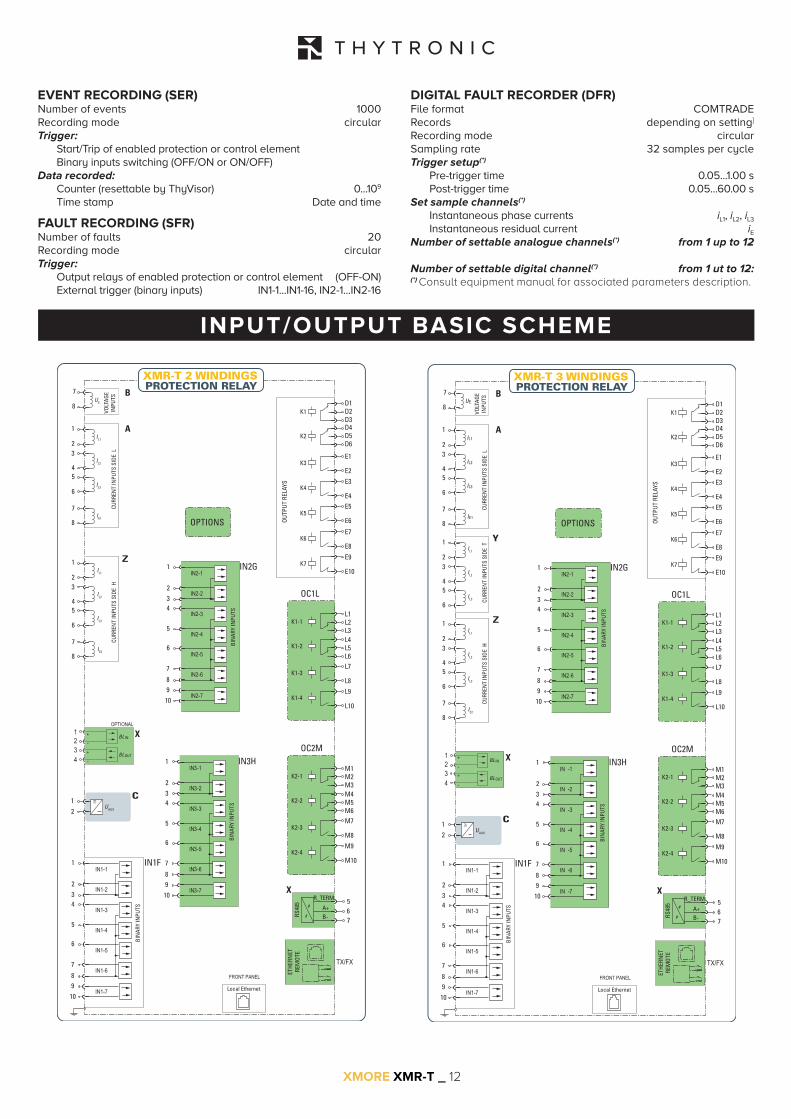
EVENT RECORDING (SER)Number of events 1000Recording mode circularTrigger:
Start/Trip of enabled protection or control element Binary inputs switching (OFF/ON or ON/OFF)
Data recorded: Counter (resettable by ThyVisor) 0...109
Time stamp Date and time
FAULT RECORDING (SFR)Number of faults 20Recording mode circularTrigger:
Output relays of enabled protection or control element (OFF-ON)External trigger (binary inputs) IN1-1...IN1-16, IN2-1...IN2-16
DIGITAL FAULT RECORDER (DFR)File format COMTRADERecords depending on setting]
Recording mode circularSampling rate 32 samples per cycleTrigger setup(*)
Pre-trigger time 0.05...1.00 sPost-trigger time 0.05...60.00 s
Set sample channels(*) Instantaneous phase currents iL1, iL2, iL3
Instantaneous residual current iENumber of settable analogue channels(*) from 1 up to 12
Number of settable digital channel(*) from 1 ut to 12:(*) Consult equipment manual for associated parameters description.
INPUT/OUTPUT BASIC SCHEME
UE
VOLT
AGE
INPU
TS
7
8
1IL1
IL2
IL3
IE1
23
45
6
7
8
Local Ethernet
RS48
5
67B-
A+
X
UAUX
1 ≅
2
C
X
B
A
IN2G
BIN
ARY
INPU
TS
1
234
5
6
7
8910
OUTP
UT R
ELAY
S E3
E4E5
E6
E7
E8
K1
K2
E1
E2K3
K4
K5
K6
K7
L1L2L3
L9
L10
OC1L
K1-1
L4L5L6
K1-2
L7
L8K1-3
K1-4
XMR-T 3 WINDINGS
OPTIONS
5R_TERM
D1D2D3D4D5D6
E9
E10
M1M2M3
M9
M10
OC2M
K2-1
M4M5M6
K2-2
M7
M8K2-3
K2-4
IN3H
BIN
ARY
INPU
TS
1
234
5
6
7
8910
CURR
ENT
INPU
TS S
IDE
L
BLOUT
BL IN
34
12
+
-
+
-
ETHE
RNET
REM
OTE
TX/FX
Z1
23
45
6
7
8
CURR
ENT
INPU
TS S
IDE
H
IN1F
BIN
ARY
INPU
TS
1
234
5
6
7
8910
FRONT PANEL
Y1
23
45
6
CURR
ENT
INPU
TS S
IDE
T
IL1
IL2
IL3
IE2
IL1
IL2
IL3
XMORE XMR-T _ 13
PROTECTIVE FUNCTIONS
IL1-H, IL2-H, IL3-H
IL1-T, IL2-T, IL3-T
87T
74TCS
IE-1
IE-2
26
Nota 2
Nota 3
50N/51N
87NHIZ.2
50N.2/51N.2
74CT
64REF.2
50N/51N
SIDE H or SIDE L or SIDE T
SIDE L
SIDE T
SIDE T
87NHIZ.1
50N.1/51N.1 64REF.1
SIDE H or SIDE L or SIDE T
I2/I14637 49 50/51 BF
IL1-L, IL2-L, IL3-L50N/51N
SIDE L
I2/I14637 49 50/51 BF
74CTI2/I14637 49 50/51 BF
74CT
IL1-H, IL2-H, IL3-H
IL1-T, IL2-T, IL3-T
87T
74TCS
IE-1
IE-2
26
Note 2
Note 3
50N/51N
87NHIZ.2
50N.2/51N.2
74CT
64REF.2
50N/51N
SIDE H or SIDE L or SIDE T
SIDE H
SIDE H
SIDE H
SIDE T
87NHIZ.1
50N.1/51N.1 64REF.1
SIDE H or SIDE L or SIDE T
I2/I14637 49 50/51 BF
IL1-L, IL2-L, IL3-L50N/51N
SIDE L
I2/I14637 49 50/51 BF
74CTI2/I14637 49 50/51 BF
74CT
G
Note 1: 59N alternative to 24, 27, 58, 81O and 81UNote 2: 50N.2/51N.2 alternative to 87NHIZ.2Note 3: 50N.1/51N.1 alternative to 87NHIZ.1
Note 159N
24 27 59 81O 81U
SIDE H or SIDE L or SIDE T
Nota 159N
24 27 59 81O 81U
SIDE H or SIDE L or SIDE T
XMR-T
XMR-T
86
86
XMORE XMR-T _ 14
SIDE L
IL1-H, IL2-H, IL3-H
IL1-T, IL2-T, IL3-T
87T
74TCS
IE-1
IE-2
26
Nota 2
Nota 3
50N/51N
87NHIZ.2
50N.2/51N.2
74CT
64REF.2
50N/51N
SIDE H or SIDE L or SIDE T
SIDE H
SIDE H
SIDE T SIDE T
87NHIZ.1
50N.1/51N.1 64REF.1
SIDE H or SIDE L or SIDE T
I2/I14637 49 50/51 BF
IL1-L, IL2-L, IL3-L50N/51N
SIDE L
I2/I14637 49 50/51 BF
74CTI2/I14637 49 50/51 BF
74CT
IL1-H, IL2-H, IL3-H
IL1-T, IL2-T, IL3-T
87T
74TCS
IE-1
IE-2
26
Nota 2
Nota 3
50N/51N
87NHIZ.2
50N.2/51N.2
74CT
64REF.2
50N/51N
SIDE H or SIDE L or SIDE T
SIDE H
SIDE T
87NHIZ.1
50N.1/51N.1 64REF.1
SIDE H or SIDE L or SIDE T
I2/I14637 49 50/51 BF
IL1-L, IL2-L, IL3-L50N/51N
SIDE L
I2/I14637 49 50/51 BF
74CTI2/I14637 49 50/51 BF
74CT
G
G
Nota 159N
24 27 59 81O 81U
SIDE H or SIDE L or SIDE T
Nota 159N
24 27 59 81O 81U
SIDE H or SIDE L or SIDE T
Note 1: 59N alternative to 24, 27, 58, 81O and 81UNote 2: 50N.2/51N.2 alternative to 87NHIZ.2Note 3: 50N.1/51N.1 alternative to 87NHIZ.1
XMR-T
XMR-T
86
86
86
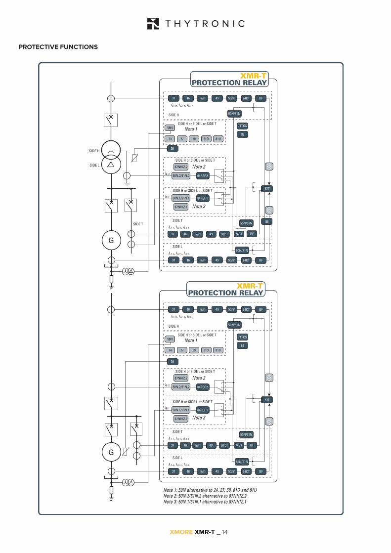
PROTECTIVE FUNCTIONS

XMORE XMR-T _ 15
IL1-H, IL2-H, IL3-H
IL1-T, IL2-T, IL3-T
87T
74TCS
IE-1
IE-2
Nota 2
Nota 3
50N/51N
87NHIZ.2
50N.2/51N.2
74CT
64REF.2
50N/51N
SIDE H or SIDE L or SIDE T
SIDE H
SIDE T
87NHIZ.1
50N.1/51N.1 64REF.1
SIDE H or SIDE L or SIDE T
I2/I14637 49 50/51 BF
IL1-L, IL2-L, IL3-L50N/51N
SIDE L
I2/I14637 49 50/51 BF
74CTI2/I14637 49 50/51 BF
74CT
IL1-H, IL2-H, IL3-H
IL1-T, IL2-T, IL3-T
87T
74TCS
IE-1
IE-2
26
Nota 2
Nota 3
50N/51N
87NHIZ.2
50N.2/51N.2
74CT
64REF.2
50N/51N
SIDE H or SIDE L or SIDE T
SIDE H
SIDE T
87NHIZ.1
50N.1/51N.1 64REF.1
SIDE H or SIDE L or SIDE T
I2/I14637 49 50/51 BF
IL1-L, IL2-L, IL3-L50N/51N
SIDE L
I2/I14637 49 50/51 BF
74CTI2/I14637 49 50/51 BF
74CT
SIDE L
SIDE H
Nota 159N
24 27 59 81O 81U
SIDE H or SIDE L or SIDE T
Nota 159N
24 27 59 81O 81U
SIDE H or SIDE L or SIDE T
Note 1: 59N alternative to 24, 27, 58, 81O and 81UNote 2: 50N.2/51N.2 alternative to 87NHIZ.2Note 3: 50N.1/51N.1 alternative to 87NHIZ.1
XMR-T
XMR-T
86
86
PROTECTIVE FUNCTIONS

XMORE XMR-T _ 16
IL1-H, IL2-H, IL3-H
IL1-T, IL2-T, IL3-T
87T
74TCS
IE-1
IE-2
Nota 2
Nota 3
50N/51N
87NHIZ.2
50N.2/51N.2
74CT
64REF.2
50N/51N
SIDE H or SIDE L or SIDE T
SIDE H
SIDE T
87NHIZ.1
50N.1/51N.1 64REF.1
SIDE H or SIDE L or SIDE T
I2/I14637 49 50/51 BF
IL1-L, IL2-L, IL3-L50N/51N
SIDE L
I2/I14637 49 50/51 BF
74CTI2/I14637 49 50/51 BF
74CT
IL1-H, IL2-H, IL3-H
IL1-T, IL2-T, IL3-T
87T
74TCS
IE-1
IE-2
26
Nota 2
Nota 3
50N/51N
87NHIZ.2
50N.2/51N.2
74CT
64REF.2
50N/51N
SIDE H or SIDE L or SIDE T
SIDE H
SIDE T
87NHIZ.1
50N.1/51N.1 64REF.1
SIDE H or SIDE L or SIDE T
I2/I14637 49 50/51 BF
IL1-L, IL2-L, IL3-L50N/51N
SIDE L
I2/I14637 49 50/51 BF
74CTI2/I14637 49 50/51 BF
74CT
SIDE L
SIDE H
Nota 159N
24 27 59 81O 81U
SIDE H or SIDE L or SIDE T
Nota 159N
24 27 59 81O 81U
SIDE H or SIDE L or SIDE T
Note 1: 59N alternative to 24, 27, 58, 81O and 81UNote 2: 50N.2/51N.2 alternative to 87NHIZ.2Note 3: 50N.1/51N.1 alternative to 87NHIZ.1
XMR-T
XMR-T
86
86
PROTECTIVE FUNCTIONS

XMORE XMR-T _ 17
L1 L2 L3
P1S1S2
P2
IE1
P1S1S2
P2
IE2
UE
A
B
a
b
P1S1S2
P2
IL1L
IL2L
IL3L
P1S1S2
P2
IL1T
IL2T
IL3T
P1
S1S2
P2
IL1H
IL2H
IL3H
Z5
Z6
A7
A8
Z7
Z8
Z3
Z4
Z1
B7
B8
Z2
A5
A6
A3
A4
A1
A2
Y5
Y6
Y3
Y4
Y1
Y2
26
87T
74TCS
Nota 2
Nota 3
50N/51N
87NHIZ.2
50N.2/51N.2
74CT
64REF.2
50N/51NSIDE L
87NHIZ.1
50N.1/51N.1 64REF.1
I2/I14637 49 50/51 BF
50N/51NSIDE T
I2/I14637 49 50/51 BF
74CTI2/I14637 49 50/51 BF
74CT
SIDE H
SIDE TSIDE L
SIDE H
Nota 159N
24 27 59 81O 81U
SIDE H or SIDE L or SIDE T
XMR-T
Note 1: 59N alternative to 24, 27, 58, 81O and 81UNote 2: 50N.2/51N.2 alternative to 87NHIZ.2Note 3: 50N.1/51N.1 alternative to 87NHIZ.1
Differential protection for three windings transformer
NOTE- Incoming currents to the protected transformer must match to the the reference current inputs of the relay, with current direction leaving the protected transformer must match current output from the current inputs of the relay.- Incoming currents in the reference terminals of of the relay current inputs are considered positive, the outgoing negative.- This convention applies to indicate the P1 CTs polarity toward the protected transformer.

XMORE XMR-T _ 18
DIMENSIONS
In relation to the evolution of materials and technical standards, THYTRONIC reserves the to modify without notice data and dimensions inside this data sheet
178
243
NETWORK
TX
X
23
1
178
243
Z
1
2
3
4
5
6
7
8
9
10
123
Y
A
B
26 193
220
246
11

www.thytronic.it
Headquarters:
20139 Milano IT
Piazza Mistral, 7
T. +39 02 57495701
F. +39 02 57403763
Factory:
35127 Padova IT
Z.I. Sud - Via dell’artigianato, 48
T. +39 0498947701
F. +39 0498701390
Proudly made in Italy by Thytronic S.p.A.
03-2021_Ed.07