Embed Size (px)
Citation preview

optoCONTROL CLS-K // Fiber optic sensors
More Precision

2
The optoCONTROL CLS-K series is an opto-electronic sensor solution where the electro-nics and the probe heads are coupled via op-tical fibers and therefore arranged separately.Due to numerous sheathings and probe heads, these optical fibers can be adapted to any application, therefore being flexible in use. Sophisticated, optical glass fibers stand out due to minimal installation dimensions and robust materials and are ideally suitable for harsh ambient conditions and high tempe-ratures.
The optoCONTROL CLS-K series includes a compact transmitter and receiver unit for in-frared light with integrated signal evaluation. The light transmission to the object and back is based on high-quality, optical glass fibers according to the principle of total reflection. The received light intensity is used for evalu-ation. The optoCONTROL CLS-K electronics offers variable amplification possibilities; the output
signal is available for downstream systems as a voltage or current signal. In addition to the-se, there are versions with electrically isolated optocoupler or relay outputs, displays, as well as a special version that provides temperature compensation and is protected to IP65.
These fiber optic sensors enable a wide va-riety of applications, from monitoring the presence of and recognizing the position of components in automatic assembly machi-nes, feeding systems, test and inspection applications, through to gap and web-edge detection.
High-speed processesDetection and inspection of small objects Integration in industrial environments

3
Reflex mode V arrangement in reflex mode
CLS-K Controller � Compact and robust, direct integration into machine � Ideal for monitoring of high-speed processes � High light intensity � Stable long-term behavior / transmission monitoring
Characteristics � Temperature resistance from -270°C to +2000°C � Flexible and highly flexible with flux � Cut and polished surfaces �Wavelength from 180nm (UV) to 3500nm (IR) � Customer-specific modification even for 1 single piece only
Probe heads for versatile applications
High-quality glass and special fibers for long-life operationMicro-Epsilon optical fibers feature high processing and trans-mission quality. Ground and polished end-faces ensure excellent optical integration with adapted sensors. These high-quality, optical glass fibers are extremely robust and ideally suitable for use in harsh ambient conditions.
Transmitted light mode
4 optoCONTROL CLS-KOptical fiber types
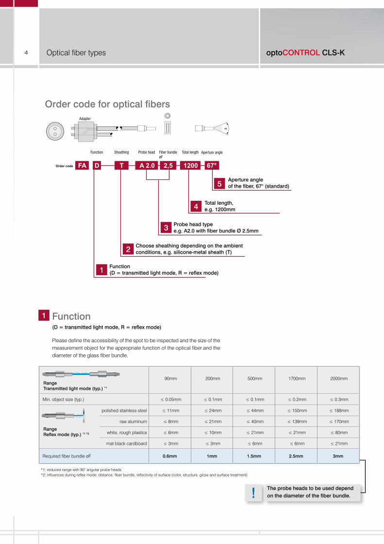
Order code for optical fibersAdapter
Function Sheathing Probe head Fiber bundleøF
Total length Aperture angle
D T A 2.0 2,5 1200 67°FAOrder code
1 2 3 4 5
a
Function(D = transmitted light mode, R = reflex mode)
Choose sheathing depending on the ambient conditions, e.g. silicone-metal sheath (T)
Probe head type e.g. A2.0 with fiber bundle Ø 2.5mm
Total length,e.g. 1200mm
Aperture angleof the fiber, 67° (standard)
Function(D = transmitted light mode, R = reflex mode)
Please define the accessibility of the spot to be inspected and the size of the measurement object for the appropriate function of the optical fiber and the diameter of the glass fiber bundle.
1
Range Transmitted light mode (typ.) *1
90mm 200mm 500mm 1700mm 2000mm
Min. object size (typ.) ≤ 0.05mm ≤ 0.1mm ≤ 0.1mm ≤ 0.2mm ≤ 0.3mm
Range Reflex mode (typ.) *1 *2
polished stainless steel ≤ 11mm ≤ 24mm ≤ 44mm ≤ 150mm ≤ 188mm
raw aluminum ≤ 8mm ≤ 21mm ≤ 40mm ≤ 139mm ≤ 170mm
white, rough plastics ≤ 6mm ≤ 10mm ≤ 21mm ≤ 21mm ≤ 80mm
mat black cardboard ≤ 3mm ≤ 3mm ≤ 6mm ≤ 6mm ≤ 21mm
Required fiber bundle øF 0.6mm 1mm 1.5mm 2.5mm 3mm
*1: reduced range with 90° angular probe heads *2: influences during reflex mode: distance, fiber bundle, reflectivity of surface (color, structure, gloss and surface treatment)
The probe heads to be used depend on the diameter of the fiber bundle.
1
2
3
4
5
!

5
Metal sheathFlexible brass wire-spiral-reinforced hose, chrome-plated 1)
Characteristics:- Flexible- Protection against mechanical stress- Temperature-stable to +300°C
T E M
1) Bending radius corresponds to three times the external diameter of the sheath.
2) Bending radius corresponds to twice the external diameter of the sheath.
Details about sheath diameters can be found in section 3.
PVC-metal sheathFlexible brass spiral-reinforced hosecoated with PVC sheathing 1)
Characteristics:- Flexible- Protection against mechanical stress such as pressure and tension - Temperature-stable from -20°C to +80°C
Z P On request
SheathingPlease determine the sheathing and the bonding of the optical fiber based on the prevailing environmental conditions and mechanical stress. Please contact us in case of high temperature applications or extreme, mechanical stress.
Silicone-metal sheathMetal wire-spiral-reinforced hose with glass-fiber braiding and silicone rubber sheathing 1)
Characteristics:- Very flexible, ideal for frequent bending- Highly resistant to bending, tension and torsion- Temperature-stable from -60°C to +180°C- Liquid-tight
VA stainless-steel sheathFlexible stainless steel wire-spiral-reinforced hose 1)
Characteristics:- Flexible- Protection against mechanical stress- Temperature-stable to +400°C- Stainless, typical for the food industry
PVC special sheathPlastic hose 2)
Characteristics:- For rigid installation- Small sheath diameter- Temperature-stable to 60°C
BOA special sheathCorrugated tube with stainless steel braiding 2)
Characteristics:- Protection against mechanical stress- Ideal for drag-chain applications- Temperature-stable from -270°C to +600°C
2
Special modelsOptical fibers with increased vibration protection - VS optionOptical fibers can be manufactured with increased vibration protection for use with mechanical loads such as shock, accele-ration, and movement. This special treatment minimizes friction between fibers and reduces shocks. The fibers are embedded into a gel cushion.
Special modelsOptical fibers with special bonding for high temperaturesStandard bonding is suitable for maximum temperatures up to 80°C. Special adhesi-ves allow for temperatures of up to 250°C and even 400°C. These higher temperature ranges require the use of Type E stainless steel sheathing. With quartz and sapphire fibers and appropriate adhesive, special optical fibers for use in environments up to 2000°C can be produced.
!
6
D
ø J
ø A
ø F B2
ø E
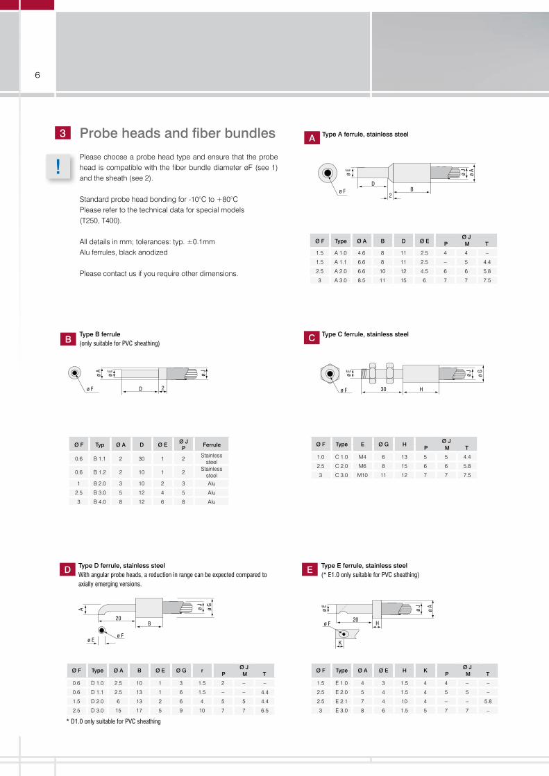
Ø F Type Ø A B D Ø E Ø J
P M T
1.5 A 1.0 4.6 8 11 2.5 4 4 –
1.5 A 1.1 6.6 8 11 2.5 – 5 4.4
2.5 A 2.0 6.6 10 12 4.5 6 6 5.8
3 A 3.0 8.5 11 15 6 7 7 7.5
ø J
ø A
ø E
D 2ø F
BType B ferrule(only suitable for PVC sheathing)
Ø F Typ Ø A D Ø E Ø J P
Ferrule
0.6 B 1.1 2 30 1 2 Stainless
steel
0.6 B 1.2 2 10 1 2 Stainless
steel 1 B 2.0 3 10 2 3 Alu
2.5 B 3.0 5 12 4 5 Alu
3 B 4.0 8 12 6 8 Alu
ø J
ø G
30 Hø F
ø E
C Type C ferrule, stainless steel
Ø F Type E Ø G H Ø JP M T
1.0 C 1.0 M4 6 13 5 5 4.4
2.5 C 2.0 M6 8 15 6 6 5.8
3 C 3.0 M10 11 12 7 7 7.5
A
20
ø J
ø G
ø Fø E
B
D
Ø F Type Ø A B Ø E Ø G r Ø JP M T
0.6 D 1.0 2.5 10 1 3 1.5 2 – –
0.6 D 1.1 2.5 13 1 6 1.5 – – 4.4
1.5 D 2.0 6 13 2 6 4 5 5 4.4
2.5 D 3.0 15 17 5 9 10 7 7 6.5
* D1.0 only suitable for PVC sheathing
Type D ferrule, stainless steelWith angular probe heads, a reduction in range can be expected compared to axially emerging versions.
ø F
ø J
ø A
ø E
20H
K
E Type E ferrule, stainless steel(* E1.0 only suitable for PVC sheathing)
Ø F Type Ø A Ø E H K Ø JP M T
1.5 E 1.0 4 3 1.5 4 4 – –
2.5 E 2.0 5 4 1.5 4 5 5 –
2.5 E 2.1 7 4 10 4 – – 5.8
3 E 3.0 8 6 1.5 5 7 7 –
A Type A ferrule, stainless steelProbe heads and fiber bundles
Please choose a probe head type and ensure that the probe head is compatible with the fiber bundle diameter øF (see 1) and the sheath (see 2).
Standard probe head bonding for -10°C to +80°CPlease refer to the technical data for special models (T250, T400).
All details in mm; tolerances: typ. ±0.1mmAlu ferrules, black anodized
Please contact us if you require other dimensions.
3
!

7
ø J
ø A
ø E
HD
ø F
M
Ø F Type Ø A D Ø E H Ø J FerruleM T
0.6 M 1.1 6 30 1 10 5 4.4 Stainless steel
0.6 M 1.2 6 10 1 10 5 4.4 Stainless steel
1 M 2.0 6 10 2 10 5 4.4 Alu
2.5 M 3.0 7 12 4 12 6 5.8 Alu
3.5 M 4.0 9 12 6 12 7 7.5 Alu
Larger fiber cross-sections are possible
Type M ferrule, aluminum / stainless steel
ø J
ø E
G
D
2 Position
F
ø J
F B
A
5 5
C
D
G
ø 3,2
R Type R ferrule, aluminum P Type P ferrule, aluminum
Type D Ø E F G max.Ø J
P M T
R 1.0* 25 4 3 0.5 3 – –
R 1.1 30 7 3 0.5 6 6 5.8
R 2.0 25 7 6 1 6 6 5.8**
R 2.1 30 10 6 1 – 7 7.5
* R1.0 and R2.0 only suitable for PVC sheathing** at 6x1mm², can be made to a length of 1200
Type A B C D F GØ J
P M T
P 1.0 8 15 9 25 3 0.1 4 5 4.4
P 2.1 8 17 11 30 6 0.3 4 6 6.5
P 3.1 12 17 11 30 10 0.5 6 6 6.5
ø J
ø A
ø F
K
ø E
20H
2 Guidance bore
F
Ø F Type Ø A Ø E H KØ J
P M T
1.5 F 1.0 8 6 9 3 5 5 5.8
2.5 F 2.0 10 8 10 4 6 6 6.5
3 F 3.0 12 10 10 5 7 7 7.5
Type F ferrule, stainless steelWith angular probe heads, a reduction in range can be expected compared to axially emerging versions.
ø J
ø A
non-bendable part 10
ø F
ø E
100
Rmin=8
H
O Type O ferrule, bendable to a certain extentWith angular probe heads, a reduction in range can be expected compared to axially emerging versions.
Ø F Type Ø A Ø E H Ø J
P M T
0.6 O 1.0 2 1 10 2 – –
0.6 O 1.1 7 1 20 – 5 4.4
1 O 2.0 3 1.3 10 3 – –
1 O 2.1 7 1.3 20 – 5 4.4
ø J
G
F E
A
D
C
B
ø 3,2
Q Type Q, aluminumAlso available in stainless steel
Type A B C D E F G Ø J
Q1 12 25 9 15 15 5 0.5Q2 12 30 14 20 20 10 0.3
depe
nds
onfib
er c
ross
-sec
tionQ3 12 35 24 25 30 18 0.3
Q4 12 55 34 40 40 28 0.2Q5 12 55 44 40 50 38 0.15Q6 12 55 54 40 60 48 0.15Q7 16 75 64 60 70 58 *Q8 16 75 74 60 80 68 *Q9 20 90 84 75 90 78 *Q10 20 90 94 75 100 88 *
FxG max. 9.62mm²F=3.5 mm as special modelQ7 to Q10 only available as FAR special model

8
Technical data // Optical fibers
Length Standard lengths: 600, 1200, 1800 and 2400mm, up to 30m on request
Aperture angle
Standard fiber 67° (NA 0.56)1)
Special fibers on request
22° (NA 0.21/glass fibers)80° (NA 0.64/glass fibers)120° (NA 0.86/glass fibers)25° (NA 0.22/UV-VIS and VIS-IR quartz fibers)14° (NA 0.12/UV-VIS and VIS-IR quartz fibers)
Material Optical glass; quartz glass or sapphire glass on request
Dielectric strength 50kV/m with PVC protective sheath
Probe head Temperature range Fiber bonding
Standard -10°C up to +80°C
T250 -40°C up to +250°C
T400 -40°C up to +400°C
T600 special model 0°C up to +600°C
T2000 special model 0°C up to +2000°C
Permissible temperature range with sheathing that has appropriate fiber bonding
PVC (Type P / Type Z) -20°C up to +80°C
Metal (type M) -40°C up to +300°C
Metal with special bonding (Type E) -40°C up to +400°C
Metal/silicone (Type T) -40°C up to +180°C
Fiber transmission Different types for wavelengths from UV 180nm to IR 3500nm. We can provide the most suitable solution depending on your requirements. Transmission curves on request.
Vibration protection Increased vibration protection (VS option)
1) Fiber transmission standard fiber 390 - 1390nm
Standard lengths are: 600*, 1200*, 1800 and 2400mm.*Bearing typesTyp. length tolerance: ±4%Cable lengths of up to 30m can be supplied on request.
Standard aperture angle 67°
67°
4 Length:
Extensions / feed-throughFor extension or feed-through of the optical fibers please use the Type LV ferrule.
5 Aperture angle
JØ
60 (mounted)
40
L
M18
LV
Fiber bundle Ø PØ J M T L
(3mm)/ channel 12 13 13.5 variable
Type LV ferruleFiber optic extension / feed-through
Pressure-proof feed-through
Housing feed-through
Adapter fiber-optic cable FA on FA
Available on request

9
Optical fiber functions
Application instructions on selecting the appropriate function.
Reflex mode � Max. measurement distance 180mm � Easy and fast installation � Detection of smallest objects from 0.2mm � Intensity evaluation to determine position, gloss level, gray value, presence � Ideal for part recognition, counting tasks, presence monitoring
Special types for multiple reflex modeTransmission and receiving fibers are, statistically mixed, guided in two or more separated optical fibers. Therefore, several positions can be detected using only one sensor.
Special types for multiple transmitted light modeThe light path of the axially opposing probe head ferrules is interrupted or damped by one or more objects.
Available on request
Available on request
Reflex mode V arrangement � Max. measurement distance 1000mm (with reflecting surfaces) � Easy adjustment due to mounting accessories � Very exact positioning of the switching point � Objects generate highest intensity on the intersection � Immune to dust and particles in the beam path
Transmitted light mode � Large distance between receiving and transmission unit up to 2000mm � Objects are detected by interruption of light beam � Arbitrary point of light transmission � High reproducibility of the object transmission � Intensity measurement with semi-transparent objects � Ideal for part recognition, counting tasks, edge detection, presence monitoring
!

10
Features: �Working distances from 8mm to 200mm � Scratch-resistant glass lens � Robust aluminum housing (black anodized) � Bundling to a small light spot � Increasing the range � Minimum color change when the distance is altered � High luminous efficiency � Special designs according to customer requirements � Recognition of highly absorbent objects
Mountable lenses for optical fibers KL-xx/xx series
- Focusing of fiber optic sensors
- Improving the efficiency of the application
- Many possible applications
Focus lenses for special applications
Available on request

11
- Focusing of fiber optic sensors
- Improving the efficiency of the application
- Many possible applications
Detection and inspection of small objects
Edge detection of PCBs
Counting tasks with bulk material
Presence check of components
Packaging control of blisters
Inspection tasks with high ambient temperatures

12
Features: � Scanning distance up to 180mm* � Range of up to 2m* * depending on the fiber bundle diameter
� Switching output: NPN, PNP, optocoupler and relay � Adjustable drop-out delay 5-100ms (optional)
Applications: � Powerful infrared emitter � Test & measurement tasks � Position recognition of small parts � Position and assembly monitoring on automatic assembly machines and feeding systems � Presence monitoring � Checking length and diameter
Advantages: � Precise and reliable object detection � Low drift due to transmission monitoring, making it particularly suitable for measuring tasks � High switching frequency and short response time � Sensor monitoring via analog signal � Stable long-term behavior by monitoring and regulating the emission of the transmitter diode � High light power in the non-visible infrared range
Response time ≤ 120µs
Switching frequency ≤ 4kHz
Analog Analog output 0.1 - 5VDC
optoCONTROL CLS-KTest amplifiers for common tasks
13
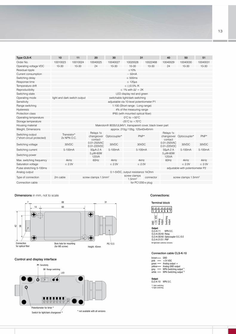
Type CLS-K 10 11 20 30 31 40 50 51
Order No. 10010023 10010024 10040025 10040027 10020028 10022468 10040029 10040030 10040031 Operating voltage VDC 10-30 10-30 24 10-30 10-30 10-30 24 10-30 10-30 Residual ripple ≤10%Current consumption ~ 50mA Switching delay ≤ 500msResponse time ≤ 120μs Temperature drift ≤ (-)0.5% /K Reproducibility ≤ 1% with ∆∂ = 2K Switching state LED display red and greenOperating mode light and dark switch output switchable light/dark switchingSensitivity adjustable via 10-level potentiometer P1Range switching 1:100 (Short range : Long range)Hysteresis 4% of the measuring rangeProtection class IP65 (with mounted optical fiber)Operating temperature 0°C to +50°C Storage temperature -25°C to +70°C Housing material Makrolon® 8035/UL94V1, transparent cover, black lower part Weight, Dimensions approx. 215g / 135g, 125x42x45mm
Switching output (*short-circuit protected)
Transistor* 2x NPN O.C.
Relays 1x changeover
contact Optocoupler* PNP*
Relays 1x changeover
contact Optocoupler* PNP*
Switching voltage 30VDC 0.01-250VAC 0.01-220VDC
30VDC 30VDC 0.01-250VAC 0.01-220VDC
30VDC 30VDC
Switching current 5-100mA 50μA-2 A 5-100mA 5-100mA 50μA-2 A 5-100mA 5-100mA
Switching power5 μW-60W
125VA5 μW-60W
125VA
Max. switching frequency 4kHz 60Hz 4kHz 4kHz 60Hz 4kHz 4kHz Saturation voltage ≤ 2.0V ≤ 2.0V ≤ 2.0V ≤ 2.0V ≤ 2.0VPulse stretching 5-100ms adjustable with potentiometer P2Analog output 0.1-5VDC, output resistance 1kOhm
Type of connection 2m cable screw clamps 1.5mm2 screw clamps 1.5mm2
connector screw clamps 1.5mm2
Connection cable for PC1200-x plug
Dimensions in mm, not to scale
Control and display interface
7 88
60
31
14
30
PG 13.5Connection for optical fiber
Bore hole for mounting(for M5 screw)
42
Height: 45mm
Connections:
Terminal block
*1*2
dark switching light switching
brown GND pink +24 VDC green Analog output +yellow Analog GND outputgrey NPN-Switching outputwhite NPN-Switching output
*1
*2
1 2 3 4 5 6 7
Switc
hing
ou
tput
Anal
og
outp
ut
+24
VDC
GND
Output:CLS-K-11: NPN O.C.CLS-K-20/40: RelayCLS-K-30/50: Optocoupler O.C./O.E CLS-K-31/51: PNP
Output:CLS-K-10: NPN O.C.
All light/dark switches versions
Connection cable CLS-K-10
Switch for light/dark changeover *
P1 Sensitivity
Range switchingS1
LED
* not available with all versions
Potentiometer for timer *

14
Features: � Scanning distance up to 180mm* � Range up to 2m*
* depending on the fiber bundle diameter
� Supply 12-30VDC � NPN switching output � Stable long-term behavior by monitoring and regulating the emission of the transmitter diode
Applications: � Powerful infrared emitter � Test & measurement tasks � Checking length and diameter � Production monitoring via analog output and display � Assembly control � Indirect displacement measurement via optical fiber with cross-section converter
Advantages: � Low drift by transmission monitoring � Fast response time � Sensor monitoring via analog signal � High light power in the non-visible infrared range
Scaling of analog output
5 V / 10 mA
0 V / 0 mA
Analog output
Switch S2 in position »1«
10 V / 20 mA
0 V / mA
Analog output
Switch S2 in position »2«
Offset
The CLS-K-61/63 amplifier offers the possibility to scale the important signal range over the entire analog range. This enables to increase the sensitivity in a certain range, e.g. for the detection of small objects.
Analog Analog output 0 - 10VDC; 0 - 20mA; 4 - 20mA
Response time ≤ 120µs
Switching frequency ≤ 4kHz
Analog display
optoCONTROL CLS-K-6Universal test amplifiers for versatile integration possibilities
15
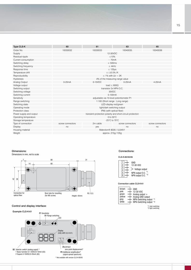
Dimensions:Dimensions in mm, not to scale
Type CLS-K 60 61 63 65
Order No. 10030032 10030033 10040035 10040036Supply 12-30VDCResidual ripple ≤10%Current consumption ~ 70mA Switching delay ≤ 500ms Switching frequency ≤ 4kHz Response time ≤ 120μs Temperature drift ≤ (-)0.5% /K Reproducibility ≤ 1% with ∆∂ = 2K Hysteresis 4% of the measuring range valueAnalog Output 0-20mA 0-10VDC 0-20mA 4-20mAVoltage output load ≤ 600ΩSwitching output transistor 2x NPN O.C.Switching voltage 30VDCSwitching current 5-100mASensitivity adjustable via 10-level potentiometer P1Range switching 1:100 (Short range : Long range)Switching state LED-display red/greenOperating mode light/dark switching outputProtection class IP65 (with optical fiber)Power supply and output transient-protection polarity and short-circuit protectionOperating temperature 0 to 50°CStorage temperature -25°C to 70°CType of connection screw connectors 2m cable screw connectors screw connectorsDisplay no yes no noHousing material Makrolon® 8035 / UL94V1Weight approx. 215g / 135g
Control and display interface:
7 88
60
31
14
30
PG 13.5Connection for optical fiber
Bore hole for mounting(for M5 screw)
42
Height: 45mm
2 1
P2 Additional amplification* (signal spread spectrum)
P3 OFFSET zero point displacement*
P1 Sensitivity S1 Range switching
S2 Selector switch (analog ouput) * 1 Basic function 0.1-5VDC/0-10mA (63) 2 Ouputs 0-10VDC/0-20mA (63)
Example CLS-K-61
LED
Display (only with CLS-K-61)
* Not available with version CLS-K-60/65
Connections:
brown pink greenyellowgreywhite
GND12-30 VDCAnalog output +Analog GND outputNPN-Switching outputNPN-Switching output
123456
GND12-30 VDC Voltage output
NPN output O.C.NPN output O.C.
CLS-K-60/63/65 Connection cable CLS-K-61
*1
*2
*1
*2
*1*2
dark switchinglight switching
brown pink greenyellowgreywhite
GND12-30 VDCAnalog output +Analog GND outputNPN-Switching outputNPN-Switching output
123456
GND12-30 VDC Voltage output
NPN output O.C.NPN output O.C.
CLS-K-60/63/65 Connection cable CLS-K-61
*1
*2
*1
*2
*1*2
dark switchinglight switching
Mod
ifica
tions
rese
rved
/ Y9
7613
78-C
0210
69G
KE
MICRO-EPSILON Eltrotec GmbH
Manfred-Wörner-Str. 101 · 73037 Göppingen · Germany
Tel. +49 (0)7161 98872-300 · Fax+49 (0)7161 98872-303
[email protected] · www.micro-epsilon.com
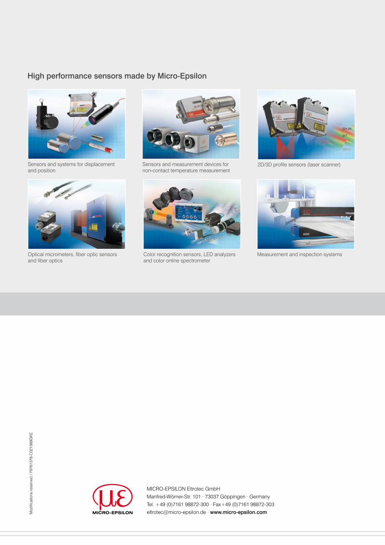
High performance sensors made by Micro-Epsilon
Sensors and systems for displacement and position
Sensors and measurement devices for non-contact temperature measurement
Measurement and inspection systemsOptical micrometers, fiber optic sensors and fiber optics
Color recognition sensors, LED analyzers and color online spectrometer
2D/3D profile sensors (laser scanner)