Embed Size (px)
Citation preview

While not strictly a compendium on baluns, W2FMI doesreview the amateur literature, both fact and fanciful, on thesubject. He also presents the results of his experimentsplus workable designs that we can build.
More On The 1:1 BalunBY JERRY SEVICK'. W2FMI
Fig, 1- lIIustration of/he various currents at thefeed point a/a dipole, I, is the dipole curren/and /2 is the inverted L (imbalance) current.
I,-
- ,I ShieldIIIIII
__J
A,
0-)v,
1I
II + 121~III1111,,,,,
<, I
«
~,,,IIIII..._---- - -
under the dipole, a large change in the VSWRtook place. This meant the inverteo-L modewas appreciable.
It should also be pointed out that the direction of '2, the imbalance current, can dependupon the side on which the coaxial cable is outof the ground plane of the dipole. For example, if it comes down under the right side in fig.1 (that is, the angle between the horizontal armand the coax is less than 90 degrees on theright side and more than 90 degrees on theleft side), then the di rection of '2can be reversed by the imbalance in the induced currents on the outside of the braid By the sametoken, by having the coaxial cable come downon the other side, the value of I., is only increased in magnitude.
Feeding a Yagi beam Without a wen-oesigned 1:1 balun, however. is a different matter . Since most Yagi designs use shunt-feeding (usually by hair-pin matching networks) inorder to raise the input impedance close to 50ohms, the effective spacing Is) is greatly increased. Furthermore, the center of the drivenelement is actually grounded , Thus, connect-
to antennas such as dipoles. invened Vees.and Vagi beams wtlich favor a balanced feed.In esserc..\ they prefer a source of power theterminals of which are balanced (voltagesbeing equal and opposite) with respect to actual ground or to the virtual ground whichbisects the center of the antenna. The question frequently asked is whether a 1:1 balun isreally needed.
To illustrate the problem involved and 10give a basis lor my suggestions, I refer you tofig, 1. Here we have, at the feed po int of thedipole. two equal and opposi te transmissionline currents which have two componentseach-II and 12- Also shown is the spacing (s)between the center conductor and the outsidebraid. rbeo-eucauv. a balanced antenna witha balanced feed would have a ground (zeropotential) plane bisecting this spacing.However, since a coax-feed is unbalancedand the outer braid is also connected toground at some point. an imbalance exists atthe feed point. giving rise to two antennamodes, One is with 11 giving a dipole mode,and the other is with 12 giving an mvertec-t,mode.
If the spacing (s) is inc reased, the imbalance at the feed po int becomes greater, giving rise to more current on the outer braid anda larger unbalance of currents on the antenna's arms, Several steps can be taken to eliminate or minimize the undesirable inverted-Lmode (eliminate or minimize '2), The obviousone is to use a well-designed balun , which notonly provides a balanced feed, but also minimizes (by its choking reactance) I., il the coaxial cable does not lie in the ground plane whichbisects the center of the dipole, The other stepis to ground the coaxial cable at a quarterwave (or odd-multiple thereof) from the feedpoint. This discourages the inverteo-L mode,since il wants to see a high impedance at theselengths instead of the low impedance of aground connect ion.
Experiments with baluns were conductedon a 20 meter half-wave dipole at a height of0.17 wavelength, which gave a resonant impedance of 50 ohms, VSWR curves were compared under various conditions. When thecoaxial cable was in the g round plane of theantenna (that is. perpendicular to the axis ofthe antema). the VSWR curves were identicalwith or without a well-designed balun no malter where the outer braid was grounded. Onlywhen the coaxial cable was out of the groundplanewasa significant difference noted. Whenthe cable dropped down at a 45 degree angle
When To Use A Balun
Baluns have taken on a more significant rolein the past few decades with the advent ofsolid-state transceivers ano Class B linearamplifiers, which have unbalanced outputsthat is, the voltage on the center conductor oftheir output chassis connectors varies (plusand minus) with respect 10 ground, In manycases coaxial cables are used as the transmission lines from these unbalanced outputs
Mymost recent CQ article entitled ' MoreOn The 4:1 Balun"! presented some new 4 .1designs as well as an evaluation of the designswhich have appeared in our amateur radio literature over the years. It you read the article.you saw that I was very critical of the information made available to amateurs, In fact, it wasshown that a very poor design was convertedinto a "peerless" design by making three simple changes, The number of bifilar turns waschanged from 10 to 14, the c ross-sectionalarea of the toroid was doubled by stacking twotogether, and the wires were covered withTeflon tubing. resulting in the optimum characteristic impedance of the coiled transmission line. These changes made very significant improvements in both the low- andhigh-frequency responses of the 4 1 balun .
This article can be said to be a complemenlto the 4: 1 balun article. In this case it treats themuch more popular 1.1 balun . It begins withmy view on when to use a balun. Even thoughmuch of what has been written here is takenfrom my Summer 1992 article in Communications Quarterly." it is presented again here,since some of you don't subscribe to that jou rnal. As before, highlights are also g iven onwhat has been available in the professionaland amateur radio literature on the understanding and design of the 1:1 balun.
This information is then followed by some ofmy latest designs. Of special interest might bethe one I call the "economy' model. Economy,in this case, refers 10 economy in labor. I hopesome of lhese baluns are constructed andcompared with the ' expensive' (in labor) models also described in this article.
The article finally closes with a short summary of the significant points brought forth inthis essay. As will be seen (again), the information available to radio amateurs has beensorely lacking over the past 25 years (at least) I
"32 Granvi/Ie Way, Basking Ridge, NJ 07920
26 • ca • April 1994 Say You Saw n In CO

I$289 (plus S & H ) IHigh Sierra Antennas
P.O. Box 2389Nevada City, CA
95959, USATel: (916) 273-3415Fax: (916) 273-7561
Write for brochure
HF Mobile Antenna
Based on \V6AAQ's famousD K3(" s c r ew d ri v e r")antenna••.with some imprrrvements.
1~"9tk...
lllm@OO ®nrn:~~1&
High perJonnance. provendesign. Heavy duty construction . All machined pans-stainless steel hardware!
Continuous coverage from305MHz to 30MHz. All without setting foot outside yourcar, motorhome, or RV!
Exclusive "decoupler"eliminates need for contactfingers.. .very reliable!
Built-in matching device ,Low SWR overentire range,No antenna tuner required !
Rainshield & base mounthardware kit included!
,
•
,
,
•
(01
(AI
,
•,
v,
v,
,
,
Fig. 2- Two versions of the 1.- 1 balun: (A) TheGuanella balun and the basic building block:
(8) The Ruthroff balun as originally drawn.
a half-wave dipole. Whi le at North Caroli naState Univers ity, he conducted an experimental investigation of pattern distortion without abalun at 1.6 GHz in an RF anechoic chamber(wh ich simulates ' tree space") Briefly, hisresults showed that with a balun (a bazookatype), the rad iation pattern compared veryfavorably with the classic °figure-eight" pattern. Without the balun, the rad iation patternwas severely distorted.
Even thou gh the author expressed difficulty in obtaining accurate measurements at thisvery high frequency, l have a question regarding the validity of performing the experiment
Photo A- The two basic forms of the I.- I balun which first appeared in the professiOnal literature. The rwo-conductor Guanella balun is on me left and the three-conductor Ruthroff balun
is on the right.
ing the outer braid (which is grounded at somepoint) to one of the input terminals creates alarge imbalance and hence a real need for abalun . An interesting solution, which wouldeliminate the matching network, is to use astep-down balun designed to match 50 ohmcable d irectly to the lower balanced-impedance of the driven elemenl,s
In summary, if one concurs with the theo retical model of fig. 1, my experiments perfo rmedon 20 meters , and the reports from radio amateurs using dipoles and inverted Vees withoutbaluns. then it appears that 1:1beluns are really needed for (a) Vag i beam antennas wheresevere pattern d istortion can take place without one and (b) d ipoles and inverted Vees thathave the coa xial cable feed lines out of theground plane that bisects the antennas or thatare unbalanced by their p roximity to manmade or natural structures. In general, theneed for a balun is not so critical with dipolesand inverted Vees (especially on 40, 80, and160 meters) because the diameter of the coaxia� cable connector at the feed point is muchsmaller than the wavelength.
If my model-which assumes that a part ofthe problem when feed ing balanced antennaswith coaxial cable is related to the size of mespa cing (s), shown in fig. l -is correc t, thenthe possibility exists lor using ununs for matching into balanced antennas with impedancesother than 50 ohms and with small values 01s.For example, half-wave dipoles at a height 01about a half-wave, quads and center-fed 3("1wave dipoles which all have impedancesclose to roo on-os.cccrc vervweu be matchedto50ohmcable by a2: 1unun.· As was srown.they are considerably easier to construct than2:1 beluns.e Furthermore, Genaille6 has recently shown considerable success in usingununs in this kind of application.
In closing this section I would like to comment on an artic le published by Eggers ,WA9NEW,7concerning the use of a balun with
!=:RV You SAW It In CO
CIRCLE 50 ON READER SERVICE CARD
Apri ll994 • CO • 27

Photo B- Two versions of tumne design: on the left, the 1:1 balun that has appeared in theamateur radio literature; on the right, a 1:1 balun that has been readify availabfe in kit form from
Amidon Associates, Inc.
•
In The Professional Literature
As I noted in a recent CQ artcie.e there areactually only two significant articles in the professional literature that provide the fundamental principles upon which the theory anddesign of this class of transformers are based .It can be said that succeeding investigatorsonly really extended the works of the authorsof these two articles.
The first presentation on broadband matching transformers using transmission lines wasgiven by Guanella in 1944.8 He coi led transmission lines form ing a choke such that onlytransmission-line currents were allowed to flowno matter where a ground was connected tothe load. His single, coiled transmission lineresulted in a 1:1 ba lun, It is shown on the leftin fig . 2(Aj, Prior to th is RF ba luns wereachieved by the use of quarter- and half-wavetransm ission lines , and as a result, had narrowbandwidths. Guanella then demonstratedbroadband baluns with impedance transformations of 1:n2where n is the number of transmission lines he connected in a series-parallel arrangement.
Several important points should be maderegarding Guanella's 1:1 balun shown in fig.2(A) With suffic ient choking reactance so thatthe output is isolated from the input and onlytransmission-line currents flow, by groundingterminal 5 (actually or virtually like the centerof a dipole), term inal 4 becomes +V1/2 and terminal2 becomes -V 1/2, resultinq in a ba lancedoutput. This type of balun has lately beencalled a "current" or "choke" ba lun, A significant feature of this model is that a potentialgrad ient at -V1/2 exists along the length of thetransmission line This gradient, wh ich existson both conductors. accounts for practicallyall of the loss in these transformers, since theloss-mechanism is voltaqe-oepenoent (a dielectr ic-type loss). All transmission-line transformers have some sort of voltage gradientalong their transmission lines and are thussubject to the same type of losses. Furthermore, the theory and loss-mechanism arethe same whether the transmission lines are
of these devices has not always been positive.In fact. in some cases just the opposite hasbeen true.
a-berencsc
•
•
,
(A)
(8),
•
,v,
Fig, 3--- (A) A pictorial of Turret's 1: 1balun,and(B) a schematic of his balun.
Highlights of SignificantArticles on 1:1 Baluns
A-unbalanced
in the first p lace , From the photograph in thearticle it appears that conventional coaxialcable and connectors were used in the experiment. If we assume an effective diameter of0.375 inches for these components, then scaling up 10 3.5 MHz (457.14 fold) resul ts in acoaxial cable with a diameter of 14.28 feet! Iam quite sure that the large spacing (s) of 7.14feet wo uld bring about a noticeable imbalance, resu lting in appreciable pattern distortion even at35 MHz.
Although there have been many articles published in the professional and amateur literature, I have selected a few that I thought hadthe most impact on 1:1 baluns for amateurradio use , As you will see, even though I consider some of the amateur articles significant,their impact upon the use and understanding
1112 GRANDV1EW STR EETSCRANTON, PEN NSYLVA NIA 18509
PHONE (717) 343·2124
ICOM1C-728 HF Xcvr./Geo. Gov,Rcvr ,., , $899.00IC-735 HF Xcvr.lGeo. ccv Rcvr , , 1054,00Ic·mA HF Xcvf.lGeo. Gov. Rcvr, ,. ,•. ".,..,.".,.. ,1469,00PS·55 AC Powet Si.pply 226.00AT·l50 HFAu10malic Antenna TUIIef 439.00SM-8 Desk Microphone 111 .00SP·7 Base Stalioo External Speaker 68.00sp·l0 Mobile External Speaket , 43,00SP·2(1 Base Stalion Ext. Spkr. W!AudioFilters 162.00IC-Rl CorTm.rlk:alioos Receivet 469.00lC-R700J Communicalioos Receiver 1249.00IC-R71oo Ccmmunicatiorts Receiver 1319.001C-228H 2-Melet, FM,45Wall Xcif 369.001C-229H 2-Melet, FM.50 Wall Xcvr. 389.001C-323OH 2·Mtr./44o-MHz., FM, 45W!35W " 649.001e-2GAT 2-Mb'., FM.Homtleld W!lh T-T ,294.00IC4GAT 44Q.MHz.,FM, Handheld With T·T 294.001C-2GXAT 2·Meter, FM,Mini Handheld WIT·T 294.00IC-2SRA 2-Mb'./5O-0C6·MHz.•FM, Mini H·t-VT·T 499.00le·W2A 2-Mtr'/44l).MHz" FM, Mini H·HWrr·T " 474.00BP·4 Ballery Case ".".. 20,00BP·5 10,8 VOC, 425 mAH" N~Cad Batt Pad!. 73.00BP·7 13,2VDC. 425 mAH" Ni-Cad Batt Pad!. 87.00BP·8 8.4 VOC, sec mAH.• Ni-Gad Ball. Pad< 87.00CM·96 8.4 VDC, 1200 mAH" N~Cad Batt Pack 99.00BP·8J 7,2VOC.BOO mAH" Ni-Cad Batt. Pack 65.00BP·84 7,2VOC, l roJ mAH" Ni-Gad Batt. Pad< "".. 87.00BP·OO Ballery Case 2O.ooBP·l30A Batlery Case ,"'" 21.00BP·157A 7,2VDC, 900 mAH. , Ni-CadBatt. Pack 54.00BP·l60 7.2VDC, 700 mAH" Ni-Gad Batt Pad< 43.00BC·35U Desk10p Charger: BP·2, 5,7, 8,96 95.00BC·72A Desktop Chg,; 8p·81, 82, 8J, 84, 85,Int. .104,00BC·79NAD-28 Dsklp. Chg,; 8p-132A, lS7A, 160 .13100CP-l1 Cigarette Ughtet Cable W/N oise Fillet 29.00CP·12 Cigarette lightet Cable W/Ndse Filler 2100CP-13 Cigarette Lighter Cable W/Noise Filler 2200HM·46 Speaket/Micropllone ".." " 40,00HM·54 Speaket/Microphone " """ 55,00HM·65 Speaket/Microphone For IC·2SRMV2A ,42,00HM·7Q Speaker!Microphone For IC·2SRMV2A '42,00HS·51 aeeeset PIT &VOX 67,00HS·60 Headset PIT &VOX, For IC·2SRMY2A 76,00
BENCHERBY·l Iambic Paddles, Black Base $84.95BY·2 Iambic Paddles. Quorne Base 79,95ZA·1A 1:1Balun, 3,5 ToJO-MHz, ".".. 34,95
CUSHCRAFTAS 14, 18,21,24, 28·MHz. Verucal " ,, $267,00R7 7,10.14.18,21,24, 26-MHz, Vertical 357.00ARX-2B 2·Meter , Ringo Ranger II Vertical 49.00ARX·22OB nO·MHz ,Ringo Ranger II Vertical 49.00ARX-4500 45Q.MHz., Ringo Ranget II Vertical . , 49.00AR·270 2-Meter{44Q.MHz.,Ringo Vertical " '" 61.00AR·2700 2·MeterI44Q.MHz., Ringo Vertical earnARX-27OU 2·Mtr'/44Q.MHz" Fiber, Ringo Veri, " 188.00ASo-5S 50 To 54·MHz" 5-8ement Beam "" 119,00124WB 144 To 146-MHz" 4·Element Beam .49.00A146-1OS 144 To 148-MHz" lo-Element Beam 56.0013B2 144 To 148·MHz., lS·Element Beam .." 95.00224WB 222 To 225-MHz" 4-EJement Beam 47.00225WB 222 To225-MHz" 15-Elernent Beam ."." 98.00A449-6S 440 To450-MHz" 6-Element Beam ." 40.00A449-11S 440 To45().MHz" 11·Element Beam 57.00
ASTRONRS·7A 13,8VDC, 7Amp fm. 5Amp ConI. $49,50RS· l2A 13 8VDC, 12 Amp Int. , 9Amp Cont. 71.50RS-2OA 13 8VDC, 20 Amp Int., 16 Amp ConI. 8850RS·S5A 138 VDC, 35 Amp In!., 25 Amp Cont. .. ,.. ,141,50RS·12M Same I<s RS-l'2A W!lh Meters 8250RS·2OM Same I<s RS·20A, With Meters 108.50RS-J5M Same I<s R5-35A, With ueies 159.50VS·35M Same I<s RS·l'iM,~ . VoItJCurr, 171 .50
UPS/lnsurance Charges AJe AdditiooalMC Md VISA Orders ke Accepted
Prk:es Su~ect To Change Wlltloul Notice
La:i1i:ue&~
CIRCLE 65 ON READER SERVICE CARD
28 • CO • April 1994 Say You Saw It In CO

Amidon Associates balun
eo 100
Turrin balun
40 50 603020, 10
Frequency (MHz)
5 ,43
90
90
70
.-60E
s;
"-< 60
"' .... -:.~,.. ,,30
,•
2', 2
Fig 4- The input impedance versus frequency, when terminated with 50 ohms. for the Turrin, rod-type, and Amidon 1:1 baluns
Photo e- A typical roa-tvoe balun
coax or twin-lead Of coaeo around cores orthreaded through ferrite beads. Additionally. itwas shown3 that higher-impedance batons orbaluns subjected to higher VSWRs have moreloss because the voltage gradients are alsolarger,
The second and other significant article onbroadband transmission-hne transformerswas bV RuthroH in 1959.9 His 1:1 balun, whichis shown originally drawn in fig. 2(8), used anextra winding locomplete (as he said) the pathfor the magnetizing current. Even though hisschematic drawing appeared to look like a trifilar winding. his pictorial in the article clearlyshowed that the th ird winding (5-6) was on aseparate part of the toroid. With an equal number of turns , it forms a vo ltage divider withwinding (3-4) p lacing terminal 4 at +V 1/2 andterminal 2 at -V I/2. Authroff also presented inhis classic paper his forms of the 4:1 balun(which are also different from Guanetla's). a4:1 unun, and va rious hybrids, Photo A showsthe two basic forms of the 1:1 balun which firstappeared in the professional literature. Thetwo-conductor Guanella 1: 1balun is on the leftand the three-conductor Ruthroff balun is onthe right. As was mentioned before. theGuanella balun recently has been called a"current' or "choke" balun,
Before going on to the significant articles inthe amateur radio literature. some mentionshould be made of the dillerences betweenthe two basic terms shown in photo A.euaneue's 1:1balun came to be known as thebasic building block for this whole class ofbroadband transformers. This term wascoined by Ruthroff as he Showed its 1.1 batuncapability when the load was grounded at itscenter (terminal 5) and as a phase-inverterwhen the load was grounded at the top (terminaI4). By connecting terminal 2 to terminal3 and connecllng the bcrron of the load toground, Ruthroff then demonstrated his verypopular 4. 1 unun I called this type 01 arrangement the "boot-strap" coonecton. Furthermore. by grounding terminal 2, there is nopotential drop along the transmeson line andtherefore no need lor magnetic cores orbeads. This arrangement. which turns out to
be an important function for extending thehigh-frequency performance 01 trus class oftransformers, I call the "phase-delay' connection.
Thus, with the flexibility snown by Guanella's basic building blOCk, a 1:1 balun is nowrealized which no! only presents a balancedpower source to a balanced antenna system.but can also prevent an imbalance current (aninverted-L antenna current) by its ChOkingreactance when the load is unbalanced or mismatched or when the teeoune is not perpendicular 10 the axis o f the antenna.
Interestingly enough, except at the very lowend of the frequency response of the Ruthroff1:1 balun where autotransformer action cantake pl ace , his balun takes on the characteristics of the Guanella balun. The reactance ofthe third winding becomes great enough tomake it literally transparent. Thi s is not thenatur e of the trifilar-wound (voltage) balun ,which is sensitive to unbalanced and m ismatched loads over its entire passband, sinceit is actually two tightly coupled transmissionlines. This d ist inction was not recognized bymost of those who published in the amateurradio literature,
In The Amateur Radio Literature
R. Turr;n, W2IMU-1964, The first presentation in the amateur radio literature on 1,1
batons using ferrite cores was by Turrin in1964. loTurrin, wnowas acoseaaueot Authroffat Bell Labs, tooe his small-signal design(which used No. 37 or 38 wire on loroids withODs of 0.25 inch or less) and adapted it tohigh-power use. This was done by using thicker wire. larger cores, and (very important forhigh eHiciencyJ) low-permeability ferrite.Ruthroff used lossy manganese-zinc terrueswith permeabili ties of about 3()(X), since efficiency was rot a major consideration,
Fig. 3 shows a pictorial and a schematic ofturrm's design. As you can see, the third wire(winding 3---4) is placed between the two current-carrying wires (windings 1- 2 and 4-5).Photo B shows (on the left) his actual designusing a ferri te core and a popular design (onthe right) using a powdered-iron core that hasbeen read ily available in kit form. Both banosuse ' utntnartums01 a single-coated wire suchas Formex or Formvar on a toroid. Turrin's design uses a ferrite toroid with an OD of 2.4 inches and a permeability of 40, The kit balun usesa powder- iron to roid with a 2 inch 00 and apermeability of only 10. Both baluns are specified to handle 10Cl0 watts of power from 1.8MHz to 30 MHz.
Fig 4 shows the response curves for thesetwo baluns when terminated with 50 ohmloads. Also shown is the response curve for apopular 1:1 rod-type balun which uses the
30 • CO • April 1994 Say You Saw" In CO

IIg-giJio@by Telex
TELEX COMMUN ICATIONS INC.9600 Aldrich Ave So.• Minneapolis. MN55420 U.S.A.
Telephone: 612-887-5530. 884-4051• Facsimile: 612-884-0043Aprill994 _ CO • 31
V-42R-ZB;
V-2H 2-mete!' 13W4MHz
V-4R 440 400·475MHzHy-Gain's extendeddouble zepp anlenmdesign is the hallmark 01 lhese popularV-series antennas. The radiating elementsare two collinear 5;8 W<1ve5 fed in phase.Two sets of 1/4 wave radials properlydecouple the lower radiator trom the mast.V-4R features aType ·wconnector.
reex Hy-Gain antennas first raised thestandards for amateur perlonnance. N(]W our~dual-band antenna has doubled them.Indepenilently tumble at 144 MHz and 440MHz. the double duly V-42R is led throughone coax cable and delivers an impressive gain.The radiating rollinear elements are t'ItO 518wave (2M) and three St8 wave (440) The 2Mband has a2 1VSWR bandwidthof5MHzminfmumanda tuning rangeo! 143 - 153 MHz:the 440 band has a20 MHz minimum bandwidth,andatuning range of 435 - 455 MHz.The V-42R handles 2fX) watts continuouspower with 100MPH wind5ulVivability, andfeatures stainless steel hardware anda TypeW· connector.
New!Hy-GaineV-42H
2M/ 440 Vel'tical
same "rod type" schematic and wire but on aferrite rod, It has 8 tnhlar turns tight ly woundon a rod of 0.5 inch diameter, 2,5 inches long,and with a permeability of 125. The rod-typebalun is shown in photo C.
Several important features should bebrought out regarding the results Shown in fig4. They are:
t . All baluns had insufficient choking reactance and hence poor low-Irequency responses. The powdered-iron version was especially poor. They all showed a drop in the inputimpedance and an inductive component at 2MHz. This meant flux in the cores and an undesirable cooouco especially for ferrite, which isa rco-nneer material. Ferrite cores could notonly suffer damage, but they also could generate spuriOus frequencies under these conditions. In fact. the same condition could occurat4 MHz with a VSWRof 2: 1! Therefore. I don'trecommend any of these batons for use on 160or 80 meters.
2. The major problem at the low-frequencyend is the role of the third winding (3-4) in fig.3(B). It has been claime<:P 1 that the third winding improves the low-frequency response(over the two-conductor Guanella 1.1 balun)because it enables ectouanstorrrer acton atthe low- end, But recent measurements by theauthor 00 two-eonductor Guanetla batuns andthree-conductor Ruthroff (or Turrin) balunswith loads grounded at their centers showinsignificant differences. This type 01 loadapproximates the actual condition when feeding a balanced antenna system. The negativefeature of the third winding (3-4) is that at thelow-frequency end there can be insufficientreactance to prevent harmful flux in the corebecause of a direct shun ting path to ground.With the two-conductor 1:1 balun the only f1uxcausing current is that of the imbalance current (the inverted-L mode). which is usually farsmaller.
3. Another important feature of the curvesshown in fig. 4 is the euect of the charac teristic impedances of the coi led transmissionlines. For example, a bifilar wind ing (wires l ighttogether) on a toroid with spacing betweenadjacent bifilar turns exhibi ts a characteristicimpedance of about 45 ohms, When wound ona rod with no space between adjacent bifilarturns, the characteristic impedance drops toabout 25 ohms. With the third winding (3---4)between the other two as shown in fig, 3(B).the characteristic impedance is raised to about70 ohms in the toroidal case and to about 47ohms in the rod case. If the toroidal balunswere terminated in 70 ohms and the rod balunterminated in 47 ohms, the high-frequency responses would be practically uet to at least 30MHz. The difference in high-frequency response between the two toroidal baluns (with50 ohm loads) is due to the outerences in thelengths of their transmission lines. The transmission line on the powdered-iron core isappreciably less. since the 00 as well as thecross-sectional area is smaller.
4. The trifilar-wound form 01 the 1.1 balunalso has an additional undesirable property,Its high-frequency response IS sensitive tounbalanced anomematcnec loads. This is because the third wire now forms two transmission lines which are now tightly coupled It isunlike the Ruthroff versco shown 00 lhe rightin proto A. In hiS second Miele Turrin pointedout this important distinctIOn. 11
J . Reisert, W1JR-1978. The next signili--
~v You Saw It In CO

Introducing twoof the best
reasons to usepacket radio
Photo D- A Reisert WtJR. I:1 balun.
The PackeTen"" NetworkSwitch
The PKleTcn Net_ oR. Switch is Ill.In<f.alolK.,r,,'e-port.low power CISClRJSC pdct I .. ilch!rooladaigned ~dulivel y for IlSC with 1\.\:.25,TCPIIp, Ind l"ETIROMil ,,'irclen nctworb.
• Pert specdo as high a l 4Mbpi possible withlhroughput inlo the mcga-bi\ nnge
oMultiple RS-422, RS·232, and in1cgra lmodem. eliminate the need for complexnodc-stack.t
• Integral conference bridge "" PPO""' 100channd. with 40 lI.en on each
The PackeTwin'" SystemThe P,ckeTwin Systan is, complete wirelcsscommunic,tions systcm for IBM"' comp,tiblcr c s lh,t provides ide,1 ' CCen 10 9600 beudpacket radio ectworks.
• Av,il,btc with non-bond G3RUl I9600bald modem,nd p.alm·sil'c outbond 2WUHF . ,Jio (/200 buud available)
• Uses the PC ', Dl\tA ch.onncil lo supportdiLl n ics _ high. u I~fbps_timinating
the u ynchmntll. COM port bollieneck• Second ch.onnel oper, tion using RS-232 or
RS-421 intcrl",cc· lncl udes free~munic.llionslO lhul'l:
Gracilis
cant arucie on 1:1 baluns was published byReisert in 1978.12 He proposed winding someof the smaller (but still high-powered) coaxialcables around a 2.4 inch 00 ferrite toroid witha permeability 01 125. The windings also included a cross-over wncn is srown in fi9· 5and photo D. In addition, he recommendedvarious numbers of turns depending upon thelow-frequency requirement. For example, 12turns to cover 3.5 MHz, 10 turns for 7 MHz. 6for 14 MHz, and 4 turns for 21 and 28 MHz.Since the characteristic impedance at the coaxial cable is the same as the coax feed line,the balun only introduces a foot or two of extralength to the feed line This is true in the HFand VHF bands. The coaxial cables recommended in the article were RG-1411U. RG1421U, and RG-303IU.
From the articles that loIlowed In the amateur radio literature it became apparent thatfew recognized all of the important features ofhis balun, which were:
1, An elficient, low-loss ternte was used.2. The baluns had sufficient choking reac
tances for the various low-frequency requ irements.
3. The character istic impedance of thecoiled transmission line was the same as thatof the feed line, thus eliminating the extra transformer action of a length of transmission linewith a dilferent characteristic impedance.
4 . The balun is a form 01 auaneua's two-conductor 1: t balun which is not prone to core fluxand hence saturation and the generation ofspurious frequencies. It is also no! suscepti ble to mismatched and unbalanced loadssuch as the Turrin and ' voltage" baruns.
After constructing several 01 his baluns andcomparing them with other euarena designs,t found that the cross-over winding had virtu ally no effect up to 100 MHz (the limit of myequipment), My second comment is with regard to his VSWR comparison with a rod-type
balun when feeding a !riband Vagi beam on20 meters. His balun had a lower V$'NR (practically 1:1) at the best match point. The rootype balun had a best VSWRof about 1.3:1 butat a slightly higher frequency. He attributed thehigher (and somewhat flatter) VSWR curve ofthe rod-type balun to its greater ohmic loss,Since the rod-type baluns I have investigatedused the same low-loss ferrite that Reisert did,I suspect that the d ifferences in the VSWRcurves were ma inly due to the mismatch lossintroduced by the rod-type balun.
G, Badger, W6Te-1980. Badger published an in-depth, two-part series in 1980 onair-core barons and ununs in Ham Radiomagazine.13.I. I am sure it was instrumental in advancing the technology of this class of wideband transformers A recent article by Bill Orr ,WGSAI , also shows that there are many otherrace amateurs who see the advantages ataircore traosroerers.te
What are the claims lor air-eore baluns overtheir ferrite-core counterparts? The first andforemost claim is that they don't suffer the consequences of saturation, which leads to spur ious frequencies, heating, and ult imate damage, Second, they are not subject to arcingfrom the windings to the core,
And what are the claims for the ferrite -corebaiuns over their air-core counterparts?Simply put. they have wider bandwidths andare more compact.
What especially came to my attention afterreading Badger's two-part ser ies was his experimental data on harmonIC d istortion due tosaturation in a ferrite-core 1:1 balun. Althoughmany have expressed concerns regardingsaturation in ferrite-core oaiuos.Badger'S datacould very well be the only results available .He used the two-tone test meirco. which combined two RF sources 01 2.001 and 2.003 MHz,amplified it t02 KWPEP, and then led it througha commercial 1: 1 rod-type ferrite balun. The
Gracilis, Inc.623 Palace StreetAurora, l. 60506PIt (108) 801-88OO1fAX (708) 8#0183ErnaoI irl1oQgo..... am
PhotoE- The Maxwell, W2DU, ·chOke· I : 1balun.
... h ............... __of.... to""......--.CIRCLE.3 ON READER SERVICE CARD
32 • CO • April 1994 Say You Saw It In CO

@klll!lDmfl@Dmm
@enter
0101 _.__ : I-- :_..,--
(405) 748-3066FAX (405) 748-30n
13424 Railway Drive CODOklahoma City, OK 73114
'G
Orders & Price Quotes
1-800-70KHAMS1-800-765-4267
9S1!Yo~9!l
I
..
UPS SURfACE On• • PurthI:ses rJ. S50 IX t.kft
(r»;epI Power SuppliesR """"1
locat & Information
---
PRODUCTS, INC.
PHONE 817-8484435FAX 817-8484209
Four ............... b.ond; no. IS, lO. .nd 4()~~ 'fOU'comm.lnd -.out I\avins k> c"" ......-"" or row.... -"'" Nnd swOCl> 'fOU' "II- J\loo iLoblo-.~ It.. 7~. 12. 17.nd ]I) ..- bond<. ""'""'" no •.-- ru c ommood<' will>~ qu,ol"V """"'~ . nd .......
Wherever you roam, on Landor Sea ••• or even at Home
On land~ "'" .-on...,_....I'!idr /rom •~ __rnobdr at> • ""*" I>orrw or
ttaft_ WorI< lour to.nct.; :-:.....:l~§~!WIlIJio'll1O """"""~=..!b1
* QVALITY * SERHL'E* PRICEWE'YE GOT IT ALL!
P.O, BOX 21145 ' WACO, TX 76702
Our Bandpass-RejectDuplexers with ourpatented BnBrCircuit" Fiflersprovide superiorperformance, ..especially atclose frequencyseparation.
data showed considerable distortion in the 3rdorder and the 9th order distortion products, Inother words, appreciable non-lineari ty tookplace at this high-power level.
Several questions come to mind regardingthese measurements, Wha t was the low-frequency response of the commercial 1:1 rodtype balun he used? From my measurementson a rod-type balun (fig. 4), I found a drop inthe input impedance and an inductive component at 2 MHz. This indicates flux in the coreand a problem when using this balun at 2 MHz.Since many rod-type 1: 1 baluns have beenused over the years, it would have been instructive if he had also made uese measurements at 4 and 7 MHz. They would have giventhe readers a safe lower-frequency limit forthese baruos.
Also, why didn't Badger make SImilar measurements on Reisert 's 1:1 balun. which heincluded in his articles? As noted earlier, Iconsider Reisert's 1:1 ba lun a very goocl design!I am sure that no d istortiOn products wouldhavebeen found at 2 MHz with It. rreeoc resuttis that Badger chose a very poor ferr ite-coredesign for making his co-opansons Thishelped contr ibute to an undeserved reputationfor the ferr ite-core balun.
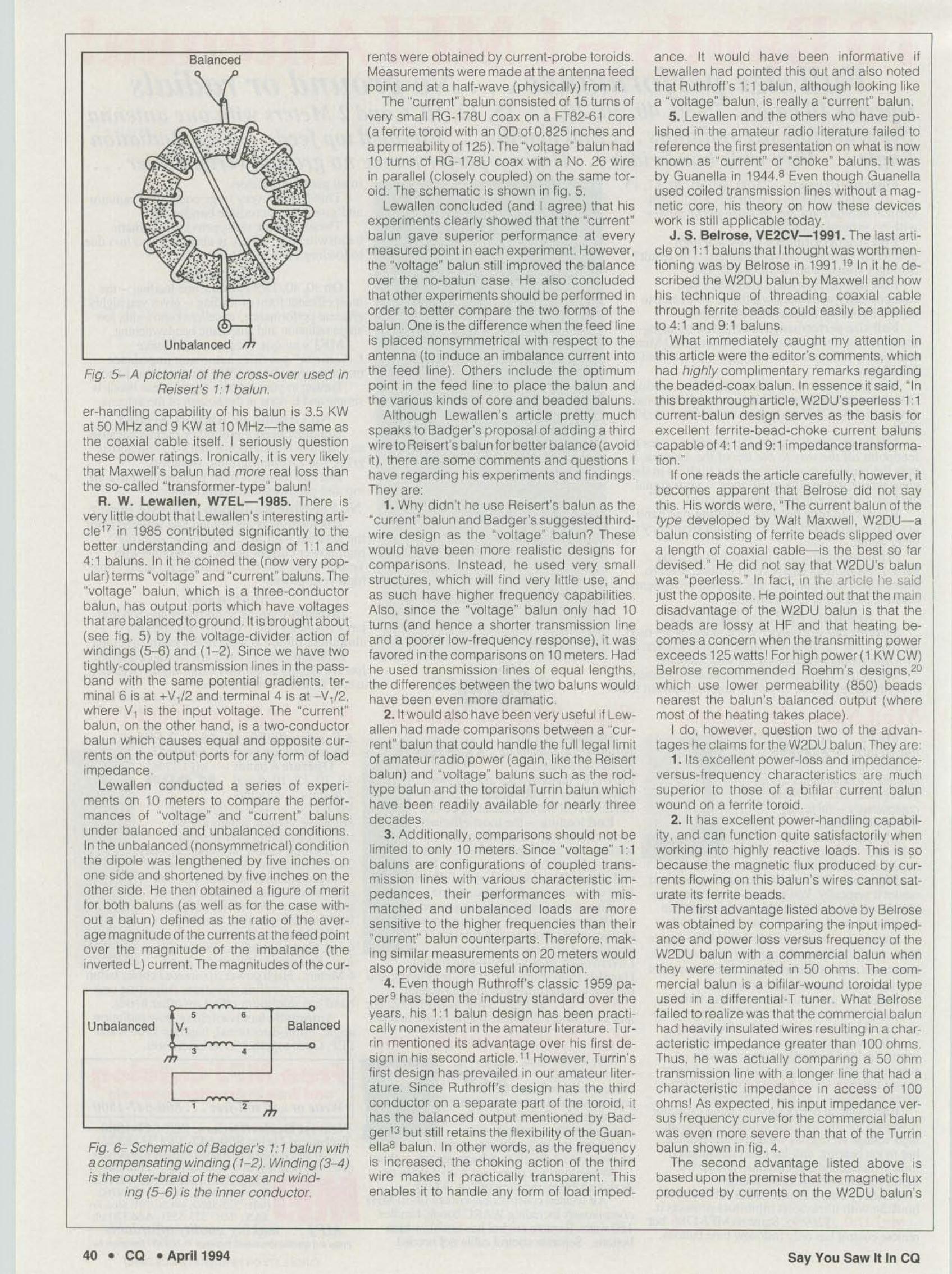
Badger also suggested placing an insulated wire in parallel with the coax winding onReisert's 1:1 balun. He called this a compensating winding . which provided a superior balanced output The schematic is shown in lig6, Later experiments by the author and othershave shown that a well-designed, two-conductor (Guanella) 1:1 balun has a completely satisfactory balanced output for antenna applications. Furthermore, it does not suffer from anunbalanced and/or mismatched load and coresaturation. Incidentally, Badger's schematic offig , 5 now adds up to fourd iflerent versions ofthe 1: 1 balun. They are the two-conductor ver sion of e uaneua's and the three, three-conductor versions of Ruthrofl, runln. and (now)Badge r.
Badger and Orr also mentioned the Collinsbalun in their articles , It is made up of a dummylength of coax which is wound as a continuation of the original coiled coax Wind ing Interestingly, it is connected as a Huthroft 1: 1balun (fig, 2[8]), which also uses a third winding Since there is appreciable coupling between the two coiled windings, the Collinsbalun should also be susceptible to mismatched and/or unbalanced loads. Badgerclaimed il was by far the best 1:1 balun he hadever used. Again, it would have been very informative if he had compared it with the Reisertbalun (without the compensating third wire).
M, W. Maxwell, W2DU-1983. One of themore significant articles on 1:1 barons waspublished by Maxwell in 1983.16Heintroducedwhat hecalled the "choke" balun Itwas formedby placing high-permeability ferrite beads overabout one toot of small (but high-powered)coaxial cables similar to the ones used in theReisert balun. Pnoto E shows the W2DU"cboee" balun removed Irom ItS hOusing,
Maxwell compared his balun With (what hetermed) a "transformer-type" balun by measuring the input impedances versus frequency when the outputs were terminated in 50ohms, Since the "transformer-type" balundidn't yield a true 1: 1 impedance transfer ratio,he claimed it was because of jesses. leakagereactance, and less than octmum coupling.Since he gave no oescrtotco 01 the "trans-
CIRCLE 141 ON READER SERVICE CARO
Say You Saw It In CO Aprill994 • CO • 33

Pin POlll Ie G.lnlNModel (W) [W) [AlldB)ld I 'JI"
NEW!400
WATTSAVG.
(144- '48 M Hzj
50 MHz
r~05036 1-' H)-50 , 15/0.6 LPAosee 1 170 28 15106 Standard0508R , 170 28 + -,.0510G 10 170 25 15/0.6 S""""' -,'0510R 10 17. 25 + Repealer0550' 510 375' 50 15/0.6 HPA
~0550RH 510 375 50 + Repeater HPA0552G 2540 375 ss 15/0.6 HPA0552AH 2540 375 ss + RepealerHPA
144 . Hz1403G 1-' to-SO , 15/0.6 LPAl406G 25 100 12 15/0.6 S""'.1400< 2 150 25 15/0.6 St;nlard •1409R 2 150 24 + Repeater1410G 10 160 25 15/0.6 51""" ~
1410R 10 160 24 + "",...14126 25-4, 160 20 15/0.6 51"""1412R 25-.45 160 19 + _..1450G s 350 56 15/0.6 HPA1450RH s 350 56 + Repeater HPA14526 25 350 50 15/0,6 HPA1452RH 25 350 50 + Repeater HPA Photo F- Two versions of Reisert's 1: 1 balun. The balun on the left uses the cross-over shown1454G 50-100 356 40 15/0.6 HPA in fig, 5. The balun on the rig ht is con tinuously wound Both have the same electrical perfor-1454RH 50-100 356 40 + Repeater HPA mance in the HF band.220 MHz2203G 1-' nl-40 , 14m.? LPA2210G 10 130 20 14/0.7 Staldard2210R 10 130 19 + "",... former-type" balun, I assumed it was the pop- lead or coaxial cable. From Ruthroff's classic2212G 30 130 16 14/{l.7 S""""' utar rod-type ba lun shown in photo C, As you paper.s which extended Guanella's work.e we2212R 30 130 15 + "",... can see in fig 4, this balun has a poor low-I re- became aware 01 the voltage drops along the2250G s 220 40 14/{l.7 HPA2250RH s 256 40 + RepealerHPA quency response. Furthermore, it is really opti- lengths of the transmission lines. And from very?252G 25 220 36 14/{l.7 HPA mized for a load of 47 ohms and not 50 ohms. accurate inse rt ion loss measurernents.a we2252RH 25 256 36 + Repeater HPA But what Maxwell failed to realize was that learned that the losses were mainly in the mag -2254G 75 220 32 14107 HPA his balun wa s a form 01 Guaneua's two-con- netic medium and that they were related to the2254RH 75 256 32 + Repeater HPA440 MHz duetor ba lun, That is, it is both a choke (a voltage levels and the oerrreaonntes. Maxwell4403G 1-' 7-25 4 12/1.1 LPA lumped element) and a transmission line (a didn't take into account these latter find ings,4410G 10 100 19 12/1.1 S...,'" distribu ted element). Additionally, Guanella's He used lossy high-permeabi lity beads (2500)4410R 10 lOG 18 + seoe... theory applies whether the transmission lines and assumed that the main loss was in the44126 20-30 100 19 12/1.1 S,""" are coiled (about a core) or beaded or twin- transmission line, Heclaimed that the CWpow-4412R 20-30 100 18 + "",ater4448G s 100 22 12/1.1 HPA4448R s 100 22 + Repeater HPA4456' 510 175 34 12/1.1 HPA4450RE 510 175 34 + Repeater HPA •4452G 25 175 29 12/1.1 HPA •4452RE 25 175 29 + Repeater HPA4454G 75 175 25 12/1.1 HPA4454RE 75 175 25 + Regeater HPA
RF POWERAMPLIFIERS
•
)ilIIj
Photo G- My high-power design of a bifilar toroidaf (Guanellalcurrent) 1: 1balun mounted in a4 'L x 3'W x 2.2S'H Bud aluminum box,n SflnMS TEL. 13101 471,0591
r.O.lp 25U5 fAI13101.73-4031La _..tin, CA gOOn
TESVSTEMS
50 MHz 05208 ., 25 BNC50 MHz 0520H s 25 N144 MHz 14208 ., 24 ' He144 MHz 1420N .5 24 N220 MHz 22206 .5 22 BNC220 MHz 2220N s 22 N440 MHz 4420 ' s 18 GHC440 MHz 4420N .5 18 N1.2 GHz 1020B .9 14 'He1.2 6Hz 1020N .9 14 N
COnsult rour *-1 'NI. or seoo directly lor furtherI)"odoct information All PnxIlK:ts Made in USA.
11 .1 ~MODEL 14106 MODEL 14508
IU. DAn "P11All af1lililiefs (noo-rpIr) are lnear, es-nooe wKh MyaJtomatic TIR switchng and PTT capability. The re::eiwl)"eafI1lS use GaAs FET dlMces rated ar.s dB NFwKh+ 18(flm 3rd mIer IP, LPA, Standard aoo HPA enos areintBm'ilteotdJIy design stitable lor base and mOOie operalKlnRegeater arTllS are COObfUllS lUy, class C,
Am,lllll., CIIp11bllltlll: HigIt-~, narrow or wideballd;100-200 MHz. 225-400 MHz. 1-2 GHz. Mi~tary (28Vl,Comn'tw'cial, etc. - consul! factay, A CO'f4lIeIe ~ne 01 Rxl)"eafI1lS also available.
RX PreamplifiersNF G.ln
BInd Madel (dB) (dB) Connector
CIRCLE 130 ON READER SERVICE CARD
36 • CO • April 1994 Say You Saw It In CO
Unbalanced
Balanced
Fig, 6- Schematic of Badger's 1: 1 balun witha compensating winding (1-2), Winding (3-4)is the outer-braid of the coax and wind-
ing (5-6) is the inner conductor,
ance. It wou ld have been informative ifLewallen had pointed this out and also notedthat Ruthroff's 1:1 balun, although looking likea "voltage" balun, is really a "current" balun.
5. Lewallen and the others who have published in the amateur radio literature failed torefe rence the first presentation on what is nowknown as "current" or "choke" baluns. It wasby Guanella in 1944.8 Even though Guanellaused co iled transmission lines without a magnetic core, his theory on how these deviceswork is still applicable today.
J . S. Belrose, VE2CV-1991. The last article on 1:1bahms that I thOught was worth mentioning was by Belrose in 1991.19 In it he described the W2DU balun by Maxwell and howhis technique of thread ing coax ial cablethrough ferrite beads could easily be appliedto 4: 1 and 9: 1 batons.
What immediately caught my attention inth is artic le were the editor's comments. whichhad highly complimentary remarks regardingthe beaded-coax balun. In essence it said. "Inthis breakthrough article, W2DU's peerless 1:1cu rrent-balun design serves as the basis forexcellent ferrite -bead-choke current balunscapable of 4' 1 and 9' 1 impedance transformation."
If one reads the article careluity. however, itbecomes apparent that Beirose did not saythis His words were, "The current balun of thetype developed by Walt Maxwel l, W2DU-,balun consist ing of ferrite beads slipped overa length of coaxial cable-is the best so fardevised" He did not say that W2DU's balunwas "peerless' In tact. in the article he saidJust the opposite. He pointed out that the maindisadvantage of the W2DU balun is that thebeads are lossy at HF and that heating becomes a concern when the transmitt ing powerexceeds 125 watts! For high power (1 KW CW)Belrose recorrmendeo Roehm's designs,20which use lower permeability (850) beadsnearest the balun's balanced output (wheremost of the heating takes place),
I do, however, question two of the advantages he claims for the W2DU balun. They are:
1. Its excellent power-loss and impedanceversus-frequency character istics are muchsuperior to those of a bifilar current balunwound on a ferrite toroid
2. It has excellent power-handling ca pability, and can function quite satisfactorily whenworking into highly react ive loads, This is sobecause the magnetic flux prod uced by cu rrents flowi ng on this balun's wires cannot saturate its ferrite beads.
The first advantage listed above by Belrosewas obtained by comparing the input impedance and power loss versus frequency of theW2DU balun with a commercial balun whenthey were terminated in 50 ohms, The commercial balun is a bifilar-wound toroidal typeused in a d iflerential-T tuner. What Belrosefai led to realize was that the commercial balunhad heavily insulated wires resu lting in a characteristic impedance greater than 100 ohmsThus. he was actually comparing a 50 ohmtransmission line with a longer line that had acharacter istic impedance in access of 100ohms! As expected, his input impedance versus frequency cu rve for the commercial balunwas even more severe than that of the Turrinbalun shown in fi9. 4.
The second advantage listed above isbased upon the premise that the magnetic fluxproduced by currents on the W20U balun's
rents were obtained by current-probe toroidsMeasurements we re made at the antenna feedpoint and at a half-wave (physically) from it.
The "current" balun consisted of 15 turns ofve ry sma ll RG-178U coax on a FT82-61 core(a ferrite toroid with an OD of 0,825 inches anda permeability of 125). The "voltage" balun had10 turns of RG-1 78U coax with a No, 26 wirein parallel (closely co upled) on the same toroid , The schematic is shown in fig, 5,
Lewallen concluded (and I agree) that hisexperiments clearly showed that the "current"balun gave superior performance at everymeasured point in each experiment, However ,the "vol tage" balun still improved the balanceover the no-balun ca se He also concludedthat other experi ments should be performed inorder to tetter compare the two forms of thebalun, One is the difference when the feed lineis placed nonsymmetr ical with respect to theantenna (to induce an imbalance current intothe feed line). Others include the optimumpoint in the feed line to place the balun andthe various kinds of core and beaded baluns.
Although Lewallen's artic le pretty muchspeaks to Badger's proposal of adding a thirdwire to Reisert's balun for better balance (avoidit) , there are some comments and questions Ihave regarding his experiments and find ingsThey are:
1. Why didn't he use Reisert's balun as the"current" balun and Badger's suggested thirdwire design as the "vol tage" balun? The sewould have been more realistic designs forcomparisons, Instead, he used ve ry smallstructures. which will find very little use, andas such have higher frequency capabil ities.Also, since the "vol tage" balun only had 10turns (and hence a shorter transmission lineand a poorer low-frequency response), it wasfavored in the comparisons on 10 meters. Hadhe used transmission lines of equal lengths,the differences between the two barons wou ldhave been even more dramatic,
2. lt would also have been very useful if Lewallen had made comparisons between a "current" balun that could handle the full legal limitof amateur radio power (again, like the Reisertbalun) and "voltage" baluns such as the rodtype balun and the toroidal Turrin balun whichhave been read ily available for nea rly threedecades,
3. Additionally, comparisons should not belimited to only 10 meters. Since "voltage" 1 1baluns are config urat ions of coupled transmission lines with va rious character istic impedances, their performances with misma tched and unbalanced load s are moresensitive to the higher frequencies than thei r"current" balun counterparts. The refore , making similar measurements on 20 meters wouldalso provide more useful info rmation.
4. Even though Ruthroff's c lassic 1959 pacere has been the industry standard over theyears, his 1:1 balun design has been practica lly nonexistent in the amateur literat ure. Turnn mentioned its advantage over his first design in his second article.11However, Tumn'sfirst design has prevailed in our amateur literature , Since Ruthroff's design has the thirdco nductor on a separate part of the toroid. ithas the balanced output mentioned by Badger13 but still retains the ftexibilitv of the Guanella8 balun, In other words, as the frequencyis increased, the choking action of the thirdwire makes it practically transparent. Thisenables it to han dle any form of load imped-
Balanced•
t a
, .•Unbalanced VI
Fig 5-- A pictorial of the cross-over used inReisert 's 1'1 balun.
er-handling capability of his balun is 3 5 KWat 50 MHz and 9 KW at 10 MHz-the same asthe coaxial cable itself. I seriously questionthese power rat ings Ironically, it is very likelythat Maxwell's balun had more rea l loss thanthe so-called "transformer-type" balun!
R, W. Lewallen, W7EL-1985. There isvery little doubt that Lewallen 's interesting antcre t? in 1985 contributed signif icantly to thebetter understanding and design of 1: 1 and4: 1 baluns. In it he coined the (now very popular) terms "voltage" and "cu rrent" baluns. The"voltage" balun, which is a three-conductorbalun, has output ports which have voltagesthat are balanced toground .1t is broug ht about(see fig. 5) by the voltage-divider action ofwindings (5-6) and (1-2). Since we have twotightly-coupled transmission lines in the passband with the same potential grad ients, terminal6 is at +V1/2 and term ina l 4 is at - V1f2,where VI is the input voltage. The "current"balun, on the other hand, is a two-conductorbalun which causes equal and opposite currents on the output ports for any form of loadimpedance,
Lewal len conducted a series of experiments on 10 meters to compare the performances of "voltage" and "current" balunsunder balanced and unbalanced conditions.In the unbalanced (nonsymmetncal) conditionthe dipole was lengthened by five inches onone side and shortened by five inches on theother side. He then obtained a figure of meritfor both batons (as well as for the case without a balun) defined as the ratio of the average magnitudeof the currents at the feed pointover the mag nitude of the imbalance (theinverted L) current. The magnitudes of the cur-
40 • CO • April 1994 Say You Saw It In CO

1994CALLBOOKS
THE QSL BOOK!Continuing over a 70 year tradition, webring you two new Callbaoks for 1994 withmore features than ever before.
Photo H- Two "economy"versionsof thehigh-powerbifilartoroidal (Guanella/current) 1.-1 balun.The one on the right uses Reisert's cross-over technique
The 1994 North American Calfbooklists the calls, names, and addresses formore than 500,000 licensed amateurs in allcountries of North America, from Panamathrough Canada, including Greenland,Bermuda, and the Caribbean Islands, plusHawaii and the U.S. possessions. 1,592pages. Item # 087158 (paper) $29.95
The 1994 International CaflbookIists more than 500,000 licensed amateursin countries outside North America, Itscoverage includes South America, Europe,Africa, Asia, and the Pacific area (exclusiveof Hawaii and the U.S. possessions). 1,720pages. Item # 087190 (paper) $29.95
Every active amateur needs the Gal/book!Fully updated and loaded with extra features, the /994 Cal/books will be publishedin December 1993, Order now from yourdealer or send in the coupon below.
Please send me copy(les) ofThe 1994 North American Cal/book(Item # 087158, $29,95) and -c---,-,copy(ies) of The 19941nternalional Cal/book(Item # 087190, $29,95).
I have enclosed my check/money order for$ , (Please add sales tax in CA, DC, IL,MA, NJ, NY, OH, PA, TN, VA & Canada, and$3,00 per book lor postage and handling forU.S. shipments and $7.00 for all shipmentsoutside the U.S.)
Or call and charge on your credit card.MasterCard, VISA and American Express cardsaccepted , Please be sure to include shippinginstructions. Prepayment required and mustbe in U.S, funds.
DRAT 1093
RADIO AMATEURCa libookP.oBox2013 ~,NJ 00701
1-!m-0C6-2961 {Prone} l--OOB--363-{Xll(Fax)
CIRCLE 90 ON READER SERVICE CARD
42 • CO • April 1994
wires cannot saturate the ferrite beads whi lethe wind ings of a bifitar-wound toroidal currentbalun can saturate the core. This is wrongbecause the magnetic flux of a two-conductor type balun such as the beaded-coax orthebifilar-wound toroidal balun is generated bythe imbalance (inverted L) current and henceis much less than the transmission-line currents. Th is is especially true with suffic ientchoking reactances. This impression cou ldvery well come from the perception that thetoroidal-type balun still transmits the energy tothe output circuit by flux linkages.
For high-power beaded-coax barons. Belrose referred to the designs by ncetm.eo whoincreased the power capability of this type ofbalun by using lower permeability beads nearthe ba lanced output. He also increased thelength considerably. For operation from 80meters to 10 meters, he used 28 inches ofbeaded coax, For 160 meters to 10 meters, heused 36 inc hes of beaded coax, WithBelrose's suggestion of connecting beadedcoaxes in pa rallel on the low-impedance sideand in series on the high-impedance side toobtain a broadband 4: 1 transformation ratio, itwould req uire transmission lines with character istic impedances of tooorms .This means,for a high-power 4: 1 balun using beadedtransmission lines, about 56 inches of beaded line would be required for the 80 to 10 meteroperation and 72 inches forthe 160to 10 metercoverage. For a 9:1 balun these lengths wouldeven have to be increased by 50 percent!
The question that remains is what wouldBeirose have said or done if he had comparedthe W20U balun of Maxwell's with the W1JRbalun of Reisert's. He certainly couldn't claimthe advantages listed in his artic le for theW20U ba lun. Would he still have said that thetype of balun developed by Maxwell is the bestso far devised? I doubt it.
J . Sevick, W2FMI-1994. In keeping withthe preceding format, I thought it best to present my latest 1:1 balun designs at this point.
(Ki ts and finished units are available fromAmidon Associates, lnc. , 2216EastG IadwockStreet, Doming uez Hills, CA 90220.) Exceptfor one ba lun that appeared in the June 1993issue of CO, the others are presented here forthe first time. Since I have favored Reisert'sdesign throughout this article, the first baiunsdescribed here are my vers ions of his technique of coiling sma ll (but high power) coaxial cable around a low-permeabilty ferritetoro id. For my wire versions I could have usedall sorts of ad jectives to describe them, suchas GuaneJla, two-conductor, choke, and current. But in the process of writing this section,I thought Belrose's adjectives were the mostdirect. Using his words, I call my wire vers ionsof the 1:1 ba lun simply bifilar toroidal baluns.
Photo F shows two versions of Reisert's balun. The one on the left uses the cross-overshown in fig. 5. Since no difference in pe rformance at HF was noticed without the crossover, a continuous-wound one is also shownon the right. The main advantage in the HFband with the cross-over winding is purelymechanical. Having the input and output connections on opposite sides of the toroid is notonly more convenient. but it also offe rs a muchstronger method of mounting,
For operation from 1.8 MHz to 30 MHz, 10turns of sma ll coax such as RG-303/U. RG142B/U, or RG-400/U are wound on a 2.4 inch00 ferrite toroid with a permeability of 250. Ifthe use is limited from 3.5 MHz to 30 MHz, thena permeability of 125 is recommended, sinceit would yield a slightly higher efficiency at thehigh end, none wants the highest possible efficiency and limits the operation from 14 MHzto 30 MHz, then a permeability of 40 is recommended, With loads g rounded at their centers, these cond itions we re found to g iveample margins (handle a VSRW of 3:1 withoutany appreciable flux) at their low-frequencyends.
For ease of wind ing. I found the TY-RAPCABLE TIES very useful. Two were used at
Say You Saw It In CO

/
Photo 1- Two lOw-power versions of the bltllar toroidal (Guanel/alcurrent) 1." 1 balun capable of handling the output of practically any HF
transceiver The balun on the left has the cross-over
Photo J- Two medium-power versions of the bltllar toroidal(GuanellaJcurrent) 1:1 balun capable 01 handling the full legal limit 01amateur radiO power when the VSWR is less than 2: 1. The balun on
the left has the cross-over.
each end , Also removing the covering on theouter braid help s Since about 24 Inches ofcable is wound on the toroid, starting with atleast 32 inches is recommended Of the threecables noted above, I found RG-303/U cablethe easiest to wind and connect. A lthough itonly has a smqle-Ituckness braid (the othershave double-th ickness braids), its POW8f rating is still the same--9 KW at 10 MHz and 3,5KW al50 MHz
The next high-power desrqn IS srowo Inphoto G mounted in a 4°L x 3'W x 22soH BudCU 234 aluminum box It has 10 bifilar turns 01No, 12 H rreenareze wire on a 2 4 ,nch 00ferrite toroid As with the Reisen versionsbefore, a permeability of 250 is recommended for 1.8 to 30 MHz, 125 for 3,5 to 30 MHz,and 40 for 14t03O MHz, One wire is also covered with two layers of Scotch No , 92 polyimide tape in order to raise the characteristicimpedance to 50 ohms With this added Insulation, the voltage breakdown of this tw in-leadtransmission line compares very favorably withRG-8IU cable (4Q(X) volts), In order to o-eservethe spacing, the wires are also clampedtogether about every '/2 Inch with smos ofScotch No 27 glass tape 3116 inches Wide anda urne over 1 ,nch klng
Two "economy" verso-is or the high-powerblftlar to o oa:balun are shown In c-ote H Theone on the left shows the Windings crowded0f1 one-half 01 the toroid The one on the righthas the same POSItionS of the rnput and outputconnections by uSing the cross-over Theirperformances are identical. Both oaicns have10 bi fila r turns of No, 14 H t bermaieze wire ona 2,4 inch 00 ferrite toroid . The choices of permeability, which trade-oft bandwidth fo r efficiency, are the same as those used in the twoprevious high-power desig ns. As was mentioned at the beg inning , the word "economy"refers to economy In labor.
Ttus balun whICh also handles the fult legalI mit of amateur radio power, has a small tradeoff In high-frequency response Since no extraInsulation IS used, the creracteostc Impedance at two tIQhtly-clamped No 14 H rreenaeze wires IS 45 Ohms With one layer of ScotchNo, 92 tape It Increases to 50 Ohms But lormost of the HF band, the difference m oertor-
44 • CO • April 1994
mance between baluns using transmissionlines of 45 and 50 ohms shou ld be neg ligible.Eve n without the extra Insulation the Voltagebreakdown should compare very favo rablywith the smaller, high-power coaxes used inthe Reisert versions ( 1900 volts).
Photo I shows two low-power versions of ab itilar toroidal balun capable of handling theoutput 01 practically any HF transceiver, Onehas a cross-over winding and the other a continuous winding They both have 10 Milar turnsof No. 16 H r be-re'eze wire on a 125,nchOoternre toroo Wlth a permeability of 250 Sinceeffic iency IS not a major problem In low-poweruse I found no reason to suqqesuheotner twoversions. wtuch use lower oermeaonmes. It isinteresting to note that two tightly clamped No.16 H tfermareze Wires have a charac teristicImpedance close to 50 ohms Therefore, thissmall ba lun (p articularly With its short leads)has a very good high-frequency response,
Photo J shows two medium-power versionsof a b ifl lar toroidal balun capab le of handlingthe full legal limit 01 amateur radio power undercontrolled corouoos-wneo the VSWR is lessthan 21. Being smaller than its larger (2,4 inch00) counterpart. ItS heat-Sinking capability,and hence power rating, IS less As before. onebalun uses a cross-over wtlile the other doesnot. Each has 8 Milar turns 01No 14 H Thermaiezeweecoa t.smcnooremtetoeoo Theferrite penreatxunee and expected bandwidths are the same as With the other highpower bakms Since the average magneticpath length In the core is about two-thirds tha tof the 2 4 Inch core, only 8 b ifi lar turns arerequired in order to produce a similar low-frequency capability. Even though the charac teristic impedances of their bifirar Wind ings are45 ohms, their responses on 10 meters shouldbe somewhat better than the "economy" models, since the lengths cttheir iranemssron hnesare shorter (18 compared to 24 Inches).
And now a lew words on what sort of effi ciency one can expect In tradlng-off tow-frequency response by usmq ower permeabilityterreeco-es From earlier srucesut was loundthat the etlICI80CY (With suthcent choking soonly neremeeoo line currents flOw) is relatedto the permeabIlity, the voltage drop along the
length of the transmission line. and the frequency , The higher the permeability and/orvoltage. the greater the loss Additionally, thehigher the permeabi lity. the grealer is the losswith frequency. It was also found that a permeability 01 less than 300 was necessary inorder to obtain the very high etuciencies ofwhICh these devices are capable.
From the results 01 the sno.es. here aresome emceoces that mighl be expected fromterues under matched ccoouoos.
1. With 250 material, an elf,c,ency near 99percent at 1 8 MHz and 97 percent at 30 MHz.
2. With 125 material, an et nceocv near 99percent at35 MHz and 98 percent at 30 MHz.
3. With 40 material, an erncercvof 99 percent at 14 MHz and at 30 MHz ,
When a balun is exposed to a high impedance resulting in a VSWR 01 2:1, the voltage,and hence loss, increases by about 40 percent With a VSWRof4, 1the loss doubles ,Witha VSWR 01 10:1 the loss is more than threefo ld , Since limited data was obtained in thisstcov.emese Increases in losses With increases In VSWR could very well be greater
Summary
In prepannq this arucie I was QUite surprisedto stili see the temte- and powdered-iron-core1 1 balun cesons that have been available inthe literature and elsewhere smce 1964 Theyno! only had poor low- and high-frequencyresponses, but they were also susceptib le toflux In the cores at the ir low-frequency endsFurther more, since they onl y used single-coated Wires, they were also prone to vo ltagebreakdown No doubt. these designs were responsible for the poor reputation that the balunhas had for many years
II wasn't until 1978, when Reisert publishedhis article. that a balun became available Withan 01 the attributes of a good oesqn. namely'
a) Is euceor because It uses a cw-oenreaMity core.
b) Has sutncent choking reactance to meetItS low-frequency requirement
c) Is not prone to flux in the core (and hence,saturation) smce it has no third winding.
Say You Saw It In CO

References
t=~t-;B:a l,ancec~~=:'~~_:Ioad
Correction To February ArticleIn the February issue of CQ on page 28,
"A Subsequent Look At4:1 Baluns." also byW2FMI, fig , 2 was incorrect ,The pictorial rep resentaton of the 4:1 Authroff (voltage) balunis as shown here.
Matching Transformer," Co. August 1992,pages 13-18 ,
5 Jerry Sevick, W2FMI. "A Balun Essay,"Co. June 1993, pages 50-59.
6. Richard A Genaiue . W4UW. "How toBuild a Multi-Tap Unun," CO. May 1992, pages28- 32.
7. Bruce Eggers, WA9NEW, "An Analysis ofthe Balun," OS T, Ap ril 19S0, pages 19-21,
8. G, Guanelra. "Novel Matching Systemslor High Frequenc ies," Brown-Boven Review.Volume 31 , September 1944, pages 327-329
9. C. L Ruthroff, "Some Broad-Band Transformers," Proceedings of/he IRE, Volume 47,August 1959. pages 1337-1342.
10. Richard H. Turrin, W2IMU, "Broad-BandBalun Transformers," QST. August 1964,pages 33-35.
11. Richard H Turrin, W21MU, "Applicationof Broad-Band Balun Transtorrners." OST,April 1969, pages 42 , 43
12,Joe Reisert, W1JR, "Simple and EfficientBroad band Balun: Ham Radio, September1978, pages 12- 15,
13 George Badger. W6lC, "A New Classof Coaxial-Li ne Transformers. Part 1," HamRadio, February 1980, pages 12- 18
14. George Badger. W6lC, "A New Cla ssof Coaxial-line Transformers, Pan 2," HamRadio. March 1980, pages 18-29, 70.
15. Bill Orr , W6SAI. "Radio Fundamentals:The Coax Balun." CO,November 1993. pages60-£5.
16 , Walt Maxwell, W2DU , "Some Aspects ofthe Balun Problem," QST, March 1983, pages38---40.
17. Roy Lewallen, W7EL, "Bahms: WhatThey Do and How They Do It," The ARRL Antenna Compendium.Volume 1,Amateur RadioRelay League, Newington, Connecticut, 1985,pages 12- 15
18 Jerry Sevick. W2FMI. "Baiuns for Antenna Tuners," CQ. November 1993, pages50-59.
19. John Belrose . VE2CU, "Transformingthe Balun," QST, June 1991 , pages 30-33.
20. Albert Roehm, W20BJ , "Some Additional Aspects of the Balun Problem," The ARRLAntenna Compendium, Volume 2, AmateurRadioRelay League , Newington,Connecticut.pages 172-174, •
Amilablefrom yo"r
wier...
Add $4.00 ShiWing & Handling lor first battery.n.mlor each add1 battery' US. on~'
ConnEcticut Il"Sidl'nlS .1lkI6% tax.
1, Jerry Sevick, W2FM I, "More on the 4: 1 Balun," Co. February 1994, pages 28-36
2. Jerry Sevick, W2FMI, "Baluns Revisited ."commomceuore Quarterly. Summer 1992.pages 13-18
3. Jerry Sevick , W2FMI, Transmission LineTransformers,2nd ed ition, Amateur Rad io Relay league, Newington, Connecticut, 1990.
4. Jerry Sevick, W2FM I, "The 2:1 Unun
Now Only '40 Ea:h• One Year Warranty• Matched cell ronstruction• Case rebuild selVice• Long life, extended operating lime• Madefor HAMS, by HAMS
urate, while the bifilar (current) toroidal balunca n, This is entire ly wrong, since they are basica lly the same kind of structure-neither hasa th ird conductor which could allow a fluxcausing current at the very low-frequency endBut of all of the attributes fisted above for theReisert balun, the first one has the "choke"balun at ad isadvantage in the HF band, Sinceits traosrrusson line is not coifed about a toro id,it does not have the mu ltipfication teeter of N2(due to mutual coupling). where N is the number of turns , wh ile the to roidal balun doesTherefore, higher-permeability beads are required in order to obtain suff icient chokingreactance. This results in lower effic iency
And finally, I am quite sure that some readers of this article wi ll d isagree with my viewsand/or think they have better designs thanthose of the Reisert barons and the ones ' presented here, If so, I encourage them to respond In print. In this way we will all benefitfrom the new information
EBp·24S AilliCO l500ma S62.00
"ii!!iiiiiP. RlPt lG'X iJ,~.the only thing low about our charge is the cost.. .
1-800-634-8132
d) Has a 50 ohm characteristic Impedanceand thus maintains a 1:1 transformation rat iowith a 50 ohm load ,
e) Has a good voltage breakdown capability (1900 volts).
f) Can handle a mismatched and/or unbalanced load ,
Succeed ing Investigators, however. failedto see the advantages of his design and proposed their own. Surprisingly, they belongedto two distinct groups One favored "air-core"baluns and the other "choke" (beaded-coax)baluns
The main argument given by the "air-core"fo llowers was that their balun would neverexperience the problems with saturat ion wh ilethe "ferr ite-core" balun wou ld. The Reisert balun, however, is a current/choke type balunwhich could on ly have flux in the core by theimbalance (inverted L) current, which is muchsmaller than the transmiss ion-l ine currents. Infact, with any degree 01 ch oking reactance bythe coiled transm iss ion line, the imbalanc ecurrent is essentia lly neglig ib le , The refore,saturation is not a concern with a balun suchas Reisert's. But in all fa irness, It shou ld bepointed out that with the 4: 1current/choke andvoltage bafuns it is a different story. All threeor these types 01 baluns have a "magnetizinginductance" in their low -frequency modelsand hence a possib ility of saturation with apoor design.
The advocates of the "choke" 1:1 balunc laim that the ir beaded- coax balun can't sat-
115·18 Hurley Road' Oxford, cr 06478' (2Q3) 264-3985 • FAX (203) 262-6943CIRCLE B4 ON REAOER SERV ICE CARD
46 • co • April 1994 Say You Saw It In CO