Embed Size (px)
Citation preview
Parallel Computing 18 (1992) 355-358 355 North-Holland
Short communication
More on systolic line drawing
G.M. Megson a and D.J. Evans b
a Computing Laboratory, The University, Claremont Tower, Claremont Rd, Newcastle-Upon-Tvne, NEI 7RU, UK b Parallel Algorithms Research Centre, University of Technology, Loughborough, Leicestershire, LEII 3TU, UK
Received 15 April 1991
Keywords. Assignment problem iteration (API); systolic array; systolic control ring instruction processor (SCRIP); Hungarian method.
1. Introduction
In [!] the authors proposed a systolic algorithm for computing the solution to the assignment problem using the so-called Hungarian algorithm .'~e algorithm was mapped onto the systolic control ring instruction processor (see [2] for description and examples) a variation of the wavefront processor array [4], and the instruction systolic array [5].
An important part of the Hungarian method is the selection of a minimal set of lines to cover the zeroes in the current reduced cost matrix. When the number of lines is equal to the order of the cost matrix the algorithm terminates with an optimal solution. The unpredictabil- ity of the line positions implies irregular data flow and so to produce a simple wavefront data flow [1] suggested a line drawing heuristic.
In this short note we re-examine the line drawing problem ~nd suggest an efficient mechanism for implementing the line drawing mechanism discussed in [3]. We show that a single SCRIP cycle is equivalent to two updates using the row and column marking algorithm. The new line drawing procedure is more powerful than the previous heuristic and guarantees the minimal set of lines at each stage.
2. Line drawing
Given an n × n matrix representing a reduced cost matrix (i.e. position i, j is representa- tive of the cost of assigning job i to person j for example). Initially zeroes are introduced into the cost matrix by subtracting the minimum element in each c~lumn from the other elements in the same column, then repeating the process for the rows. An optimal assignment is determined by attempting to draw lines through the available zeroes. At each stage we must use the minimum number of lines. If at any stage n lines are required the solution is optimal and the algorithm terminates. If less than n lines are necessary the cost matrix is updated by locating the minimum among the uncovered elements and subtracting or adding the value to matrix elements depending upon whether they are twice covered (two lines through them) or uncovered (no lines through them). The process of line drawing is then repeated.
0167-8191/92/$05.00 © 1992 - Elsevier Science Publishers B.V. All rights reserved
356 G.M. Megson, D.I. Evans
The minimal set of lines can be drawn as follows: Step I (circling zeroes). Find the row with the fewest zeroes and circle one zero. Next
strike out all zeroes in the same row and column. Repeat the process for all the rows. Step 2 (Marking rows and columns). (a) Mark every row that contains no circled zero. (b)
Mark every column with at least one zero struck out in a marked row. (c) Mark every row that has a circled zero in a marked column. (d) Repeat (b) and (c) until no new marks are made.
Step 3 (Draw lines). Lines can be drawn through unmarked rows and marked columns. If n lines have been drawn the optimal solution has been found.
Below we show how this procedure is mapped onto the SCRIP architecture.
3. SCRIP algorithm
The implementation of Steps 1-3 above are best illustrated by recourse to a suitable example. We also assume that the reader is familiar with the operation of the SCRIP [2] and the algorithm in [1]. The cost matrix is pre-loaded into the SCRIP mesh.
Suppose we have the following 5 x 5 example
0 1 0 2 3 4 0 5 6 0 7 8 9 0 10 0 0 11 12 13
14 15 16 0 17 It is simple to show that only four lines are required to cover the zeroes so that the solution is not optimal. To determine which lines to draw we proceed as follows:
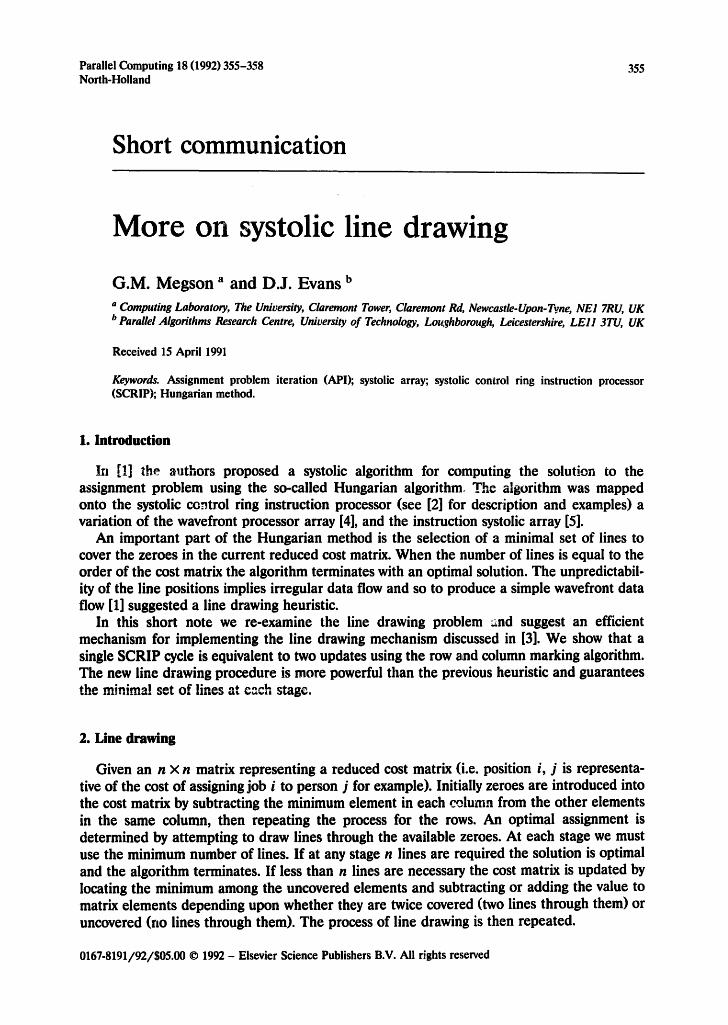
(i) Count the number of zeroes in each row and sort rows so that the minimum row zero count lies adjacent to c 3. Sorting is achieved by a wavefront from c 2 to c 3 which propagates an accumulating zero count from left to right storing the final values in the last column of cells. The counts are sorted and exchange signals propag:~ted back across the mesh to re-align the swapped rows. By a similar process we can sort columns (although this is not necessary).
c i c 2 c I c 2
0 1 0 2 3 2 0 1 2 0 :3 2
4 0 $ 6 0 2 4 0 6 5 0 2
7 8 9 0 10 1 ~ 0 0 12 11 13 2
0 0 11 12 13 2 7 8 0 9 10 1
14 15 16 0 17 1 14 15 0 16 17 l
c 4 2 2 1 2 1 c 3 c 4 2 2 2 1 1 c 3
(ii) Locate circled zeroes using n-wavefronts from c 3 to c n. The natural wavefront progression allows the striking out of the remaining row and column zeroes.
N. c I ,c" 2 c I c2
0 1 2 0 ,3" 0 K i 2 [ ] 3 0 . f ~.J "
4 0 6 s - 0 4 6 5 0
o o n," , ~ ~" - . . o ~ ~ 12 nl 13 o
1 ,, I . l 7 8 )~ 9 10 0 . s / f . • / ~ / / .
I ~ ~ " 01~" 16" ~Y 0 0 14 15 [-6] 16 17 0
~t~41..,/ , , / ' t / " / / " c 3 c 4 c3 j .
More on systolic line drawing 357
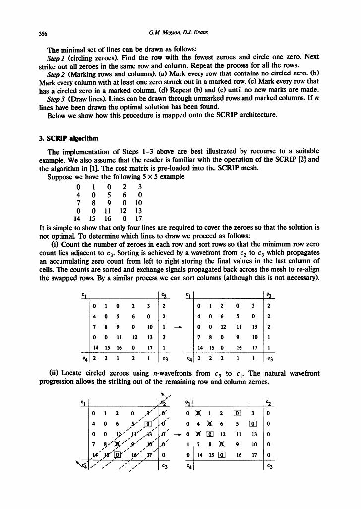
(iii) Mark the co lumns using a wavefront from c 4 to c 2. A set of markers held in the last row of the array is propagated with the wavefront and gets loaded into the first row of the array.
% / ~2 ~, 0 0 , 0 0 °2
0 ~1~. l 2 ~0] 3 0 0 ~8~ l 2 [-6-] 3 0
0 4 ~ l !~ .6 5 [ - 0 - 7 0 0 4 ~ 8 ( 6 5 VO-] 0
0 ~( ~ h . 11 13 0 - ~ 0 ~ 70-1 12 11 13 0
1 ? 8 ~ 9 " . 10 0 1 7 S ~ 9 10 0
o ~4 isl--6l 16 "l~,.j o 14 15 N ~6 17 o
c 4 0 0 0 0 0 "'r~. c 4 0 0 0 0 0 c 3
(iv) Mark the rows using a wavefront from c ! to %. Both the row and co lumn markers can be propagated across and down the mesh and compared with previous values. As signals indicating any changes to markers can be shifted towards c 3 along the last row and co lumn to determine if more marking iterations are required. At the time lines can be drawn through the internal mesh cells.
/ c I 0 0 1 0 0 ,e~"~ c I 0 0 1 0 0 c 2
/
O ) ~ ' I UL"~"J "" O / / O " u ~ " I ~ v ~ 3 O
/ / 0 11 13 0 ~ 0 ~ , I A-I ' " "" 0
/
1 7 ,,'8"" ~ 9 10 0 1 7, 8 9 10 1 A-v -*~ ! ~ . l . . I 0 ..J~" 15 [ ~ 16 17 0 0 • ,c ~ . . . . 1
/¢4 ¢'~0 0 0 0 0 c 3 c 4 0 0 1 0 0 c 3
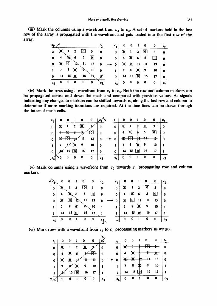
(v) Mark co lumns using a wavefront from c 2 towards c 4 propagating row and co lumn markers
~e l , L 0 o I o o c 2 c! o o l o o c 2
o "~, ~ 2 [ ] 3 o o ~ I 2 [ ~ 3 o
0 4 '~.6 5 VO-] 0 0 4 )[~ 6 5 F-o[ 0
0 ~8~ [ -~ "I~-,, II 13 0 ~ 0 ~ O~ 12 !! 13 0
7 8 ~ .0'- !o I t 7 8 ~ 9 10 1 • %
1 14 15[-67 16 17 . 1 1 14 15 N 16 17 1 '-.%
c 4 0 0 ! 0 0 c,~. c 4 0 0 ! 0 0 c 3
(vi) Mark rows with a wavefront from c 3 to c~ propagating markers as we go.
c I 0 0 1 0 0 [ e~ Cl 0 0 1 0 0 c 2 /
o ~ ~ 2 !-61 ~-" o o - ~ s ~ ~ , ~ - ~ - - - ~ - o
0 4 ~8~ 6 , ~ e _ ~ 0 0 - - 4 - - - - ~ ~ 0
o ~ I-6-1 ja'" ': :~ o - - * o ~ t - - - - P , - - ~ o
1 7 .8"""~8~ 9 10 1 1 7 8 )1~ 9 10 1 /
1 J ~ 15 ~ 16 17 1 1 14 15 []~ 16 17 1 /
~>¢~ 0 0 l 0 0 c 3 c 4 0 0 l 0 0 c 3
358 G.M. Megson, D.J. Evans
Observe that (iii)-(vi) constitute only a single cycle around the SCRIP control ring - this is because wavefronts can be overlapped and pipelined behind one another. For an n x n matrix we require an (n + 1) x (n + 1) SCRIP so that cycle costs 4(n + 1) steps in total. Each cycle performs two row and column marking steps. (ii) Requires n wavefronts which can be pipelined behind one another. As a single wave requires 2n steps to propagate across the mesh we require 2n + n --- 3n steps altogether. It follows that if 8 is the number of iterations in step (ii) of the algorithm to determine row and column markers we require
4(n + 1)~/2 + 3n -- 2( n + 1)/~ + 3n
steps to draw a minimal set of lines. Thus for S iterations of the Hungarian method on the SCRIP architecture we require
S T-~ 2nS + 2(n + 1) ~ ~i
i=1
steps where 8 i is the r~mber of row and column marking steps at iteration i.
Summary
A more complete description of a systolic line-drawing algorithm for implementing the Hungarian algorithm on a SCRIP architecture has been proposed. The method replaces the former heuristic used in [1] and guarantees that the minimal number of lines will always be drawn at each stage.
Acknowledgement
The authors would like to thank O. de Lame, for his constructive comments on the line drawing heuristic which have led to this revised form of the method.
References
[1] G.M. Megson and D.J. Evans, An orthogonal systolic design for the assignment problem, Parallel Comout. 16 (1990) 263-267.
[2] G.M. Megson and D.J. Evans, The systolic control ring instruction processor (SCRIP), Integration 9 (1990) 287-302.
[3] A. Kaufmann, Methods and Models of Operations Research (Prentice-Hall International Series in Management, Prentice-Hall, Englewood Cliffs, NJ, 1963) 68-71.
[4] S.Y. Kung, On supercomputing with systolic/wavefront array processors, Proc. IEEE, 72 (7) (1984) 4-22. [5] H.W. Lang, The instruction systolic array, a parallel architecture for VLSI, Integration, 4 (1986) 65-74.