Embed Size (px)
Citation preview

More is Less, Less is More:Molecular-Scale Photonic NoC Power Topologies
Jun PangDepartment of Computer Science
Duke [email protected]
Chris DwyerDepartment of Electrical and
Computer EngineeringDuke University
Alvin R. LebeckDepartment of Computer Science
Duke [email protected]
AbstractMolecular-scale Network-on-Chip (mNoC) crossbars usequantum dot LEDs as an on-chip light source, and chro-mophores to provide optical signal filtering for receivers.An mNoC reduces power consumption or enables scaling tolarger crossbars for a reduced energy budget compared tocurrent nanophotonic NoC crossbars. Since communicationlatency is reduced by using a high-radix crossbar, minimiz-ing power consumption becomes a primary design target.Conventional Single Writer Multiple Reader (SWMR) pho-tonic crossbar designs broadcast all packets, and incur thecommensurate required power, even if only two nodes arecommunicating.
This paper introduces power topologies, enabled byunique capabilities of mNoC technology, to reduce over-all interconnect power consumption. A power topology cor-responds to the logical connectivity provided by a givenpower mode. Broadcast is one power mode and it consumesthe maximum power. Additional power modes consume lesspower but allow a source to communicate with only a stat-ically defined, potentially non-contiguous, subset of nodes.Overall interconnect power is reduced if the more frequentlycommunicating nodes use modes that consume less power,while less frequently communicating nodes use modes thatconsume more power. We also investigate thread mappingtechniques to fully exploit power topologies. We explore var-ious mNoC power topologies with one, two and four powermodes for a radix-256 SWMR mNoC crossbar. Our resultsshow that the combination of power topologies and intelli-gent thread mapping can reduce total mNoC power by up
Permission to make digital or hard copies of all or part of this work for personal orclassroom use is granted without fee provided that copies are not made or distributedfor profit or commercial advantage and that copies bear this notice and the full citationon the first page. Copyrights for components of this work owned by others than ACMmust be honored. Abstracting with credit is permitted. To copy otherwise, or republish,to post on servers or to redistribute to lists, requires prior specific permission and/or afee. Request permissions from [email protected] ’15, March 14–18, 2015, Istanbul, Turkey.Copyright c© 2015 ACM 978-1-4503-2835-7/15/03. . . $15.00.http://dx.doi.org/10.1145/2694344.2694377
to 51% on average for a set of 12 SPLASH benchmarks.Furthermore performance is 10% better than conventionalresonator-based photonic NoCs and energy is reduced by72%.
Categories and Subject Descriptors C.1.2 [Multiple DataStream Architectures (Multiprocessors)]: Interconnection ar-chitectures
Keywords Nanophotonics; Interconnection Network; En-ergy Efficiency
1. IntroductionNanophotonic Network-on-Chips (NoC) exhibit superiorpower delay product and bandwidth compared to electricalNoCs [19, 27, 28, 36] and are likely to play an important rolein next generation NoCs. The ideal NoC is one large cross-bar that enables communication between all pairs of nodesin the absence of output conflicts. Unfortunately, currentring resonator based crossbars are difficult to scale largerthan 64×64 due to ring thermal tuning, ring nonlinearity,and external light source inefficiency.
Recently proposed Molecular-scale Network-on-Chip(mNoC) designs use emerging molecular-scale devices toconstruct nanophotonic networks [29, 30]. Quantum dotLEDs (QD LED) provide on-chip electrical to optical sig-nal generation/modulation and chromophores provide op-tical signal filtering for receivers. These molecular devicesreplace the ring resonators and external laser source usedin current nanophotonic NoCs. For a simple Single WriterMultiple Reader (SWMR) crossbar, mNoC reduces energyconsumption or enables scaling to larger crossbars (morethan radix-256) for a smaller energy budget and with betterperformance compared to ring resonator NoCs.
Communication latency and power consumption are twoimportant factors in NoC design. Communication latency isreduced in high radix (e.g., 256×256) SWMR mNoC cross-bars since there are no intermediate routers and optical sig-nals transmit at the speed of light. Therefore, power con-sumption becomes a top concern in mNoC design. In con-
283
ventional SWMR crossbars, a source node broadcasts ev-ery packet and consumes power necessary to reach everydestination even with only one or a few destination nodes.Furthermore, broadcast ignores frequency of communica-tion between a source and specific destination nodes. Thechallenge is to design a single physical interconnect that pro-vides the latency benefits of high-radix crossbars, but with-out the worst case broadcast power consumption for frequentcommunication to subsets of destinations.
To meet the above challenge, this paper introduces mNoCpower topologies, a unique capability where connectivity isdynamically controlled as a function of source power (Con-tribution 1). For a given source on a single waveguide,broadcast requires the highest power since it reaches all des-tinations, whereas lower power modes provide connectivityto progressively smaller subsets of destination nodes. Theability to control the on-chip QD LED light source powerand the appropriate design of optical waveguides enablesdifferent power modes. In particular, we use asymmetricwaveguide splitters to allow potentially non-contiguous des-tinations in each power mode.
This paper explores static power topologies with a fixedset of source power modes. The specific power mode is se-lected dynamically based on destination. Our designs areguided by examining program communication patterns. Thegeneral design problem is NP-hard, therefore we use heuris-tic methods to design several power topologies with one,two, and four power modes (Contribution 2). We also ex-plore the impact of thread mapping, since overall power isreduced if frequently communicating nodes use the lowestpower modes, while less frequently communicating nodesuse higher power modes (Contribution 3).
We use Graphite [25] to evaluate performance and togather execution traces of several SPLASH-2 benchmarks [37]executing on a 256 core system. The traces are used to ex-amine communication patterns and to compute NoC powerconsumption. Our results show that total mNoC power con-sumption is reduced by around 13% for naive power topolo-gies, whereas a communication-aware power topology thatutilizes intelligent thread mapping reduces power by 51%.The best overall design achieves performance 10% betterthan conventional resonator-based photonic NoCs while re-ducing energy by 72% (Contribution 4).
The remainder of this paper is organized as follows. Sec-tion 2 introduces background information for mNoC and themotivation of our work. We present power topologies andtheir implementation in Section 3 and Section 4 discusses ar-chitecting power topologies. In Section 5 we evaluate severalpower topologies and the impact of thread mapping. Relatedwork is discussed in Section 6 and we conclude in Section 7.
2. Background and MotivationNanophotonic NoCs are promising since they provide highbandwidth and lower power than conventional electrical
(a)
(b)
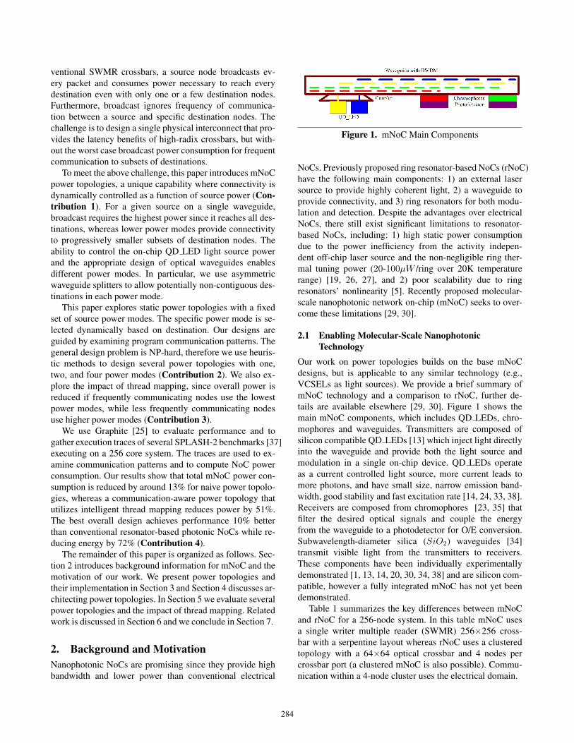
Figure 1. mNoC Main Components
NoCs. Previously proposed ring resonator-based NoCs (rNoC)have the following main components: 1) an external lasersource to provide highly coherent light, 2) a waveguide toprovide connectivity, and 3) ring resonators for both modu-lation and detection. Despite the advantages over electricalNoCs, there still exist significant limitations to resonator-based NoCs, including: 1) high static power consumptiondue to the power inefficiency from the activity indepen-dent off-chip laser source and the non-negligible ring ther-mal tuning power (20-100µW /ring over 20K temperaturerange) [19, 26, 27], and 2) poor scalability due to ringresonators’ nonlinearity [5]. Recently proposed molecular-scale nanophotonic network on-chip (mNoC) seeks to over-come these limitations [29, 30].
2.1 Enabling Molecular-Scale NanophotonicTechnology
Our work on power topologies builds on the base mNoCdesigns, but is applicable to any similar technology (e.g.,VCSELs as light sources). We provide a brief summary ofmNoC technology and a comparison to rNoC, further de-tails are available elsewhere [29, 30]. Figure 1 shows themain mNoC components, which includes QD LEDs, chro-mophores and waveguides. Transmitters are composed ofsilicon compatible QD LEDs [13] which inject light directlyinto the waveguide and provide both the light source andmodulation in a single on-chip device. QD LEDs operateas a current controlled light source, more current leads tomore photons, and have small size, narrow emission band-width, good stability and fast excitation rate [14, 24, 33, 38].Receivers are composed from chromophores [23, 35] thatfilter the desired optical signals and couple the energyfrom the waveguide to a photodetector for O/E conversion.Subwavelength-diameter silica (SiO2) waveguides [34]transmit visible light from the transmitters to receivers.These components have been individually experimentallydemonstrated [1, 13, 14, 20, 30, 34, 38] and are silicon com-patible, however a fully integrated mNoC has not yet beendemonstrated.
Table 1 summarizes the key differences between mNoCand rNoC for a 256-node system. In this table mNoC usesa single writer multiple reader (SWMR) 256×256 cross-bar with a serpentine layout whereas rNoC uses a clusteredtopology with a 64×64 optical crossbar and 4 nodes percrossbar port (a clustered mNoC is also possible). Commu-nication within a 4-node cluster uses the electrical domain.
284
Metric of Interest rNoC mNoCTechnology Characteristics
Wavelength (nm) 1550 390-750Requires Thermal Tuning Yes No
Activity/traffic independent light source Yes NoNonlinearity (transmitters & receivers) Yes No
System Evaluation MetricsScalability (Max crossbar size) 64×64 > 256×256Normalized energy (256-node) 1 < 0.51
Normalized performance (256-node) 1 1.1
Table 1. Comparison between rNoC and mNoC
• Scalability: rNoC scalability is limited by either nonlin-ear device behavior or ring thermal tuning power. SincemNoCs do not utilize rings and neither QD LEDs [31]or chromophores exhibit nonlinear behavior, waveguidenonlinearity is the primary limitation to mNoC scalabil-ity. An mNoC crossbar can easily scale to more thanradix-256 even with a 2dB/cm loss waveguide. Withmultilayer silicon integration [5] even higher scalabilitymay be achievable.
• Energy and Performance: Overall energy consump-tion is reduced because mNoC eliminates the large ringthermal tuning power. Moreover, the off-chip activity-independent laser source is replaced with on-chip QD LEDs,where the waveguide link utilization and per packet 1-to-0 ratio play an important role in further reducing energyconsumption. Previous work [29, 30] shows that for a256-node clustered design with a radix-64 optical cross-bar, the clustered mNoC (c mNoC) reduces energy by77% for the same performance compared to rNoC. Whenscaled to a single 256×256 crossbar (not possible forrNoC), mNoC achieves a 49% energy reduction witha 10% increase in performance vs. the clustered rNoCtopology.
2.2 MotivationThe above results demonstrate the potential benefit of mNoCtechnology over rNoC technology by providing more scala-bility (and thus performance) with lower energy consump-tion. We also observe that, for a 256-node system, c mNoCachieves the largest energy reduction while the full 256×256mNoC crossbar achieves the highest performance. Althoughit is possible to construct multiple networks to provide ei-ther low power or high performance when needed (e.g., cat-nap [11]), ideally we want a single physical network thatprovides the performance of the high radix crossbar (mNoC)with the energy savings of the lower-radix clustered topology(c mNoC).
Our work toward achieving this goal is motivated bythree primary observations: 1) source power consumptiondominates overall mNoC power consumption, 2) waveguide
0
10
20
30
40
50
60
70
80
90
0 2 4 6 8 10
Po
we
r C
on
sum
pti
on
in
mN
oC
(%
)
Minimum Input Optical Power (mIOP, unit: uW)
O/E
QD_LED
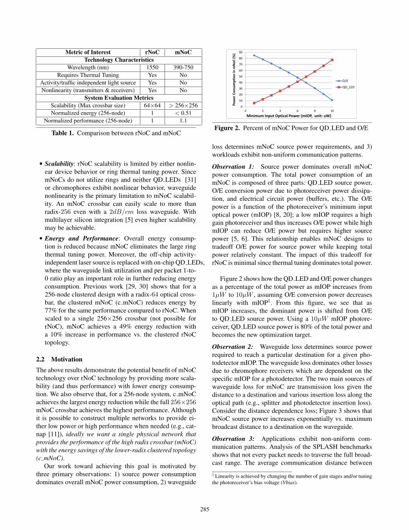
Figure 2. Percent of mNoC Power for QD LED and O/E
loss determines mNoC source power requirements, and 3)workloads exhibit non-uniform communication patterns.
Observation 1: Source power dominates overall mNoCpower consumption. The total power consumption of anmNoC is composed of three parts: QD LED source power,O/E conversion power due to photoreceiver power dissipa-tion, and electrical circuit power (buffers, etc.). The O/Epower is a function of the photoreceiver’s minimum inputoptical power (mIOP) [8, 20]; a low mIOP requires a highgain photoreceiver and thus increases O/E power while highmIOP can reduce O/E power but requires higher sourcepower [5, 6]. This relationship enables mNoC designs totradeoff O/E power for source power while keeping totalpower relatively constant. The impact of this tradeoff forrNoC is minimal since thermal tuning dominates total power.
Figure 2 shows how the QD LED and O/E power changesas a percentage of the total power as mIOP increases from1µW to 10µW , assuming O/E conversion power decreaseslinearly with mIOP1. From this figure, we see that asmIOP increases, the dominant power is shifted from O/Eto QD LED source power. Using a 10µW mIOP photore-ceiver, QD LED source power is 80% of the total power andbecomes the new optimization target.
Observation 2: Waveguide loss determines source powerrequired to reach a particular destination for a given pho-todetector mIOP. The waveguide loss dominates other lossesdue to chromophore receivers which are dependent on thespecific mIOP for a photodetector. The two main sources ofwaveguide loss for mNoC are transmission loss given thedistance to a destination and various insertion loss along theoptical path (e.g., splitter and photodetector insertion loss).Consider the distance dependence loss; Figure 3 shows thatmNoC source power increases exponentially vs. maximumbroadcast distance to a destination on the waveguide.
Observation 3: Applications exhibit non-uniform com-munication patterns. Analysis of the SPLASH benchmarksshows that not every packet needs to traverse the full broad-cast range. The average communication distance between
1 Linearity is achieved by changing the number of gain stages and/or tuningthe photoreceiver’s bias voltage (Vbias).
285

0
0.1
0.2
0.3
0.4
0.5
0.6
0.7
0.8
0.9
1
2 4 8 16 32 64 128 256
Maximum broadcast distance(nodes)
So
urc
e p
ow
er
con
sum
pti
on
rela
tiv
e t
o 2
56
-no
de
bro
ad
cast
Figure 3. Source Power Consumption vs. Broadcast Dis-tance
threads, based on thread ID numbered from 0 to 255, is 102across 12 SPLASH benchmarks. Therefore, broadcasting toall the nodes is not always power efficient and it should beused only when needed. Furthermore, the amount of com-munication between nodes is not evenly distributed, somenodes communicate more frequently than others, similar ob-servations for both SPLASH and Parsec are presented byBarrow-Williams, et al. [3].
These observations motivate us to explore alternativemNoC designs. Ideally, we want to match NoC power con-sumption to application communication patterns. Specifi-cally, destinations with more frequent communication shoulduse a mode that consumes less power, while destinationswith less frequent communication should use modes thatconsume more power. Importantly, all the modes incur thesame latency. The remainder of this paper describes our ini-tial steps toward achieving this objective.
3. mNoC Power TopologiesThis section describes the foundational concepts that en-able mNoC designs that achieve the performance of a fullcrossbar with energy savings approaching low-radix clus-tered designs. The key insight is to create a crossbar struc-ture where connectivity (reachable destination nodes from agiven source) is a function of source power—called a powertopology. The destinations reachable in a given powermode do not need to be contiguous on the physical waveg-uide. To our knowledge, this is the first work to define a com-munication system for on-chip optical networks where on agiven waveguide (and thus fixed physical topology) a sourcenode can communicate with a given set of destinations as afunction of the source input power. Our goal in this sectionis to first define the concept of a power topology and then tointroduce the design parameters and methods available forarchitects to create various power topologies. The next sec-tion discusses architecting specific power topologies.
3.1 Power Topology DefinitionThe intuition behind a power topology is to augment a cross-bar structure with a set of power modes where differentsets of destination nodes are reachable in each power mode.
Broadcast is the highest power mode and can reach all pos-sible destinations, additional lower power modes can onlyreach decreasing subsets of destinations. Importantly, desti-nations in a low power mode are also reachable in all higherpower modes, and power modes do not need to be uniformacross all sources.
More formally, the global power topology PT of anN × N crossbar is the union of each source’s local power
topology PT =N−1⋃n=0
PTn. A local power topology PTn is
an ordered set of Mn power modes with Pmoden,i Watts,such that Pmoden,i;Pmoden,i < Pmoden,j ,∀i < j,where i, j ∈ {0..Mn − 1}, and the set of destination nodesreachable in each power mode (Mdestn,i ⊆ {0..N − 1}).The destination nodes reachable in a given power mode arealso reachable in all higher power modes (Mdestn,i ⊂Mdestn,j ,∀i < j). The highest power mode contains alldestinations (Mdestn,Mn
= {0..N − 1}) and requires themaximum source power. Specifying the number of modesand which nodes are in each mode of the power topology isthe architect’s job, as described in Section 4. The remainderof this section describes how to implement a given powertopology, and obtain the values of Pmoden,i to minimizethe total power for a given topology.
3.2 Implementing Power TopologiesIn this paper we focus on the SWMR crossbar structure,where each source node has its own dedicated waveguide(s);however, the approach is general and could be applied toother photonic crossbar structures. Without loss of general-ity, we consider a single waveguide with a single source andN-1 destinations and describe how to create different powermodes. For clarity we omit the subscript n.
Different power modes are enabled by two key aspectsof mNoC technology: 1) waveguide design and 2) currentcontrolled QD LED emission (any current controlled lightsource could be used). Our power topologies are static sincethey are defined at design time. As part of our ongoingresearch we are exploring the feasibility of dynamic powertopologies. Below we elaborate on the two design aspectsfor designing static power topologies.
3.2.1 Waveguide DesignOur goal is to implement a power topology to achieve thelowest overall power consumption by minimizing the totalsource power. Recall, a source QD LED injects power intothe waveguide, which is dissipated due to waveguide loss,insertion loss incurred by various optical devices (usuallyfixed), and splitters that divert a fraction of the power to eachdestination’s receiver. The last factor is the key parameter forcreating power topologies and is dependent on waveguidesplitter design. Below we outline how to compute appropri-ate splitter parameters for a given power topology.
286

L
Waveguide
LL L L L
Pi
Optical Signal
Si (θ=-1) 1-Si (θ=1)Si-11-Si-1Si-2
1-Si-2 Si+11-Si+1 Si+2
1-Si+2
βi-1Pmin βi+1Pmin βi+2Pminβi-2Pmin
Figure 4. Source Power Model
Assume we are provided a local power topology (i.e., thenumber of power modes and the set of destination nodesin each power mode) and an expected fraction of overallcommunication in each mode wm. The total source power isthe sum of the power for each mode weighted by the fractionof communication in each mode (see Equation 1).
Psrc =M−1∑m=0
wmPmodem (1)
Equation 2 represents the relationship between source powerand waveguide losses (including splitters) for an arbitrarysource injected power Pi at source i (See one illustration inFig. 4).
Pi =N−1∑
j=0,j 6=i
βjPmin
L|j−i|Sj(0.5(1 + θ)− Siθ)max(i,j)∏
k=min(i,j),k 6=i,j
(1− Sk)
(2)The sum is over all destinations on the waveguide. The
numerator in Equation 2 represents the amount of powerincident on j’s receiver in terms of the minimum requiredpower Pmin (which considers the insertion loss of variousoptical devices and photoreceiver mIOP) where in generalβj ≥ 0. In the denominator, L|j−i| is the power loss alongthe waveguide between the source i and the destination j. Sjis the fraction of power diverted by the destination’s splitter.The third term in the denominator represents how the sourcepower splits (Si) into two directions (θ ∈ {1,−1} identifiesthe direction relative to the source node i). The product termaccounts for the power diverted by all splitters between i andj.
For a single mode power topology (broadcast) total poweris minimized if βj = 1,∀j. However, βj is not a directlyavailable design knob, it simply reflects the relative amountof Pmin received by the destination, which depends on thedistance from the source and the splitter design. If nodelayout is fixed along the waveguide, then splitter design(Sj) is the only remaining design option available to ensureβj = 1 and to minimize total power.
When we consider multiple power modes, the goal is tominimize total power, Psrc in Equation 1, not minimizepower for a single mode. To achieve this we seek to designsplitters, Sj , that minimize Psrc. The intuition behind our
design process is that for a given power mode m all nodesreachable using power Pmodem must receive at least Pmin(i.e., βj ≥ 1) and that the nodes unique to that mode receiveexactly Pmin (i.e., βj = 1). This basic observation allowsus to set up a system of equations (one for each mode) thatcan be used to solve computationally for Sj’s that minimizePsrc. Appendix A provides further details on the splitterdesign process.
The primary constraint in our designs is that destinationsin low power modes are also reachable in higher powermodes. It is important to note that nodes in a given powermode can be non-contiguous; that is nodes reachable only ina higher power mode may be physically closer to the sourcethan nodes reachable in lower power modes. The intuition isthat the high power node’s splitter diverts a very small frac-tion of the power to its receiver, therefore a much higherpower is required to reach Pmin at the receiver. In con-trast, the low power node’s splitters divert a larger fractionof power. This unique capability enables the creation of ar-bitrary power topologies.
3.2.2 Implementing Source Power ModesSimilar to micro-ring resonators, the QD LED can be drivenby an integrated high-speed current driver. The QD LEDoutput intensity can be adjusted either through pulse-widthmodulation or dynamic gain adjustment of the driver. Sincethe required output power (per source-destination pair) isstatic, software can store a table of constants for each powermode and augment packet transmission with control bitswhich set the QD LED output power. This same table canalso store the mapping of logical thread IDs to physicalcores, or vice versa. On the receiving side, when the inputpower is below mIOP, especially in low power modes, theinput should be treated as noise. Therefore, to reduce the biterror rate (BER), a simple threshold circuit [4] can be used.
4. Architecting Power TopologiesThe architecture of an mNoC crossbar specifies the globalcrossbar power topology: the number of power modes andthe set of destination nodes in each power mode, for eachsource node. Power toplogies are created on top of an under-lying physical topology; in our case an mNoC SWMR cross-bar with a serpetine layout. Designing an optimal powertopology requires a global optimization which is NP-hard.Therefore, we decompose the problem into a series of stepsthat enables us to explore progressively more sophisticateddesigns. For simplicity, we limit our investigations to powertopologies where each source has the same number of powermodes (Mn = M, ∀n). We begin by mapping conventionaltopologies onto a power topology. This is followed by powertopologies that group destination nodes based on distancefrom the source. We then introduce communication-awaretopologies that account for locality of communication be-tween nodes.
287
Source Nod
es
7 2 2 2 2 1 1 1 -‐
6 2 2 2 2 1 1 -‐ 1
5 2 2 2 2 1 -‐ 1 1
4 2 2 2 2 -‐ 1 1 1
3 1 1 1 -‐ 2 2 2 2
2 1 1 -‐ 1 2 2 2 2
1 1 -‐ 1 1 2 2 2 2
0 -‐ 1 1 1 2 2 2 2
0 1 2 3 4 5 6 7
Des5na5on Nodes
(a) Clustered Power Topology
Source Nod
es
7 4 3 3 2 2 1 1 -‐
6 4 3 3 2 2 1 -‐ 1
5 4 3 3 2 1 -‐ 1 2
4 4 3 2 1 -‐ 1 2 3
3 3 2 1 -‐ 1 2 3 4
2 2 1 -‐ 1 2 3 3 4
1 1 -‐ 1 2 2 3 3 4
0 -‐ 1 1 2 2 3 3 4
0 1 2 3 4 5 6 7
Des5na5on Nodes
(b) Distance-Based Power Topology
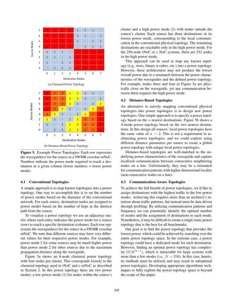
Figure 5. Example Power Topologies: Each row representsthe waveguide(s) for the source in a SWMR crossbar mNoC.Numbers indicate the power mode required to reach a des-tination in a given column (lower numbers = lower powermode).
4.1 Conventional TopologiesA simple approach is to map known topologies into a powertopology. One way to accomplish this is to set the numberof power modes based on the diameter of the conventionalnetwork. For each source, destination nodes are assigned topower modes based on the number of hops in the shortestpath from the source.
To visualize a power topology we use an adjacency ma-trix where each entry indicates the power mode for a source(row) to reach a specific destination (column). Each row rep-resents the waveguide(s) for the source in a SWMR crossbarmNoC. We note that different sources may have very differ-ent values for their respective power modes. For example,power mode 2 for some sources may be much higher powerthan power mode 2 for other sources due to the maximumpropagation distance along the waveguide.
Figure 5a shows an 8-node clustered power topologywith four nodes per cluster. This corresponds loosely to theclustered topology used in rNoC and c mNoC as describedin Section 2. In this power topology there are two powermodes: a low power mode (1) for nodes within the source’s
cluster and a high power mode (2) with nodes outside thesource’s cluster. Each source has three destinations in itslowest power mode, corresponding to the local communi-cation in the conventional physical topology. The remainingdestinations are reachable only in the high power mode. Forthe 256-node rNoC or c NoC systems, there are 252 nodesin the high power mode.
This approach can be used to map any known topol-ogy (e.g., trees, binary n-cubes, etc.) into a power topology.However, these architectures may not produce the lowestoverall power due to a mismatch between the power charac-teristics of the waveguides and the defined power topology.For example, nodes three and four in Figure 5a are phys-ically close on the waveguide, yet any communication be-tween them requires the high power mode.
4.2 Distance-Based TopologiesAn alternative to naively mapping conventional physicaltopologies into power topologies is to design new powertopologies. One simple approach is to specify a power topol-ogy based on the n nearest destinations. Figure 5b shows a4-mode power topology based on the two nearest destina-tions. In this design all sources’ local power topologies havethe same value of n = 2. This is not a requirement in ar-chitecting power topologies, and we could explore usingdifferent distance parameters per source to create a globalpower topology with unique local power topologies.
Distance-based topologies are well-matched to the un-derlying power characteristics of the waveguide and capturelocalized communication between consecutive neighboringnodes on a line. Unfortunately, they may be a mismatchfor communication patterns with higher dimensional locality(non-consecutive nodes on a line).
4.3 Communication-Aware TopologiesTo achieve the full benefit of power topologies, we’d like toassign destinations with the highest traffic to the low powermodes. Achieving this requires more than an architect’s in-tuition about traffic patterns, but instead must be data driventhrough profiling. By utilizing communication patterns andfrequency we can potentially identify the optimal numberof modes and the assignment of destinations to each mode.Nonetheless, it may be difficult to create a single static powertopology that is the best for all benchmarks.
Our goal is to find the power topology that provides thelowest power, which could be achieved by searching over theentire power topology space. In the extreme case, a powertopology could have a dedicated mode for each destination.However, finding an optimal power topology has complex-ity O(MN−1), which is intractable for large systems withmore than a few modes (i.e., N = 256). In this case, heuris-tic methods must be utilized, and may result in suboptimalpower topologies. Developing appropriate algorithmic tech-niques to fully explore the power topology space is beyondthe scope of this paper.
288

0
0.1
0.2
0.3
0.4
0.5
0.6
0.7
0.8
0.9
1
0 50 100 150 200 250
No
rm
ali
ze
d P
ow
er
Source Core Position
Figure 6. mNoC Single-Mode Power Profile
We explore communication-aware power topologies withtwo and four modes. In general, we apply the “more is less,less is more” philosophy and sort the destinations by com-munication frequency with the source. For the two-modecase, we iterate over all possible binary partitions of thesorted destinations into the two power modes to createN−2two mode power topologies. Starting with only the highestfrequency destination in the low power mode, we then pro-gressively move destinations to the low power mode untilonly the lowest frequency destination is in the high powermode. We then choose the power topology with the lowestoverall power.
For the four-mode case we apply various ad hoc heuris-tics to assign destinations from the sorted list to the fourpower modes. We consider several partitions of the sorteddestinations into the four modes, such as {64,64,64,63},{1,1,2,251}, {4,120,53,78}, but found the latter to be best,based on manual greedy assignment. We leave a methodicalexploration of this space to future work.
Application specific power topologies can be created byapplying the above methods to a single application. Thiscould be important for embedded or high-performance ASICdesigns where there are limited and well-known usage sce-narios. We also note that even the distance-based powertopologies could potentially benefit from more accurate in-formation on communication frequency since it might im-pact splitter design, as discussed previously.
4.4 Thread MappingThe base mNoC power topology operates by having eachsource broadcast a packet on its dedicated waveguide(s) andeach node locally determine if it is the destination. Thissingle mode topology provides the maximum connectivity:each source can reach all destinations. However, even inthis single-mode topology, different source nodes can re-quire different power. Consider the serpentine waveguidelayout where all waveguides terminate in the same regionsof the chip. For this layout, source nodes occupy locationson their respective waveguide that range from either end ofthe waveguide to the middle of the waveguide. The nodes inthe middle do not require as much source power as the end
(a) Naive Mapping (b) QAP MappingColor indicates communication intensity (dark = high, light = low)
(c) Naive 2-mode Power Topology (d) QAP 2-mode Power TopologyColor indicates power mode (dark = low, light = high). Each row
represents the waveguide(s) for a source node in a SWMRcrossbar. Note the non-contiguous destinations in each power
mode.
Figure 7. Thread Mapping and Power Topologies (wa-ter spatial). Rows are sources and columns are destinations.
nodes since their signals propagate only half the distance asthe end node signals.
The variation in required source power creates a powerprofile for the overall crossbar. Although each source hasa single fixed power, the power for each source dependson its location (see Figure 6). Given this power profile andthe observation of workload communication locality, it isbeneficial to map frequently communicating threads to thecores located near the center of the waveguide.
Even for different layouts where waveguides terminatein different regions of the chip, a power profile still exists.Cores are arranged in a 2D plane, even a more complexlayout of waveguides cannot create a uniform distance fromeach source to each destination.
Thread mapping can be achieved either offline or onlineif the workload runs long enough to warrant migration. Ourmapping problem is an instance of the quadratic assignmentproblem (QAP), which is NP-hard, therefore we use heuris-tic methods. We explore both Taboo [32] and simulated an-nealing [10], and find that Taboo generally performs best.
4.5 DiscussionFigure 7 shows the communication pattern for the wa-ter spatial benchmark before (Figure 7a) and after runningTaboo (Figure 7b). Each row is a source node (thread) andeach column is a destination node, darker colors representa larger amount of communication. In contrast to the naive
289

Router pipeline stages 4 cyclesElectrical link latency 1 cyclesOptical link latency 1-9 cycles for mNoC; 1-5 for rNoCClock 5GHzFlit size 256-bit
Core modelin-order model, private 32KB L1D,32KB L1I, 512KB L2 Cache
Table 2. Simulation configuration
mapping, the new mapping has very high density commu-nication clustered around the middle nodes, which requirelower overall power than the nodes near the ends of thewaveguide.
Figure 7 also shows the mode assignment for a 2-modepower topology specific to water spatial before (Figure 7c)and after running Taboo (Figure 7d). Each row represents asource node’s waveguide(s) and each column is a destina-tion node, a dark color indicates a specific destination node(x axis) is in the low power mode of a source node (y axis).We observe that this power topology matches the communi-cation patterns from Figure 7a and 7b, with more frequentlycommunicating nodes in the low power mode. These figuresalso show the non-uniform nature of communication-awarepower topologies: source nodes have different local powertopologies, and the general framework does not require con-secutive destinations within a given power mode.
In this paper we perform thread mapping based on the sin-gle mode power topology and thus the assignment accountsfor only the waveguide loss between a source and destina-tion. A more general approach would perform a joint opti-mization of power topology design and thread mapping. Weleave exploring additional heuristic techniques to performthis even more complex assignment as future research.
5. EvaluationIn this section, we evaluate the power consumption of mNoCfor various power topologies, using naive and QAP threadmapping. Our results show that power topologies combinedwith QAP thread mapping achieves the goal of performanceequal to a full crossbar, but with power consumption closeto the smaller clustered topology. Thread mapping is criticalfor achieving this goal, where two power modes capture asignificant fraction of the opportunity (46% reduction), but a4-mode power topology can provide an additional 5% reduc-tion. We first present our evaluation methodology and thendiscuss the impact on power consumption of several differ-ent design options. The options include naive distance-basedpower topology, thread mapping, communication-awarepower topologies, and application-specific power topolo-gies.
QD LED energy efficiency 10%
QD LED 1-to-0 ratio 1Waveguide loss 1dB/cm
Coupler loss 1dB
Photodetector mIOP 10µW
Power loss of chromophores 5µW for 10µW mIOPOptical splitter 0.2dB
Table 3. Optical energy parameters
5.1 MethodologyWe create our mNoC topology in the Graphite [25] simula-tor and run all the simulations in full simulator mode. Weexplore 256-core systems and the simulation configurationis summarized in Table 2. We use the MOSI directory-basedcache coherence protocol provided in Graphite along with itsbuilt-in models for contention in the system. The total O/Eand E/O latency is about 200 ps and is modeled as 1 cycle inthe nanophotonic link traversal time. We assume a die size of400mm2, therefore the waveguide’s total length is approxi-mately 18cm. We conservatively assume the speed of lightin the waveguide is about 10cm/ns, which means 1.8ns totravel the longest distance, corresponding to a worst case of9 cycles for a 5GHz clock. All electrical links are modeledas 1 cycle [8] for the rNoC and clustered mNoC (c mNoC).
We run 12 benchmarks from the SPLASH benchmarksuite [37] to evaluate performance. As mentioned in Sec-tion 2, a SWMR single-mode mNoC crossbar improves theperformance by 10% compared with rNoC, while c mNoChas similar performance to rNoC. To evaluate power con-sumption, we obtain traces of communication packets fromall 12 benchmarks executing on mNoC and build a powermodel to explore the impact of power topologies and threadmapping on power consumption. The key parameters usedin the power model are shown in Table 3. The baseline forcomparison is total network power for a 256 × 256 singlemode mNoC with naive thread mapping, shown in Table 4.For rNoC we calculate power using similar methodology toPang et al. [30]; however we bias in favor of rNoC by us-ing 0.1µW for photodetector mIOP vs. the 10µW mIOPfor mNoC as descrbied in 2.2. We further bias results to-ward rNoC by assuming 10% QD LED efficiency insteadof the 18% assumed in [30]. The electrical buffer power isdeteremined using models decribed by others [19, 27, 28]which may slightly bias in favor of mNoC due to our in-creased number of buffers.
Our baseline results reveal that the clustered rNoC (radix-64 optical crossbar) consumes 36W, with 23W in ring trim-ming and a 5W laser source, lower than previous results [27,36] for SWMR optical crossbars (see Figure 10 in Sec-tion 5.7 for a complete breakdown). The average powerfor the base mNoC is 20.94W, lower than the clusteredrNoC. Furthermore, mNoC is energy proportional, appli-cations with higher network utilization (e.g., radix) require
290

Benchmark Power (W) Benchmark Power (W)barnes 7.05 water s 5.28radix 120.34 water ns 6.08
ocean c 12.31 cholesky 5.14ocean nc 24.23 lu cb 7.79raytrace 3.99 lu ncb 43.70
fft 11.41 volrend 3.99average 20.94
Table 4. Base mNoC Power Consumption
Symbol DefinitionM ModeT Thread mapping with QAPN Naive distance-based mode assignmentG General mode assignment based on sampled weightsC Custom power topology designU Uniform traffic pattern for splitter designW Weighted traffic pattern for splitter designS Sampled traffic weights for splitter design
Table 5. Design Symbols
high power (> 100W); however we show that power awarethread mapping and power topologies reduce this belowrNoC, to ∼ 20W, while maintaining the performance ben-efits of high-radix crossbars. We use the symbols shown inTable 5 to create a notation for the various power topolo-gies in our figures; for example, 2M T N S4 means 2 modes,QAP thread mapping, naive distance-based, and splitter de-sign based on weights from sampling 4 applications.
5.2 Naive Distance-Based Power TopologiesWe evaluate two distance-based power topologies: 1) a 2-mode topology with the 128 closest destinations assignedto the low power mode of a source, and the remaining des-tinations assigned to the higher power mode, and 2) a 4-mode power topology based on groups of 64 nearest nodes.To calculate overall source power (Equation 1), and thecorresponding splitter design, we explored several commu-nication weightings (e.g., 66% / 33%, uniform, etc.) andfound qualitatively similar results across all weightings (seeSection 5.6). For clarity we only present results for uni-form weights. Figure 8 shows the power consumption of thetwo distance-based power topologies with naive and QAPthread mapping normalized to the single-mode mNoC withnaive thread mapping (1M). Here we consider only the naivethread mapping, we discuss QAP thread mapping below.The 4-mode distance-based power topology reduces the to-tal mNoC power by 12% while the 2-mode distance-basedpower topology reduces power by 10% on average (har-monic mean). Ocean nc and radix show the largest benefitsof power topologies with reductions 15%-20%. We also im-plement 256-node clustered 2-mode power topology similar
to Fig. 5a with naive thread mapping; however it only re-duces mNoC power by 1% on average, demonstrating thatdistance-based power topologies are superior to clusteredpower topologies.
5.3 Impact of Thread MappingClustering communication so that frequently communicat-ing threads are allocated to cores near the center of thewaveguide provides greater opportunity to exploit the differ-ent power modes in a given power topology. Figure 8 sup-ports this hypothesis; QAP thread mapping helps all threepower topologies. The average power reductions over thebase mNoC are 27%, 38%, and 39% for the 1-mode, 2-mode, and 4-mode power topologies, respectively. Ocean ncand radix show the most improvement from QAP threadmapping with power topologies providing as low as 26%-32% of total network power vs. the base single-mode mNoCpower topology. Although QAP thread mapping has largerimpact on total mNoC power than power topologies alone,the best overall design uses a 4-mode power topology alongwith QAP thread mapping.
5.4 Communication-Aware Mode AssignmentCommunication-aware power mode assignment follows the“more is less, less is more” philosophy by utilizing commu-nication information from benchmarks. We first sort all thedestination nodes according the communication frequencywith a given source node and then assign more frequent des-tinations to lower power mode and less frequent destinationsto higher power modes. In this section we explore two meth-ods for obtaining communication frequency: sampling fromfour benchmarks (lu cb, radix, raytrace, water s) and aver-aging across all 12 benchmarks. A more statistically signif-icant exploration of sampling, while interesting, is beyondthe scope of this paper.
To isolate the impact of communication-aware mode as-signment, we compare to a distance-based power topologythat uses the sampled traffic for splitter design. Therefore,the difference in total mNoC power is mainly due to differ-ent mode assignment. As shown in Fig. 9, communication-aware mode assignment generally works better than naivedistance-based mode assignment. Using weights from theaverage of all 12 benchmarks reduces power by 7% com-pared with the distance-based mode assignment for the 2-mode design. The reduction is increased to 10% for the4-mode design. Moreover, communication-aware mode as-signment based on the average of 12 benchmarks works bet-ter than the one based on 4 sampled benchmarks. As ex-pected, when more communication information is available,the better the design.
A 4-mode power topology produces qualitatively simi-lar results, but quantitatively is the best overall design whensampling across all 12 benchmarks with 49% of the basemNoC’s power on average vs. 53% for the 2-mode powertopology. Compared to the best distance-based power topol-
291

0
0.2
0.4
0.6
0.8
1
barnes radix ocean_c ocean_nc raytrace 7 water_s water_ns cholesky lu_c lu_nc volrend average
Normalized
mNoC
Pow
er
1M 1M_T 2M_N_U 2M_T_N_U 4M_N_U 4M_T_N_U
Figure 8. Distance-Based Power Topology With and Without Thread Mapping
0 0.1 0.2 0.3 0.4 0.5 0.6 0.7 0.8 0.9 1
barnes radix ocean_c ocean_nc raytrace ; water_s water_ns cholesky lu_c lu_nc volrend average
Normalized
mNoC
Pow
er
1M 2M_T_N_S4 2M_T_G_S4 2M_T_N_S12 2M_T_G_S12
(a) Two-Mode Power Topologies
0 0.1 0.2 0.3 0.4 0.5 0.6 0.7 0.8 0.9 1
barnes radix ocean_c ocean_nc raytrace ; water_s water_ns cholesky lu_c lu_nc volrend average
Normalized
mNoC
Pow
er
1M 4M_T_N_S4 4M_T_G_S4 4M_T_N_S12 4M_T_G_S12
(b) Four-Mode Power Topologies
Figure 9. Communication-Aware Mode Designs vs Distance-Based Mode Designs
ogy that uses the uniform traffic for splitter design in Fig. 8,the best 4-mode power topology with communication-awaremode assignment reduces the total mNoC power by 12%.This demonstrates the benefit of communication awarepower topologies.
5.5 Application Specific DesignsTo understand how well the various general power topolo-gies work, we create application specific power topologiestailored to each benchmark. We examine the source powerconsumption for the application specific designs with QAPthread mapping and naive mapping. They both have similarcharacteristics, but do not have a significant improvementover naive distance-based power topologies (about 8%). The“keep it simple” design philosophy may apply. However, forembedded systems or situations with known specific com-
munication patterns, a custom power topology may be ben-eficial.
5.6 Splitter Design Sensitivity AnalysisAs explained in Section 3.2 and Section 4.3, the commu-nication patterns of benchmarks could potentially affect thesplitter design. We evaluated the sensitivity of splitter designto communication traffic weights using the application spe-cific 2-mode power topology with QAP thread mapping asthe basic design. The different communication weights weconsider are: uniform, 66%/33%, 33%/66%, samples from 4benchmarks (S4), and the average across all 12 benchmarks(S12).
Our results reveal minimal variation in power reductionacross the different weights (within 2%), but all produceover a 40% reduction in total mNoC power on average. Onepotential explanation for this limited impact of weights on
292

0
0.1
0.2
0.3
0.4
0.5
0.6
0.7
0.8
0.9
1
rNoC mNoC c_mNoC PT_mNoC
En
erg
y C
on
sum
pti
on
Re
lati
ve
to
rN
oC
Ring Heating Source Power O/E&E/O Elink and Router
Figure 10. Total NoC Energy Consumption
splitter designs is that the total source power for given asource core is a function of both weights and splitter ratios.Changes in the weights can be compensated by changes inthe splitter ratios resulting in similar overall power. There-fore, the traffic pattern, as it relates to splitter design, hasminimal impact on overall power consumption.
5.7 Overall mNoC Energy ConsumptionAs mentioned in Section 2.2, our goal is to design a singlephysical network with the same performance as the high-radix mNoC, but with the power savings of the lower-radixclustered topology (c mNoC). Figure 10 shows the total en-ergy normalized to rNoC for baseline (mNoC), c mNoC, andthe best power topology mNoC (PT mNoC=4M T G S12)with static splitters. The power model for rNoC is similarto the one proposed by Joshi et al. [19]. We use 20µW /ringover 20K temperature range as thermal tuning power to fa-vor rNoC. More accurate ring models [26, 39] indicate muchhigher ring tuning power. Since the dominant power forrNoC is ring tuning instead of O/E, it shows little or nobenefit to increase mIOP for rNoC (see Section 2.2). There-fore, we keep rNoC’s photodetector mIOP as 1µW insteadof 10µW used by all mNoC related topologies. From theseresults we see that the best power topology with thread map-ping requires only 28% of rNoC’s energy, close to the 21%required by c mNoC and much lower than the base mNoC(1M power topology) of 57%. Note that c mNoC has smallersource and OE/EO power than mNoC, because the lowerradix requires shorter waveguide length and fewer opticaldevices.
Our power topology has at least the same performance asthe base radix-256 mNoC (1M). Performance could be im-proved by considering QAP thread mapping, because it re-duces the distance between source and destination, and po-tentially reduces latency. Thread mapping will have mini-mal impact on rNoC’s power consumption since it is dom-inated by thermal ring tuning. Similarly, c mNoC’s poweris dominated by electrical components. There may be someimpact on performance of the clustered topologies (rNoCand c NoC) by thread mapping, however only three nodesare near neighbors and communication with all others re-
quires traversal of two local routers and the larger crossbar.Therefore, we don’t expect to observe too much benefit fromthread mapping, nonetheless, we are currently exploring thisdesign point.
6. Related WorkWe discuss related work based on three broad categories:current nanophotonic NoC designs, power optimization inboth on-chip networks and wireless networks, and threadmapping methods to optimize the network in terms of en-ergy, performance or congestion in NoCs. Although differentpower optimization methods have been proposed for on-chipnetworks, the concepts proposed in this paper such as logicalpower mode and power topology in nanophotonic NoCs arenew.
Bus-based crossbars are very popular in the currentnanophotonic NoCs. A typical nanophotonic crossbar is usu-ally designed using one of the following structures: Multi-Write-Single-Read (MWSR) as proposed for Corona [36],Single-Write-Multi-Read (SWMR) shared-bus crossbar pro-posed by Kirman et al. [21] and Pan et al. [28], or Multi-Write-Multi-Read (MWMR) which combines the above twoand proposes a reduced number of channels design as pro-posed for Flexishare [27]. However, due to the power in-efficiency from the off-chip laser source and thermal ringtuning power, and the ring resonator’s nonlinearity, thesedesigns are difficult to scale to more than radix-64. Nitta etal. [26] presents a thermal model to calculate the ring tuningpower, which is much bigger than the heating power calcu-lated with the popular per ring fixed cost method. Even withfurther optimization techniques [39], the ring power con-sumption is still a dominant factor. Other topologies basedon ring resonator switches are also explored, such as a 2Dgrid NoC from Phastlane [9] and a torus-based hierarchi-cal hybrid NoC called THOE [41]. Xue et al. [40] proposesa freespace optical interconnect that uses VCSELs as lightsources.
As power becomes a larger concern in current computingsystems, various power optimization methods are proposedfor on-chip networks. Recent work from Koka et al. [22]presents a power constrained method for designing and eval-uating the nanophotonic interconnects. Their results showthat under reasonable device assumptions for a given in-put optical power, point-to-point networks have better powerand performance characteristics than switched-based net-works. Catnap [11] proposes a power proportional NoC de-sign which divides a single NoC into multiple subnetworksto exploit the benefits of power gating. We could applythis same method on mNoC by deactivating waveguides persource to decrease bandwidth and reduce power. Other workexplores different physical topologies to reduce NoC energyand/or latency [12, 17, 18]. Finally, any transmission line orwireless communication system can utilize the same prin-
293

ciples of power modes based on distance to destinations,e.g., [2, 7].
Thread mapping is previously used to design energyand/or latency-aware on-chip networks. Hu et al. [16] pro-poses an efficient branch-and-bound algorithm to map coresto a regular tile-based network to save total energy. Hoe-fler et al. [15] discusses efficient application communicationpattern mapping to sparse network topologies. They demon-strate a heuristic method based on graph similarity to reducenetwork congestion and also improve application communi-cation performance. Their methods could potentially be usedfor joint optimization of thread mapping and power topologydesign.
7. ConclusionEnergy efficiency and power dissipation are increasingly im-portant design goals for computer systems. Manycore pro-cessors exacerbate this problem since on-chip interconnect(NoC) can become a significant portion of overall powerconsumption. This paper utilizes a new molecular-scale pho-tonic NoC technology (mNoC) and shows how to architectpower efficient designs through the use of power topologies.A power topology is a set of power modes and an assign-ment of destination nodes reachable in these power modes,for each source node in the system. Power topology im-plementations are enabled by careful waveguide design andthe unique mNoC capability of current-controlled on-chipQD LEDs for light sources.
The benefits of mNoC power topologies include scalingto high-radix crossbars, to achieve high performance, whileproviding power savings close to smaller-radix crossbars.We present several different power topologies for a 256-coresystem with two and four power modes, including distance-based and communication-aware topologies that reduce net-work power by ≥ 10% compared to a baseline mNoC witha single power mode that can reach all destinations. Furtherimprovements, additional 40% reduction, are possible withintelligent thread mapping that maps frequently communi-cating threads to cores with lower power communication re-quirements. We find that distance-based power topologiescapture a significant fraction of the overall benefit in mNoCpower reduction 40%, but that utilizing application informa-tion for mode assignment can achieve over a 50% reduction.Overall, mNoC with power topologies achieves performance10% higher than a clustered ring-resonator photonic NoC,while reducing energy by 72%.
The work in this paper represents our initial efforts atexploiting emerging molecular-scale photonics to architectnovel power efficient on-chip interconnects. The designspace is very large, and we’ve explored only a small por-tion. Areas of future work include, but are not limited to:dynamic power modes, joint optimization of thread map-ping and power topology design, applying power topologiesto embedded systems with well-defined IP blocks and com-
munication patterns, and exploring mNoC’s ability to multi-cast/broadcast when used in coherence protocol design.
AcknowledgementsThis material is based upon work supported by, or in part by,the National Science Foundation (CCF-0702434), the De-fense Advanced Research Projects Agency and the U. S.Army Research Office under grant number W911NF-13-1-0096 (Distribution Statement A: Approved for Public Re-lease, Distribution Unlimited). The views, opinions, and/orfindings contained in this article are those of the author(s)and should not be interpreted as representing the officialviews or policies of the Department of Defense or the U.S.Government. We thank the anonymous reviewers and theDuke self-assembled systems group for their comments thatimproved the quality of the paper.
Appendix AFor a N × N crossbar, to solve for Sj at the destination jgiven a source node i, where i, j ∈ {0..N − 1}, we buildon the observation that destination nodes unique to a givenpower mode m ∈ {0..M} have the same βj values whichwe call γm: βi = βj = γm,∀i, j ∈Mdestm −Mdestm−1,and for each source mode power Pmodek, k ∈ {0..M} wedefine unique γk,m. We then further simplify by defining allγk,m in terms of γ0,m in power mode 0 to obtain αm =γ0,m,m ∈ {0..M}, where αm ∈ (0..1], α0 = 1.
Equations 3-6 show abbreviated versions of Equation 2for a four mode(M = 4) power topology, which connectEquation 2 to Equation 1. The equations are based on an ob-servation that given a fabricated waveguide, a given sourcepower is proportional to any destination’s received power,and that a change in the source power results in a propor-tional change in all destination’s received power.
Pmode0 = f(Pmin, α1Pmin, α2Pmin, α3Pmin) (3)
Pmode1 = f(1
α1Pmin, Pmin,
α2
α1Pmin,
α3
α1Pmin) (4)
Pmode2 = f(1
α2Pmin,
α1
α2Pmin, Pmin,
α3
α2Pmin) (5)
Pmode3 = f(1
α3Pmin,
α1
α3Pmin,
α2
α3Pmin, Pmin) (6)
We can then rearrange the summand of Equation 2 toexpress Sj in terms of αm, Pmin,& L. We then iterate overall αm from 0 to 1 in increments of 0.1 to obtain values foreach power mode.
Note that by determining the values that minimizePmode0,all higher power modes can be computed by Pmodei =Pmode0αi
. Once we have the alpha values we can substituteinto the splitter equation to obtain the appropriate splittervalues for use in fabrication. Since we have one equationwith many unknowns, we solve for alpha values computa-tionally by iterating over all alpha values (better results maybe achieved by using steps smaller than 0.1).
294
References[1] R. Arians, A. Gust, T. Kummell, C. Kruse, S. Zaitsev,
G. Bacher, and D. Hommel. Electrically driven single quan-tum dot emitter operating at room temperature. AppliedPhysics Letters, 93(17):173506–173506, 2008.
[2] Wonseok Baek, David SL Wei, and C-CJ Kuo. Power-awaretopology control for wireless ad-hoc networks. In WirelessCommunications and Networking Conference, 2006. WCNC2006. IEEE, volume 1, pages 406–412. IEEE, 2006.
[3] N. Barrow-Williams, C. Fensch, and S. Moore. A commu-nication characterisation of splash-2 and parsec. In Work-load Characterization, 2009. IISWC 2009. IEEE InternationalSymposium on, pages 86–97. IEEE, 2009.
[4] Valeriu Beiu, Jose M Quintana, and Marıa J Avedillo. Vlsiimplementations of threshold logic-a comprehensive survey.Neural Networks, IEEE Transactions on, 14(5):1217–1243,2003.
[5] A. Biberman, K. Preston, G. Hendry, N. Sherwood-Droz,J. Chan, J.S. Levy, M. Lipson, and K. Bergman. Photonicnetwork-on-chip architectures using multilayer deposited sil-icon materials for high-performance chip multiprocessors.ACM Journal on Emerging Technologies in Computing Sys-tems (JETC), 7(2):7, 2011.
[6] J. Chan, G. Hendry, K. Bergman, and L.P. Carloni. Physical-layer modeling and system-level design of chip-scale pho-tonic interconnection networks. Computer-Aided Designof Integrated Circuits and Systems, IEEE Transactions on,30(10):1507–1520, 2011.
[7] Benjie Chen, Kyle Jamieson, Hari Balakrishnan, and RobertMorris. Span: An energy-efficient coordination algorithmfor topology maintenance in ad hoc wireless networks. InProceedings of the 7th annual international conference onMobile computing and networking, pages 85–96. ACM, 2001.
[8] G. Chen, H. Chen, M. Haurylau, N.A. Nelson, D.H. Albonesi,P.M. Fauchet, and E.G. Friedman. Predictions of cmos com-patible on-chip optical interconnect. Integration, the VLSIjournal, 40(4):434–446, 2007.
[9] M.J. Cianchetti, J.C. Kerekes, and D.H. Albonesi. Phastlane:a rapid transit optical routing network. In 36th annual interna-tional symposium on Computer architecture, pages 441–450,2009.
[10] David T Connolly. An improved annealing scheme for theqap. European Journal of Operational Research, 46(1):93–100, 1990.
[11] Reetuparna Das, Satish Narayanasamy, Sudhir K Satpathy,and Ronald G Dreslinski. Catnap: Energy proportional multi-ple network-on-chip. In to appear in Proceeding of the 40thannual international symposium on Computer architecture,2013.
[12] Haytham Elmiligi, Ahmed A Morgan, M Watheq El-Kharashi,and Fayez Gebali. Power-aware topology optimization fornetworks-on-chips. In Circuits and Systems, 2008. ISCAS2008. IEEE International Symposium on, pages 360–363.IEEE, 2008.
[13] Ashwini Gopal, Kazunori Hoshino, Sunmin Kim, and Xiao-jing Zhang. Multi-color colloidal quantum dot based light
emitting diodes micropatterned on silicon hole transportinglayers. Nanotechnology, 20(23):235201, 2009.
[14] F Hargart, CA Kessler, T Schwarzback, E Koroknay, S Wei-denfeld, M Jetter, and P Michler. Electrically driven quantumdot single-photon source at 2 ghz excitation repetition ratewith ultra-low emission time jitter. Applied Physics Letters,102(1):011126–011126, 2013.
[15] Torsten Hoefler and Marc Snir. Generic topology mappingstrategies for large-scale parallel architectures. In Proceedingsof the international conference on Supercomputing, pages 75–84. ACM, 2011.
[16] Jingcao Hu and Radu Marculescu. Energy-aware mapping fortile-based noc architectures under performance constraints.In Design Automation Conference, 2003. Proceedings of theASP-DAC 2003. Asia and South Pacific, pages 233–239.IEEE, 2003.
[17] Yuanfang Hu, Hongyu Chen, Yi Zhu, Andrew A Chien, andChung-Kuan Cheng. Physical synthesis of energy-efficientnetworks-on-chip through topology exploration and wire styleoptimization. In Computer Design: VLSI in Computers andProcessors, 2005. ICCD 2005. Proceedings. 2005 IEEE In-ternational Conference on, pages 111–118. IEEE, 2005.
[18] Yuanfang Hu, Yi Zhu, Hongyu Chen, Ronald Graham, andChung-Kuan Cheng. Communication latency aware lowpower noc synthesis. In Proceedings of the 43rd annual De-sign Automation Conference, pages 574–579. ACM, 2006.
[19] A. Joshi, C. Batten, Y.J. Kwon, S. Beamer, I. Shamim,K. Asanovic, and V. Stojanovic. Silicon-photonic clos net-works for global on-chip communication. In Proceedingsof the 2009 3rd ACM/IEEE International Symposium onNetworks-on-Chip, pages 124–133. IEEE Computer Society,2009.
[20] Pawan Kapur. Scaling induced performance chal-lenges/limitations of on-chip metal interconnects andcomparisons with optical interconnects. Ph.D. Dissertation,Stanford University, Stanford, California, 2002.
[21] N. Kirman, M. Kirman, R.K. Dokania, J.F. Martinez, A.B.Apsel, M.A. Watkins, and D.H. Albonesi. Leveraging opticaltechnology in future bus-based chip multiprocessors. In Pro-ceedings of the 39th Annual IEEE/ACM International Sympo-sium on Microarchitecture, pages 492–503. IEEE ComputerSociety, 2006.
[22] Pranay Koka, Michael O McCracken, Herb Schwetman, Chia-Hsin Owen Chen, Xuezhe Zheng, Ron Ho, Kannan Raj, andAshok V Krishnamoorthy. A micro-architectural analysis ofswitched photonic multi-chip interconnects. In Proceedings ofthe 39th International Symposium on Computer Architecture,pages 153–164. IEEE Press, 2012.
[23] J.R. Lakowicz. Principles of fluorescence spectroscopy, vol-ume 1. Springer, 2006.
[24] Benjamin S Mashford, Matthew Stevenson, Zoran Popovic,Charles Hamilton, Zhaoqun Zhou, Craig Breen, JonathanSteckel, Vladimir Bulovic, Moungi Bawendi, Seth Coe-Sullivan, et al. High-efficiency quantum-dot light-emittingdevices with enhanced charge injection. Nature Photonics,7(5):407–412, 2013.
295

[25] J.E. Miller, H. Kasture, G. Kurian, C. Gruenwald, N. Beck-mann, C. Celio, J. Eastep, and A. Agarwal. Graphite: A dis-tributed parallel simulator for multicores. In High Perfor-mance Computer Architecture (HPCA), 2010 IEEE 16th In-ternational Symposium on, pages 1–12. IEEE, 2010.
[26] Christopher Nitta, Matthew Farrens, and Venkatesh Akella.Addressing system-level trimming issues in on-chip nanopho-tonic networks. In High Performance Computer Architecture(HPCA), 2011 IEEE 17th International Symposium on, pages122–131. IEEE, 2011.
[27] Y. Pan, J. Kim, and G. Memik. Flexishare: Channel sharingfor an energy-efficient nanophotonic crossbar. In High Perfor-mance Computer Architecture (HPCA), 2010 IEEE 16th Inter-national Symposium on, pages 1–12. IEEE, 2010.
[28] Yan Pan, Prabhat Kumar, John Kim, Gokhan Memik,Yu Zhang, and Alok Choudhary. Firefly: Illuminating futurenetwork-on-chip with nanophotonics. In In Proc. of the Inter-national Symposium on Computer Architecture, 2009.
[29] Jun Pang, Christopher Dwyer, and Alvin R Lebeck. Exploit-ing emerging technologies for nanoscale photonic networks-on-chip. In Proceedings of the Sixth International Workshopon Network on Chip Architectures, pages 53–58. ACM, 2013.
[30] Jun Pang, Christopher Dwyer, and Alvin R. Lebeck. mNoC:Large nanophotonic network-on-chip crossbars with molecu-lar scale devices. ACM Journal on Emerging Technologies inComputing Systems (JETC), to appear.
[31] I.K. Park, M.K. Kwon, J.O. Kim, S.B. Seo, J.Y. Kim, J.H.Lim, S.J. Park, and Y.S. Kim. Green light-emitting diodeswith self-assembled in-rich ingan quantum dots. AppliedPhysics Letters, 91:133105, 2007.
[32] E Taillard. Robust taboo search for the quadratic assignmentproblem. Parallel computing, 17(4):443–455, 1991.
[33] Dmitri V Talapin and Jonathan Steckel. Quantum dot light-emitting devices. Mrs Bulletin, 38(09):685–691, 2013.
[34] Limin Tong, Rafael R Gattass, Jonathan B Ashcom, Sail-ing He, Jingyi Lou, Mengyan Shen, Iva Maxwell, and EricMazur. Subwavelength-diameter silica wires for low-loss op-tical wave guiding. Nature, 426(6968):816–819, 2003.
[35] Bernard Valeur et al. Molecular fluorescence: principles andapplications. John Wiley & Sons, 2013.
[36] Dana Vantrease, Robert Schreiber, Matteo Monchiero, MorayMcLaren, Norman P. Jouppi, Marco Fiorentino, Al Davis,Nathan Binkert, Raymond G. Beausoleil, and Jung Ho Ahn.Corona: System implications of emerging nanophotonic tech-nology. In Proceedings of the 35th Annual International Sym-posium on Computer Architecture, pages 153–164, Washing-ton, DC, USA, 2008. IEEE Computer Society.
[37] Steven Cameron Woo, Moriyoshi Ohara, Evan Torrie,Jaswinder Pal Singh, and Anoop Gupta. The splash-2 pro-grams: characterization and methodological considerations.In Proceedings of the 22nd annual international symposiumon Computer architecture, pages 24–36. ACM, 1995.
[38] V. Wood and V. Bulovic. Colloidal quantum dot light-emittingdevices. Nano Reviews, 1(0), 2010.
[39] Yi Xu, Jun Yang, and Rami Melhem. Tolerating process vari-ations in nanophotonic on-chip networks. In Proceedings ofthe 39th International Symposium on Computer Architecture,pages 142–152. IEEE Press, 2012.
[40] Jing Xue, Alok Garg, Berkehan Ciftcioglu, Jianyun Hu, ShangWang, Ioannis Savidis, Manish Jain, Rebecca Berman, PengLiu, Michael Huang, Hui Wu, Eby Friedman, Gary Wicks, andDuncan Moore. An intra-chip free-space optical interconnect.In Proceedings of the 37th Annual International Symposiumon Computer Architecture, ISCA ’10, pages 94–105, NewYork, NY, USA, 2010. ACM.
[41] Y. Ye, J. Xu, X. Wu, W. Zhang, W. Liu, and M. Nikdast.A torus-based hierarchical optical-electronic network-on-chipfor multiprocessor system-on-chip. ACM Journal on Emerg-ing Technologies in Computing Systems (JETC), 8(1):5, 2012.
296