Embed Size (px)
Citation preview

MOPEC 5000TM
AUTOPSY SAWUser Manual
INSTRUCTIONS FOR YOUR SAFETY
Please read carefully and retain for future reference. It is a requirement of IEC/EN 60601-1 that these instructions are made available to the operator and qualified maintenance staff at all times.
The Mopec 5000 System has been examined and found to be in compliance with the standard for Medical Electrical Equipment IEC/EN60601-1
www.mopec.com(800) 362-8491
CONTENTS
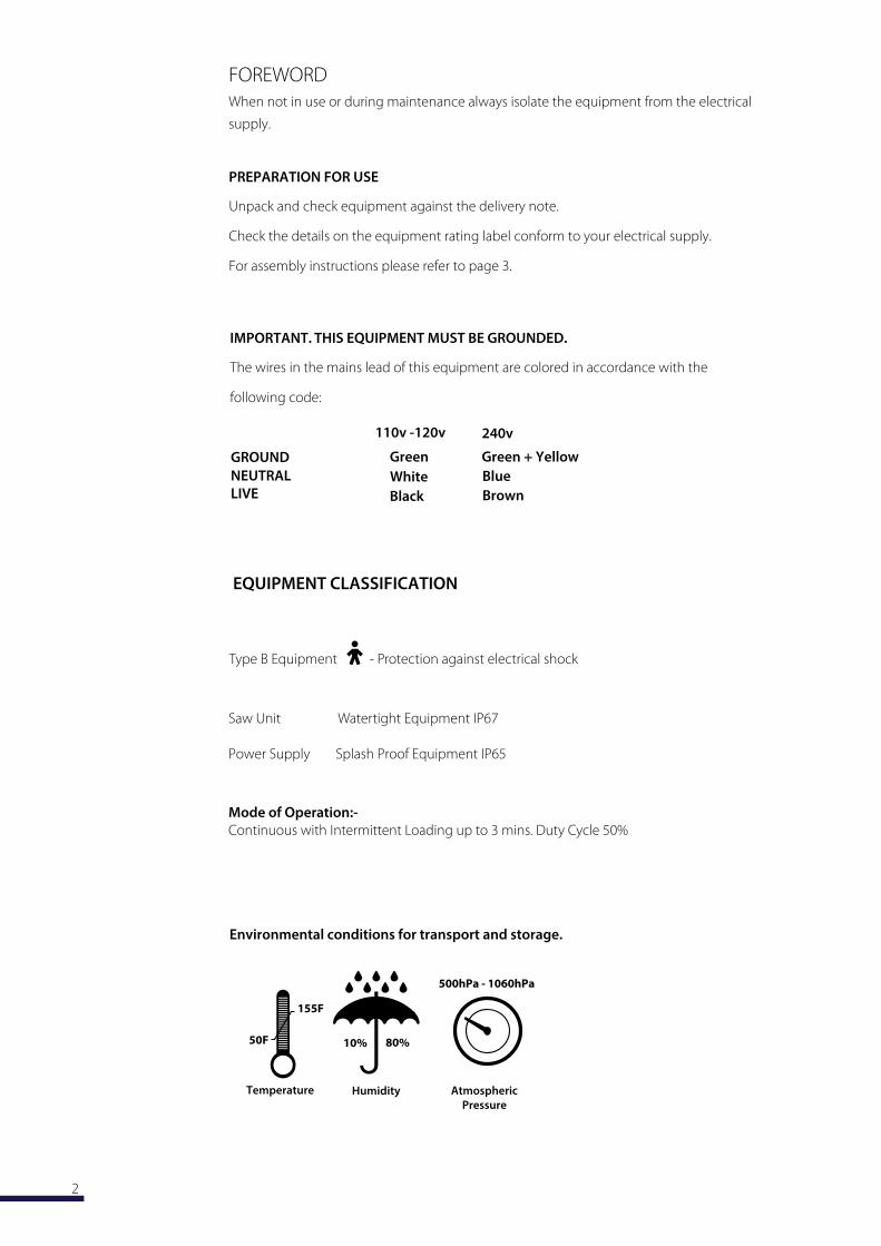
Type B Equipment - Protection against electrical shock
Saw Unit Watertight Equipment IP67
Power Supply Splash Proof Equipment IP65
EQUIPMENT CLASSIFICATION
Mode of Operation:-
Continuous with Intermittent Loading up to 3 mins. Duty Cycle 50%
3
GENERAL DESCRIPTION
The M 5000 Oscillating Saw has been developed to help minimize the risk of
cross infection in sensitive areas, providing it is used in accordance with the
manufacturer’s instructions.
The complete system comprises three basic units.
THE SAW UNIT
This unit is fed from the power supply. It is hermetically sealed allowing disinfection and
appropriate sterilization without dismantling. The enclosed motor cannot become
contami-nated , consequently there is no hazardous aerosol effect. All external materials
used in its construction are non corrosive.
THE FILTRATION UNIT
This unit is fed from the power supply. It gives highly efficient three stage filtration by way
of a paper filter, cloth filter and highly efficient cartridge filter (Hepa filter) respectively. It is
quite capable of filtering dry and partially damp material but must never be used to extract
liquids. This unit is not watertight and not designed for liquid extraction.
THE POWER SUPPLY
This unit is fed from the supply and in turn delivers the appropriate electrical cur-
rents to the saw unit and the vacuum filtration unit. The complete system is activated by
the momentary switch on the saw unit. An intelligent current limiting device (which resets
itself automatically) is incorporated in the power supply to prevent overload usage of the
saw unit. This unit is watertight.
User preference may require the equipment to be supplied in its basic form which
comprises the saw unit and power supply only. A filtration unit may be easily added by the
customer at a later stage.
The complete M 5000 system is capable of handling health endangering dusts,
making it suitable for use in hospitals and industrial environments where the collection
and disposal of such debris is subject to stringent control.
This equipment is not suitable for use in an environment where an explosion risk is present.
The equipment should only be moved by using the handle provided and never by
pulling on the saw unit or
SEQUENCE OF OPERATION
Warning: This equipment is designed for use by properly trained personnel only.
M accepts no liability whatsoever for inapp
1 Plug equipment into appropriate s . Check indicator on power
supply is lit.
2 depress and release the on/off button.
The complete system will then start.
3 Depress and release the on/off button once again and the system will then stop.
Always disconnect the equipment from the when not in use.
4
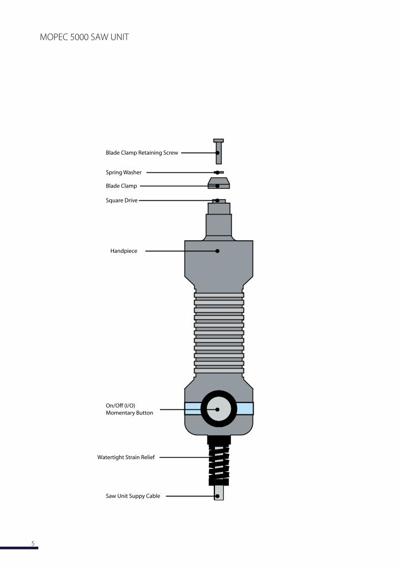
Blade Clamp Retaining Screw
Spring Washer
Blade Clamp
Square Drive
On/Off (I/O)
Momentary Button
Watertight
Saw Unit Suppy Cable
M 5000 SAW UNIT
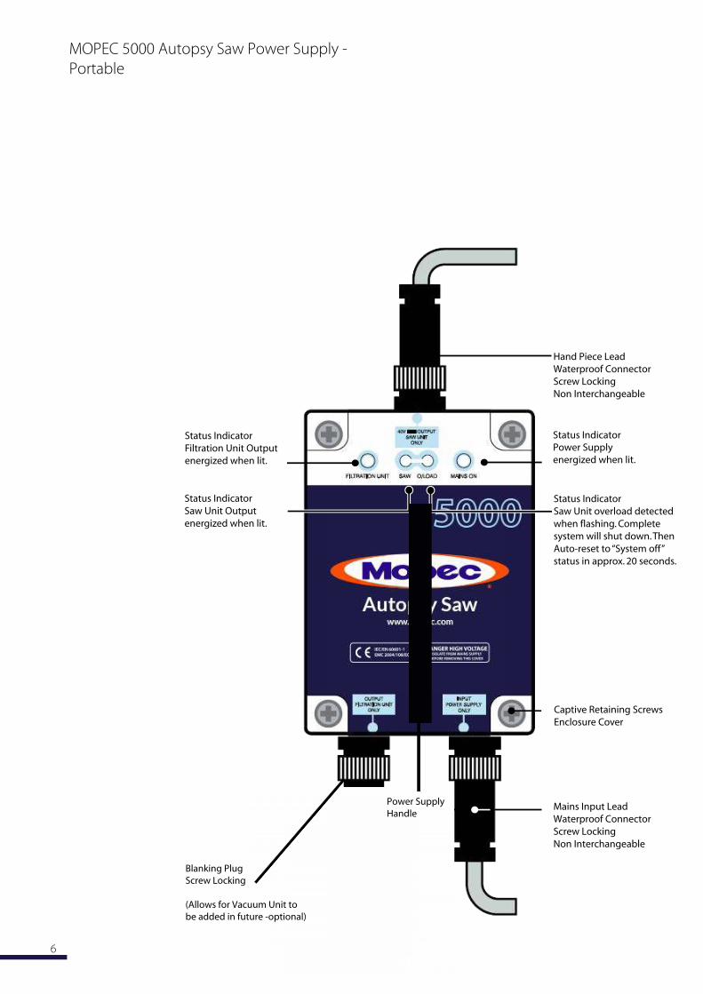
Status Indicator
Filtration Unit Output
energized when lit.
Captive Retaining Screws
Enclosure Cover
Status Indicator
Saw Unit Output
energized when lit.
Status Indicator
Saw Unit overload detected
when flashing. Complete
system will shut down. Then
Auto-reset to “System off”
status in approx. 20 seconds.
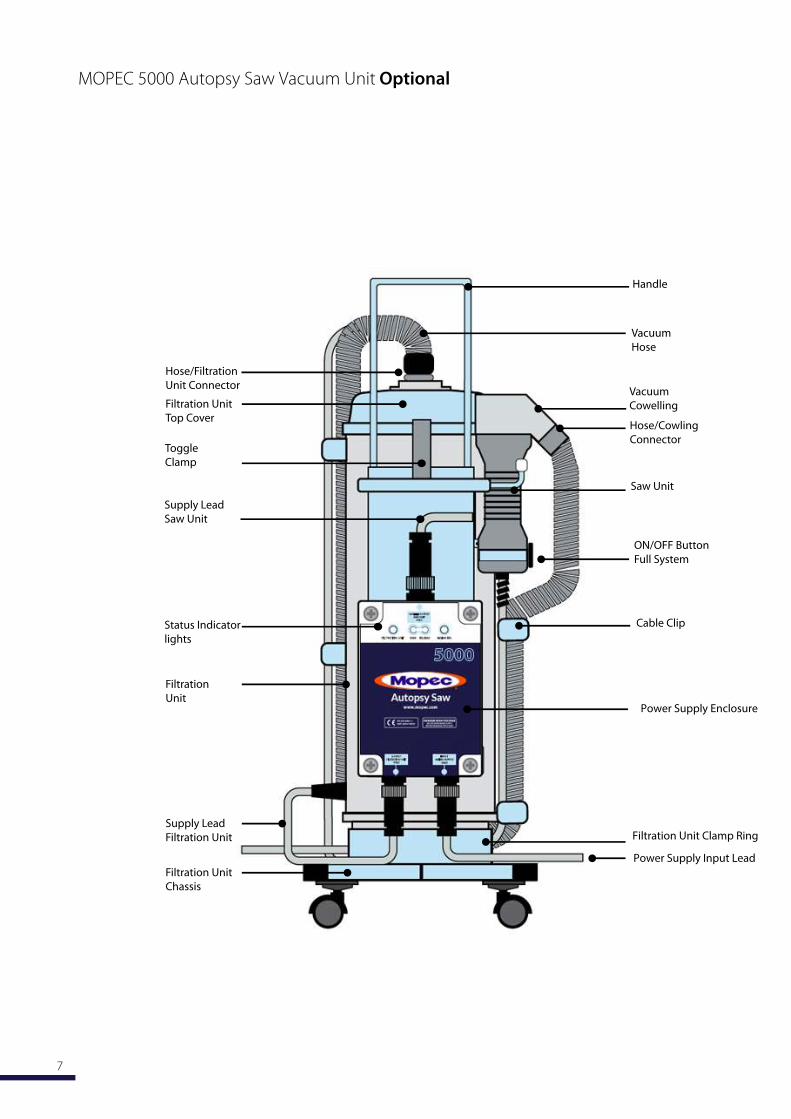
Saw Unit
ON/OFF Button
Full System
Supply Lead
Saw Unit
Vacuum
Hose
Hose/Filtration
Unit Connector
Filtration Unit
Top CoverHose/Cowling
ConnectorToggle
Clamp
Vacuum
Cowelling
Filtration
Unit
Filtration Unit
Chassis
Supply Lead
Filtration Unit
Handle
Cable Clip
Powe
Status Indicator
lights
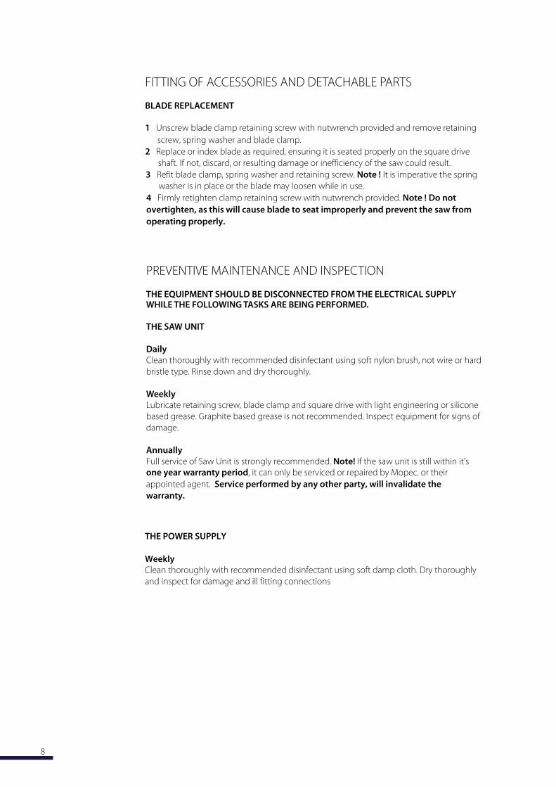
FITTING OF ACCESSORIES AND DETACHABLE PARTS
BLADE REPLACEMENT
Unscrew blade clamp retaining screw with nutwrench provided and remove retaining
screw, spring washer and blade clamp.
Replace or index blade as required, ensuring it is seated properly on the square drive
shaft. If not, discard, or resulting damage or inefficiency of the saw could result.
Refit blade clamp, spring washer and retaining screw. Note ! It is imperative the spring
washer is in place or the blade may loosen whil in use.
PREVENTIVE MAINTENANCE AND INSPECTION
THE EQUIPMENT SHOULD BE DISCONNECTED FROM THE ELECTRICAL SUPPLYWHILE THE FOLLOWING TASKS ARE BEING PERFORMED.
THE SAW UNIT
DailyClean thoroughly with recommended disinfectant using soft nylon brush, not wire or hard
bristle type. Rinse down and dry thoroughly.
WeeklyLubricate retaining screw, blade clamp and square drive with light engineering or silicone
based grease. Graphite based grease is not recommended. Inspect equipment for signs of
damage.
Annually
Full service of Saw Unit is strongly recommended. Note!
it can only be serviced or repaired by . or their
appointed agent. will invalidate th
warranty.
THE POWER SUPPLY
WeeklyClean thoroughly with recommended disinfectant using soft damp cloth. Dry thoroughly
and inspect for damage and ill fitting connections
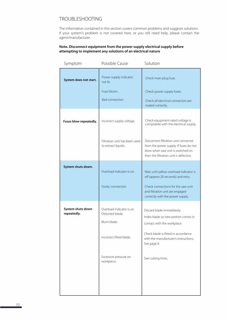
TROUBLESHOOTING
The information contained in this section covers common problems and suggests solutions.
If your system’s problem is not covered here, or you still need help, please contact the
agent/manufacturer.
Note. Disconnect equipment from the electrical supply before
attempting to implement any solutions of an electrical nature
Possible Cause
System does not start.Check main plug fuse.
Check power supply fuses.
Check all electrical connectors are
mated correctly.
Bad connection.
SolutionSymptom
supply indicator
not lit.
Fuse blown.
Fuses blow repeatedly. Incorrect supply voltage.
Disconnect filtration unit connector
from the power supply. If fuses do not
blow when saw unit is switched on
then the filtration unit is defective.
Filtration unit has been used
to extract liquids.
System shuts down
repeatedly.
Overload indicator is on.
Distorted blade.
Blunt blade.
Incorrect fitted blade.
Discard immediately.
Index blade so new portion comes in
contact with the workplace.
Check blade is fitted in accordance
with the manufacturer’s instructions.
See page 8.
See cutting hints
System shuts down.
Overload indicator is on. Wait until yellow overload indicator is
off (approx 20 seconds) and retry.
Check connections for the saw unit
and filtration unit are engaged
correctly with the power supply.
Faulty connection.
Excessive pressure on
workpiece.
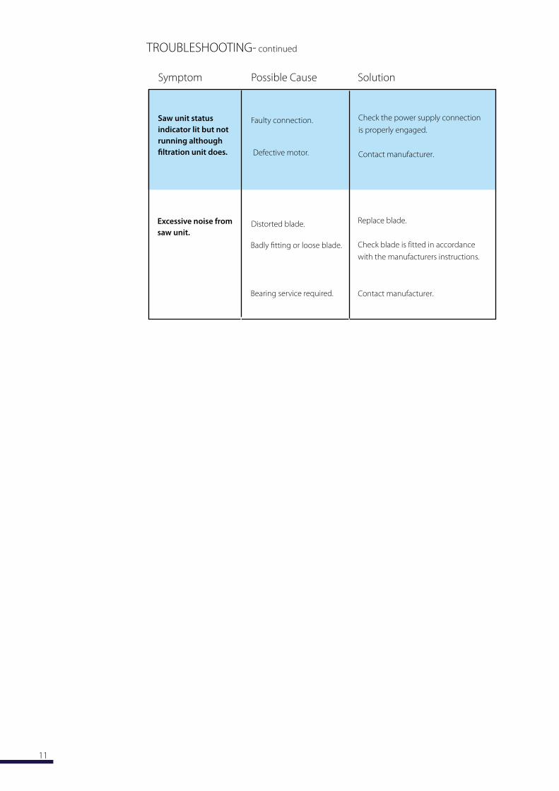
TROUBLESHOOTING- continued
Possible Cause
Saw unit status
indicator lit but not
running although
filtration unit does.
Check the power supply connection
is properly engaged.
Contact manufacturer.Defective motor.
SolutionSymptom
Faulty connection.
Excessive noise from
saw unit.Distorted blade.
Badly fitting or loose blade.
R blade.
Check blade is fitted in accordance
with the manufacturers instructions.
Contact manufacturer.Bearing service required.

ISOLATE FROM ELECTRICAL SUPPLY BEFORE REMOVING COVER
The third fuse is an anti surge fuse. Fuse type and ratings are marked adjacent
to the fuse holders or alternatively see page 14.
Undo the four captive retaining screws to remove the cover.
Prior to replacement ensure that the rubber seal
set into the underside cover has not
been disturbed.
FUSE REPLACEMENT
Retighten cover fully ensuring that
the cover is seated properly.
Status Indicator
Filtration Unit Output
energized when lit.
Captive Retaining Screws
Enclosure Cover
Status Indicator
Saw Unit Output
energized when lit.
Status Indicator
Saw Unit overload detected
when flashing. Complete
system will shut down. Then
Auto-reset to “System off”
status in approx. 20 seconds.
Waterproof Electrical
Connectors
Screw Locking-Non
Interchangeable
Waterproof Electrical
Connector
Screw Locking-Non
Interchangeable
CUTTING HINTS
The M 5000 oscillating saw has been designed and constructed to provide effortless
and highly efficient cutting in its appropriate areas of usage. We suggest a trial cutting
period applying the least pressure possible to the workpiece until fully accustomed with
the efficiency. Excessive pressure is not required as this will reduce the speed of cut.
If you experience difficulty then consult the Troubleshooting Causes and Solutions on pages
10 and 11.
Suitable safety protection must be worn at all times during cutting.
DISINFECTION AND STERILIZATION
The saw unit only is capable of withstanding temperatures between - degrees to
+ degrees . This must be born in mind when considering a disinfection or
sterilization method.
Autoclaving of this equipment is not recommended.
Only use cleaning agents that are safe for use on metals. We do not recommend the use
of Hy or corrosive cleaners as possible corrosion could result.
We advise gentle scrubbing with a soft non metallic brush, rinsing with clean water and
drying where necessary. Do not direct high pressure water jets at any part of the equipment,
this could invalidate the warranty.
All cleaning agents should be mixed, stored and applied according to the manufacturers
instructions.
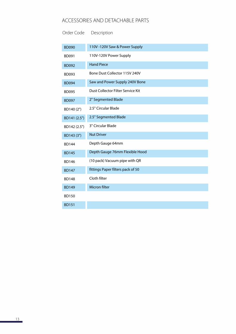
ACCESSORIES AND DETACHABLE PARTS
Order Code Description
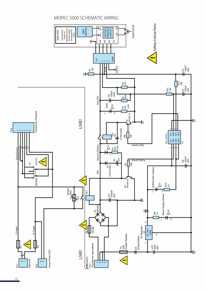
5000 SCHEMATIC WIRING
STA
RT/
STO
P
MO
TOR
PR
INTE
DC
IRC
UIT
SA
WM
OTO
R
SA
W U
NIT
Con
nect
ions
show
n at
op
pos
ite e
nd o
fp
ower
sup
ply
encl
osur
e fo
rcl
arity
A6
A5
A4
A3
I/O
I/O
M +
M -
SA
W
PL
5
1 2 3 4 5
EA
RTH
1 2 3 4 5 6
LIV
E!
LIV
E!
L F
use
d
N F
use
d
L N
Ma
ins I
N
Pu
mp
Po
we
r O
UT
PL
1
PL
2
2 1 2 1
F2
F1
Va
risto
r
25
0V
22
0/2
30
S1
11
0/1
15
-V VR
1
RL
1F
3
PL
4
Tra
nsfo
rme
r se
co
nd
arie
s
EA
RT
H
1 2 3 4
5A
QB
D1
KB
U4
D
Fu
sib
le R
esis
tor
D4
S1
PB
-E3
/84
A
F4
22
R
IN
OU
T
GN
D
Pump Control
Saw Control
5V
Re
gu
lato
r
U1
Ma
ins S
up
ply
(G
ree
n)
+C
1
47
00
uF
63
V
40
VV
acu
um
(G
ree
n)
+C
3
22
uF
35
V
0V
13
2
5V
0V
2
2
C5
10
0u
F
25
V
C4
10
0u
F
25
V
0V
Sa
w 4
0V
0V
C6
10
0u
F
25
V
1
1
OV
ER
LO
AD
(Y
ello
w)
R11
10
k
C2
10
0u
F
10
0V
R1
2
10
k
R1
10
k
R4
3k9
R5
100R
R6
0R
1
R1
0
1k
R9
1k
0.5
W
5V
21
SA
W
PL
3
Tra
nsfo
rme
r P
rim
arie
s
Th
erm
al F
use
Ou
tP
1*
P1
Th
erm
al F
use
In P2
*
P2
R8
10
k
On/O
ff
Q3
BC
X56-1
6
RL2
D8
S1P
B-E
3/8
4A
R4
3k9
0.5
W
D5
m m
D2
m m
2
10
k
R7
S1P
B-E
3/8
4A
D7
m m
D3
D9
20V
Q2
BC
X56-1
6
D6
m m1 2 3 4
8
PIC
1 2
F6
75
Vcc
GP
5
GP
4
GP
3
Vss
AN
0
GP
1
GP
2
IC1
6 57
!
!
!!
!
!S
afe
ty C
riti
cal P
art
s
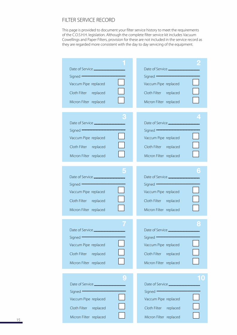
FILTER SERVICE RECORD
This page is provided to document your filter service history to meet the requirements
of the C.O.S.H.H. legislation. Although the complete filter service kit includes Vacuum
Cowellings and Paper Filters, provision for these are not included in the service record as
they are regarded more consistent with the day to day servicing of the equipment.
Date of Service
Signed
Vaccum Pipe replaced
Cloth Filter replaced
Micron Filter replaced
1Date of Service
Signed
Vaccum Pipe replaced
Cloth Filter replaced
Micron Filter replaced
2
Date of Service
Signed
Vaccum Pipe replaced
Cloth Filter replaced
Micron Filter replaced
3Date of Service
Signed
Vaccum Pipe replaced
Cloth Filter replaced
Micron Filter replaced
4
Date of Service
Signed
Vaccum Pipe replaced
Cloth Filter replaced
Micron Filter replaced
5Date of Service
Signed
Vaccum Pipe replaced
Cloth Filter replaced
Micron Filter replaced
6
Date of Service
Signed
Vaccum Pipe replaced
Cloth Filter replaced
Micron Filter replaced
7Date of Service
Signed
Vaccum Pipe replaced
Cloth Filter replaced
Micron Filter replaced
8
Date of Service
Signed
Vaccum Pipe replaced
Cloth Filter replaced
Micron Filter replaced
9Date of Service
Signed
Vaccum Pipe replaced
Cloth Filter replaced
Micron Filter replaced
10
CONDITIONS OF WARRANTY
Should the equipment covered by this warranty become inoperative because of defective
material(s) or workmanship, undertake at their own discretion to repair or
replace it at no charge to the purchaser, subject to the following conditions :-
1 That the equipment has been used with care and shows no sign of abuse, neglect or
accidental damage.
2 That the equipment has only been used for the purpose(s) for which it was designed.
3 That the preventive maintenance has been performed in accordance with the
manufacturer’s instructions.
4 That no attempt to repair or dismantle any part of the equipment has been made, except
by a M representative or an appointed agent of M .
5 That any claim for repair or replacement be made within one calendar month of the problem arising.
6 The conditions of this warranty remain in force for a period of twelve months from the
date of purchase.
7 This warranty does not affect your statutory rights.
The policy of M is one of continuous product development, and ensuring our
customers the best possible service. To achieve this, specifications and details may be
subject to change without prior notice.
Equipment owners outside the United should consult the distributor/agent from
whom they purchased the equipment regarding spare parts and repair facilities.
The distributor/agent will advise on the best course of action to take.
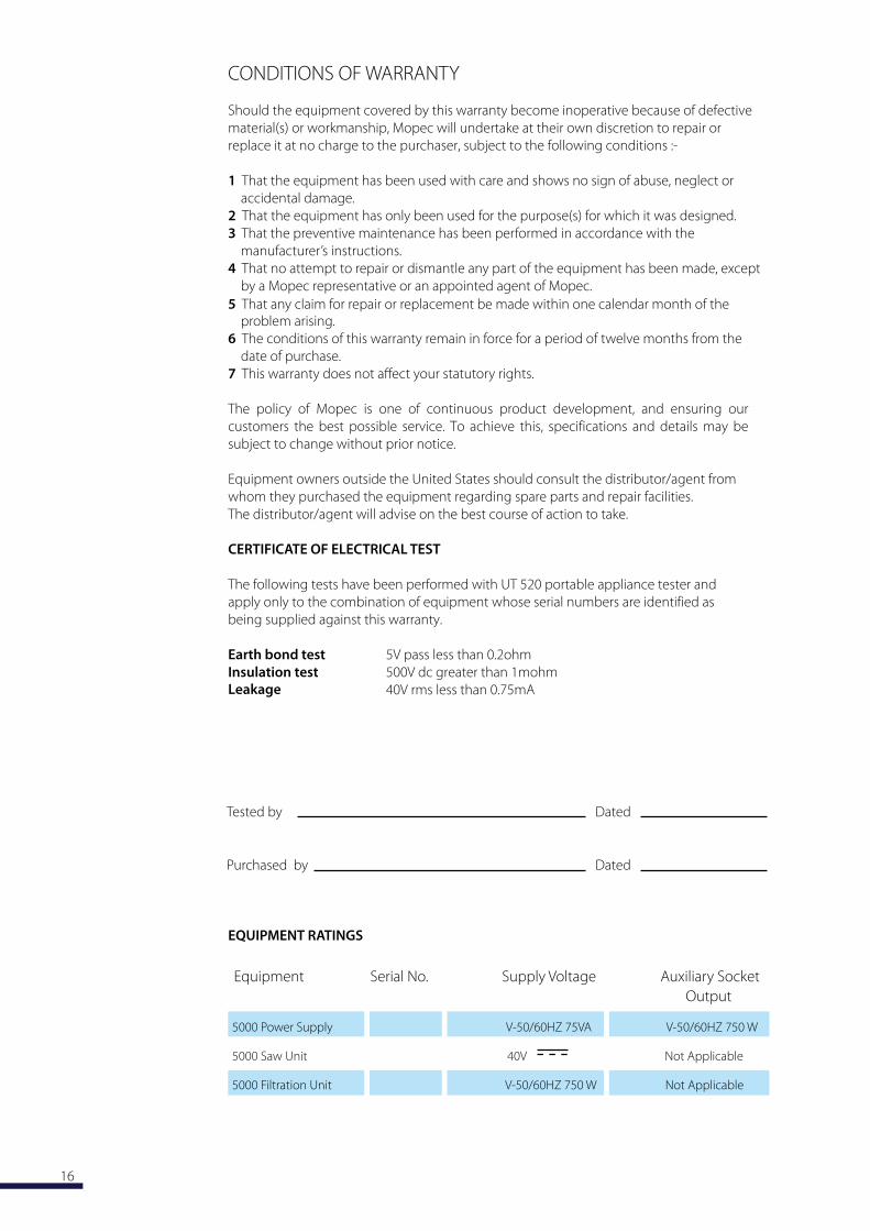
CERTIFICATE OF ELECTRICAL TEST
The following tests have been performed with portable appliance tester and
apply only to the combination of equipment whose serial numbers are identified as
being supplied against this warranty.
Earth bond test
Insulation test
EQUIPMENT RATINGS
Equipment Serial No. Supply Voltage Auxiliary Socket
Output
5000 Power Supply V-50/60HZ 75VA V-50/60HZ 750 W
5000 Saw Unit 40V Not Applicable
5000 Filtration Unit V-50/60HZ 750 W Not Applicable
Tested by Dated
Purchased by Dated
21750 Coolidge Hwy.Oak Park, Michigan 48237 USA
T +1 248-291-2040F +1 248-291-2050E [email protected] W www.mopec.com
2002/289
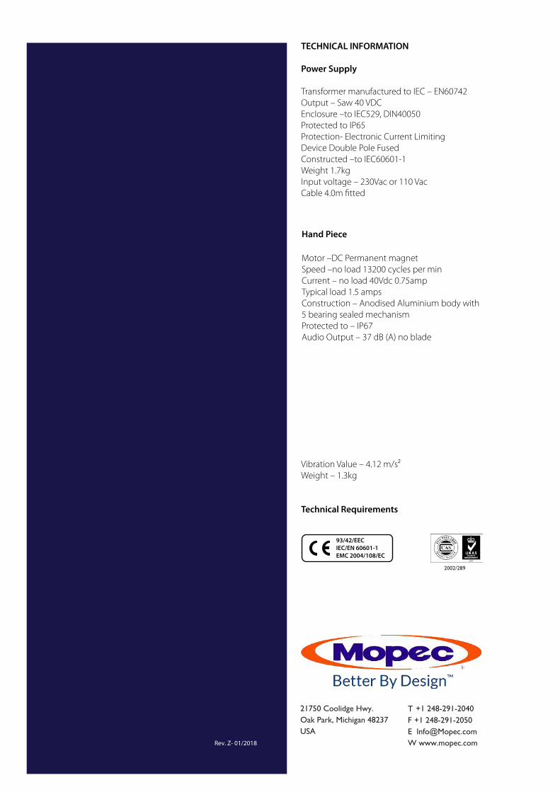
TECHNICAL INFORMATION
Power Supply
Transformer manufactured to IEC – EN60742
Output – Saw 40 VDC
Enclosure –to IEC529, DIN40050
Protected to IP65
Protection- Electronic Current Limiting
Device Double Pole Fused
Constructed –to IEC60601-1
Weight 1.7kg
Input voltage – 230Vac or 110 Vac
Cable 4.0m fitted
Hand Piece
Motor –DC Permanent magnet
Speed –no load 13200 cycles per min
Current – no load 40Vdc 0.75amp
Typical load 1.5 amps
Construction – Anodised Aluminium body with
5 bearing sealed mechanism
Protected to – IP67
Audio Output – 37 dB (A) no blade
Vibration Value – 4.12 m/s2
Weight – 1.3kg
Technical Requirements
93/42/EEC
IEC/EN 60601-1
EMC 2004/108/EC