Embed Size (px)
Citation preview

Scalable Computing: Practice and Experience
Volume 18, Number 4, pp. 361–373. http://www.scpe.org
DOI 10.12694/scpe.v18i4.1334ISSN 1895-1767c⃝ 2017 SCPE
MOORECUBE: A SCALABLE AND FLEXIBLE ARCHITECTURE
FOR CLOUD COMPUTING DATA CENTERS ON MULTI-PORT SERVERS
AREZOO JAHANI AND LEYLI MOHAMMAD KHANLI ∗
Abstract. Networks provide the infrastructure of cloud computing data centers. Servers in data centers grow to respond tothe growing user demands. Data center scalability and flexibility in the use of multi-port servers is a challenging issue. Heretofore,no method has been considered for scalability and flexibility issues. This paper proposes a new architecture called MooreCubethat can increase network scalability and decrease network diameter as well as increase flexibility. MooreCube is a scalable andflexible architecture that each multi-port server directly connected to other servers via bi-directional links, without using any switch.Furthermore, MooreCube is a recursively defined architecture that uses Moore graph as Building Block (BB) structure and usesthe hierarchical structure to meet high scalability. The paper proposes a multipath routing to increase fault tolerance and decreaselinks burden. MooreCube architecture compared with other switchless architectures that use reserved ports to increase scalability.The simulation results show MooreCube increase scalability and flexibility along with decrease the diameter of the network.
Key words: Data center network, Cloud computing, Network architecture, Multi-port servers, Scalability, Multipath routing.
AMS subject classifications. 68M14, 68M10
1. Introduction. Cloud computing uses data center networking (DCN) as an infrastructure to provideservices [1]. The powers of data centers should be enhanced with an increase in the service request andcomputational, storage and processing requirements [2, 3]. Therefore the architecture of data centers mustbe scalable and loosely as possible to add and/or subtract server/s to data centers [4, 5]. In addition, toexposure better service, the architecture of data centers should provide communication between servers that ispossible by high-speed links, bilateral and optimized routing [6].
Adding new server/s to data center has some Issues. The first issue is the network flexibility that possibleadding any new server to the data center. The former architectures have limitations in adding new servers.Because most of them use the reserved port and when the reserved ports completed, adding any new server isnot possible [3, 7]. Cost is the second issue. Adding new server/s has cost like the price of adding the new link,switch, and router. Although it has some other issues like inefficient network development which limit the useof all server capacity because of inefficient development [8, 9]. Therefore considering these issues will help indesigning new data center architecture. Design goals of the data center are; scalability, fault tolerance, latency,network capacity, simplicity, flexibility, and network configuration that will describe in detail [2, 32].
• Scalability: Ease of adding new server/s to data center networks. Scalability shows that adding anynew server should not modify the DCN architecture (topology).
• Fault tolerance: The DCN should be accessible in presence of fault. Mostly, the lack of alternativeroutes and servers lead to irreparable damage.
• Latency: Delay in sending and receiving the message has a direct relation with network diameter(number of steps between source and destination). So latency in DCN architecture is important. Thenetwork diameter is most important factor in architecture and should not increase with enhancingnetwork scalability.
• Network capacity: Total network capacities such as server’s CPU, hard and link bandwidth should beaccessible and using all network capacity should be possible.
• Simplicity: Ease of creating architecture is an important issue that must be considered. Use of formerrouting would be possible if the DCN architecture not modified in adding any new server/s.
• Flexibility: Flexibility can be defined in two ways. Network Flexibility and flexibility in using multi-port servers. Network Flexibility means the possibility of using small and very large architecture scalein presence of all network features. Flexibility in using multi-port servers as the name implies is possibleusing servers with a different number of ports.
∗Faculty of Electrical and Computer Engineering, University of Tabriz, Tabriz, Iran. ([email protected], l-khanli@
tabrizu.ac.ir)
361

362 A. Jahani, L. M. Khanli
• Modularity: Recursive architecture has modularity concept. This kind of architectures, use a basicstructure that repeated with adding any new server and known as modularity architectures.
Data center architectures include in three general categories: switch-centeric architecture, server-centericarchitecture and switchless architecture [2, 6, 7]. First two categories have the switch in their architecture toconnect servers. The only difference between them is the location of network routing. In a switch-centericarchitecture, the switch is responsible for message routing in the network. But in server-centric architecture,servers set up network routing. The last one not uses the switch in DC architecture and connects servers directlyusing multi-port servers [2]. Using any switch in DC architecture has some advantages like; reducing the costand increasing the network efficiency.
This paper proposes MooreCube as a new architecture that not use any switch to connect servers. Thisnew architecture uses multi-port servers to connect servers directly with bi-directional links. MooreCube useMoore graph as a basic Building Block (BB) and hierarchical structure to increase network scalability. Mooregraph is a regular graph that is known with degree and diameter [12, 13]. The paper uses multipath routing toincrease fault tolerance and reduce the burden of links [14, 15].
The reminder of paper is organized as follow; section 2, studies previous solutions. Section 3 describesMooreCube architecture. Section 4, shows multipath routing and in continue, section 5 evaluates the MooreCubestrategy and at last, section 6 express conclusion and future works.
2. Related works. Researchers are trying to find a way to properly connect servers to each other toreduce the network diameter and increase network scalability. Many researchers have been done activities inthis area. In general, the DCN architectures divided into three categories include; switch-centric architecture,server-centric architecture, and switchless architecture. In switch-centric architectures, the switch is responsiblefor routing and this architecture mostly uses optical interconnections to send and receive messages [7, 11].The first switch-centric architecture was proposed in 2008 called FatTree [16]. FatTree uses some switchesand servers as Building block and increases the number of switches with adding any new server/s. FatTreehas the three-level architecture that the servers are at the lowest level and switches are in two high levels ofarchitecture. Depending on the number of servers that are at the lowest level, switches have the port. Theselayers are connected to each other in form of tree. However, each routing between servers in lowest level needsto use existing switches in the high level. In the worst case, all the pairs of servers are linked together. So,using the switches in this way, make switches as a bottleneck. Portland architecture [17], is another architecturethat uses FatTree with a new send/receive protocol [18]. VL2 is another architecture that focuses on the useof server capacity and facilitates the routing with using of flat addresses. SWDC [23], Poincare [22], Scafida[21], S2 [20], Jellyfish [19] and RingCube [7] are also switch-centric architectures. All of the solutions use switchbeside server in DCN architecture.
Server centric architecture also has a switch but use the servers as a router. DCell [24], BCube [25],Ficonn [26], FlatNet [27], HCN & BCN [28], Dpillar [29], SWCube [30], FleCube [31, 32], DCube [33], Fsquare[34] and sprintNet [35] are server-centric architecture. Using the switch in this kind of architecture may lead tobottleneck and increase cost and scalability of the network. The third category of DCN is switchless architecturewhose does not use any switch to connect servers. But servers are directly connected to one another by thebidirectional link. Do not use the switch in DC architecture reduce the cost and increase the network efficiency[35]. Because in the absence of switch, the cost, and power that are needed to switch cares, are stored. Also ifwe do not have the switch, switches will not have downtime and network fault tolerance will be greater. Delayin the switch is also another reason for not using the switch. Because each switch has few microsecond delay tosend and receive data. We can use the server instead of switch in DCN and increase network scalability [33].
CamCube [36], Smallworld [23], NovaCube [37] and FleCube [2] are switchless architecture. CamCube usesthree-dimensional Torus structure for connectivity between the servers. This architecture needs 6-port serversin all circumstances. The Torus-3D indicated with k-array-3-Cube that the number of servers (S) computedwith Eq. (2.1) and Diameter (D) computed with Eq. (2.2).
S = kn = k3 (2.1)
D = 3
√
(kn) = 3
√
(k3) = k (2.2)
MooreCube: A Scalable and Flexible Architecture for Cloud Computing Data Centers on Multi-port Servers 363
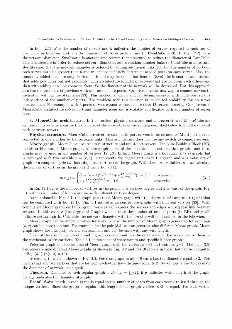
In Eq. (2.1), S is the number of servers and k indicates the number of servers required in each row ofCamCube architecture and n is the dimension of Torus architecture (in CamCube n=3). In Eq. (2.2), D isthe network diameter. Smallworld is another architecture that presented to reduce the diameter of CamCube.This architecture in order to reduce network diameter, add a random number links to CamCube architecture.Results show that the network diameter is reduced by adding additional links [23], but the number of ports oneach server must be greater than 6 and we cannot definitely determine needed ports on each server. Also, therandomly added links are only shortest path and may become a bottleneck. NoveCube is another architecturethat adds new links but not randomly. This architecture found pair servers that are far from each others andthen with adding new link connects them. So the diameter of the network will be decreased. But this approachalso has the problems of previous work and needs more ports. SprintNet has the new way to connect servers toeach other without use of switches [33]. This method is flexible and can be implemented with multi-port serversindependent of the number of ports. The problem with this solution is its limited scalability due to serverport number. For example, with 3-ports servers cannot connect more than 42 servers directly. Our presentedMooreCube architecture solves port and diameter issue and is scalable and flexible with any number of serverports.
3. MooreCube architecture. In this section, physical structure and characteristics of MooreCube areexpressed. In order to measure the diameter of the network, one-way routing described below to find the shortestpath between servers.
Physical structure. MooreCube architecture uses multi-port servers in its structure. Multi-port serversconnected to one another by bidirectional links. This architecture does not use any switch to connect servers.
Moore graph. MooreCube uses recursive structure and multi-port servers. The basic Building Block (BB)in this architecture is Moore graph. Moore graph is one of the most famous mathematical graphs, and thesegraphs may be used in any number of vertices [12, 13]. In fact, Moore graph is a k-regular (k > 2) graph thatis displayed with two variable n = (v, g). v represents the degree vertices in the graph and g is waist size ofgraph or a complete cycle (without duplicate vertices) of the graph. With these two variables, we can calculatethe number of vertices in the graph (n) using Eq. (3.1).
n(v, g) =
{
(1 + (v − 1)((g/2)−1) + v∑(g−4)/2
r=0 (v − 1)r, if g is even
1 + V∑(g−3)/2
r=0 (v − 1)r, otherwise(3.1)
In Eq. (3.1), n is the number of vertices in the graph. v is vertices degree and g is waist of the graph. Fig.3.1 outlines a number of Moore graphs with different vertices degree.
As mentioned in Fig. 3.1, the graph (n=4) is a Moore graph with the degree (v=3) and waist (g=3) thatcan be computed with Eq. (3.1). Fig. 3.1 indicates various Moore graphs with different vertices [38]. Withcompliance Moore graph on DCN, graph vertices will express the servers and edges will express link betweenservers. In this case, v (the degree of Graph) will indicate the number of needed ports (in BB) and g willindicate network girth. Calculate the network diameter with the use of g will be described in the following.
Moore graph can be different values for v and g. also the number of Moore graphs generated for each pair(v, g) can be more than one. For example, for the pair (3,5) we can generate nine different Moore graph. Mooregraph shows the flexibility for any environment and can be used with any wire length.
Some of the specific values of v and g graphs created and has the certain name that was given to them bythe mathematical researchers. Table 3.1 shows some of these names and specific Moore graphs.
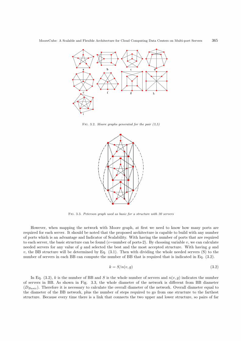
Peterson graph is a special case of Moore graph with the vertex as v=3 and waist as g=5. The pair (3,5)can generate nine different Moore graphs as shown in Fig. 3.2 and has 10 servers in total that can be computedin Eq. (3.1) (n(v, g) = 10).
According to what is shown in Fig. 3.2, Peterson graph in all of 9 cases has the diameter equal to 2. Thismeans that any two vertices that are far from each other have distance equal to 2. So we need a way to calculatethe diameter of network using girth.
Theorem. Diameter of each regular graph is DBasic = ⌊g/2⌋, if g indicates waist length of the graph.(DBasic indicates the diameter of graph.)
Proof: Waist length in each graph is equal to the number of edges from each vertex to itself through theunique vertices. Since the graph is regular, this length for all graph vertices will be equal. For each vertex,

364 A. Jahani, L. M. Khanli
Fig. 3.1. Moore graphs with different number of vertices
Table 3.1
Specific Moore graph
(v,g) Name of Moore Graph
(3,5) graph Petersen
(3,6) graph Heawood
(3,8) graph Levi
(4,6) graph Wong
(5,6) graph order-4 generalized triangle
(7,5) graph Hoffman-Singleton
a path that shows the number of edges from the vertex to itself has passed the farthest vertex of the graphand returns to the source vertex. So the waist graphs show a complete cycle through the farthest vertex ofthe graph. Obviously, the length of the waist can be halved to calculate the farthest vertex. As mentioned inFig. 3.2(a), the distance from each vertex to farthest vertex in the graph is 2. So for different values of g, thenetwork diameter is equal to low g/2 and prove that DBasic = ⌊g/2⌋.
Opposite Theorem. For every regular graph with DBasic diameter, waist length g calculated as 2DBasic
or 2DBasic + 1.
Peterson graph has vertex degree equal 3. This means if basic BB structure degree was 3, we need tothree ports of multi-port servers. For network scalability, we can connect BB structures with links and in ahierarchical structure. Suppose the first case of Peterson graph is used as the basic structure of architecture.This basic structure has 10 servers that can be put k number of these structures over each other as showed inFig. 3.3. For example, if we want to have 30 servers, we should 3 BB over each other.
As mentioned in Fig. 3.3, to scale the network, two extra port of each server is required to connect BBstructures on top and bottom to each others. The proof shows that the number of ports per server in MooreCubeis v + 2. v ports to connect to other servers in same BB and 2 port to connect to other BB on top or bottomof that.
MooreCube: A Scalable and Flexible Architecture for Cloud Computing Data Centers on Multi-port Servers 365
Fig. 3.2. Moore graphs generated for the pair (3,5)
Fig. 3.3. Peterson graph used as basic for a structure with 30 servers
However, when mapping the network with Moore graph, at first we need to know how many ports arerequired for each server. It should be noted that the proposed architecture is capable to build with any numberof ports which is an advantage and Indicator of Scalability. With having the number of ports that are requiredto each server, the basic structure can be found (v=number of ports-2). By choosing variable v, we can calculateneeded servers for any value of g and selected the best and the most accepted structure. With having g andv, the BB structure will be determined by Eq. (3.1). Then with dividing the whole needed servers (S) to thenumber of servers in each BB can compute the number of BB that is required that is indicated in Eq. (3.2).
k = S/n(v, g) (3.2)
In Eq. (3.2), k is the number of BB and S is the whole number of servers and n(v, g) indicates the numberof servers in BB. As shown in Fig. 3.3, the whole diameter of the network is different from BB diameter(DBasic). Therefore it is necessary to calculate the overall diameter of the network. Overall diameter equal tothe diameter of the BB network, plus the number of steps required to go from one structure to the fartheststructure. Because every time there is a link that connects the two upper and lower structure, so pairs of far

366 A. Jahani, L. M. Khanli
Table 3.2
Calculate best waist length with degree=3
v g n(v, g) S/n(v, g) = k S DBasic =
⌊g/2⌋
DTotal =
DBasic +
⌊k/2⌋
3 1 1 30 30 1/2 16
3 2 2 15 30 1 8
3 3 4 7.5 30 1 4
3 4 6 5 30 2 4
3 5 10 3 30 2 3
3 6 14 2.14 30 3 4
structures has a length of ⌊k/2⌋. The overall diameter of the network is calculated by Eq. (3.3).
DTotal = DBasic + ⌊k/2⌋ (3.3)
In Eq. (3.3), Dtotal is the overall diameter of the network, though DBasic is BB diameter and k is thenumber of BB.
Practical example. Suppose we have 30 servers and each server has 5 ports. In order to find the numberof required BB, first, we should compute the degree of the basic graph. Because the servers have five ports,two ports of them will be reserved to connect BBs together. Then we have three ports for BB graph and v=3.For v=3, we can consider different waist lengths. Table 3.2 shows the number of servers used in any structurewith different g. in this table, DTotal can be calculated for each g. so the most appropriate structure will beselected. It is obvious the row with lowest DTotal in the table is the best structure. But no need to calculateall values for all of g. because g and DTotal has a regular trend. DTotal will be reduced with increasing g andthen enhanced when passed the best value of g. this regular trend helps us to choose the most suitable amountof g. in Table 3.2, the lowest of DTotal belong to the fifth row. So the value of g = 5 will be chosen that has 10servers in the structure of the BB.
According to Table 3.2, DTotal with different g, will be declined at first and then with passing the bestvalue of g, start to enhanced. So choose the most optimal value for the variable g easily computed with thecomparison of values in the DTotal column.
4. Routing. MooreCube structure constructed of many BB and each BB constructed of many servers.Routing in each BB can be done by broadcast shortest path (BSP) algorithm. It is essential to note thatrouting algorithms run once before DCN running. So DCN uses the results of routing algorithm. In fact, allroutes should be saved in routing tables for future use. So the complexity of routing algorithm will not haveany effect on the routing between data centers and most of the routing algorithm can be easily used for routing.Finding the shortest path with BSP is very simple algorithm where each server in order to find the shortestroute to the destination server, first sends a message includes destination server name to all neighbors. Theneighbors who received this message sends the message to their neighbors. This process continues and if themessage received by destination server, process terminated and messages come back to the source server andcollect the intermediate servers as a route from source to destination. The source has received several messagesfrom different directions to pass each of which have the shortest path as the best path is selected. Routing ineach pair of BB is carried out by a link between them. Each server who wants send a message to a server inanother BB, there are two choices:
• Use the link that connects the source to destinations neighbor (in destination BB).• Use the link that connects destination to sources neighbor (in source BB).
Routing procedure between each source and the destination indicated in the algorithm 1.As indicated in the algorithm 1, this algorithm first check if source and destination are the neighbor. If
they were the neighbor, the link between them returned as route (rows 1-3). Otherwise, select one of the linksbetween two BB as the intermediate link in order to find the shortest path (row 4). Then depending on whichlink is chosen, calculate the shortest path using BSP algorithm (rows 5-9).
MooreCube: A Scalable and Flexible Architecture for Cloud Computing Data Centers on Multi-port Servers 367
Algorithm 1 BSP(src,dst)
Require: src: source server;dst: destination server;src and dst located in BB;
1: if src and dst are adjacent then2: return (src , dst);3: end if
4: obtain ( link(src , s1) between BB src and dst — link(s2 , dst) between BB src and dst);5: if link(src , s1) then6: return (BSP(src , s1) , dst);7: else
8: return (src , BSP(s2 , dst));9: end if
MooreCube features.
• Scalability: MooreCube scalability enhances by increasing the number of ports (server ports) as wellas network diameter. According to Eq. (3.2), the number of required BB is equal to k = S/n(v, g).So the number of servers depends on k and the number of ports in BBs servers. As a result, the totalnumber of servers in each layer of the hierarchical structure will be calculated by Eq. (4.1).
Sk = k × n(v, g) (4.1)
Eq. (4.1) indicates the number of possible servers in each layer of hierarchical structure k. S k is thenumber of servers for all k layer. K is the number of required BB and n(v, g) indicates number ofservers in each BB. Increase the number of servers with increasing variable k in Section 5 and will beshown in experiments related to scalability.
• Flexibility: Flexibility is one of the most important features in MooreCube architecture. The purposeof the flexibility is using architectural with the different number of ports. MooreCube is capable ofusing multi-port servers in architecture. Although the architecture FleCube [2] also was dealt with thisissue in 2015. But FleCube focused on only flexibility and scalability was not adhered to. For example,when using FleCube architecture and 3-port servers we cannot have more than 42 server connectionand adding more servers is not possible in this architecture. Therefore, the proposed solution unlikeprevious methods focusing on both flexibility and scalability.
• Network diameter: Network diameter indicates the number of steps from a source server to farthestserver on the network. According to section (3.1.1) and proved theorem we know that the networkdiameter can be determined by variable g and the overall diameter of the network is DTotal = DBasic+⌊m/2⌋.
• Bidirectional bandwidth: Network bandwidth indicates data transfer rate on network connections.The criterion is the most important criteria for determining the speed of a network. Accordingly,bi-directional bandwidth indicates data transmission rate by network connections. MooreCube archi-tecture has the bidirectional bandwidth. Eq. (4.2) shows the bidirectional bandwidth of MooreCubearchitecture.
v + 2 ≤ bidirectional − bandwidth ≤ n(v, g) (4.2)
In Eq. (4.2), v is the number of ports in each BB.• Theorem: Bidirectional bandwidth in MooreCube structure is accordance with Eq. (4.2).Proof: To calculate the bidirectional bandwidth, the network should be divided into two equal part.The simplest way to divide MooreCube is to divide it into two separate BB that have equal servers. Inthis case, the link between these two parts will be equal to the number of servers in each BB unit. allservers of two connected BB have a link together. So at best case, bidirectional bandwidth is equal to

368 A. Jahani, L. M. Khanli
the number of servers in BB. In the worst case, there is only a BB should be divided into two equalparts. In dividing time, if the number of servers is even, we can divide them simply in two parts andit is clear that only v + 2 link between these two parts can connect parts to each others. Otherwise,if the number of servers is odd, we can omit one of them and use the earlier case to calculate networkdiameter.
• Links and cost: Given that more links in any architecture, increase fault tolerance on the network.But connecting any two servers is not possible. Because it led to wiring problems and eliminate theflexibility and scalability of the network. So we should make a trade-off between the number of links andscalability, flexibility and wiring problems. The number of links should be low as much as possible andnext to it the flexibility and scalability of the network should be high as much as possible. MooreCubehas the simple structure and adding any new server do not need much cost, because not need any switchand do not change BB structure. In addition, the number of links in each BB is less than the numberof links in a complete graph and this is easily measurable by the number of used server ports.
• Number of parallel disjoint paths: According to section 4 of this article, the following is stated, itcan be concluded that the number of parallel disjoint paths is equal to v+2. The proof is given below.
• Theorem: The number of the parallel disjoint path in MooreCube is Pk = v+2 (if Pk be the numberof the path).Proof: Each server like a and b has set of neighbors such as seta and setb. We know |seta| = |setb| =v + 2 . These two elements can have three types of communication: (1) a and b are neighbor anda ∈ setbandb ∈ seta. So a and b has a link that connects them. (2) a and b have a common neighbor.So the number of common neighbors is |seta
∩
setb|. In this case, a and b has a path with the transitionfrom middle neighbors. (3) Each server in seta belong to a BB and setb belong to BB too. These twoBB can be equal or not, in every case a and b have a link/path and can connect to each other. So provethat a path is between a and b with the transition from middle neighbors and Pk = v + 2.
5. Multipath routing. In order to have several paths which are parallel and disjoin, disjoint parallelpath (DPP) is provided. DPP can select multiple paths between each pair of source and destination which hasless congested links and uses all link capacity. So using DPP, increase bi-directional bandwidth efficiency andprotect network failure.
DPP algorithm uses BSP to find disjoint parallel paths. But using BSP, may led to loop or common linkpaths in the network and we know this kind of paths which have common link or loop can cause networkcongestion and failure. So all of the parallel paths should be disjoint with any common links. In order tohave such routes, we should change slightly BSP algorithm. This modified algorithm is shown CBSP. CBSPhas three entrance; source, destination and limitation set that includes some server and CBSP should find theshortest path between source and destination without violating from limitation servers. The procedure is likethat section (2.1.3) but source server should send limitation set when sending a broadcast message to theirneighbors. Each intermediate server with receiving a message, check the content of the collection, if its id isfound within the limitation set, it terminated and not send the broadcasting message. Algorithm (2) indicatesDPP with use of CBSP (improved BSP).
Algorithm 2 calculate the disjoint parallel path for each pair of source and destination. This algorithmcreates set u with neighbor servers id of the source server. Then if the source and destination server are theneighbor, return their link (rows 1-3). Otherwise, add source id to limitation set and send broadcasting themessage (row 4). Each server can have parallel path depend on a number of ports, therefore for every servercalculate paths based on their neighbors (row 5-8).
Then all intermediate servers added to limitation set (row 9) in order to next parallel path do not use thisserver as middle servers.
6. Evaluation results. This section evaluates MooreCube with three kinds of tests includes networkdiameter, flexibility, and scalability. In all tests, the proposed MooreCube and other compared solutions imple-mented in MATLAB software, version 7.14.0 (R2-15a) on a computer with Intel Core i5 Duo 2.53 GHz, 4 GBMemory and Windows 7 x86 enterprise.
MooreCube compared with CamCube [34] and FleCube [2] solutions. CamCube uses three-dimensionalTorus structure and focuses on scalability and FleCube focus on flexibility.

MooreCube: A Scalable and Flexible Architecture for Cloud Computing Data Centers on Multi-port Servers 369
Algorithm 2 DPP (src, dst)
Require: src: source server;// dst: destination server;// limitation: set of servers that should not be inrouting// u: set of adjacent server of src
1: if src and dst are adjacent then
2: return (src , dst);3: end if
4: add src to limitation5: while (u has unselected server) do6: p1=randomly get one unselected server of u7: set p1 status to select8: return (route=(src,CBSP(p1,src,limitation))9: add all internal servers of route to limitation
10: end while
In following this section, an experiment done for measure delay in sending and receiving message using DPPand results are given below.
6.1. Network diameter. In this experiment, the diameter is calculated with increasing number of servers.Server numbers are from 10 to 105. In each stage, based on a number of servers, appropriate network diameteris selected. The results are shown in Fig. 6.1.
As shown in Fig. 6.1, when 6-port servers increase, network diameter in CamCube increase exponentially.FleCube has better network diameter but focuses only on flexibility. Our proposed MooreCube has lowestnetwork diameter. Because MooreCube uses Moore graph and can use any server ports and can have scalabilityusing the hierarchical structure.
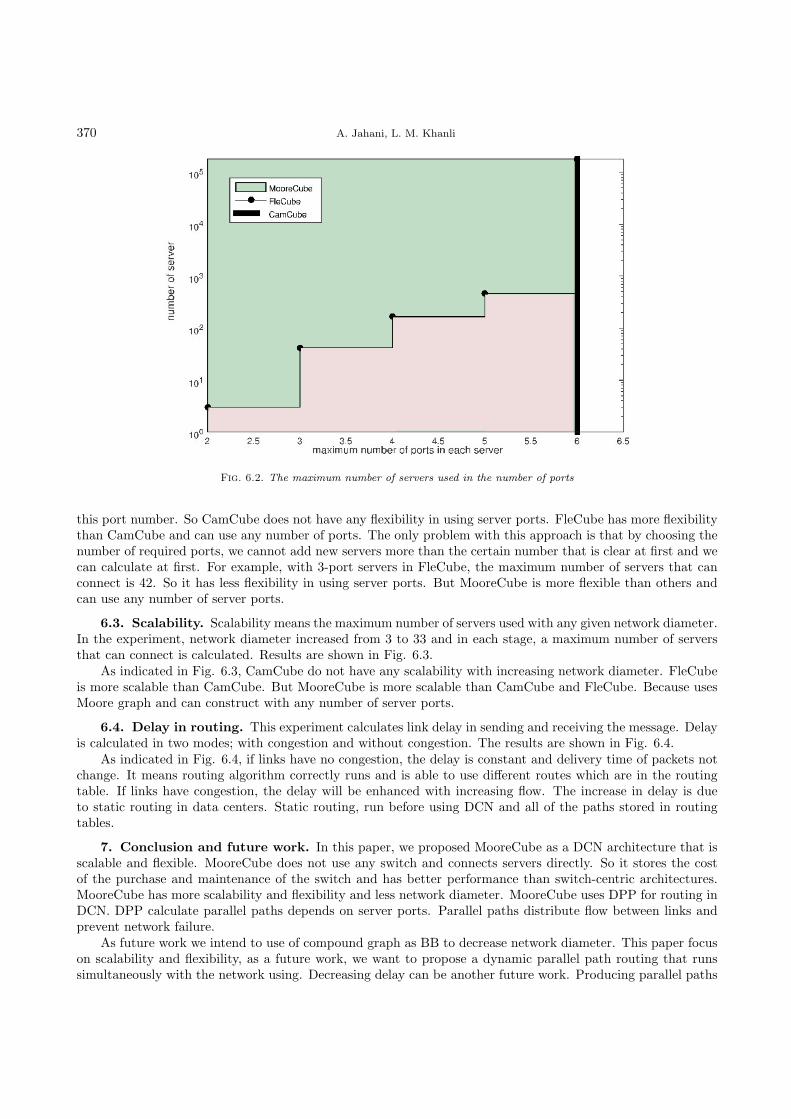
6.2. Flexibility. Flexibility means useing of architecture with any number of ports in the server and thearchitecture must not depend on port and should be usable regardless of server ports. MooreCube is constructivewith any number of server ports. This experiment shows MooreCube flexibility in compress of FleCube andCamCube. This experiment measures the maximum number of servers that each strategy can connect with aspecified port number. The experiment results are shown in Fig. 6.2.
As indicated in the Fig. 6.2, CamCube use only 6-port servers and can connect any number of servers with
Fig. 6.1. Network diameter (6-ports server)
370 A. Jahani, L. M. Khanli
Fig. 6.2. The maximum number of servers used in the number of ports
this port number. So CamCube does not have any flexibility in using server ports. FleCube has more flexibilitythan CamCube and can use any number of ports. The only problem with this approach is that by choosing thenumber of required ports, we cannot add new servers more than the certain number that is clear at first and wecan calculate at first. For example, with 3-port servers in FleCube, the maximum number of servers that canconnect is 42. So it has less flexibility in using server ports. But MooreCube is more flexible than others andcan use any number of server ports.
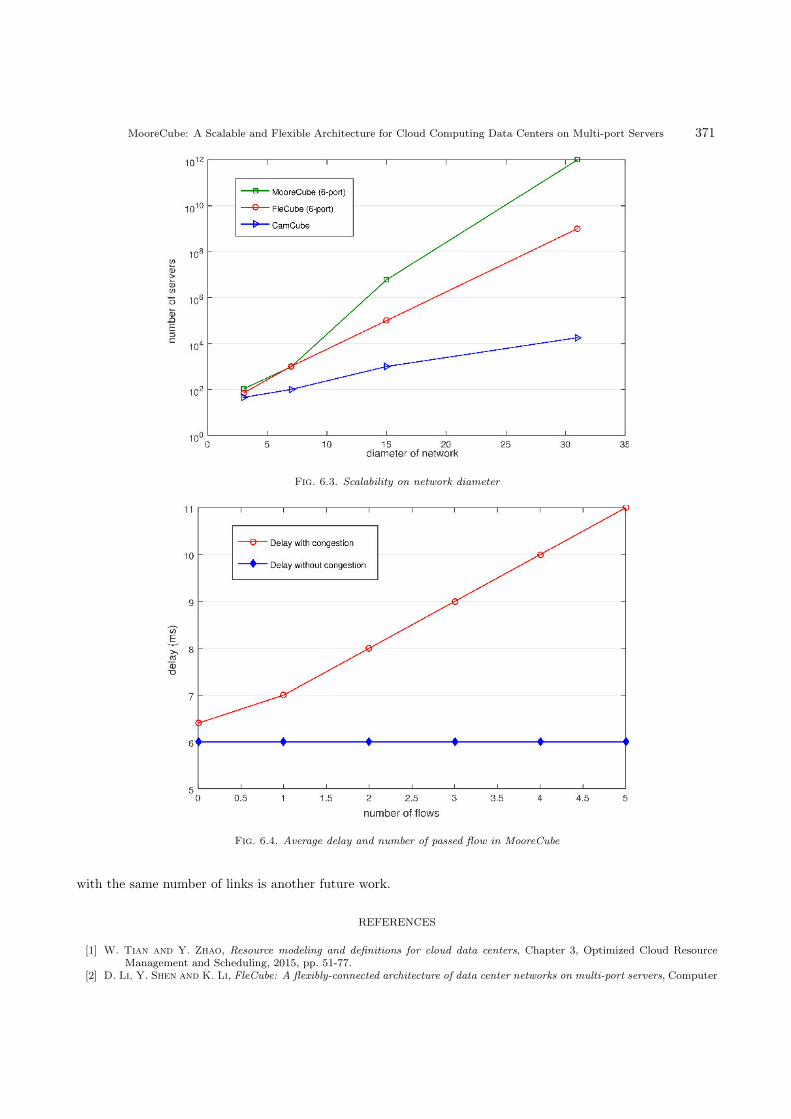
6.3. Scalability. Scalability means the maximum number of servers used with any given network diameter.In the experiment, network diameter increased from 3 to 33 and in each stage, a maximum number of serversthat can connect is calculated. Results are shown in Fig. 6.3.
As indicated in Fig. 6.3, CamCube do not have any scalability with increasing network diameter. FleCubeis more scalable than CamCube. But MooreCube is more scalable than CamCube and FleCube. Because usesMoore graph and can construct with any number of server ports.
6.4. Delay in routing. This experiment calculates link delay in sending and receiving the message. Delayis calculated in two modes; with congestion and without congestion. The results are shown in Fig. 6.4.
As indicated in Fig. 6.4, if links have no congestion, the delay is constant and delivery time of packets notchange. It means routing algorithm correctly runs and is able to use different routes which are in the routingtable. If links have congestion, the delay will be enhanced with increasing flow. The increase in delay is dueto static routing in data centers. Static routing, run before using DCN and all of the paths stored in routingtables.
7. Conclusion and future work. In this paper, we proposed MooreCube as a DCN architecture that isscalable and flexible. MooreCube does not use any switch and connects servers directly. So it stores the costof the purchase and maintenance of the switch and has better performance than switch-centric architectures.MooreCube has more scalability and flexibility and less network diameter. MooreCube uses DPP for routing inDCN. DPP calculate parallel paths depends on server ports. Parallel paths distribute flow between links andprevent network failure.
As future work we intend to use of compound graph as BB to decrease network diameter. This paper focuson scalability and flexibility, as a future work, we want to propose a dynamic parallel path routing that runssimultaneously with the network using. Decreasing delay can be another future work. Producing parallel paths
MooreCube: A Scalable and Flexible Architecture for Cloud Computing Data Centers on Multi-port Servers 371
Fig. 6.3. Scalability on network diameter
Fig. 6.4. Average delay and number of passed flow in MooreCube
with the same number of links is another future work.
REFERENCES
[1] W. Tian and Y. Zhao, Resource modeling and definitions for cloud data centers, Chapter 3, Optimized Cloud ResourceManagement and Scheduling, 2015, pp. 51-77.
[2] D. Li, Y. Shen and K. Li, FleCube: A flexibly-connected architecture of data center networks on multi-port servers, Computer

372 A. Jahani, L. M. Khanli
Communications, 70 (2015), pp. 1-10.[3] B. Wang, z. Qi, R. Ma, H. Guan and V. Vasilakos, A survey on data center networking for cloud computing, Computer
Networks, 91 (2015), pp. 528-547.[4] G. Wu, H. Gu, K. Wang, X. Yu and Y. Guo, A scalable AWG-based data center network for cloud computing, Optical
Switching and Networking, 16 (2015), pp. 46-51.[5] Y. Shen, K. Li, and W. Shi, Advanced topics on cloud computing, Journal of Computer and System Sciences, 79 (2013), pp.
1199, 2013.[6] T. Wang, Z. Su, Y. Xia, J. Muppala and M. Hamdi, Designing efficient high performance server-centric data center
network architecture, Computer Networks, 79 (2015), pp. 283-296.[7] X. Yu, H. Gu, Y. Yang and K. Wang, RingCube An incrementally scale-out optical interconnect for cloud computing data
center, Future Generation Computer Systems, 54 (2016), pp. 41-51.[8] S. Fu, B. Wu, X. Jiang, A. Pattavina, H. Wen and H. Yu, Switch cost and packet delay tradeoff in data center networks
with switch reconfiguration overhead, Computer Networks, 87 (2015), pp. 33-43.[9] M. Uddin, Y. darabidarabkhani, A. Shah and J. Memon, Evaluating power efficient algorithms for efficiency and carbon
emissions in cloud data centers: A review, Renewable and Sustainable Energy Reviews, 51 (2015), pp. 1553-1563.[10] S. Filiposka and C. Juiz, Community-based complex cloud data center, Physica A: Statistical Mechanics and its
Applications, 419 (2015), pp. 356-372.[11] A. Erickson, A. Stewart, J. Navaridas and A. Kiasari, Star-replaced networks: A generalised class of dual-port server-
centric data center networks, Computer Networks, 2015, pp. 1-30.[12] M. Miller and J. Siran, Moore graphs and beyond A survey of the degreediameter problem, University of Newcastle, The
Electronic Journal of Combinatorics, 20 (2013), pp. 1-92.[13] E. Ducey, On the critical group of the missing Moore graph, Discrete Mathematics, 340 (2017), pp. 1104-1109.[14] T. Baker, B. Dawsari, H. Tawfik, D. Reid and Y. Ngoko, GreeDi: An energy efficient routing algorithm for big data on
cloud, Ad Hoc Networks, 35 (2015), pp. 83-96.[15] Z. Zhang, W. Hu, T. Ye, W. Sun, L. Zhao and K. Zhang, Routing and spectrum allocation in multi-ring based data center
networks, Optics Communications, 360 (2016), pp. 25-34.[16] M.A. Fares, A. Loukissas and A. Vahdat, A Scalable, commodity data center network architecture, Acm Sigcomm, 2008,
pp. 1-12.[17] R. Mysore, A. Pamboris, N. Farrington, N. Huang, P. Miri, S. Radhakrishnan, V. Subramanya and A. Vahdat,
PortLand: A Scalable Fault-Tolerant, Sigcomm Proceedings of the ACM Sigcomm, Conference on Data Communication,Newyork, USA, 2009, pp. 39-50.
[18] A. Greenberg, J. Hamilton and N. Jain, VL2: a scalable and flexible data center network, Sigcomm Proceedings of TheACM Sigcomm, Conference on Data Communication, New York, USA, 2009, pp. 51-62.
[19] A. Singla, Ch. Hong, L. Popa and B. Godfrey, Jellyfish: networking data centers randomly, NSDI’12 Proceedings of the9th USENIX Conference on Networked Systems Design and Implementation, Berkeley, USA, 2012, pp. 1-6.
[20] Y. Yu and C. Qian, Space Shuffle: a scalable, flexible and high bandwidth data center network, ICNP ’14 Proceeding of the2014 IEEE 22nd International Conference on Network Protocols, 2014, pp. 13-24.
[21] L. Gyarmati and T. Trinh, Scafida: a scale-free network inspired data center, ACM Sigcomm Computer CommunicationReview, 40 (2010), pp. 4-12.
[22] M. Csernai, A. Gulyas, A. Korosi, B. Sonkoly and G. Biczok, Incrementally upgradable data center architecture usinghyperbolic tessellations, Computer Networks, 57 (2013), pp. 1373-1393.
[23] J. Shin, B. Wong and E. Sirer, Small-World Datacenters, SOCC ’11 Proceedings of the 2nd ACM Symposium on CloudComputing, Newyork, USA, 2011, pp. 1-13.
[24] C. Guo, H. Wu, K. Tan, L. Shi, Y. Zhang and S. Lu, DCell: A Scalable and Fault-Tolerant Network, ACM SigcommComputer Communication Review, 38 (2008), pp. 75-86.
[25] C. Guo, G. Lu, D. Li, L. Wu, X. Zhang and Y. Shi, BCube: A high performance, Server-centric Network, ACM SigcommComputer Communication Review, 39 (2009), pp. 63-74.
[26] D. Li, H. Wu, K. Tan, Y. Zhang and S. Lu, FiConn: using backup port for server interconnection in data centers, IEEEInfocom, 2009, pp. 2276- 2285.
[27] D. Lin, Y. Liu, M. Hamdi and J. Muppala, FlatNet: towards a flatter data center network, Globecom Next GenerationNetworking and Internet Symposium, 2012, pp. 2499-2504.
[28] D. Guo, T. Chen, D. Li, M. Li, Y. Lio and G. Chen, Expandable and cost-effective network structures for data centersusing dual-port servers, IEEE Transaction on Computers, 62 (2013), pp. 1303-1317.
[29] Y. Liao, J. Yin, D. Yin and L. Gao, DPillar: dual-port server interconnection network for large scale data centers, ComputerNetworks, 56 (2012), pp. 2132-2147.
[30] D. Li and J. Wu, On the design and analysis of Data Center Network architectures for interconnecting dual-port servers,Infocom IEEE Conference on Computer Communication, 2014, pp. 1851-1859.
[31] Li, Deshun, Yanming Shen, and Keqiu Li, FleCube: A flexibly-connected architecture of data center networks on multi-portservers, Computer Communications 77 (2016): 62-71.
[32] A. Gawanmeh,, and A. Alomari, Challenges in formal methods for testing and verification of cloud computing systems,Scalable Computing: Practice and Experience, 16 (2015): 321-332.
[33] D. Guo, C. Li, J. Wu and X. Zhou, DCube: A family of network structures for containerized data centers using dual-portservers, Computer Communications, 53 (2014), pp. 13-25.
[34] D. Li, J. Wu, Z. Liu and F. Zhang, Dual–centric data center network architectures, in Proceedings of IEEE ICPP 15, 2015.[35] T. Wang, Z. Su, Y. Xia, J. Muppala and M. Hamdi, SprintNet: A high performance server-centric network architecture

MooreCube: A Scalable and Flexible Architecture for Cloud Computing Data Centers on Multi-port Servers 373
for data centers, Computer Networks, 79 (2015), pp. 283-296.[36] H. Libdeh, P. Costa, A. Rowstorn, G. Shea and A. Donnelly, cam cube: symbiotic routing in future data centers, ACM
Sigcomm Computer Communication Review, 40 (2010), pp. 51-62.[37] T. Wang, Z. Su, Y. Xia, B. Qin and M. Hamdi, NovaCube: A low latency torus-based network architecture for data centers,
IEEE Global Communications Conference (Globecom), Austin, TX, 2014, pp. 2252-2257.[38] A. Hoffman and R. Singleton, On Moore graphs of diameter 2 and 3, IBM Journal of Research and Development, 4 (1960),
pp. 497-504.
Edited by: Amjad GawanmehReceived: Jul 1, 2017Accepted: Oct 27, 2017