Embed Size (px)
Citation preview

CHAPTERCHAPTERCHAPTERCHAPTER 1111 BACKGROUNDBACKGROUNDBACKGROUNDBACKGROUND OFOFOFOF THETHETHETHE PROJECTPROJECTPROJECTPROJECT
1-5
Figure 1-3 Locations of Weather Station (left) and Annual Rainfall Distribution (right)
Table 1-2 Observation Periods of Collected Data of Each Weather Station
Name of the Weather Stations
Elevations (m)
Annual Rainfall (mm) Period
Katimok 2,286 1415 1983-2009 Kabarnet 2,042 1340 1995-2005 Nakuru 1,901 967 1995-2010 Barwasa 1,676 884 1983-2010 Snake farm 975 755 1984-2010 Nginyang 914 541 1983-1996 Kapedo 762 497 1983-2000
Monthly Rainfall
0255075
100125150175200225250275
1 2 3 4 5 6 7 8 9 10 11 12
Month
Rainfall (m
m/m
onth)
Katimok
Kabarunet
Nakuru
Barwesa
Snake Farm
Nginyang
Kapedo
Figure 1-4 Monthly Rainfall Variation in the Project Area
These Figures and Table show the following tendencies:
• Monthly rainfall is larger from April to August, and smaller from December to February.
• Rainy season starts in March.
• November has a little bit larger rainfall than October.
• Annual rainfall in the highland area is larger than in the lowland area, which means that annual
rainfall in Tugen Hills is larger than those in lowland areas such as Marigat and Chemolingot.
• Southern sub-basins have larger annual rainfall than the northern sub-basins in the project area.
b. Air Temperature
Monthly averages of daily maximum and minimum air temperature at Nakuru Weather Station are as
shown in Figure 1-5. The observation period of collected data is from 1996 to 2009. The data shows that

CHAPTERCHAPTERCHAPTERCHAPTER 1111 BACKGROUNDBACKGROUNDBACKGROUNDBACKGROUND OFOFOFOF THETHETHETHE PROJECTPROJECTPROJECTPROJECT
1-6
annual average of daily maximum air temperature is 26°C, and annual average of daily minimum air
temperature is 12°C. Monthly change of daily maximum air temperature is higher in January to March and
lower in July, and monthly change of daily minimum temperature is higher in April to May and lower in
December to February. However, the difference among the air temperatures is small.
0
5
10
15
20
25
30
35
Jan Feb Mar Apr May Jun Jul Aug Sep Oct Nov Dec
Month
Tem
perature (℃
)
Daily Maximum
Daily Minimum
Figure 1-5 Monthly Change of Daily Maximum and Minimum Air
Temperature
c. Sunshine Hours
Monthly averages of daily sunshine hours at Nakuru Weather Station are as shown in Figure 1-6. The
observation period of collected data is from 1996 to 2009. The data shows that annual average of daily
sunshine hours is about 7.5 hours, and the months from December to March and May to September have
longer sunshine hours (more than 7 hours). On the other hand, sunshine hours are less than 6 hours in
November. It should be noted that there are many months with no observation data.
Sunshine Hours
0
1
2
3
4
5
6
7
8
9
10
Jan Feb Mar Apr May Jun Jul Aug Sep Oct Nov Dec
Month
Daily Sunshine Hours
Figure 1-6 Monthly Change of Sunshine Hours
d. Wind Speed

CHAPTERCHAPTERCHAPTERCHAPTER 1111 BACKGROUNDBACKGROUNDBACKGROUNDBACKGROUND OFOFOFOF THETHETHETHE PROJECTPROJECTPROJECTPROJECT
1-7
Monthly averages of daily wind speed at Nakuru Weather Station are as shown in Figure 1-7. The
observation period of collected data is from 1996 to 2009. The data shows that annual average of wind
speed is about 3.1 m/sec. Wind speed is higher from December to May; however, the difference is small
and wind speed is slow throughout the year.
Wind Speed
0.0
0.5
1.0
1.5
2.0
2.5
3.0
3.5
4.0
4.5
5.0
Jan Feb Mar Apr May Jun Jul Aug Sep Oct Nov Dec
Month
Wind Speed (m
/sec)
Figure 1-7 Monthly Change of Wind Speed
1-2-2 Topography
Kenya is located at the east coast of the
African Continent and the equator crosses the
country. It has a variety in topographical
features such as glaciated high mountains, the
Great Rift Valley abundant in faults and
volcanoes, hilly highland, plain dessert and
coastal landform. The project area is located in
the Great Rift Valley.
Figure 1-8 shows the boundary and
topography of the project area. The
topographical characteristics of the area are
governed by the Great Rift Valley System
which extends to the north–south direction, and
the distinctive features are classified to
highland areas and low-lying areas. The
highlands are the Mochongai (Laikipia)
escarpments, the Tugen hills (Kamasia block),
the Elgeyo escarpments and the Uasin Gishu
highland from east to west of the project area.
Figure 1-8 Topography of the Project Area
Laikip
ia e
scarp
ment
Marigat
lowland
East Pokot
lowland
Tugen hills
Elge
yoesca
rpm
ent
U
asin G
ishu h
ighland
Kerio
lowland

CHAPTERCHAPTERCHAPTERCHAPTER 1111 BACKGROUNDBACKGROUNDBACKGROUNDBACKGROUND OFOFOFOF THETHETHETHE PROJECTPROJECTPROJECTPROJECT
1-8
Low-lying areas such as Marigat lowland, East Pokot lowland and Kerio lowland lie among them.
One of the other characteristics is the existence of lakes: Lake Bogoria is located at south of Marigat
lowland, and Lake Baringo is in the Marigat lowland. Both lakes are located at the lowest part of each
internal drainage basin. Another characteristic is the existence of newly formed volcanoes such as Korosi,
Paka and Silali in the East Pokot lowland. These three volcanoes were formed in Quaternary Era, and are
expected for geothermal exploitation.
1-2-3 Geology
(1) Geology of Kenya
The geology of Kenya consists of Pre-Cambrian, Paleozoic, Mesozoic and Cenozoic rocks and
sediments. The geology of Pre-Cambrian belongs to the Mozambique belt. It covers large parts of central
and west Kenya, and some of northeast Kenya. The Mozambique belt falls generally into three systems
called as the Nyanzian-Kavirondian system, Basement system and Bukoban system from the old system in
order. Among these, the Basement system occupies a large portion of Pre-Cambrian in Kenya. The
Basement system was thought as base rock in Kenya in the past; however, in the second half of 1966, it
became apparent that the Basement system was formed in a newer period than the Nyanzian and
Kavirondian systems.
Paleozoic and Mesozoic sedimentary rocks are distributed in northeast and southeast areas of Kenya.
These consist of two kinds of rock: one is a peculiar terrestrial deposit correlated with the Karoo system
formed from late Paleozoic to early Mesozoic, the other is a marine deposit such as limestone and
sandstone formed from Jurassic to Cretaceous.
The geology of Cenozoic consists of volcanic rocks (mainly distributed in the Great Rift Valley) and
sedimentary rocks (distributed in a belt continuing to the coast at the east side and around Lake Turkana).
Lithological character of intrusive rocks widely changes from acidic to ultra-basic rocks. Intrusive rocks
were main products by igneous activities during pre-synorogenic and synorogenic stages, and the rocks are
more or less metamorphosed.
On the other hand, there are non-metamorphosed intrusive rocks which formation might be during late
synorogenic stage to post synorogenic stage. These intrusive rocks exist as forms of rock sheets, stocks, and
dikes. Large scale rock bodies such as batholith were not recognized.
Volcanic rocks were formed with movements of the Great Rift Valley, and it began from activities of
basalt during Miocene, and it accompanied eruptive activities of nephelinite and carbonatite in Kenya. In
addition, at late Miocene, fissure eruptions formed lava plateaus of phonolites, and also formed
trachy-welded tuff. Caldera formation with volcanic activities continued even in Quaternary era.

CHAPTERCHAPTERCHAPTERCHAPTER 1111 BACKGROUNDBACKGROUNDBACKGROUNDBACKGROUND OFOFOFOF THETHETHETHE PROJECTPROJECTPROJECTPROJECT
1-9
Sedimentary rocks consist of marine sand of Tertiary era and sand/coral reef of Quaternary era at
eastside, and lacustrine sediment during late Miocene to Pliocene around Lake Turkana. (Source: METAL
MINING AGENCY OF JAPAN, 1984)
(2) Geology of the Project Area
The geology of the project area consists of: the basement system of Pre-Cambrian; phonolites,
trachytes, basalts of Miocene and Pliocene; trachytes, basalts, pyroclastics of Pleistocene; colluvial and
flood deposits of Holocene.
Figure 1-10 shows the outline of geology of the project area. The project area is almost located in the
Great Rift Valley, and the movement formed many faults in north-south and east-west directions.
!
!
!
!
MarigatKabarnet
Kabartonjo
Chomolingot
36°20'0"E
36°20'0"E
36°0'0"E
36°0'0"E
35°40'0"E
35°40'0"E
1°
20'0"N
1°
20'0"N
1°
0'0"N
1°
0'0"N
0°
40'0"N
0°
40'0"N
0°
20'0"N
0°
20'0"N
Study Area4 0 10 20 30 405km
Figure 1-9 Geology of the Project Area

CHAPTERCHAPTERCHAPTERCHAPTER 1111 BACKGROUNDBACKGROUNDBACKGROUNDBACKGROUND OFOFOFOF THETHETHETHE PROJECTPROJECTPROJECTPROJECT
1-10
Table 1-3 Stratigraphic Classification of the Project Area
Geological age Symbol of Geology
Rocks and Sediments facies
Holocene
Colluvial deposits、red soils、 lacustrine deposits、and flood deposits; these deposits are distributed in lowland. Red sols along Kerio river, lacustrine deposits in lowland. Colluvial deposits at the end of hilly area, food deposits along rivers. Quaternary
Pleistocene
Trachytes, basalts, pyroclastics. Representative rocks are Baringo trachytes and Baringo basalts, and these geologies can be seen at west side of Lake Baringo.
Intrusive rocks.
Pliocene
Trachytes, phonolites, basalts, and sedimentary rocks interleaved in igneous rocks. Representative geology is Kabarnet trachytes, which can be seen around Kabarnet.
Cenozoic
Neogine
Miocene
Trachytes, phonolites, basalts, and sedimentary rocks interleaved in igneous rocks. Representative geology is Samburu Basalt, which is widely distributed around Laikipia and Tugen hills. . .
Pre Cambrian
Mozambique belt (Basement system). The source rocks were sand, clay and limestone, and those were metamorphosed to gneiss, schist and marble stone.
1-2-4 Hydrogeology
(1) Distribution of Springs
Existing spring data are provided from the counterpart team, and the locations are as described in the
following figures with topological map and rainfall distribution maps.

CHAPTERCHAPTERCHAPTERCHAPTER 1111 BACKGROUNDBACKGROUNDBACKGROUNDBACKGROUND OFOFOFOF THETHETHETHE PROJECTPROJECTPROJECTPROJECT
1-11
Figure 1-9 Distribution of Existing Springs
The figures show that springs are distributed around Tugen Hills which have a large amount of annual
rainfall, and most of the springs are on the west slope of Tugen Hills. The reason is supposed to be that
geological layers in Tugen Hills incline westward so that infiltrated rainfall reaching the aquifers flow
westward along declined layers.
(2) Yields and Depths of Existing Wells ant Relation with Topography
Yields and depths of the existing wells are shown on the Topographic Map in the following figures.

CHAPTERCHAPTERCHAPTERCHAPTER 1111 BACKGROUNDBACKGROUNDBACKGROUNDBACKGROUND OFOFOFOF THETHETHETHE PROJECTPROJECTPROJECTPROJECT
1-12
Figure 1-10 Yields (Left Fig.) and Depths (Right Fig.) of the Existing Wells on the Topographic Map
These figures indicate that:
• Southern Part of Kerio valley lowland: More than 3 m3/hour of yield is generally expected. There
are some wells with above 15 m3/hour of yield due to blessed topographic condition where the
water is easy to get together. The well depths are from 100m to 150m. Groundwater development
in this area is relatively easy in the project area.
• Northern Part of Kerio valley lowland: Less than 1.5 m3/hour of yield is expected. The well
depths are from 75m to 150m.
• Ridge and Western Slope of Tugen Hills: 2.5 to 20 m3/hour of yield is expected. The dispersion
of yield by wells is very large. The well depths are from 100m to 200m. Dry wells are also
distributed. Therefore it needs for groundwater development to carefully select well drilling
points. The possibility of groundwater development in this area are middle, however, finding
suitable points for new wells in the requested sites are not always possible.
• Eastern Slope of Tugen Hills: The slope is very steep so that few existing wells are distributed.
• Southern Part (Hilly area, Plateau and Fan deposit area) of the East side of the Tugen Hills
(South of the sub-basin): Dry wells or wells with less 0.6m3/hour of yield are distributed in the

CHAPTERCHAPTERCHAPTERCHAPTER 1111 BACKGROUNDBACKGROUNDBACKGROUNDBACKGROUND OFOFOFOF THETHETHETHE PROJECTPROJECTPROJECTPROJECT
1-13
area which is close to the east side of steep slope of Tugen hills. The well depths are from 56m to
200m. On the other hand, wells in hilly and fan deposit area close to Marigat lowland generally
have yield of 1 - 3m3/hour and the well depth are 35m to 120m. In addition, wells located in
suitable condition sometimes have yield of 5 to 15m3/hour and the depths are 40m to 155m.
Depth of wells at the plateau area is getting deep.
• Hilly Area of the East side of the Tugen Hills (North of the sub-basin): Wells with 0.6 to
2..7m3/hour of yield and dry wells are distributed in the area which is close to the east side of
steep slope of Tugen hills. The well depths are from 50m to 110m. Rain runoff is very rapid so
that it may have few recharges to groundwater. On the other hand, the runoff from Tugen hills
concentrate to lowland which is stretched to north-south direction and close to East Pokot
lowland. The wells in the lowland have yield of 5 to 10m3/hour, and the well depths are around
80m to 120m.
• Marigat Lowland (Sedimentary deposit area: lowland): Marigat lowland is a sedimentary deposit
areas between Lake Baringo and Lake Bogoria, and of east of Lake Baringo. The wells in the
lowland have yield of 0.7 to 4m3/hour, and the well depths are around 20m to 60m. The wells
distributed in the area where the groundwater being easy to concentrate, have yield of 9m3/hour
or more, and the well depths are 40m to 70m.
• Plateaus around Marigat Lowland: Volcanic rocks formed in Quaternary era are predominantly
distributed in this area. The well yields are almost zero, or 0.5m3/hour or less. The well depths
are 90 to 120m.
• East Pokot Lowland: Volcanoes (Korosi, Paka and Silali) formed in Quaternary era are
distributed in this area. The depths of existing wells are 100m to 145m; however large numbers
of the wells are dry. Some wells which fortunately met localized groundwater have yield of about
2m3/hour, and the depths are around 90m to 120m.
• Mochongai Hills and Mochongai Escarpment: The yields of existing wells distributed in this area
are around zero to 0.95m3/hour; and the well depths are 75m to 150m. Finding groundwater is
very difficult in the area because the watershed of the area is very small along the escarpment
and groundwater resource is small, however some wells fortunately have yields of 2.5 to
6m3/hour and the depths are 45m to 85m.
(3) Yield and Depth of Existing Wells (Relation with Geology)
Yields and depths of collected existing wells are summarized in the following figures.
CHAPTERCHAPTERCHAPTERCHAPTER 1111 BACKGROUNDBACKGROUNDBACKGROUNDBACKGROUND OFOFOFOF THETHETHETHE PROJECTPROJECTPROJECTPROJECT
1-14
Figure 1-11 Yield (Left Figure) and Depth (Right Figure) of Existing Wells
on the Geological Map
At rock distributed areas, groundwater aquifers to be developed are those in fault fracture zone, void
in pyroclastics and cracks developed around boundaries of geological layers. At unconsolidated sediment
layer distributed areas, groundwater aquifers are sand layers, gravel layers and cracks of rocks below the
sediment layers.
As for the difference of well yield, the figures roughly show that the topography (about rainfall
distribution) has stronger relation than the geological features. In addition, wells in lowlands consisting of
volcanic rocks formed at Quaternary era have smaller yield than the others.
The target aquifers in each area are the following:
• Kerio Valley Lowland: Sediment layer, fractured zone and crack zones in rocks below sediment
layers.
• Ridge and Western Slope of Tugen Hills: Fault fracture zone, crack zones in rocks (especially
developed around boundaries of geological layers), and pyroclastics.
• Eastern Slope of Tugen Hills: Fault fracture zone, crack zones in rocks (especially developed
around boundaries of geological layers), and pyroclastics.

CHAPTERCHAPTERCHAPTERCHAPTER 1111 BACKGROUNDBACKGROUNDBACKGROUNDBACKGROUND OFOFOFOF THETHETHETHE PROJECTPROJECTPROJECTPROJECT
1-15
• Southern Part (Hilly area, Plateau and Fan deposit area) of the East side of the Tugen Hills
(South of the sub-basin): Colluvial deposits, fan deposits, fault fracture zone, crack zones in
rocks (especially developed around boundaries of geological layers), and pyroclastics.
• Hilly Area of the East side of the Tugen Hills (North of the sub-basin): Fault fracture zone, crack
zones in rocks (especially developed around boundaries of geological layers), and void in
pyroclastics at hilly area near steep slope of Tugen hills; sediment layers is added to the target
aquifers in low land which stretched to north-south direction located at eastern part of the hilly
area above mentioned.
• Marigat lowland (Sedimentary deposit area: lowland): Sediment layers, colluvial deposits, crack
zones of rocks below the sediment layers, and pyroclastics.
• Plateaus around Marigat Lowland: Fault fracture zone, crack zones in rocks, and pyroclastics.
• East Pokot Lowland: Fault fracture zone, crack zones in rocks, pyroclastics, and sediment layers
(at particular area).
• Mochongai hills and Mochongai escarpment: Fault fracture zone, crack zones in rocks
(especially developed around bed boundaries), and pyroclastics.
1-2-5 Groundwater Table
Groundwater tables of the existing wells are summarized and shown on the Topographic Map (left
Figure) and Geological Map (right Figure) shown below.
CHAPTERCHAPTERCHAPTERCHAPTER 1111 BACKGROUNDBACKGROUNDBACKGROUNDBACKGROUND OFOFOFOF THETHETHETHE PROJECTPROJECTPROJECTPROJECT
1-16
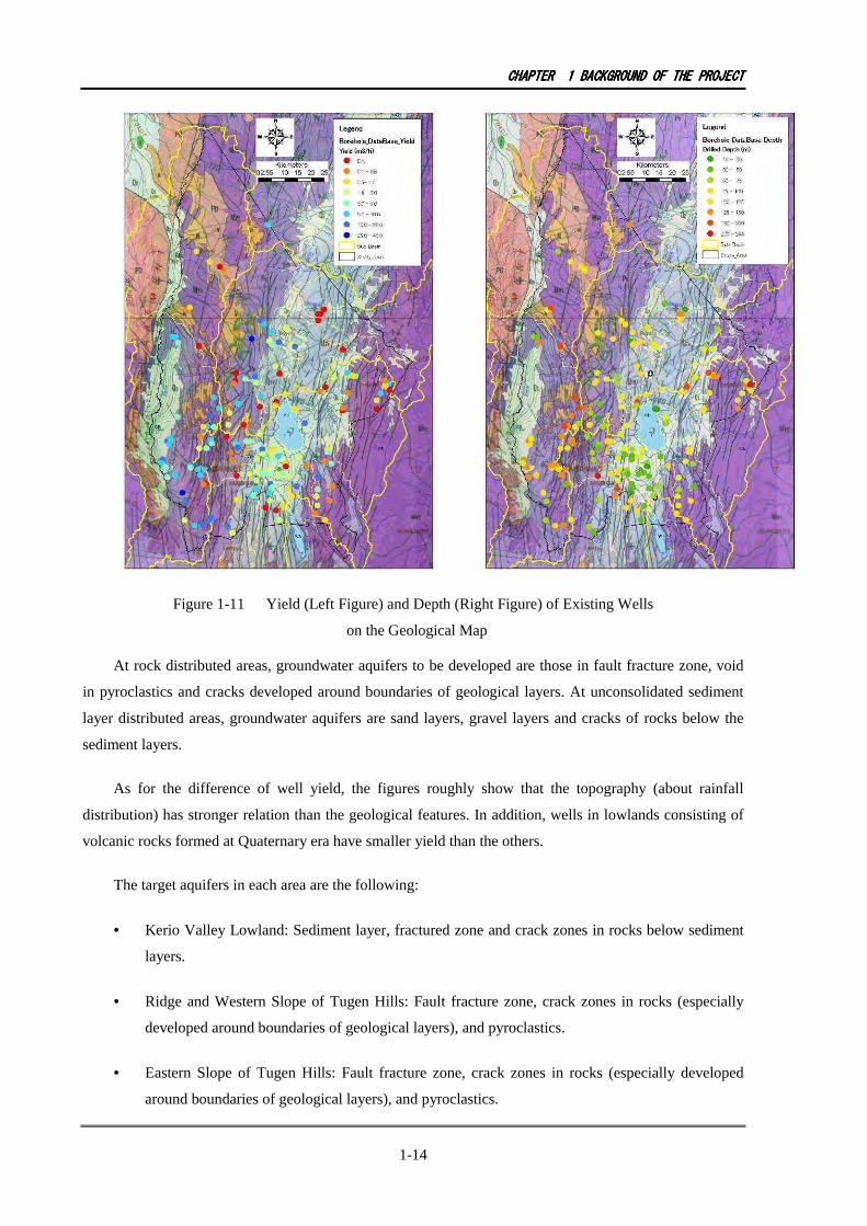
Figure 1-12 Depth Distribution of Groundwater Table of the Existing Wells
Groundwater tables in each area are summarized below based on the above figures.
• Kerio Valley Lowland: around 30m to 40m.
• Ridge and Western Slope of Tugen Hills: Around 30m to 125m. The depths of the groundwater
tables vary widely in this area.
• Eastern Slope of Tugen Hills: Almost no existing wells are distributed in this area so that the
groundwater tables are not known.
• Southern Part (Hilly area, Plateau and Fan deposit area) of the East side of the Tugen Hills
(South of the sub-basin): Around 50m to 60m.
• Hilly Area of the East side of the Tugen Hills (North of the sub-basin): Around 20m to 80m. The
depths of the groundwater tables vary widely in this area.
• Marigat Lowland (Sedimentary deposit area: lowland): Around 20m to 35m.
• Plateaus around Marigat Lowland: Around 35m to 95m. The depths of the groundwater tables
vary widely in this area.

CHAPTERCHAPTERCHAPTERCHAPTER 1111 BACKGROUNDBACKGROUNDBACKGROUNDBACKGROUND OFOFOFOF THETHETHETHE PROJECTPROJECTPROJECTPROJECT
1-17
• East Pokot Lowland: Around 60m to 110m. The groundwater table is deep despite the wells are
distributed in lowland area.
• Mochongai Hills and Mochongai Escarpment: Only one existing data is obtained, and the
groundwater table is around 55m.
1-2-6 Water Quality
(1) Water Quality Standards
Kenya has two kinds of drinking water standards. One is written in “DRINKING WATER QUALTY
AND EFFLUENT MONITORING GUIDELINE (Water Service Regulatory Board)”. The other is in
“PRACTICE MANUAL FOR WATER SUPPLY SERVICES IN KENYA.” The items and regulation
values are summarized in the tables below with the guideline values of corresponding water quality items
of WHO Guideline 2004. It should be noted that some items in both Kenyan Standards have desirable and
permissible values.

CHAPTERCHAPTERCHAPTERCHAPTER 1111 BACKGROUNDBACKGROUNDBACKGROUNDBACKGROUND OFOFOFOF THETHETHETHE PROJECTPROJECTPROJECTPROJECT
1-18
Table 1-4 Drinking Water Quality Regulation Values among Kenyan Standards and WHO Guideline
Kenyan Standard Manual
Water Quality Analysis
Items Unit
Guideline Desirable Permissible
WHO(2004)
1 Colour TCU 15 50 --- 2 Taste and odour --- Shall not be offensive to consumers --- 3 Suspended matter --- Nil --- 4 Turbidity NTU 5 25 --- 5 TDS mg/L 1500 1000 (1984) 6 Hardness as CaCO3 500 --- 7 Aluminum as A1 0.1 0.2 (1984) 8 Chloride as Cl- 250 600 250 (1984) 9 Copper as Cu 0.1 1.5 2 10 Iron mg/L 0.3 1.0 0.3 (1984) 11 Manganese mg/L 0.1 0.5 0.4 12 Sodium as Na mg/L 200 200 (1984) 13 Sulphate as SO4 mg/L 400 500(recommended) 14 Zinc as Zn mg/L 5 15 5 (1984) 15 PH 6.5 – 8.5 6.5 – 9.2 --- 16 Magnesium as Mg mg/L 100 --- 17 Chlorine concentration mg/L 0.2 - 0.5 5 18 Calcium as Ca mg/L 250 --- 19 Ammonia (N) mg/L 0.5 --- 20 Fluoride mg/L 3.0 (1.5) 1.5 1.5 21 Arsenic mg/L 0.05 0.01 22 Cadmium as Cd mg/L 0.005 0.003 23 Lead as Pb mg/L 0.05 0.01 24 Mercury (total Hg) mg/L 0.001 0.006 25 Selenium as Se mg/L 0.01 0.01 26 Chromium as Cr mg/L 0.05 0.05 27 Cyanide as CN mg/L 0.01 0.07 28 Phenolic substances mg/L 0.002 --- 29 Barium as Ba mg/L 1.0 0.7 30 Nitrate as NO3 mg/L 10 50
Note) The values in the Table with “(1984)” means that guideline values did not established in the WHO Guideline after 1984 due to small effects of the items to human health. As for Fluoride, “DRINKING WATER QUALTY AND EFFLUENT MONITORING GUIDELINE” has explanatory note, and it says “the local and climatic conditions necessitate adaptation of Fluoride concentration in excess of 1.5 mg/L. In exceptional cases, a Fluoride content of 3mg/L can be acceptable in Kenya.”
Items in Kenyan standards have lax regulation values than the one in WHO Guideline.
Adopted regulation values in this project
The project is one of rural drinking water supply projects. The local and climatic conditions of the
project area are very severe so that the development of groundwater is very difficult to keep with regular
Kenyan standards of drinking water. Therefore, permissible values are adopted for the project in case the
Kenyan standards have the corresponding values. Blue colored cells in the table show the adopted
permissible values in the project.
(2) Total Dissolved Solid (TDS)
TDS data of existing wells were collected as summarized in the figures below. The figures show that
there are some wells in which TDS values of groundwater exceed the regulation value (1500 mg/L). They

CHAPTERCHAPTERCHAPTERCHAPTER 1111 BACKGROUNDBACKGROUNDBACKGROUNDBACKGROUND OFOFOFOF THETHETHETHE PROJECTPROJECTPROJECTPROJECT
1-19
are the 2 wells around Lake Baringo, 6 wells in Marigat lowland, 1 well at southern plateau of Marigat
lowland, and 2 wells in East Pokot.
Figure 1-13 TDS Concentration of Groundwater in Existing Wells
The area around Lake Baringo and Marigat lowland is in the depression zone, and they are also
located at the lowest reach of the sub-basin which has the hydrological structure of an internal drainage
basin, so that the main deposits of sedimentary layers are lacustrine deposits. The areas under semi-arid
climate have the general tendency of high evaporation, so that the groundwater in such areas may be rich in
minerals. Therefore, the groundwater in the lacustrine deposits of the area around Lake Baringo and
Marigat lowland is assumed to be rich in minerals and cause high TDS in the groundwater.
TDS values in groundwater satisfy the regulation values at a part of Marigat lowland near the southern
plateau. The reason may be the rapid groundwater recharge from Tugen hills, especially from the
highland area of the hills.
On the other hand, the causes mentioned above do not apply to the groundwater of the wells in the
plateaus located at the south of Marigat lowland and East Pokot where TDS exceed the regulation value.
One of the possible causes is the effect of volcanic activities of volcanoes during the Quaternary era such as
Volcano Korosi, Paka and Silali.
CHAPTERCHAPTERCHAPTERCHAPTER 1111 BACKGROUNDBACKGROUNDBACKGROUNDBACKGROUND OFOFOFOF THETHETHETHE PROJECTPROJECTPROJECTPROJECT
1-20
Lake Baring is expected to be a salt lake from this standpoint; however, it actually is a freshwater lake
with a high concentration of fluoride. The causes may be that the formation age of the lake is new, and/or
the lake water leaks to the downstream basin with minerals.
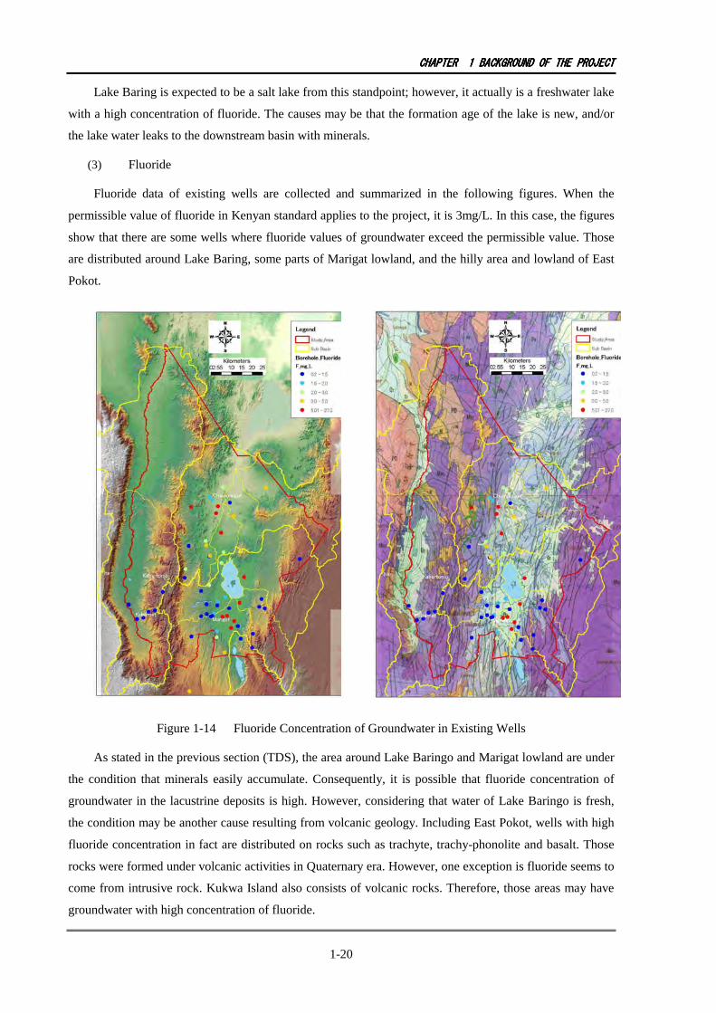
(3) Fluoride
Fluoride data of existing wells are collected and summarized in the following figures. When the
permissible value of fluoride in Kenyan standard applies to the project, it is 3mg/L. In this case, the figures
show that there are some wells where fluoride values of groundwater exceed the permissible value. Those
are distributed around Lake Baring, some parts of Marigat lowland, and the hilly area and lowland of East
Pokot.
Figure 1-14 Fluoride Concentration of Groundwater in Existing Wells
As stated in the previous section (TDS), the area around Lake Baringo and Marigat lowland are under
the condition that minerals easily accumulate. Consequently, it is possible that fluoride concentration of
groundwater in the lacustrine deposits is high. However, considering that water of Lake Baringo is fresh,
the condition may be another cause resulting from volcanic geology. Including East Pokot, wells with high
fluoride concentration in fact are distributed on rocks such as trachyte, trachy-phonolite and basalt. Those
rocks were formed under volcanic activities in Quaternary era. However, one exception is fluoride seems to
come from intrusive rock. Kukwa Island also consists of volcanic rocks. Therefore, those areas may have
groundwater with high concentration of fluoride.
CHAPTERCHAPTERCHAPTERCHAPTER 1111 BACKGROUNDBACKGROUNDBACKGROUNDBACKGROUND OFOFOFOF THETHETHETHE PROJECTPROJECTPROJECTPROJECT
1-21
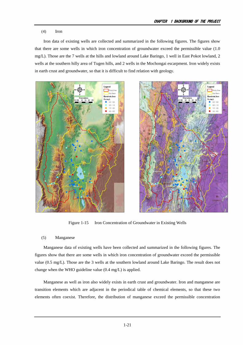
(4) Iron
Iron data of existing wells are collected and summarized in the following figures. The figures show
that there are some wells in which iron concentration of groundwater exceed the permissible value (1.0
mg/L). Those are the 7 wells at the hills and lowland around Lake Baringo, 1 well in East Pokot lowland, 2
wells at the southern hilly area of Tugen hills, and 2 wells in the Mochongai escarpment. Iron widely exists
in earth crust and groundwater, so that it is difficult to find relation with geology.
Figure 1-15 Iron Concentration of Groundwater in Existing Wells
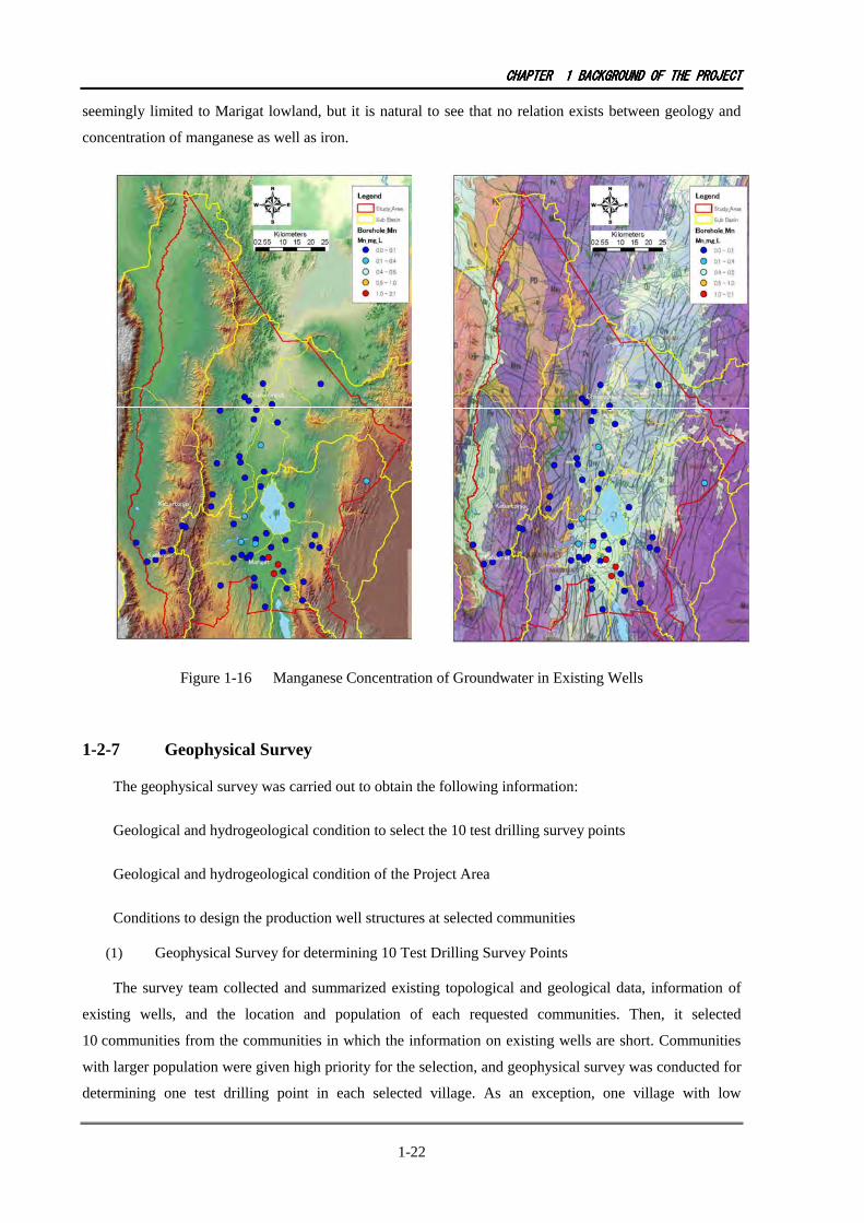
(5) Manganese
Manganese data of existing wells have been collected and summarized in the following figures. The
figures show that there are some wells in which iron concentration of groundwater exceed the permissible
value (0.5 mg/L). Those are the 3 wells at the southern lowland around Lake Baringo. The result does not
change when the WHO guideline value (0.4 mg/L) is applied.
Manganese as well as iron also widely exists in earth crust and groundwater. Iron and manganese are
transition elements which are adjacent in the periodical table of chemical elements, so that these two
elements often coexist. Therefore, the distribution of manganese exceed the permissible concentration
CHAPTERCHAPTERCHAPTERCHAPTER 1111 BACKGROUNDBACKGROUNDBACKGROUNDBACKGROUND OFOFOFOF THETHETHETHE PROJECTPROJECTPROJECTPROJECT
1-22
seemingly limited to Marigat lowland, but it is natural to see that no relation exists between geology and
concentration of manganese as well as iron.
Figure 1-16 Manganese Concentration of Groundwater in Existing Wells
1-2-7 Geophysical Survey
The geophysical survey was carried out to obtain the following information:
Geological and hydrogeological condition to select the 10 test drilling survey points
Geological and hydrogeological condition of the Project Area
Conditions to design the production well structures at selected communities
(1) Geophysical Survey for determining 10 Test Drilling Survey Points
The survey team collected and summarized existing topological and geological data, information of
existing wells, and the location and population of each requested communities. Then, it selected
10 communities from the communities in which the information on existing wells are short. Communities
with larger population were given high priority for the selection, and geophysical survey was conducted for
determining one test drilling point in each selected village. As an exception, one village with low
CHAPTCHAPTCHAPTCHAPTERERERER 1111 BACKGROUNDBACKGROUNDBACKGROUNDBACKGROUND OFOFOFOF THETHETHETHE PROJECTPROJECTPROJECTPROJECT
1-23
population was selected in Marigat lowland, because there are no communities with higher population but
whose grounds may have sedimentary aquifers with different fluoride concentrations.
There seems to be two kinds of aquifers in the project area: one is the fault fracture zone, and the other
is sedimentary layers, so that the application of number of HEP and VES were changed for the aquifer
types. In either case, firstly, site reconnaissance was conducted and, secondly, points with high
groundwater development potential were chosen from the hydrogeological point of view, and then
geophysical survey was conducted for the points.
[The Geophysical Survey for the Aquifer of Fault Fracture Zone]
As a rule, firstly, two HEPs were conducted at probable sites to know the exact location of faults.
Secondly, three VESs were conducted at each promising point to obtain geological profiling data in depth.
[The Geophysical Survey for the Aquifer of Sedimentary Layers]
Basically, three VESs were conducted at a promising site in the selected site.
[Exploration Methods]
Horizontal Electrical Profiling (HEP)
Electrode configuration: Wenner array
Number of exploration points: Two lines in each village.
Exploration depth: 30m
Length of survey line: around 200m
Vertical Electrical Sounding (VES)
Electrode configuration: Shlumberger array
Number of exploration points: 3 points in each selected village
Exploration depth: 200m
[The Result of Geophysical Survey]
The locations of the 10 communities selected are shown in the following figure. The number of
conducted geophysical surveys is shown in the following table.

CHAPTERCHAPTERCHAPTERCHAPTER 1111 BACKGROUNDBACKGROUNDBACKGROUNDBACKGROUND OFOFOFOF THETHETHETHE PROJECTPROJECTPROJECTPROJECT
1-24
Figure 1-17 Location of Ten Sites Selected
Table 1-5 Number of Explored Sites of Each Selected Village for the Test Drilling Survey
Code Selected Sites Location Division No. of HEP No. of VES 24 Toboroi Kinyach Bartabwa 2 3 110 Kapsikoryan Kiboino Salawa 2 2 131 Kabasis Kabasis Sacho 2 3 137 Kapkawa Ewalel Kabarnet 2 3 67 Lesuuwa Ng'ambo Marigat 0 3 86 Samuran Sandai Marigat 0 3 103 Kakwane Lelmen Salawa 0 3 153 Chebilat Loruk Mondi 1 3 185 Chesakam Ribko Nginyang 0 3 155 Naudo Naudo Mondi 0 1
Total 9 27
The estimated aquifer profile for selected test drilling points in each village selected is shown in the
following table using VESs. The detailed data of each VES are shown in the Appendix.

CHAPTERCHAPTERCHAPTERCHAPTER 1111 BACKGROUNDBACKGROUNDBACKGROUNDBACKGROUND OFOFOFOF THETHETHETHE PROJECTPROJECTPROJECTPROJECT
1-25
Table 1-6 Estimated Aquifer Profile at Selected Test Drilling Points by Geophysical Survey
Depth of Aquifer(m) Code
Selected Communities
Estimated Aquifer Resistivity(Ohm-m) Top Bottom
24 Toboroi Trachyphonolites, Basalts
20 46 ---
110 Kapsikoryan Trachyphonolites 120 8.3 130
131 Kabasis Trachyphonolites, Basalts
38 15 200
137 Kapkawa Trachyphonolites, Basalts 26 54 --- 67 Lesuuwa Basalts 12 11 45 - 70 86 Samuran Sediments, Basalts 40 65 --- 103 Kakwane Sediments, Basalts 22 16 231 153 Chebilat Pyroclastic rocks 18 140 ---
185 Chesakam Pyroclastics, basalts
20 61 ---
155 Naudo Basalts 50 94 ---
(2) Geophysical Survey for Design of Production Well and Obtaining Hydrogeological Data at
Selected Communities
Selecting 112 communities from 140 candidate communities, geophysical surveys were conducted to
get hydrogeological information and for design of production wells. When communities close to each other
were considered to have same hydrogeological condition, one VES was conducted at representative point in
the area. Selected 10 communities for test drilling survey were not included in 140 communities. The
geophysical survey for test drilling survey also can contribute to the purpose of this section.
[Exploration Methods]
Vertical Electrical Sounding (VES)
Electrode configuration: Shlumberger array
Number of exploration points: 1 point in each selected village
Exploration depth: 200m
As an exception, for Lomyek Village, one HEP and two VES were implemented because the village
was one of candidate site for test drilling survey.
[Result of Geophysical Survey]
The locations of 112 VESs are shown in the following table. The results are shown in the Appendix.

CHAPTERCHAPTERCHAPTERCHAPTER 1111 BACKGROUNDBACKGROUNDBACKGROUNDBACKGROUND OFOFOFOF THETHETHETHE PROJECTPROJECTPROJECTPROJECT
1-26
Figure 1-18 Locations of VES for Design of Production Well
and Hydrogeological Data obtained at Selected Communities
1-2-8 Test Drilling Survey
The survey team collected and summarized existing topological and geological data, information on
existing wells, and the location and population of each requested community, Then, it selected
10 communities in which information on existing wells is short. Communities with larger population were
given high priority for the selection, and geophysical survey was conducted for determining one test
drilling point in each selected village. As an exception, one village with low population was selected in
Marigat lowland, because there are no communities with higher population but whose grounds may have
sedimentary aquifers for surveying the difference of fluoride concentration in each aquifer.
CHAPTERCHAPTERCHAPTERCHAPTER 1111 BACKGROUNDBACKGROUNDBACKGROUNDBACKGROUND OFOFOFOF THETHETHETHE PROJECTPROJECTPROJECTPROJECT
1-27
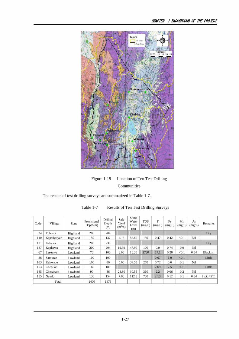
Figure 1-19 Location of Ten Test Drilling
Communities
The results of test drilling surveys are summarized in Table 1-7.
Table 1-7 Results of Ten Test Drilling Surveys
Code Village Zone Provisional Depth(m)
Drilled Depth (m)
Safe Yield (m3/h)
Static Water Level (m)
TDS (mg/L)
F (mg/L)
Fe (mg/L)
Mn (mg/L)
As (mg/L) Remarks
24 Toboroi Highland 200 204 Dry
110 Kapsikoryan Highland 150 132 4.16 56.80 130 0.47 0.42 <0.1 Nil
131 Kabasis Highland 200 230 Dry
137 Kapkawa Highland 200 204 19.39 47.90 100 0.0 0.74 0.0 Nil
67 Lesuuwa Lowland 70 100 3.00 18.30 2730 17.1 0.28 <0.1 0.04 Blackish
86 Samuran Lowland 100 100 0.67 1.9 <0.1 Little
103 Kakwane Lowland 100 86 5.60 39.55 270 0.72 0.6 0.1 Nil
153 Chebilat Lowland 160 180 2.69 7.5 <0.1 Little
185 Chesakam Lowland 90 86 23.80 10.55 360 2.2 0.06 0.2 Nil
155 Naudo Lowland 130 154 7.06 112.3 780 2.13 0.12 0.1 0.04 Hot: 45℃
Total 1400 1476
CHAPTERCHAPTERCHAPTERCHAPTER 1111 BACKGROUNDBACKGROUNDBACKGROUNDBACKGROUND OFOFOFOF THETHETHETHE PROJECTPROJECTPROJECTPROJECT
1-28
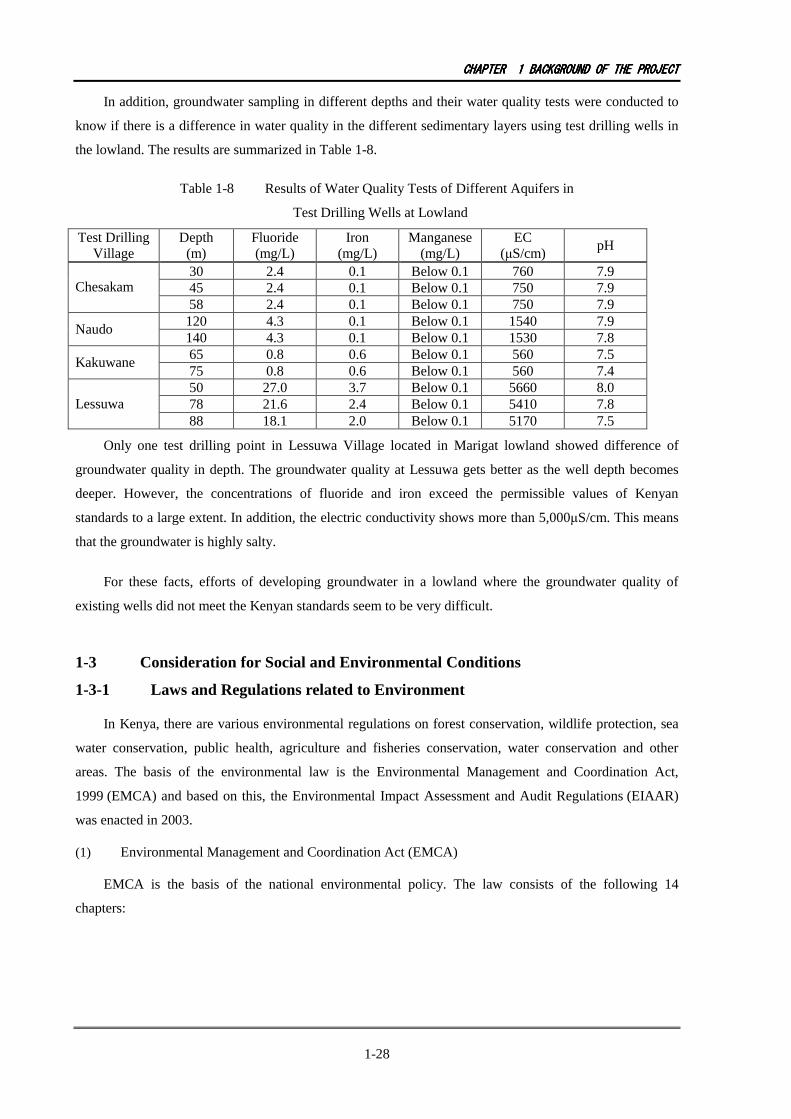
In addition, groundwater sampling in different depths and their water quality tests were conducted to
know if there is a difference in water quality in the different sedimentary layers using test drilling wells in
the lowland. The results are summarized in Table 1-8.
Table 1-8 Results of Water Quality Tests of Different Aquifers in
Test Drilling Wells at Lowland
Test Drilling Village
Depth (m)
Fluoride (mg/L)
Iron (mg/L)
Manganese (mg/L)
EC (µS/cm)
pH
30 2.4 0.1 Below 0.1 760 7.9 45 2.4 0.1 Below 0.1 750 7.9 Chesakam 58 2.4 0.1 Below 0.1 750 7.9 120 4.3 0.1 Below 0.1 1540 7.9
Naudo 140 4.3 0.1 Below 0.1 1530 7.8 65 0.8 0.6 Below 0.1 560 7.5
Kakuwane 75 0.8 0.6 Below 0.1 560 7.4 50 27.0 3.7 Below 0.1 5660 8.0 78 21.6 2.4 Below 0.1 5410 7.8 Lessuwa 88 18.1 2.0 Below 0.1 5170 7.5
Only one test drilling point in Lessuwa Village located in Marigat lowland showed difference of
groundwater quality in depth. The groundwater quality at Lessuwa gets better as the well depth becomes
deeper. However, the concentrations of fluoride and iron exceed the permissible values of Kenyan
standards to a large extent. In addition, the electric conductivity shows more than 5,000µS/cm. This means
that the groundwater is highly salty.
For these facts, efforts of developing groundwater in a lowland where the groundwater quality of
existing wells did not meet the Kenyan standards seem to be very difficult.
1-3 Consideration for Social and Environmental Conditions
1-3-1 Laws and Regulations related to Environment
In Kenya, there are various environmental regulations on forest conservation, wildlife protection, sea
water conservation, public health, agriculture and fisheries conservation, water conservation and other
areas. The basis of the environmental law is the Environmental Management and Coordination Act,
1999 (EMCA) and based on this, the Environmental Impact Assessment and Audit Regulations (EIAAR)
was enacted in 2003.
(1) Environmental Management and Coordination Act (EMCA)
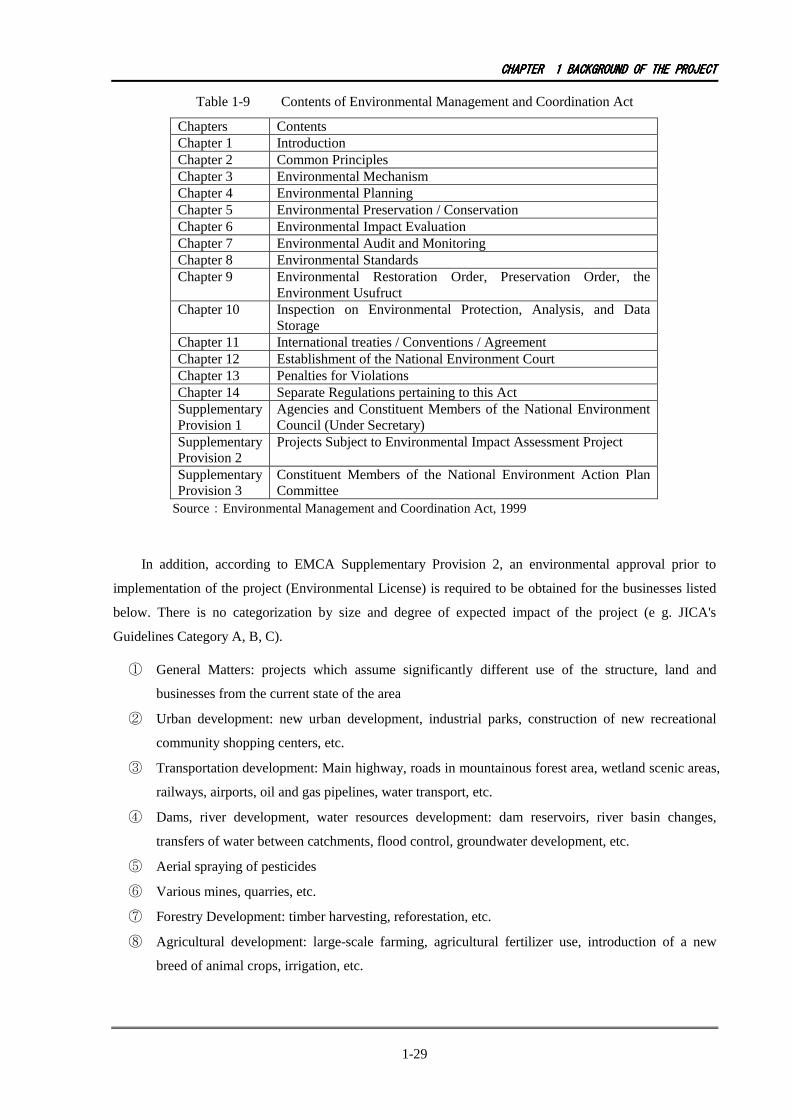
EMCA is the basis of the national environmental policy. The law consists of the following 14
chapters:
CHAPTERCHAPTERCHAPTERCHAPTER 1111 BACKGROUNDBACKGROUNDBACKGROUNDBACKGROUND OFOFOFOF THETHETHETHE PROJECTPROJECTPROJECTPROJECT
1-29
Table 1-9 Contents of Environmental Management and Coordination Act
Chapters Contents Chapter 1 Introduction Chapter 2 Common Principles Chapter 3 Environmental Mechanism Chapter 4 Environmental Planning Chapter 5 Environmental Preservation / Conservation Chapter 6 Environmental Impact Evaluation Chapter 7 Environmental Audit and Monitoring Chapter 8 Environmental Standards Chapter 9 Environmental Restoration Order, Preservation Order, the
Environment Usufruct Chapter 10 Inspection on Environmental Protection, Analysis, and Data
Storage Chapter 11 International treaties / Conventions / Agreement Chapter 12 Establishment of the National Environment Court Chapter 13 Penalties for Violations Chapter 14 Separate Regulations pertaining to this Act Supplementary Provision 1
Agencies and Constituent Members of the National Environment Council (Under Secretary)
Supplementary Provision 2
Projects Subject to Environmental Impact Assessment Project
Supplementary Provision 3
Constituent Members of the National Environment Action Plan Committee
Source:Environmental Management and Coordination Act, 1999
In addition, according to EMCA Supplementary Provision 2, an environmental approval prior to
implementation of the project (Environmental License) is required to be obtained for the businesses listed
below. There is no categorization by size and degree of expected impact of the project (e g. JICA's
Guidelines Category A, B, C).
① General Matters: projects which assume significantly different use of the structure, land and
businesses from the current state of the area
② Urban development: new urban development, industrial parks, construction of new recreational
community shopping centers, etc.
③ Transportation development: Main highway, roads in mountainous forest area, wetland scenic areas,
railways, airports, oil and gas pipelines, water transport, etc.
④ Dams, river development, water resources development: dam reservoirs, river basin changes,
transfers of water between catchments, flood control, groundwater development, etc.
⑤ Aerial spraying of pesticides
⑥ Various mines, quarries, etc.
⑦ Forestry Development: timber harvesting, reforestation, etc.
⑧ Agricultural development: large-scale farming, agricultural fertilizer use, introduction of a new
breed of animal crops, irrigation, etc.

CHAPTERCHAPTERCHAPTERCHAPTER 1111 BACKGROUNDBACKGROUNDBACKGROUNDBACKGROUND OFOFOFOF THETHETHETHE PROJECTPROJECTPROJECTPROJECT
1-30
⑨ Industrial Development: ore smelting, casting, brick, cement, fertilizers, petroleum refining,
chemical manufacturing, leather tanning, food processing, automobiles, machinery, other
manufacturing
⑩ Power Development:
⑪ Natural gas, flammable or explosive gas management
⑫ Sewage effluent various gas, waste disposal, etc.
⑬ Protecting the natural environment in the development of conservation areas: national parks,
hunting district, the development of Wildlife, forestry, catchment management, ecosystem
management, etc.
⑭ Nuclear energy development
⑮ Biotechnological development: the introduction of technologies such as genetically modified
organisms
⑯ Items related to this Project in the above listed 15 provisions are ④, ⑦ and ⑬.
(2) Environmental Impact Assessment and Audit Regulations (EIAAR)
With respect to environmental and social considerations based on the EMCA above, enacted was the
EIAAR defining the licensing procedures for EIA related to the principal’s role.
Table 1-10 Contents of Environmental Impact Assessment and
Audit Regulations (EIAAR))
Chapters Contents Chapter 1 Preface Chapter 2 Project Report Chapter 3 Full-scale EIA study report Chapter 4 Environmental Impact Assessment (EIA full-scale) Research Report Chapter 5 Environmental Audit and Monitoring Chapter 6 Bylaws
(Environment Impact Assessment, penalty)
Supplementary Provisions 1
Various forms of documents (application forms, certification, etc.)
Supplementary provisions 2
Parameters to be considered in Environmental Impact Assessment
Supplementary Provisions 3
EIA study report contents
Supplementary Provisions 4
EIA specialist certification standards
Supplementary Provisions 5
Costs relating to Environmental License
Source:Environmental (Impact Assessment and Audit) Regulations, 2003
In addition, the National Environmental Management Agency (NEMA) drafted the Environmental
Impact Assessment Guideline and Administrative Procedure in 2002 in line with the EIAAR. Also, as to

CHAPTERCHAPTERCHAPTERCHAPTER 1111 BACKGROUNDBACKGROUNDBACKGROUNDBACKGROUND OFOFOFOF THETHETHETHE PROJECTPROJECTPROJECTPROJECT
1-31
the water sector, the EIA manual and guidelines have been produced in Part D of the “DMWS” and the
procedures are conducted in accordance with these regulations.
1-3-2 Environmental Licensing Procedure and Duration
Environmental license has the following 2 steps based on the EIAAR.
(1) Step -1:Projects licensed with a simple project report
(a) Procedure: After submission of project reports, NEMA conducts an appraisal and if there is little or negligible environmental impact, an environmental permit (Environmental License) is issued.
(b) Examination period:Generally, within 45 days after a project report is submitted (including weekends and bank holidays)
(c) Others: After the target communities are selected project reports need to be expeditiously submitted. ‘Licensed’ or ‘implementation of a full scale EIA’ is decided upon appraisal.
(2) Step -2:Projects that require a full-EIA study and EIA report
(a) Procedure: NEMA reviews the project report, and if significant or some effects are expected, a full scale EIA is requested. After a full EIA report is submitted, an appraisal is conducted.
(b) Examination period:Generally, within 3 months after a project report is submitted to NEMA (including weekends and bank holidays)
(c) Others: these steps include clarification of social and environmental parameters through screening, approval of environmental selected specialists after a public hearing and EIA and submission of the report. In case the projected received ‘not licensed’, the project needs to be re-planned
The following items are to be included in a project report.
(1) Name, PIN number, address, person in charge, telephone, fax and mailing address
(2) Title of the project
(3) Purpose and magnitude of the Project
(4) Contents of the Project
(5) Target Area
(6) Development environment parameters at the time of construction and servicing:
(a) Design of the project
(b) Materials used during construction, an overview of products and byproducts, and the method of disposal
(c) Preventive measures to reduce problems at and after the project implementation
(d) Accident prevention that could occur with the project and management action plan
(e) Health and Safety Management Plan for the workers and residents in the vicinity
(f) Economic impact on national and local communities levels
(g) Project Cost
(h) Public nature of the project
(j) Environmental Management Plan for the entire project
CHAPTERCHAPTERCHAPTERCHAPTER 1111 BACKGROUNDBACKGROUNDBACKGROUNDBACKGROUND OFOFOFOF THETHETHETHE PROJECTPROJECTPROJECTPROJECT
1-32
In addition, the matters described in the EIA shall include the following items:
(1) Target Area
(2) Various business-related laws and regulations, and other information about the underlying data
(3) Purpose of the project
(4) Technology and processes that apply to the implementation of the project
(5) Materials to be used when implementing a project
(6) Products produced with the project, by-products and wastes
(7) The expected impact of the environment
(8) Environmental impact expected from the project implementation (social and cultural influence, direct or indirect effects, the accumulation effect, and long-term and short-term impact)
(9) Possible alternatives (technologies, processes, etc.) and their reasons for selection
(10) Avoidance the environmental impact of the project, the costs of environmental management, duration, responsibilities, etc.
(11) Prevention of accidents through the expected time in service during construction and presentation of Action Plan for the dangerous task management, etc.
(12) Emergency measures for management of health and safety of workers and employees
(13) Lack of information about the environment and recognition of the predicted gap
(14) Economic analysis of the project
(15) Environmental impact in other cases and mitigation measures to ensure a possible workaround
(16) In addition to the above, other parameters and issues requested by NEMA
It was confirmed that environmental licensing is conducted by the Government of Kenya. Basically, a
project report is sufficient as long as the project stays off the protected area. The target communities are
categorized by location and natural environment and reports are prepared following these categories. The
project report is finalized after the selection of the target communities. RV-WSB hires consultants officially
registered in NEMA to conduct the assessment.
CHAPTERCHAPTERCHAPTERCHAPTER 2222 CONTENTSCONTENTSCONTENTSCONTENTS OFOFOFOF THETHETHETHE PROJECTPROJECTPROJECTPROJECT
2-1
CHAPTER 2 CONTENTS OF THE PROJECT
2-1 Basic Concepts of the Project
The plan governing the rural water supply projects is “Vision 2030”, the long term national
development strategy of the Kenya until 2030, and the goal of water coverage proportion is set at 70% in
rural areas.
The National Water Services Strategy for 2007-2015, which follows the Water Act of 2002, elaborates
the new strategy in the water sector, aiming at water coverage of the national average of 80% in urban and
59% in rural area, which was 57% in 2005/2006 (60% in urban area, 40% in rural area). Access to safe
water with a public tap is to be less than 2km. The project is guided by these superior plan and strategy, and
is positioned to contribute to improve the rural water supply.
The safe water coverage rate, such as piped water and groundwater, is estimated at about 24% in the
survey area, Baringo area, including Baring Central, North Baringo, Marigat and East Pokot districts.
Majority of the people need to use dug wells on riverbed, reservoir and springs without sanitation.
Therefore, it is an urgent challenge to secure safe and stable water sources.
The project targets 90 sites in Baringo County, and to construct water supply facilities independently
in order to increase the water supply coverage rate from 24 % to 37%, with which an improvement of
living conditions of the target area is aimed.
To achieve the above objective, the Project is to construct water supply facilities in the target sites.
Higher priority is given to communities which have many problems to supply safe and stabile water.
Further, the Project is to procure equipment for operation and maintenance of the water supply facilities.
Assistance to the management of operation and maintenance is to be provided, such as the training of
extension officers in the District Water Office and water users association of the communities, to support
establishment of water users association, to train people related to the Project. A summary of the
cooperation is outlined in Table 2-1.
Table 2-1 Scope of the Project
Items Contents Outline Facility Construction
Construction of Water Supply Facility
90 sites (borehole, pumping facility, storage tank, public tap, distribution pipe, trough for domestic animal)
Procurement of Equipment
Procurement of Equipment for operation and maintenance
1 double cabin pick-up (4WD), 2 motorbikes(175cc), 1 desktop computer, 1 printer
Assistance to Operation and Maintenance
Organizational capacity building training
• Training of extension workers in the District Water Office
• Establish Water Users Association, Training of the members of WUA

CHAPTERCHAPTERCHAPTERCHAPTER 2222 CONCONCONCONTENTSTENTSTENTSTENTS OFOFOFOF THETHETHETHE PROJECTPROJECTPROJECTPROJECT
2-2
2-2 Outline Design of the Japanese Assistance
2-2-1 Design Policy
2-2-1-1 Basic Policy
(1) Scope of Cooperation
Based on the review of the request from the Kenyan side, the Project shall construct water supply
facilities with boreholes, pumping equipment, storage tank, transmission pipes in sites selected from
190 communities in Baringo with high priority, including Baringo Central, North Baringo, Marigat and
East Pokot districts.
Equipment for operation and maintenance is to be procured to strengthen technical capacity in the
District Water Office. Assistance to management and guidance is planned for sustainable operation and
maintenance in order to establish water users association, and training for members of WUA.
(2) Selection of Target Communities
Target communities are to be selected on the priority basis considering conditions of the existing
water supply facilities, access to the target area, groundwater development potential, and operation and
maintenance capacity of the communities.
Groundwater potential is to be evaluated by the characteristics of each zone categorized by geological
and topographical conditions based on the analysis of geophysical prospecting survey, test drilling and
hydro-geological data. Borehole conditions with depth, water level and success rate is to be estimated in all
sites. Water quality is to be assessed of fluoride, saline and temperatures (vapour).
Operation and maintenance capacity is to be assessed with the results of social survey in order to
evaluate community’s capacity to operate and maintain a facility.
Based on above-mentioned evaluation, communities having difficulties to operate a facility
sustainably are excluded. After priorities are given, types of pumping facility and other facilities are
planned. Success rate of the borehole construction is to be estimated. Accordingly, the necessary number of
reserved sites are to be selected.
(3) Fluoride Treatment
Fluoride concentration at lowland is expected to be beyond 3.0 mg/L of the Kenya standards. Fluoride
treatment by bone-char has been introduced by an NGO in the target area, and this method may be
technically acceptable. However, bone-char materials have to be replaced periodically. Some communities
made replacement with the assistance of an NGO. In the case of fluoride, hazardous effect to human health
is serious in case the concentration is high; however, it is difficult to check by colour and taste of elements
such as iron and manganese.
CHAPTERCHAPTERCHAPTERCHAPTER 2222 CONTENTSCONTENTSCONTENTSCONTENTS OFOFOFOF THETHETHETHE PROJECTPROJECTPROJECTPROJECT
2-3
Therefore, fluoride treatment is not included in the Project because the scheme of a Grant Aid Project
does not follow a longer term support which is required for the treatment. If the water quality of borehole
exceeds the standards of Kenya, borehole is sealed at the top of casing and transferred to Kenya with the
condition that the water is not suitable for drinking.
(4) Target Communities and Water Supply Facility Level
The Project aims to secure safe and stable borehole water source with pumping facility, elevated water
storage tank, water vending kiosk and a maintenance room.
A suitable power supply for pumping is to be selected according to the site condition. Electric power
from the commercial grid, solar panel and generator are the options. Additionally, the following conditions
are considered. If position of the borehole is selected at the hollow site far from the road on ridge, storage
tank and kiosk house is to be constructed near the road for the benefit of people, and water is to be
transmitted from borehole to the tank.
(5) Water Supply Facility
(a) Method of Facility Planning
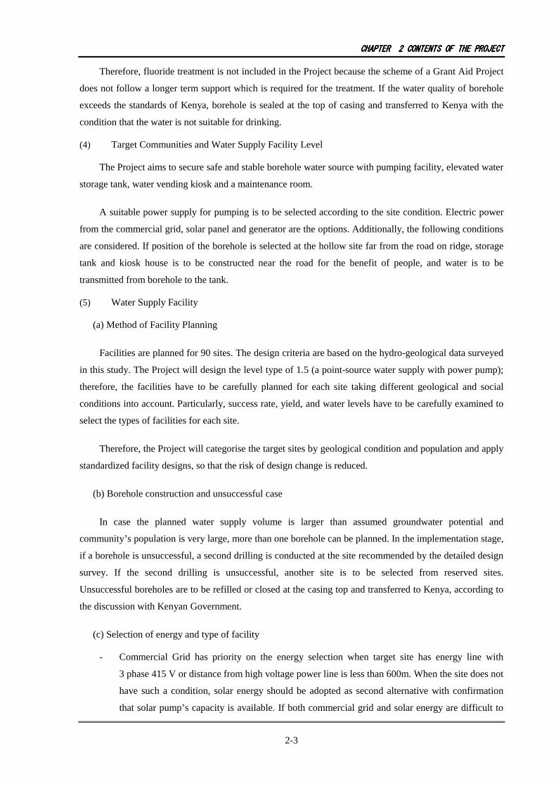
Facilities are planned for 90 sites. The design criteria are based on the hydro-geological data surveyed
in this study. The Project will design the level type of 1.5 (a point-source water supply with power pump);
therefore, the facilities have to be carefully planned for each site taking different geological and social
conditions into account. Particularly, success rate, yield, and water levels have to be carefully examined to
select the types of facilities for each site.
Therefore, the Project will categorise the target sites by geological condition and population and apply
standardized facility designs, so that the risk of design change is reduced.
(b) Borehole construction and unsuccessful case
In case the planned water supply volume is larger than assumed groundwater potential and
community’s population is very large, more than one borehole can be planned. In the implementation stage,
if a borehole is unsuccessful, a second drilling is conducted at the site recommended by the detailed design
survey. If the second drilling is unsuccessful, another site is to be selected from reserved sites.
Unsuccessful boreholes are to be refilled or closed at the casing top and transferred to Kenya, according to
the discussion with Kenyan Government.
(c) Selection of energy and type of facility
- Commercial Grid has priority on the energy selection when target site has energy line with
3 phase 415 V or distance from high voltage power line is less than 600m. When the site does not
have such a condition, solar energy should be adopted as second alternative with confirmation
that solar pump’s capacity is available. If both commercial grid and solar energy are difficult to
CHAPTERCHAPTERCHAPTERCHAPTER 2222 CONTENTSCONTENTSCONTENTSCONTENTS OFOFOFOF THETHETHETHE PROJECTPROJECTPROJECTPROJECT
2-4
select, a generator can be applied when the community has capacity to pay its cost of operation
and maintenance.
- Other water supply facilities are composed of a borehole pit, transmission pipes, a storage tank, a
water kiosk, an animal water trough and protection fence. These facilities should be considered
as to their endurance, function and cost performance.
- When the volume of borehole pit is the same as the transmit pipe, one design is applied if the
transmission pipes have no significant difference.
- Material and installation method of the transmission pipe should be determined in consideration
of condition of surface soil. Size of the pipe can be same, and length of pipe shall adopt the
average of the estimated length of the target communities.
- Storage tank is the elevated type. However, tanks on the ground are used if a naturally elevated
position is available.
- Water kiosk is designed with endurance. When generator is required, separate room for the
generator is to be installed.
- The Contractor shall construct fences and drains.
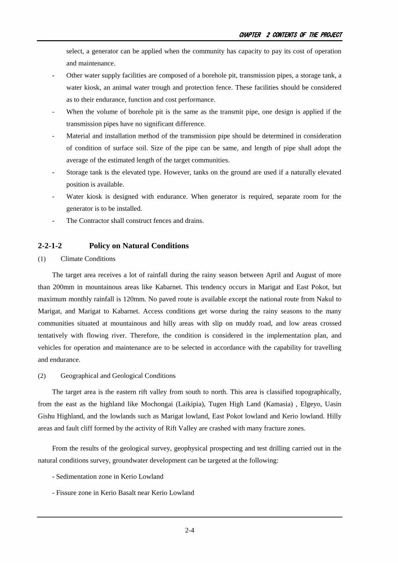
2-2-1-2 Policy on Natural Conditions
(1) Climate Conditions
The target area receives a lot of rainfall during the rainy season between April and August of more
than 200mm in mountainous areas like Kabarnet. This tendency occurs in Marigat and East Pokot, but
maximum monthly rainfall is 120mm. No paved route is available except the national route from Nakul to
Marigat, and Marigat to Kabarnet. Access conditions get worse during the rainy seasons to the many
communities situated at mountainous and hilly areas with slip on muddy road, and low areas crossed
tentatively with flowing river. Therefore, the condition is considered in the implementation plan, and
vehicles for operation and maintenance are to be selected in accordance with the capability for travelling
and endurance.
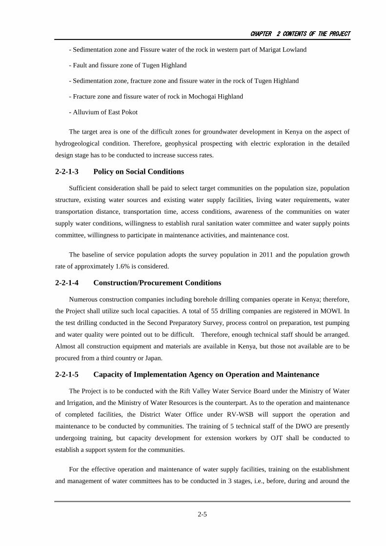
(2) Geographical and Geological Conditions
The target area is the eastern rift valley from south to north. This area is classified topographically,
from the east as the highland like Mochongai (Laikipia), Tugen High Land (Kamasia) , Elgeyo, Uasin
Gishu Highland, and the lowlands such as Marigat lowland, East Pokot lowland and Kerio lowland. Hilly
areas and fault cliff formed by the activity of Rift Valley are crashed with many fracture zones.
From the results of the geological survey, geophysical prospecting and test drilling carried out in the
natural conditions survey, groundwater development can be targeted at the following:
- Sedimentation zone in Kerio Lowland
- Fissure zone in Kerio Basalt near Kerio Lowland
CHAPTERCHAPTERCHAPTERCHAPTER 2222 CONTENTSCONTENTSCONTENTSCONTENTS OFOFOFOF THETHETHETHE PROJECTPROJECTPROJECTPROJECT
2-5
- Sedimentation zone and Fissure water of the rock in western part of Marigat Lowland
- Fault and fissure zone of Tugen Highland
- Sedimentation zone, fracture zone and fissure water in the rock of Tugen Highland
- Fracture zone and fissure water of rock in Mochogai Highland
- Alluvium of East Pokot
The target area is one of the difficult zones for groundwater development in Kenya on the aspect of
hydrogeological condition. Therefore, geophysical prospecting with electric exploration in the detailed
design stage has to be conducted to increase success rates.
2-2-1-3 Policy on Social Conditions
Sufficient consideration shall be paid to select target communities on the population size, population
structure, existing water sources and existing water supply facilities, living water requirements, water
transportation distance, transportation time, access conditions, awareness of the communities on water
supply water conditions, willingness to establish rural sanitation water committee and water supply points
committee, willingness to participate in maintenance activities, and maintenance cost.
The baseline of service population adopts the survey population in 2011 and the population growth
rate of approximately 1.6% is considered.
2-2-1-4 Construction/Procurement Conditions
Numerous construction companies including borehole drilling companies operate in Kenya; therefore,
the Project shall utilize such local capacities. A total of 55 drilling companies are registered in MOWI. In
the test drilling conducted in the Second Preparatory Survey, process control on preparation, test pumping
and water quality were pointed out to be difficult. Therefore, enough technical staff should be arranged.
Almost all construction equipment and materials are available in Kenya, but those not available are to be
procured from a third country or Japan.
2-2-1-5 Capacity of Implementation Agency on Operation and Maintenance
The Project is to be conducted with the Rift Valley Water Service Board under the Ministry of Water
and Irrigation, and the Ministry of Water Resources is the counterpart. As to the operation and maintenance
of completed facilities, the District Water Office under RV-WSB will support the operation and
maintenance to be conducted by communities. The training of 5 technical staff of the DWO are presently
undergoing training, but capacity development for extension workers by OJT shall be conducted to
establish a support system for the communities.
For the effective operation and maintenance of water supply facilities, training on the establishment
and management of water committees has to be conducted in 3 stages, i.e., before, during and around the
CHAPTERCHAPTERCHAPTERCHAPTER 2222 CONTENTSCONTENTSCONTENTSCONTENTS OFOFOFOF THETHETHETHE PROJECTPROJECTPROJECTPROJECT
2-6
completion of construction works. Further training on operation, maintenance and repair of facilities have
to be conducted for the water users association/s during the construction work.
2-2-1-6 Facilities and Equipment Grade Setting
Water supply facilities that require minimum costs are designed. As community facilities, they are
designed for easy operation and maintenance with high durability to enable sustainable use. The target area
lags behind in infrastructure development, and even main trunk roads are unpaved. A 4x4 pick-up truck is
to be procured because road conditions are very poor especially during the rainy seasons.
2-2-1-7 Construction Method/Procurement and Construction Period
The Project shall adopt a construction method that the local companies can work with, considering the
deployment of local construction companies. Construction materials that can be procured at the site or from
neighbouring countries shall be selected to lower the cost.
Concrete apron and wastewater drainage facilities are to be primarily installed when the boreholes are
drilled. The order of construction shall take priority according to the community’s urgent requirement, but
efficiency of the work plan shall be given the highest consideration.
2-2-2 Basic Plan (Construction Plan/Equipment Plan)
2-2-2-1 Basic Design
(1) Target Year of the Project
The target year of the Project is set at 2015. The target population adds a population growth rate
(about 1.6%) to the result of the population survey in 2011 as the baseline. The service population was
estimated from the Social Survey and the interviews.
(2) Service area and Service Population
The National Water Service Strategy aims to make the distance from home to a water source within
2km in rural areas. Existing water sources are river water, dug well at riverbeds and spring water. People
fetch water from the water sources at 0.2 to 1km in the rainy season. The distance varies in the dry season
in East Pokot and Marigat which is up to 5 km. The distribution of houses in the target area was assessed
through a satellite photo image. Most houses are located within 2 to 3km, around 2km on average from a
water source. Service population of the Project is estimated basically from the results of the social survey.
Water demands of day schools and bordering schools are also included in the Project.
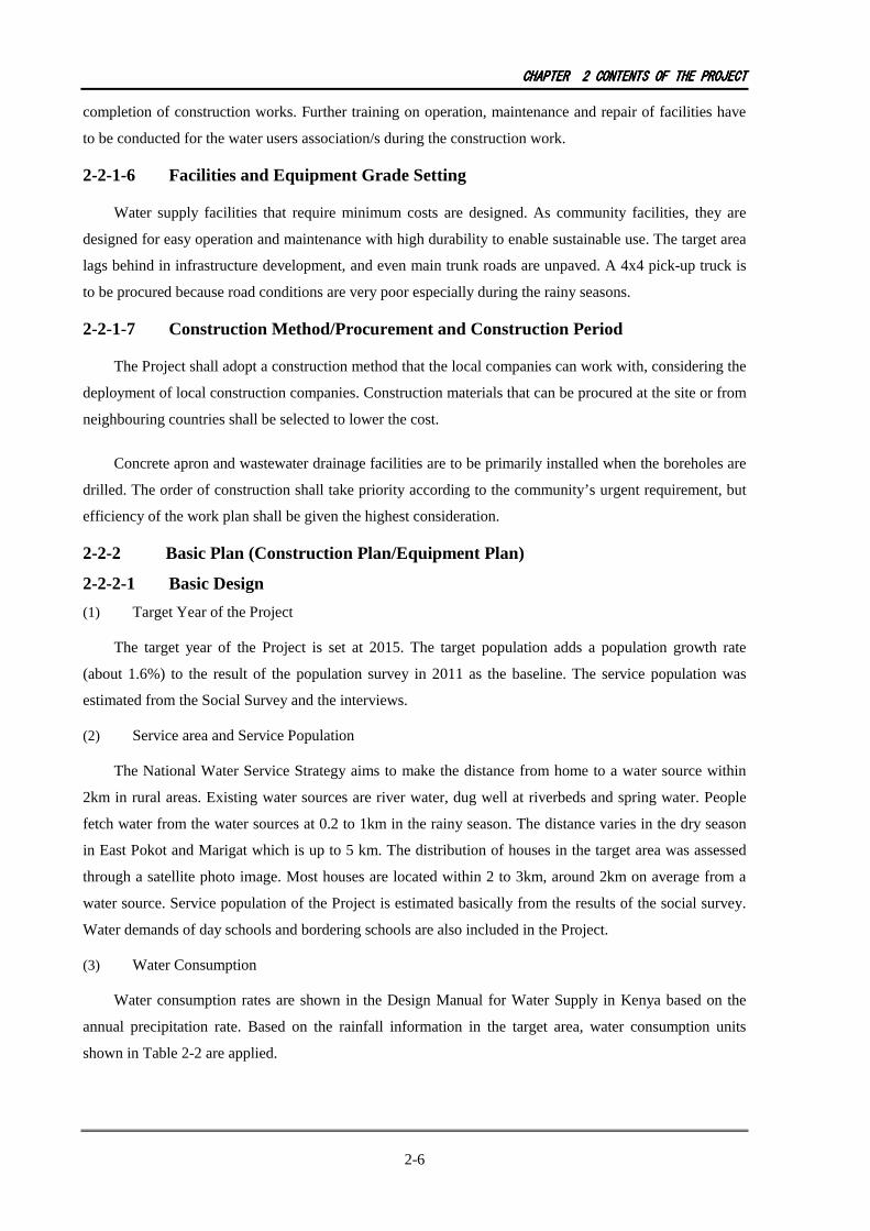
(3) Water Consumption
Water consumption rates are shown in the Design Manual for Water Supply in Kenya based on the
annual precipitation rate. Based on the rainfall information in the target area, water consumption units
shown in Table 2-2 are applied.
CHAPTERCHAPTERCHAPTERCHAPTER 2222 CONTENTSCONTENTSCONTENTSCONTENTS OFOFOFOF THETHETHETHE PROJECTPROJECTPROJECTPROJECT
2-7
Table 2-2 Water Supply Unit
Average Precipitation/Year Water Supply Unit Area
1000 mm and above 20 L/person/day Kabarnet North Kabarnet
500 mm and above, below 1000mm 15 L/person/day East Pokot Marigat
Below 500 mm 10 L/person/day -
According to the Manual, consumption is 5 L/p/d for day schools, and 50 L/p/d for boarding schools.
However, for the Project the value shown in Table 2-3 is applied considering the level 1.5 (point water
source) system and the difficulty of groundwater development in the area.
Table 2-3 Water Supply Unit at School
School Facility Standard Project Day School 5 L/person/day 2 L/person/day
Boarding School 50 L/person/day 15/20 L/person/day (depending on district)
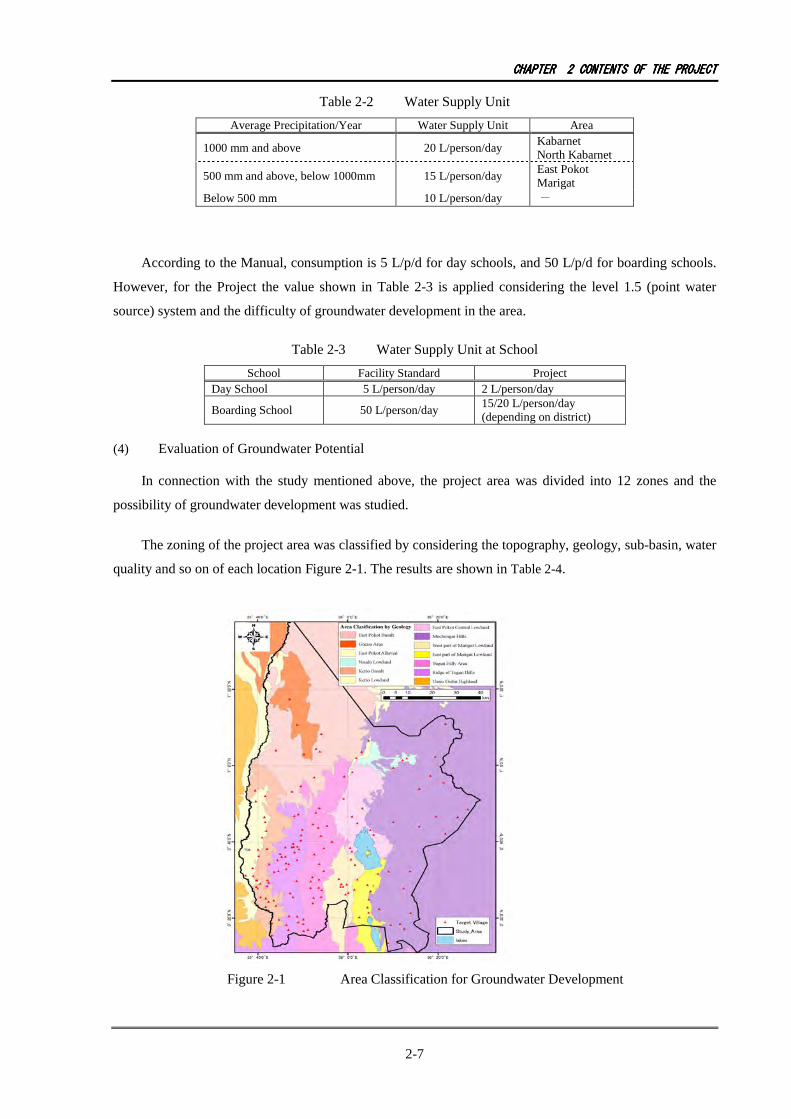
(4) Evaluation of Groundwater Potential
In connection with the study mentioned above, the project area was divided into 12 zones and the
possibility of groundwater development was studied.
The zoning of the project area was classified by considering the topography, geology, sub-basin, water
quality and so on of each location Figure 2-1. The results are shown in Table 2-4.
Figure 2-1 Area Classification for Groundwater Development
CHAPTERCHAPTERCHAPTERCHAPTER 2222 CONTENTSCONTENTSCONTENTSCONTENTS OFOFOFOF THETHETHETHE PROJECTPROJECTPROJECTPROJECT
2-8
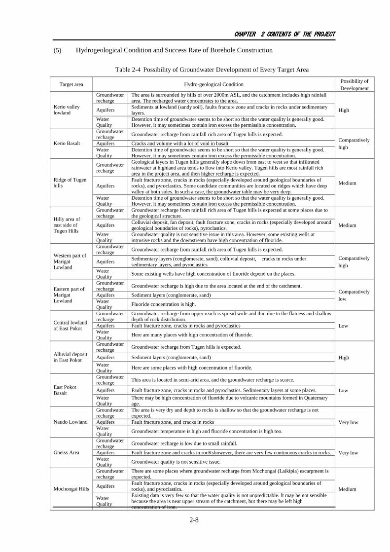
(5) Hydrogeological Condition and Success Rate of Borehole Construction
Table 2-4 Possibility of Groundwater Development of Every Target Area
Target area Hydro-geological Condition Possibility of Development
Groundwater recharge
The area is surrounded by hills of over 2000m ASL, and the catchment includes high rainfall area. The recharged water concentrates to the area.
Aquifers Sediments at lowland (sandy soil), faults fracture zone and cracks in rocks under sedimentary layers.
Kerio valley lowland
Water Quality
Detention time of groundwater seems to be short so that the water quality is generally good. However, it may sometimes contain iron excess the permissible concentration.
High
Groundwater recharge Groundwater recharge from rainfall rich area of Tugen hills is expected.
Aquifers Cracks and volume with a lot of void in basalt Kerio Basalt Water Quality
Detention time of groundwater seems to be short so that the water quality is generally good. However, it may sometimes contain iron excess the permissible concentration.
Comparatively high
Groundwater recharge
Geological layers in Tugen hills generally slope down from east to west so that infiltrated rainwater at highland area tends to flow into Kerio valley. Tugen hills are most rainfall rich area in the project area, and then higher recharge is expected.
Aquifers Fault fracture zone, cracks in rocks (especially developed around geological boundaries of rocks), and pyroclastics. Some candidate communities are located on ridges which have deep valley at both sides. In such a case, the groundwater table may be very deep.
Ridge of Tugen hills
Water Quality
Detention time of groundwater seems to be short so that the water quality is generally good. However, it may sometimes contain iron excess the permissible concentration.
Medium
Groundwater recharge
Groundwater recharge from rainfall rich area of Tugen hills is expected at some places due to the geological structure.
Aquifers Colluvial deposit, fan deposit, fault fracture zone, cracks in rocks (especially developed around geological boundaries of rocks), pyroclastics.
Hilly area of east side of Tugen Hills
Water Quality
Groundwater quality is not sensitive issue in this area. However, some existing wells at intrusive rocks and the downstream have high concentration of fluoride.
Medium
Groundwater recharge Groundwater recharge from rainfall rich area of Tugen hills is expected.
Aquifers Sedimentary layers (conglomerate, sand), colluvial deposit, cracks in rocks under sedimentary layers, and pyroclastics
Western part of Marigat Lowland
Water Quality
Some existing wells have high concentration of fluoride depend on the places.
Comparatively high
Groundwater recharge
Groundwater recharge is high due to the area located at the end of the catchment.
Aquifers Sediment layers (conglomerate, sand) Eastern part of Marigat Lowland Water
Quality Fluoride concentration is high.
Comparatively low
Groundwater recharge
Groundwater recharge from upper reach is spread wide and thin due to the flatness and shallow depth of rock distribution.
Aquifers Fault fracture zone, cracks in rocks and pyroclastics Central lowland of East Pokot
Water Quality
Here are many places with high concentration of fluoride.
Low
Groundwater recharge
Groundwater recharge from Tugen hills is expected.
Aquifers Sediment layers (conglomerate, sand) Alluvial deposit in East Pokot
Water Quality
Here are some places with high concentration of fluoride.
High
Groundwater recharge
This area is located in semi-arid area, and the groundwater recharge is scarce.
Aquifers Fault fracture zone, cracks in rocks and pyroclastics. Sedimentary layers at some places. East Pokot Basalt
Water Quality
There may be high concentration of fluoride due to volcanic mountains formed in Quaternary age.
Low
Groundwater recharge
The area is very dry and depth to rocks is shallow so that the groundwater recharge is not expected.
Aquifers Fault fracture zone, and cracks in rocks Naudo Lowland Water Quality
Groundwater temperature is high and fluoride concentration is high too.
Very low
Groundwater recharge
Groundwater recharge is low due to small rainfall.
Aquifers Fault fracture zone and cracks in rocKshowever, there are very few continuous cracks in rocks. Gneiss Area Water Quality
Groundwater quality is not sensitive issue.
Very low
Groundwater recharge
There are some places where groundwater recharge from Mochongai (Laikipia) escarpment is expected.
Aquifers Fault fracture zone, cracks in rocks (especially developed around geological boundaries of rocks), and pyroclastics. Mochongai Hills
Water Quality
Existing data is very few so that the water quality is not unpredictable. It may be not sensible because the area is near upper stream of the catchment, but there may be left high concentration of iron.
Medium

CHAPTERCHAPTERCHAPTERCHAPTER 2222 CONTENTSCONTENTSCONTENTSCONTENTS OFOFOFOF THETHETHETHE PROJECTPROJECTPROJECTPROJECT
2-9
A database was compiled using the data collected for the existing boreholes. The data are
categorized by geographical conditions. The drilling depths, yields, and static water levels are
statistically summarized. The data with drilling depth were 194, those with yield were 170 and those
with static water level were 96. As to water quality, the number of data gets scarce that TDS was
recorded with 52, fluoride with 56 and iron with 55 data sets. Other relevant information was “in use
or abandoned.” The data sets were analysed by area. Table 2-5 shows the summary of average and
distribution range of each parameter for existing boreholes. This table includes the data collected
during the preparatory survey for the Project.
CHAPTERCHAPTERCHAPTERCHAPTER 2222 CONTENTSCONTENTSCONTENTSCONTENTS OFOFOFOF THETHETHETHE PROJECTPROJECTPROJECTPROJECT
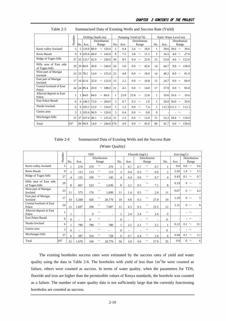
2-10
Table 2-5 Summarized Data of Existing Wells and Success Rate (Yield)
Drilling Depth (m) Pumping Yield (m3/h) Static Water Level (m)
Nu
mb
er
No. Ave. Distribution
Range No. Ave. Distribution
Range No Ave. Distribution
Range
Kerio valley lowland 5 5 110.0 80.0 ~ 150.0 5 9.4 3.6 ~ 18.0 1 39.6 39.6 ~ 39.6
Kerio Basalt 9 9 105.6 40.0 ~ 143.0 8 7.5 3.8 ~ 11.1 5 16.5 4.0 ~ 27.0
Ridge of Tugen hills 37 35 133.7 42.0 ~ 230.0 30 8.5 0.4 ~ 22.0 15 53.0 4.6 ~ 122.0
Hilly area of East side of Tugen hills
29 29 84.9 30.0 ~ 244.0 26 5.0 0.0 ~ 45.0 14 44.7 9.8 ~ 156.0
West part of Marigat lowland
23 23 78.1 14.0 ~ 155.0 22 4.8 0.0 ~ 18.0 14 40.2 8.9 ~ 81.9
East part of Marigat lowland 17 16 61.6 25.0 ~ 122.0 15 2.2 0.0 ~ 10.8 12 24.7 0.0 ~ 60.9
Central lowland of East Pokot
24 24 89.4 20.0 ~ 188.0 21 4.5 0.0 ~ 14.8 17 37.9 0.0 ~ 85.8
Alluvial deposit in East Pokot 1 1 84.0 84.0 ~ 84.0 1 23.8 23.8 ~ 23.8 1 10.6 10.6 ~ 10.6
East Pokot Basalt 6 6 140.5 75.0 ~ 204.0 3 0.7 0.3 ~ 1.0 1 50.0 50.0 ~ 50.0
Naudo lowland 6 6 103.2 22.0 ~ 154.0 5 1.5 0.0 ~ 7.4 1 112.3 112.3 ~ 112.3
Gneiss area 3 3 103.6 90.9 ~ 120.0 3 0.4 0.0 ~ 0.8 0 - - ~ -
Mochongoi hills 37 37 107.0 40.1 ~ 225.0 31 2.3 0.0 ~ 12.0 15 52.2 18.6 ~ 110.0
Total 197 194 99.9 14.0 ~ 244.0 170 4.9 0.0 ~ 45.0 96 41.7 0.0 ~ 156.0
Table 2-6 Summarized Data of Existing Wells and the Success Rate
(Water Quality)
TDS Fluoride (mg/L) Iron (mg/L)
Nu
mb
er
No. Ave. Distribution
Range No. Ave. Distribution
Range No. Ave. Distribution
Range
Kerio valley lowland 5 1 270 270 ~ 270 1 0.7 0.7 ~ 0.7 1 0.6 0.6 ~ 0.6
Kerio Basalt 9 2 113 113 ~ 113 2 0.4 0.3 ~ 0.6 2 2.45 1.4 ~ 3.5
Ridge of Tugen hills 37 4 125 100 ~ 145 4 0.4 0.0 ~ 0.7 4 0.43 0.1 ~ 0.7
Hilly area of East side of Tugen hills
29 8 667 523
~ 1,036 8 2.1 0.5
~ 7.1 8
0.19 0 ~ 1
West part of Marigat lowland
23 11 573 176
~ 1,699 11 1.4 0.5
~ 2.4 11
0.67 0 ~ 4.2
East part of Marigat lowland 17
10 5,568 426 ~
20,770 10 9.8 0.3 ~
27.0 10 1.29 0 ~ 5
Central lowland of East Pokot
24 12 1,697 200
~ 7,087 12 6.3 0.3
~ 22.5 12
1.21 0 ~ 6
Alluvial deposit in East Pokot
1 1 - 0
~ - 1 2.4 2.4
~ 2.4 0
- - ~ -
East Pokot Basalt 6 0 - 0 ~ - 0 - - ~ - 0 - - ~ -
Naudo lowland 6 1 780 780 ~ 780 1 2.1 2.1 ~ 2.1 1 0.12 0.1 ~ 0.1
Gneiss area 3 0 - - ~ - 0 - - ~ - 0 - - ~ -
Mochongoi hills 37 6 587 354 ~ 728 6 0.7 0.4 ~ 1.0 6 0.94 0.1 ~ 3.1
Total 197 52 1,676 100 ~ 20,770 56 3.9 0.0 ~ 27.9 55 0.9 0 ~ 6
The existing boreholes success rates were estimated by the success rates of yield and water
quality using the data in Table 2-6. The boreholes with yield of less than 1m3/hr were counted as
failure, others were counted as success. In terms of water quality, when the parameters for TDS,
fluoride and iron are higher than the permissible values of Kenya standards, the borehole was counted
as a failure. The number of water quality data is not sufficiently large that the currently functioning
boreholes are counted as success.

CHAPTERCHAPTERCHAPTERCHAPTER 2222 CONTENTSCONTENTSCONTENTSCONTENTS OFOFOFOF THETHETHETHE PROJECTPROJECTPROJECTPROJECT
2-11
Table 2-7 Success Rate of Existing Boreholes by Area
Water Volume Success Rate Water Quality Success Rate Zone Drilling
numbers Drilling numbers
Success Success
Rate Drilling numbers
Success Success Rate
Total Success
Rate
Kerio valley lowland 5 5 5 100.0 5 5 100.0 100.0
Kerio Basalt 9 8 8 100.0 2 0 0.0 0.0
Ridge of Tugen hills 37 37 29 78.4 33 26 78.8 61.8 Hilly area of East side of Tugen hills
29 29 18 62.1 20 18 90.0 55.9
West part of Marigat lowland 23 23 21 91.3 20 12 60.0 54.8
East part of Marigat lowland 17 16 10 62.5 10 1 10.0 6.3
Central lowland of East Pokot 24 24 16 66.7 19 6 31.6 21.1
Alluvial deposit in East Pokot 1 1 1 100.0 1 1 100.0 100.0
East Pokot Basalt 6 6 0 0.0 - - - 0.0
Naudo lowland 6 6 1 16.7 1 1 100.0 16.7
Gneiss area 3 3 0 0.0 3 3 100.0 0.0
Mochongoi hills 37 36 16 44.4 24 19 79.2 35.2
Total 197 194 125 64.4 138 92 66.7 43.0
The drilling depth, estimated yields, static water levels and success rates for the construction
works were estimated by geophysical conditions, the data analysis of GIS, electric exploration and
test drilling. As a result, the drilling depths are 100m, 150m, 200m, 250m with the static water levels
of 10 to 110m. The success rates were evaluated both from the water volume and quality. Therefore,
for all 118 sites of the target and reserve sites, the success rates were calculated. The average success
rate of these 118 sites is 56%.
Table 2-8 Success Rate of Project Sites by Depth
Drilling Depth (m) Qt’y Volume
Success Rate (%)
Water Quality Success Rate
(%)
Success Rate (%)
250 6 6 0 0.0
200 6 6 1 16.7
150 3 3 0 0.0
100 37 36 16 44.4
Total 118 72 79 56
(6) Selection of Target and Reserved Community
The preparatory survey narrowed down and prioritized the planned target communities for the
Project from necessity and construction possibility in the requested list of 190 communities.
As the first step, the 190 communities were narrowed down to 150 communities, and target
communities and reserved sites were selected in the second step.
Step 1: The communities with the following three conditions were excluded in the selection of 150
from 190 sites through discussion with DWO.
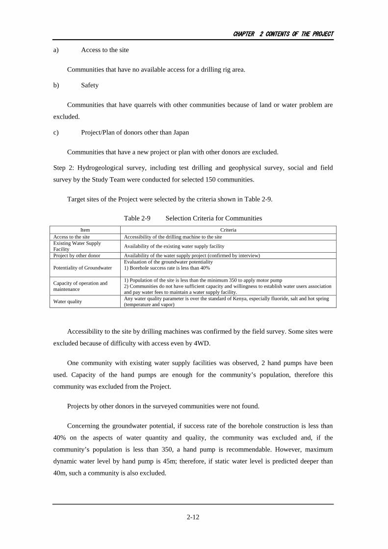
CHAPTERCHAPTERCHAPTERCHAPTER 2222 CONTENTSCONTENTSCONTENTSCONTENTS OFOFOFOF THETHETHETHE PROJECTPROJECTPROJECTPROJECT
2-12
a) Access to the site
Communities that have no available access for a drilling rig area.
b) Safety
Communities that have quarrels with other communities because of land or water problem are
excluded.
c) Project/Plan of donors other than Japan
Communities that have a new project or plan with other donors are excluded.
Step 2: Hydrogeological survey, including test drilling and geophysical survey, social and field
survey by the Study Team were conducted for selected 150 communities.
Target sites of the Project were selected by the criteria shown in Table 2-9.
Table 2-9 Selection Criteria for Communities
Item Criteria Access to the site Accessibility of the drilling machine to the site Existing Water Supply Facility
Availability of the existing water supply facility
Project by other donor Availability of the water supply project (confirmed by interview)
Potentiality of Groundwater Evaluation of the groundwater potentiality 1) Borehole success rate is less than 40%
Capacity of operation and maintenance
1) Population of the site is less than the minimum 350 to apply motor pump 2) Communities do not have sufficient capacity and willingness to establish water users association and pay water fees to maintain a water supply facility.
Water quality Any water quality parameter is over the standard of Kenya, especially fluoride, salt and hot spring (temperature and vapor)
Accessibility to the site by drilling machines was confirmed by the field survey. Some sites were
excluded because of difficulty with access even by 4WD.
One community with existing water supply facilities was observed, 2 hand pumps have been
used. Capacity of the hand pumps are enough for the community’s population, therefore this
community was excluded from the Project.
Projects by other donors in the surveyed communities were not found.
Concerning the groundwater potential, if success rate of the borehole construction is less than
40% on the aspects of water quantity and quality, the community was excluded and, if the
community’s population is less than 350, a hand pump is recommendable. However, maximum
dynamic water level by hand pump is 45m; therefore, if static water level is predicted deeper than
40m, such a community is also excluded.
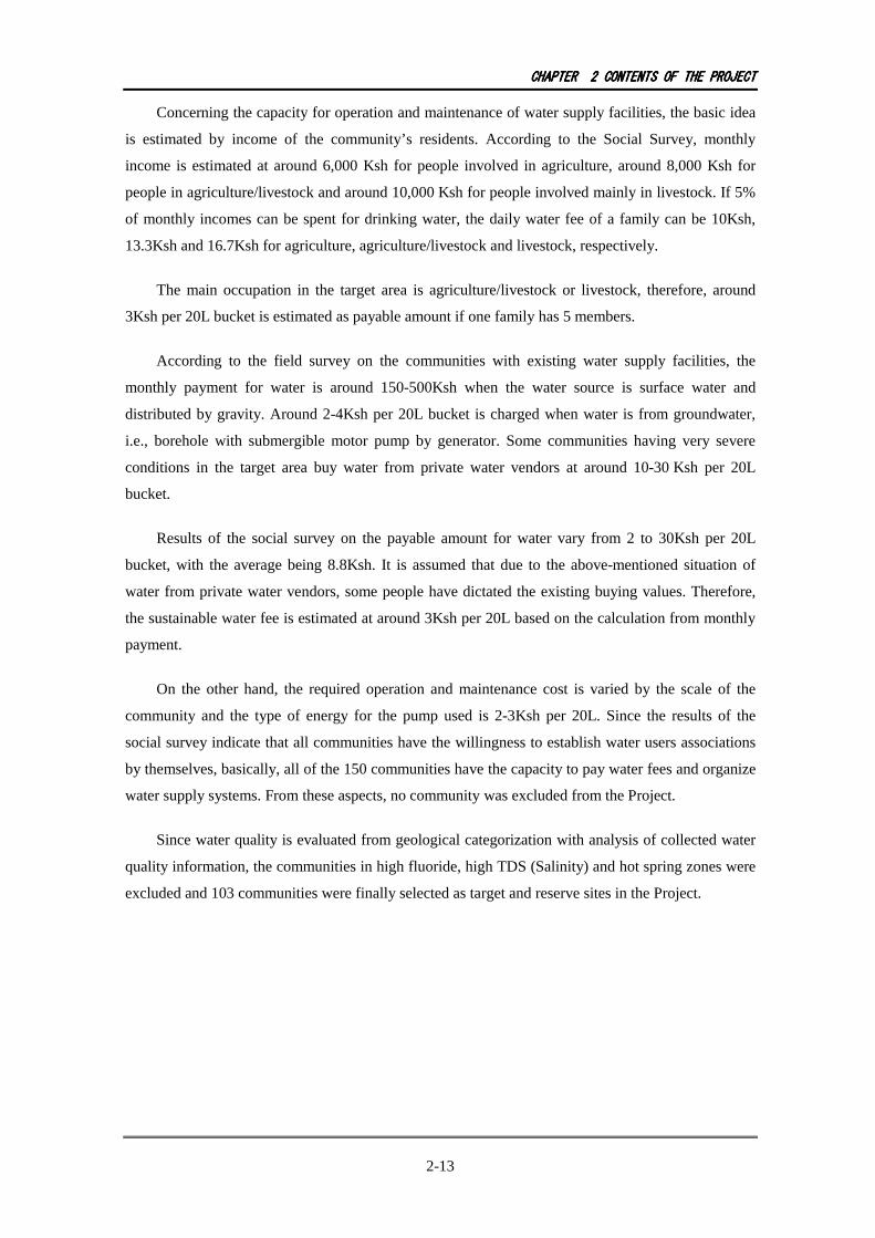
CHAPTERCHAPTERCHAPTERCHAPTER 2222 CONTENTSCONTENTSCONTENTSCONTENTS OFOFOFOF THETHETHETHE PROJECTPROJECTPROJECTPROJECT
2-13
Concerning the capacity for operation and maintenance of water supply facilities, the basic idea
is estimated by income of the community’s residents. According to the Social Survey, monthly
income is estimated at around 6,000 Ksh for people involved in agriculture, around 8,000 Ksh for
people in agriculture/livestock and around 10,000 Ksh for people involved mainly in livestock. If 5%
of monthly incomes can be spent for drinking water, the daily water fee of a family can be 10Ksh,
13.3Ksh and 16.7Ksh for agriculture, agriculture/livestock and livestock, respectively.
The main occupation in the target area is agriculture/livestock or livestock, therefore, around
3Ksh per 20L bucket is estimated as payable amount if one family has 5 members.
According to the field survey on the communities with existing water supply facilities, the
monthly payment for water is around 150-500Ksh when the water source is surface water and
distributed by gravity. Around 2-4Ksh per 20L bucket is charged when water is from groundwater,
i.e., borehole with submergible motor pump by generator. Some communities having very severe
conditions in the target area buy water from private water vendors at around 10-30 Ksh per 20L
bucket.
Results of the social survey on the payable amount for water vary from 2 to 30Ksh per 20L
bucket, with the average being 8.8Ksh. It is assumed that due to the above-mentioned situation of
water from private water vendors, some people have dictated the existing buying values. Therefore,
the sustainable water fee is estimated at around 3Ksh per 20L based on the calculation from monthly
payment.
On the other hand, the required operation and maintenance cost is varied by the scale of the
community and the type of energy for the pump used is 2-3Ksh per 20L. Since the results of the
social survey indicate that all communities have the willingness to establish water users associations
by themselves, basically, all of the 150 communities have the capacity to pay water fees and organize
water supply systems. From these aspects, no community was excluded from the Project.
Since water quality is evaluated from geological categorization with analysis of collected water
quality information, the communities in high fluoride, high TDS (Salinity) and hot spring zones were
excluded and 103 communities were finally selected as target and reserve sites in the Project.

CHAPTERCHAPTERCHAPTERCHAPTER 2222 CONTENTSCONTENTSCONTENTSCONTENTS OFOFOFOF THETHETHETHE PROJECTPROJECTPROJECTPROJECT
2-14
(d) Groundwater(d) Groundwater(d) Groundwater(d) Groundwater
development and drillingdevelopment and drillingdevelopment and drillingdevelopment and drilling
potential are lowpotential are lowpotential are lowpotential are low
Target communities +Target communities +Target communities +Target communities +
reserve communitiesreserve communitiesreserve communitiesreserve communities
Below 40%
(a) Access(a) Access(a) Access(a) Access
to the communityto the communityto the communityto the community
SurveyedSurveyedSurveyedSurveyed
communitiescommunitiescommunitiescommunities
150150150150
(f) Water may contain(f) Water may contain(f) Water may contain(f) Water may contain
flouride or be hotflouride or be hotflouride or be hotflouride or be hot
Excluded from the project
(e)-2 Community capacity(e)-2 Community capacity(e)-2 Community capacity(e)-2 Community capacity
on O & Mon O & Mon O & Mon O & M
(c) Projects by other(c) Projects by other(c) Projects by other(c) Projects by other
donors or national plansdonors or national plansdonors or national plansdonors or national plans
Checks no access
in the area
Checks project
plans in the
area
Communities do
not wish to form
a WUA
Matchs with
the condition
(e)-1 Population below 350(e)-1 Population below 350(e)-1 Population below 350(e)-1 Population below 350
Matchs with
the condition
(b) Existing water supply facility(b) Existing water supply facility(b) Existing water supply facility(b) Existing water supply facility
Checks existing
facilities
STEP2STEP2STEP2STEP2STEP1STEP1STEP1STEP1
(Preselection)(Preselection)(Preselection)(Preselection)
RequestedRequestedRequestedRequested
CommunitiesCommunitiesCommunitiesCommunities
190
(a) Access(a) Access(a) Access(a) Access
to the communityto the communityto the communityto the community
(b) Safty(b) Safty(b) Safty(b) Safty
(c) Projects by other donors or(c) Projects by other donors or(c) Projects by other donors or(c) Projects by other donors or
national plansnational plansnational plansnational plans
DWOchecks
other projjects
Decision by
DWO
DWO checks
conflicts in the
area
Excluded from the
project
Figure 2-2 Selection Flow
Table 2-10 Number of Communities excluded from the Project
District Access
Existing Water Supply Facility
Project by other Donor
Check of house No. by
Satellite data
Potentiality of groundwater
Population less than
350, water level is less than 40m
Operation and Maintenance
Capacity Total
North Baringo
4 0 0 0 1 2 0 8
Baringo Central
1 0 0 0 1 3 0 5
Marigat 1 1 0 2 10 2 0 16 East Pokot
1 0 0 1 14 3 0 19
Total 7 1 0 3 27 10 0 48
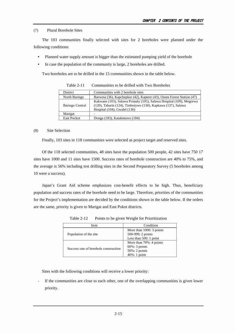
CHAPTERCHAPTERCHAPTERCHAPTER 2222 CONTENTSCONTENTSCONTENTSCONTENTS OFOFOFOF THETHETHETHE PROJECTPROJECTPROJECTPROJECT
2-15
(7) Plural Borehole Sites
The 103 communities finally selected with sites for 2 boreholes were planned under the
following conditions:
• Planned water supply amount is bigger than the estimated pumping yield of the borehole
• In case the population of the community is large, 2 boreholes are drilled.
Two boreholes are to be drilled in the 15 communities shown in the table below.
Table 2-11 Communities to be drilled with Two Boreholes
Distirct Communities with 2 borehole sites North Baringo Barwesa (36), Kapchepkor (42), Kaptere (43), Ossen Forest Station (47)
Baringo Central Kakwane (103), Salawa Primaly (105), Salawa Hospital (109), Mogorwa (120), Tabarin (124), Timboiywo (130), Kapkawa (137), Salawa Hospital (104), Gwalel (136)
Marigat - East Pockot Donga (183), Katakmuwo (184)
(8) Site Selection
Finally, 103 sites in 118 communities were selected as project target and reserved sites.
Of the 118 selected communities, 48 sites have the population 500 people, 42 sites have 750 17
sites have 1000 and 11 sites have 1500. Success rates of borehole construction are 40% to 75%, and
the average is 56% including test drilling sites in the Second Preparatory Survey (5 boreholes among
10 were a success).
Japan’s Grant Aid scheme emphasizes cost-benefit effects to be high. Thus, beneficiary
population and success rates of the borehole need to be large. Therefore, priorities of the communities
for the Project’s implementation are decided by the conditions shown in the table below. If the orders
are the same, priority is given to Marigat and East Pokot districts.
Table 2-12 Points to be given Weight for Prioritization
Item Condition
Population of the site More than 1000: 3 points 500-999: 2 points Less than 500: 1 point
Success rate of borehole construction
More than 70%: 4 points 60%: 3 points 50%: 2 points 40%: 1 point
Sites with the following conditions will receive a lower priority:
- If the communities are close to each other, one of the overlapping communities is given lower
priority.

CHAPTERCHAPTERCHAPTERCHAPTER 2222 CONTENTSCONTENTSCONTENTSCONTENTS OFOFOFOF THETHETHETHE PROJECTPROJECTPROJECTPROJECT
2-16
- If the estimated pumping yield is smaller than the plan of water supply, it is given a lower
priority
On the other hand, each reserved site should bear a certain number to make it easier to make a
follow up if the borehole construction fails as to quantity limit or quality problems. Success rate is
estimated at 56%, and drilling at a site is planned to be done twice; therefore, the number of reserved
sites is as follows:
Success rate if drilling is conducted two times at one site = 1 – 0.44 x 0.44 = 0.80 (80%)
If the construction sites are 100, the number of reserved sites is as follows:
Construction sites: 100
Construction and reserve sites: 100/0.8 = 125
Reserved sites: 25
To construct 100 boreholes as requested, 125 sites need to be secured considering the success
rate. However, only 118 sites were selected from the requested sites. Considering all the above
conditions, 90 sites are targeted to have a construction number with the remaining 28 sites to be the
reserve sites. Five (5) test boreholes drilled under the Second Preparatory Survey were a success, and
were used for the construction of water supply facilities. Then, 85 boreholes were drilled in the
implementation stage. Figure 3 shows the location of target sites while Table 2-13 shows a list of
target and reserve sites.

CHAPTERCHAPTERCHAPTERCHAPTER 2222 CONTENTSCONTENTSCONTENTSCONTENTS OFOFOFOF THETHETHETHE PROJECTPROJECTPROJECTPROJECT
2-17
Figure 2-3 Project Site Location Map
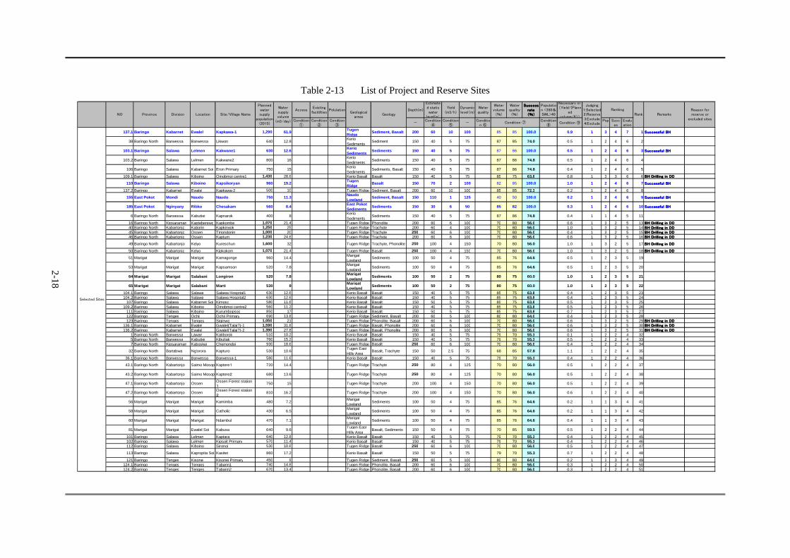
2-18
Table 2-13 List of Project and Reserve Sites
Access
Existing
facitilties
Polulation Depth(m)
Estimate
d static
water
level(m)
Yield
(m3/h)
Dynamic
level(m)
Water
quality
Water
volume
(%)
Water
quality
(%)
SuccessSuccessSuccessSuccess
raterateraterate
(%)(%)(%)(%)
Populatio
n <350&
SWL>40
Necessary nr.
(Yield/(Plann
ed
volume/8))
Condition
①
Condition
②
Condtion
③
-
Condition
④
Condition
⑤
-
Conditio
n ⑥
Condition
⑧
Condition ⑨
Pop
.
Succ
es
Evalu
ation
137.1 Baringo Kabarnet Ewalel Kapkawa-1 1,290 61.9TugenRidge
Sediment, Basalt 200 60 10 100 85 85 100.0 0.9 1 3 4 7 1 Successful BHSuccessful BHSuccessful BHSuccessful BH
38 Baringo North Barwessa Barwessa Likwon 640 12.8KerioSediments
Sediment 150 40 5 75 87 85 74.0 0.5 1 2 4 6 2
103.1 Baringo Salawa Lelmen Kakwane1 630 12.6KerioSediments
Sediments 150 40 5 75 87 86 100.0 0.5 1 2 4 6 3 Successful BHSuccessful BHSuccessful BHSuccessful BH
103.2 Baringo Salawa Lelmen Kakwane2 800 16KerioSediments
Sediments 150 40 5 75 87 86 74.8 0.5 1 2 4 6 4
106 Baringo Salawa Kabarnet Soi Eron Primary 750 15KerioSediments
Sediments, Basalt 150 40 5 75 87 86 74.8 0.4 1 2 4 6 5
109.1 Baringo Salawa Kiboino Oinobmoi centre1 1,430 28.6 Kerio Basalt Basalt 150 40 5 75 85 75 63.8 0.8 1 3 3 6 6 BH Drilling in DDBH Drilling in DDBH Drilling in DDBH Drilling in DD
110 Baringo Salawa Kiboino Kapsikoryan 960 19.2TugenRidge
Basalt 150 70 2 100 82 85 100.0 1.0 1 2 4 6 7 Successful BHSuccessful BHSuccessful BHSuccessful BH
137.2 Baringo Kabarnet Ewalel Kapkawa-2 500 10 Tugen Ridge Sediment, Basalt 200 60 10 100 85 85 72.3 0.2 1 2 4 6 8
155 East Pokot Mondi Naudo Naudo 750 11.3NaudoLowland
Sediment, Basalt 150 110 1 125 40 50 100.0 0.2 1 2 4 6 9 Successful BHSuccessful BHSuccessful BHSuccessful BH
185 East Pokot Nginyany Ribko Chesakam 560 8.4East PokotSediments
Sediments 150 30 6 50 85 82 100.0 0.3 1 2 4 6 10 Successful BHSuccessful BHSuccessful BHSuccessful BH
6 Baringo North Barwessa Kabutiei Kapnarok 400 8KerioSediments
Sediments 150 40 5 75 87 86 74.8 0.4 1 1 4 5 11
16 Baringo North Kipsaraman Kapteberewo Kapkombe 1,070 21.4 Tugen Ridge Phonolite 200 60 6 100 70 80 56.0 0.6 1 3 2 5 13 BH Drilling in DDBH Drilling in DDBH Drilling in DDBH Drilling in DD
40 Baringo North Kabartonjo Katiorin Kapkirwok 1,250 25 Tugen Ridge Trachyte 200 60 4 100 70 80 56.0 1.0 1 3 2 5 14 BH Drilling in DDBH Drilling in DDBH Drilling in DDBH Drilling in DD
45 Baringo North Kabartonjo Ossen Tiriondonin 1,000 20 Tugen Ridge Trachyte 250 60 6 100 70 80 56.0 0.4 1 3 2 5 15 BH Drilling in DDBH Drilling in DDBH Drilling in DDBH Drilling in DD
46 Baringo North Kabartonjo Ossen Kaptum 1,230 24.6 Tugen Ridge Trachyte 200 60 6 100 70 80 56.0 0.6 1 3 2 5 16 BH Drilling in DDBH Drilling in DDBH Drilling in DDBH Drilling in DD
49 Baringo North Kabartonjo Kelyo Kureschun 1,600 32 Tugen Ridge Trachyte, Phonolite 250 100 4 150 70 80 56.0 1.0 1 3 2 5 17 BH Drilling in DDBH Drilling in DDBH Drilling in DDBH Drilling in DD
50 Baringo North Kabartonjo Kelyo Kipkokom 1,070 21.4 Tugen Ridge Basalt 250 100 4 150 70 80 56.0 1.0 1 3 2 5 18 BH Drilling in DDBH Drilling in DDBH Drilling in DDBH Drilling in DD
51 Marigat Marigat Marigat Kamagonge 960 14.4MarigatLowland
Sediments 100 50 4 75 85 76 64.6 0.5 1 2 3 5 19
53 Marigat Marigat Marigat Kapsamson 520 7.8MarigatLowland
Sediments 100 50 4 75 85 76 64.6 0.5 1 2 3 5 20
64 Marigat Marigat Salabani Longiron 520 7.8MarigatLowland
Sediments 100 50 2 75 80 75 60.0 1.0 1 2 3 5 21
65 Marigat Marigat Salabani Marti 530 8MarigatLowland
Sediments 100 50 2 75 80 75 60.0 1.0 1 2 3 5 22
104.1 Baringo Salawa Salawa Salawa Hospital1 630 12.6 Kerio Basalt Basalt 150 40 5 75 85 75 63.8 0.4 1 2 3 5 23104.2 Baringo Salawa Salawa Salawa Hospital2 630 12.6 Kerio Basalt Basalt 150 40 5 75 85 75 63.8 0.4 1 2 3 5 24
107 Baringo Salawa Kabarnet Soi Kimoso 580 11.6 Kerio Basalt Basalt 150 50 5 75 85 75 63.8 0.5 1 2 3 5 25109.2 Baringo Salawa Kiboino Oinobmoi centre2 560 11.2 Kerio Basalt Basalt 150 40 5 75 85 75 63.8 0.5 1 2 3 5 26
111 Baringo Salawa Kiboino Kurumbopsoo 850 17 Kerio Basalt Basalt 150 50 5 75 85 75 63.8 0.7 1 2 3 5 27122 Baringo Tenges Ochii Ochii Primary 690 13.8 Tugen Ridge Sediment, Basalt 200 60 5 100 80 80 64.0 0.4 1 2 3 5 28123 Baringo Tenges Tenges Siginwo 1,050 21 Tugen Ridge Phonolite, Basalt 200 60 6 100 70 80 56.0 0.6 1 3 2 5 29 BH Drilling in DDBH Drilling in DDBH Drilling in DDBH Drilling in DD
136.1 Baringo Kabarnet Ewalel Gwalel(Talai?)-1 1,590 31.8 Tugen Ridge Basalt, Phonolite 200 60 6 100 70 80 56.0 0.6 1 3 2 5 30 BH Drilling in DDBH Drilling in DDBH Drilling in DDBH Drilling in DD
136.2 Baringo Kabarnet Ewalel Gwalel(Talai?)-2 1,390 27.8 Tugen Ridge Basalt, Phonolite 200 60 6 100 70 80 56.0 0.6 1 3 2 5 31 BH Drilling in DDBH Drilling in DDBH Drilling in DDBH Drilling in DD
1 Baringo North Barwessa Lawan Katiborok 510 10.2 Kerio Basalt Basalt 150 40 5 75 79 70 55.3 0.1 1 2 2 4 325 Baringo North Barwessa Kabutiei Kibuliak 760 15.2 Kerio Basalt Basalt 150 40 5 75 79 70 55.3 0.5 1 2 2 4 337 Baringo North Kipsaraman Kaboskei Chemondoi 930 18.6 Tugen Ridge Basalt 250 60 6 100 70 80 56.0 0.4 1 2 2 4 34
32 Baringo North Bartabwa Ng'orora Kapturo 530 10.6Tugen EastHilly Area
Basalt, Trachyte 150 50 2.5 75 68 85 57.8 1.1 1 2 2 4 35
36.1 Baringo North Barwessa Barwessa Barwessa-1 580 11.6 Kerio Basalt Basalt 150 40 5 75 79 70 55.3 0.4 1 2 2 4 36
43.1 Baringo North Kabartonjo Saimo Mosop Kaptere1 720 14.4 Tugen Ridge Trachyte 250 80 4 125 70 80 56.0 0.5 1 2 2 4 37
43.2 Baringo North Kabartonjo Saimo Mosop Kaptere2 680 13.6 Tugen Ridge Trachyte 250 80 4 125 70 80 56.0 0.5 1 2 2 4 38
47.1 Baringo North Kabartonjo Ossen Ossen Forest station1
750 15 Tugen Ridge Trachyte 200 100 4 150 70 80 56.0 0.5 1 2 2 4 39
47.2 Baringo North Kabartonjo OssenOssen Forest station2
810 16.2 Tugen Ridge Trachyte 200 100 4 150 70 80 56.0 0.6 1 2 2 4 40
56 Marigat Marigat Marigat Kamimba 480 7.2MarigatLowland
Sediments 100 50 4 75 85 76 64.6 0.2 1 1 3 4 41
58 Marigat Marigat Marigat Catholic 430 6.5MarigatLowland
Sediments 100 50 4 75 85 76 64.6 0.2 1 1 3 4 42
60 Marigat Marigat Marigat Ndambul 470 7.1MarigatLowland
Sediments 100 50 4 75 85 76 64.6 0.4 1 1 3 4 43
81 Marigat Marigat Ewalel Soi Kabusa 640 9.6Tugen EastHilly Area
Basalt, Sediments 150 50 4 75 70 85 59.5 0.5 1 2 2 4 44
101 Baringo Salawa Lelmen Kaptara 640 12.8 Kerio Basalt Basalt 150 40 5 75 79 70 55.3 0.4 1 2 2 4 45102 Baringo Salawa Lelmen Kipsoit Primary 570 11.4 Kerio Basalt Basalt 150 40 5 75 79 70 55.3 0.4 1 2 2 4 46112 Baringo Salawa Kiboino Sironoi 530 10.6 Tugen Ridge Basalt 250 60 6 100 70 80 56.0 0.5 1 2 2 4 47
113 Baringo Salawa Kapropita Soi Kasitet 860 17.2 Kerio Basalt Basalt 150 50 5 75 79 70 55.3 0.7 1 2 2 4 48
121 Baringo Tenges Kisonei Kisonei Primary 450 9 Tugen Ridge Sediment, Basalt 250 60 5 100 80 80 64.0 0.2 1 1 3 4 49124.1 Baringo Tenges Tenges Tabarin1 740 14.8 Tugen Ridge Phonolite, Basalt 200 60 6 100 70 80 56.0 0.3 1 2 2 4 50124.2 Baringo Tenges Tenges Tabarin2 670 13.4 Tugen Ridge Phonolite, Basalt 200 60 6 100 70 80 56.0 0.3 1 2 2 4 51
Remarks
Reason for
reserve or
excluded sites
Judging
1:Selected
2:Reserve
3:Exclude
4:Exclude
Ranking
Rank
Condition ⑦
NO Province Division Location GeologySite/Village Name
Planned
water
supply
population
(2015)
Water
supply
volume
(m3/day)
Geological
areas
Selected Sites

2-19
Access
Existing
facitilties
Polulation Depth(m)
Estimate
d static
water
level(m)
Yield
(m3/h)
Dynamic
level(m)
Water
quality
Water
volume
(%)
Water
quality
(%)
SuccessSuccessSuccessSuccess
raterateraterate
(%)(%)(%)(%)
Populatio
n <350&
SWL>40
Necessary nr.
(Yield/(Plann
ed
volume/8))
Condition
①
Condition
②
Condtion
③
-
Condition
④
Condition
⑤
-
Conditio
n ⑥
Condition
⑧
Condition ⑨
Pop
.
Succ
es
Evalu
ation
125 Baringo Tenges Tuluongoi Tuluongoi 980 19.6 Tugen Ridge Sediment, Basalt 200 60 6 100 70 80 56.0 0.4 1 2 2 4 52
126 Baringo Tenges Tuluongoi Tebei 880 17.6Tugen EastHilly Area
Sediment, Basalt 150 50 4 75 70 85 59.5 0.9 1 2 2 4 53
129 Baringo Tenges Bekibon Tinomoi 940 18.8Tugen EastHilly Area
Sediment, Basalt 250 70 4 100 65 85 55.3 0.6 1 2 2 4 54
130.1 Baringo Sacho Kabasis Timboiywo1 680 13.6 Tugen Ridge Sediment, Basalt 200 60 6 100 70 80 56.0 0.3 1 2 2 4 55130.2 Baringo Sacho Kabasis Timboiywo2 750 15 Tugen Ridge Sediment, Basalt 200 60 6 100 70 80 56.0 0.3 1 2 2 4 56
133 Baringo Kabarnet Orokwo Kapchomuswo Sec 590 11.8 Tugen Ridge Sediment, Basalt 200 60 6 100 70 80 56.0 0.3 1 2 2 4 57139 Baringo Kabarnet Riwo Serei 510 10.2 Tugen Ridge Basalt, Phonolite 200 60 6 100 70 80 56.0 0.5 1 2 2 4 58
183.1 East Pokot NginyanyNginyanWest
Donge 580 8.7East PokotBasalt
Basalt, Tuff 150 60 1.5 75 70 75 52.5 1.3 1 2 2 4 59
183.2 East Pokot NginyanyNginyanWest
Donge 850 12.8East PokotBasalt
Basalt, Tuff 150 60 1.5 75 70 75 52.5 1.3 1 2 2 4 60
184.1 East Pokot Nginyany Kositei Katukumwo1 670 10.1Tugen EastHilly Area
Trachyte 150 50 4 75 70 85 59.5 0.5 1 2 2 4 61
184.2 East Pokot Nginyany Kositei Katukumwo2 670 10.1Tugen EastHilly Area
Trachyte 150 50 4 75 70 85 59.5 0.5 1 2 2 4 62
186 East Pokot Nginyany Ribko Chesitet 440 6.6East PokotSediments
Sediments,Trachyte
150 30 6 50 80 82 65.6 0.2 1 1 3 4 63
2 Baringo North Barwessa Lawan Konoo 480 9.6 Kerio Basalt Basalt 150 40 5 75 79 70 55.3 0.2 1 1 2 3 643 Baringo North Barwessa Lawan Kormor 350 7 Kerio Basalt Basalt 150 40 5 75 79 70 55.3 0.4 1 1 2 3 65
10 Baringo North Kipsaraman Kaboskei Moigutwo 420 8.4 Tugen Ridge Tuff, Shale 200 60 6 100 70 80 56.0 0.3 1 1 2 3 66
12 Baringo North BarwessaKaboskeiKerio
Ayatia 380 7.6 Kerio Basalt Basalt 150 40 5 75 79 70 55.3 0.4 1 1 2 3 67
13 Baringo North BarwessaKaboskeiKerio
KaboskeiKerio/Marigut
480 9.6 Kerio Basalt Basalt 150 30 5 50 79 70 55.3 0.2 1 1 2 3 68
28 Baringo North Kipsaraman Sibilo Kolongotwo 450 9Tugen EastHilly Area
Basalt 150 40 4 75 70 85 59.5 0.5 1 1 2 3 69
29 Baringo North Kipsaraman Sibilo Koibaware 430 8.6Tugen EastHilly Area
Basalt 150 40 4 75 70 85 59.5 0.5 1 1 2 3 70
31 Baringo North Kipsaraman Sibilo Chemorongion 370 7.4Tugen EastHilly Area
Basalt, Trachyte 150 50 4 75 70 85 59.5 0.5 1 1 2 3 71
33 Baringo North Bartabwa Ng'orora Rondinir 450 9Tugen EastHilly Area
Bassalt, Tuff 150 50 4 75 70 85 59.5 0.5 1 1 2 3 72
36.2 Baringo North Barwessa Barwessa Barwessa-2 430 8.6 Kerio Basalt Basalt 150 40 5 75 79 70 55.3 0.4 1 1 2 3 7339 Baringo North Kabartonjo Katiorin Seremwo 430 8.6 Tugen Ridge Trachyte 250 60 3 100 70 80 56.0 0.6 1 1 2 3 74
69 Marigat Marigat Kimalel Kapkechii 360 5.4Tugen EastHilly Area
Basalt 150 50 4 75 70 85 59.5 0.4 1 1 2 3 76
72 Marigat Marigat Kimalel Kimalel Hospital 400 6Tugen EastHilly Area
Basalt 250 50 2 75 70 85 59.5 0.5 1 1 2 3 77
74 Marigat Marigat Kimalel Lokoiwopsonchun 400 6Tugen EastHilly Area
Basalt 150 50 2 75 70 85 59.5 0.5 1 1 2 3 79
75 Marigat Marigat Kimalel Kinyach 360 5.4Tugen EastHilly Area
Phonolite 250 50 2 75 70 85 59.5 0.7 1 1 2 3 80
77 Marigat Marigat Kimondis Tirng'ongwonin 370 5.6Tugen EastHilly Area
Basalt 150 50 2 75 65 85 55.3 0.7 1 1 2 3 81
78 Marigat Marigat Kimondis Kibingor 480 7.2Tugen EastHilly Area
Basalt 150 50 2 75 65 85 55.3 0.7 1 1 2 3 82
114 Baringo Salawa Kapropita Soi Sichei 370 7.4 Kerio Basalt Basalt 150 50 5 75 79 70 55.3 0.4 1 1 2 3 83
119 Baringo Sacho Chepkero Chepkero Primary 480 9.6 Kerio Basalt Sediment, Basalt 150 70 5 100 79 70 55.3 0.4 1 1 2 3 84120.1 Baringo Tenges Kisonei Mogorwa 410 8.2 Kerio Basalt Sediment, Basalt 150 50 2.5 75 79 70 55.3 0.5 1 1 2 3 85120.2 Baringo Tenges Kisonei Mogorwa 410 8.2 Kerio Basalt Sediment, Basalt 150 50 2.5 75 79 70 55.3 0.7 1 1 2 3 86
127 Baringo Tenges Tuluongoi Ilyakat 400 8Tugen EastHilly Area
Phonolite, Basalt 150 50 4 75 70 85 59.5 0.5 1 1 2 3 87
134 Baringo Kabarnet Orokwo Kiwanja Ndege 490 9.8 Tugen Ridge Sediment, Basalt 200 60 6 100 70 80 56.0 0.3 1 1 2 3 88135 Baringo Kabarnet Orokwo Pemwai centre 460 9.2 Tugen Ridge Basalt, Phonolite 200 60 6 100 70 80 56.0 0.2 1 1 2 3 89140 Baringo Kabarnet Kituro Turupkir 390 7.8 Tugen Ridge Phonolite, Basalt 200 60 4 100 70 80 56.0 0.3 1 1 2 3 90
187 East Pokot Nginyany Ribko Kasakaram 600 9East PokotBasalt
Trachyte 150 60 0.6 75 70 75 52.5 3.3 1 2 2 4 92
182 East Pokot Nginyany Ribko Chepanda 430 6.5East PokotBasalt
Basalt, Tuff 150 60 1 75 70 75 52.5 1.4 1 1 2 3 93
179 East Pokot Churo Kaptuya Lomerimeri 380 5.7MochingaiHighland
Phonolite 250 60 2 100 63 80 50.4 0.7 1 1 2 3 95
Remarks
Reason for
reserve or
excluded sites
Judging
1:Selected
2:Reserve
3:Exclude
4:Exclude
Ranking
Rank
Condition ⑦
NO Province Division Location GeologySite/Village Name
Planned
water
supply
population
(2015)
Water
supply
volume
(m3/day)
Geological
areas
Selected Sites

2-20
Access
Existing
facitilties
Polulation Depth(m)
Estimate
d static
water
level(m)
Yield
(m3/h)
Dynamic
level(m)
Water
quality
Water
volume
(%)
Water
quality
(%)
SuccessSuccessSuccessSuccess
raterateraterate
(%)(%)(%)(%)
Populatio
n <350&
SWL>40
Necessary nr.
(Yield/(Plann
ed
volume/8))
Condition
①
Condition
②
Condtion
③
-
Condition
④
Condition
⑤
-
Conditio
n ⑥
Condition
⑧
Condition ⑨
Pop
.
Succ
es
Evalu
ation
44 Baringo North Kabartonjo Saimo Mosop Boin 430 8.6 Tugen Ridge Trachyte 250 80 4 125 70 80 56.0 2Rsv. 1 2 3 75 reserve Local condition
116 Baringo Sacho Kapkelelwa Katunoi 430 8.6 Kerio Basalt Sediment, Basalt 150 50 5 75 79 70 55.3 0.4 2Rsv. 1 2 3 91 reserve Local condition
35 Baringo North Bartabwa Ng'orora Chemoe 480 9.6Tugen EastHilly Area
Trachyte 150 50 2.5 75 60 85 51.0 0.7 2Rsv. 1 2 3 94 reserve
Priority reservesite for DD
159 East Pokot Mondi Silale Cheptunoyo 390 5.9East PokotCentralLowland
Basalt, Welded tuff 150 50 3 75 60 70 42.0 0.3 2Rsv. 1 2 3 96 reserve Success rate
90 Marigat Mochongoi Mochongoi Kapkechir 730 11MochingaiHighland
Phonolite 250 80 2 125 50 80 40.0 0.7 2Rsv. 2 2 4 97 reserve Success rate
92 Marigat Mochongoi Mochongoi Kipkandule 550 8.3MochingaiHighland
Phonolite 250 80 2 125 50 80 40.0 0.7 2Rsv. 2 2 4 98 reserve Success rate
95 Marigat Mochongoi Chebinyiny Nyalilbuch 760 11.4MochingaiHighland
Sediments, Basalt 200 60 2 100 50 80 40.0 1.0 2Rsv. 2 2 4 99 reserve Success rate
98 Marigat Mochongoi Arabal Menmeno 610 9.2MochingaiHighland
Sediments, Basalt 150 60 2 100 50 80 40.0 1.0 2Rsv. 2 2 4 100 reserve Success rate
150 East Pokot Tangulbei Kokwototo Katungura 530 8MochingaiHighland
Sediment, Basalt 200 60 2 100 50 80 40.0 1.0 2Rsv. 2 2 4 101 reserve Success rate
86 Marigat Marigat Sandai Samuran 480 7.2MochingaiHighland
Basalt 150 60 4 100 50 80 40.0 0.4 2Rsv. 1 2 3 102 reserve Success rate
89 Marigat Mochongoi Mochongoi Mochongoi centre 450 6.8MochingaiHighland
Phonolite 250 80 2 125 50 80 40.0 0.5 2Rsv. 1 2 3 103 reserve Success rate
94 Marigat Mochongoi Chebinyiny Sambaka 490 7.4MochingaiHighland
Sediments, Basalt 250 60 2 100 50 80 40.0 0.7 2Rsv. 1 2 3 104 reserve Success rate
96 Marigat Mochongoi Arabal Sokonin 390 5.9MochingaiHighland
Basalt 150 60 2 100 50 80 40.0 0.7 2Rsv. 1 2 3 105 reserve Success rate
145 East Pokot Tangulbei Korosi Nakolete 380 5.7MochingaiHighland
Sediment, Basalt 250 60 2 100 50 80 40.0 0.7 2Rsv. 1 2 3 106 reserve Success rate
146 East Pokot Tangulbei Tangulbei Kalapata 350 5.3MochingaiHighland
Sediment, Basalt 200 60 2 100 50 80 40.0 0.7 2Rsv. 1 2 3 107 reserve Success rate
149 East Pokot Tangulbei Orus Siria 370 5.6MochingaiHighland
Trachyte, Weldedtuff
200 60 1 100 50 80 40.0 1.4 2Rsv. 1 2 3 108 reserve
Success rate
Expected water
volume shortage
156 East Pokot Mondi Naudo Akwichatis 1,000 15MochingaiHighland
Sediment, Basalt 250 60 2 100 50 80 40.0 1.4 2Rsv. 3 2 5 109 reserve
Success rate
Expected water
volume shortage
157 East Pokot Mondi Naudo Nasorot 1,000 15MochingaiHighland
Sediment, Basalt 200 60 2 100 50 80 40.0 1.4 2Rsv. 3 2 5 110 reserve
Success rate
Expected water
volume shortage
26 Baringo North Kabartonjo Bartum Barkilach 430 8.6Tugen EastHilly Area
Basalt 150 50 1 75 60 85 51.0 1.8 2Rsv. 1 2 3 111 reserve
Expected water
volume shortage
27 Baringo North Kabartonjo Bartum Usuonin 380 7.6Tugen EastHilly Area
Basalt 150 50 1 75 60 85 51.0 1.8 2Rsv. 1 2 3 112 reserve
Expected water
volume shortage
30 Baringo North Kipsaraman Sibilo Chepkewel 380 7.6Tugen EastHilly Area
Basalt 150 50 1 75 62 85 52.7 1.8 2Rsv. 1 2 3 113 reserve
Expected water
volume shortage
15 Baringo North Kipsaraman Kapteberewo Kapamin 750 15 Tugen Ridge Phonolite 250 60 1 100 70 80 56.0 1.9 2Rsv. 2 2 4 114 reserve
Expected water
volume shortage
42.1 Baringo North Kabartonjo Saimo Mosop Kapchepkor1 660 13.2 Tugen Ridge Trachyte 250 80 4 125 70 80 56.0 0.5 2Rsv. 2 2 4 117 Reserve for 43.1
Overlapping with
another site
42.2 Baringo North Kabartonjo Saimo Mosop Kapchepkor2 790 15.8 Tugen Ridge Trachyte 250 80 4 125 70 80 56.0 0.6 2Rsv. 2 2 4 118 Reserve for 43.2の
Overlapping with
another site
48 Baringo North Kabartonjo Kelyo Kaptumin 1,280 25.6 Tugen Ridge Trachyte 200 100 4 150 60 80 48.0 1.0 2Rsv. 3 2 5 119 Reserve for 49,50
Another sitewithin 2km,success rate
105.1 Baringo Salawa Salawa Salawa Primary1 970 19.4 Kerio Basalt Basalt 150 40 5 75 85 75 63.8 0.5 2Rsv. 2 3 5 120 Reserve for 104.1
Overlapping with
another site
105.2 Baringo Salawa Salawa Salawa Primary2 890 17.8 Kerio Basalt Basalt 150 40 5 75 85 75 63.8 0.5 2Rsv. 2 3 5 121 Reserve for 104.2
Overlapping with
another site
108 Baringo Salawa Kabarnet Soi Saonin 530 10.6 Kerio Basalt Basalt 150 40 5 75 85 75 63.8 0.5 2Rsv. 2 3 5 122 Reserve for 109
Overlapping with
another site
Remarks
Reason for
reserve or
excluded sites
Judging
1:Selected
2:Reserve
3:Exclude
4:Exclude
Ranking
Rank
Condition ⑦
NO Province Division Location GeologySite/Village Name
Planned
water
supply
population
(2015)
Water
supply
volume
(m3/day)
Geological
areas
Reserve Sites

2-21
Access
Existing
facitilties
Polulation Depth(m)
Estimate
d static
water
level(m)
Yield
(m3/h)
Dynamic
level(m)
Water
quality
Water
volume
(%)
Water
quality
(%)
SuccessSuccessSuccessSuccess
raterateraterate
(%)(%)(%)(%)
Populatio
n <350&
SWL>40
Necessary nr.
(Yield/(Plann
ed
volume/8))
Condition
①
Condition
②
Condtion
③
-
Condition
④
Condition
⑤
-
Conditio
n ⑥
Condition
⑧
Condition ⑨
Pop
.
Succ
es
Evalu
ation
Sites not
Selected
11 Baringo North BarwessaKaboskeiKerio
Katikit 300 6KerioSediments
Sediments 120 40 5 75 87 85 74.0 3Exd. 1 4 5 12 Small population
73 Marigat Marigat Kimalel Kisamisonchun 320 4.8Tugen EastHilly Area
Basalt 120 40 1 50 70 85 59.5 3Exd. 1 2 3 78 Small population
62 Marigat Marigat Eldume Ilchurai 290 4.4MarigatLowland
Sediments 100 40 4 75 85 76 64.6 0.3 3Exd. 1 3 4 115 Small population
168 East Pokot Kolowa Loiwat Chepelion 260 3.9East PokotBasalt
Basalt 120 40 0.6 75 70 60 42.0 0.7 3Exd. 1 2 3 116 Success rate
63 Marigat Marigat Eldume Eldume centre 710 10.7Marigat EastLowland
Sediments 100 30 4 50 Treated 80 25 20.0 0.4 3Exd. 2 0 2 123 Water quality
84 Marigat Marigat Loboi Chelaba 510 7.7Marigat EastLowland
Basalt 100 40 4 75 Treated 80 25 20.0 3Exd. 2 0 2 124 Water quality
88 Marigat Mukutani Kiserian Logumgum 960 14.4Marigat EastLowland
Sediments 50 30 2 50 Treated 80 25 20.0 1.4 3Exd. 2 0 2 125 Water quality
154 East Pokot Mondi Naudo Riongo 640 9.6NaudoLowland
Sediment, Basalt,Welded tuff
150 110 1 125 Inaccep
table
40 50 20.0 3Exd. 2 0 2 126 Fluoride
61 Marigat Marigat Eldume Abori 420 6.3Marigat EastLowland
Sediments 50 30 2 50 Treated 80 25 20.0 3Exd. 1 0 1 127 Water quality
67 Marigat Marigat Ng'ambo Lesuuwa 370 5.6Marigat EastLowland
Sediments 50 30 2 50 Inaccep
table
80 25 20.0 3Exd. 1 0 1 128 Fluoride
70 Marigat Marigat Kimalel Loropil 430 6.5Marigat EastLowland
Sediments 50 30 1 50 Inaccep
table
80 25 20.0 3Exd. 1 0 1 129 Fluoride
83 Marigat Marigat Loboi Kiwanja Ndege 360 5.4Marigat EastLowland
Sediments 50 30 2 50 Inaccep
table
80 25 20.0 3Exd. 1 0 1 130 Fluoride
85 Marigat Marigat Sandai Chepkotoiyan 400 6Marigat EastLowland
Sediments 50 30 2 50 Inaccep
table
80 25 20.0 3Exd. 1 0 1 131 Fluoride
87 Marigat Mukutani Kiserian Mosuro 380 5.7Marigat EastLowland
Sediments 50 30 2 50 Inaccep
table
80 25 20.0 3Exd. 1 0 1 132 Fluoride
141 East Pokot Tangulbei Orus Lalwasoyen 300 4.5NaudoLowland
Sediment, Basalt 150 110 1 125 Inaccep
table
40 50 20.0 Excluded 3Exd. 1 0 1 133 Fluoride
165 East Pokot Kolowa Ng'oron Ngoron 810 12.2PrecambrianGneiss
Gneiss 150 40 0.5 75 30 75 22.5 3Exd. 2 0 2 134 Success rate
163 East Pokot Kolowa Kolowa Chepturu 370 5.6PrecambrianGneiss
Gneiss 150 40 0.6 75 30 75 22.5 3Exd. 1 0 1 135 Success rate
169 East Pokot Kolowa Kipnai Krelion 360 5.4PrecambrianGneiss
Gneiss 150 50 0.5 75 30 75 22.5 3Exd. 1 0 1 136 Success rate
190 East Pokot Nginyany Ribko Maron 370 5.6PrecambrianGneiss
Phonolite, Gneiss 250 40 0.5 75 30 75 22.5 3Exd. 1 0 1 137 Success rate
66 Marigat Marigat Salabani Kampi ya Samaki 1,390 20.9MarigatLowland
Trachyte, Tuff 100 50 4 75 Treated 50 60 30.0 3Exd. 3 0 3 138 Water quality
24.1 Baringo North Bartabwa Kinyach Toboroi 620 12.4East PokotBasalt
Phonolite 200 50 2 75 40 75 30.0 1.0 3Exd. 2 0 2 139 Success rate
24.2 Baringo North Bartabwa Kinyach Toboroi 620 12.4East PokotBasalt
Phonolite 200 50 2 75 40 75 30.0 1.0 3Exd. 2 0 2 140 Success rate
Sites not
Selected
25 Baringo North Kabartonjo Bartum Lingok 300 6Tugen EastHilly Area
Trachyte 120 60 4 75 50 60 30.0 Excluded 3Exd. 1 0 1 141Small
population/HP
imp.
144 East Pokot Tangulbei Tangulbei Lomuyek 400 6East PokotCentralLowland
Basalt 120 50 0.5 100 Inaccep
table
50 60 30.0 3Exd. 1 0 1 142 Fluoride
181 East Pokot Nginyany Kositei Katikit 1,120 16.8East PokotBasalt
Tuff 120 60 1 75 70 50 35.0 3Exd. 3 0 3 143 Water quality
151 East Pokot Mondi Loruk Tuwo 560 8.4East PokotCentralLowland
Sediment, Basalt 150 70 3 100 Inaccep
table
60 60 36.0 3Exd. 2 0 2 144 Fluoride
152 East Pokot Mondi Loruk Lemuyek 750 11.3East PokotCentralLowland
Basalt 150 70 3 100 Inaccep
table
60 60 36.0 3Exd. 2 0 2 145 Fluoride
153 East Pokot Mondi Loruk Chebilat 750 11.3East PokotCentralLowland
Sediment, Basalt 180 70 3 100 Inaccep
table
60 60 36.0 3Exd. 2 0 2 146 Fluoride
160 East Pokot Mondi Loyamorok Kosiokon 750 11.3East PokotSediments
Sediment,Trachyphonolite
120 30 6 50 60 60 36.0 0.3 3Exd. 2 0 2 147 Success rate
171 East Pokot Churo Churo Naminito 550 8.3MochingaiHighland
Phonolite 180 60 1 100 45 80 36.0 3Exd. 2 0 2 148 Success rate
143 East Pokot Tangulbei Tangulbei Kiliwok 440 6.6East PokotCentral
Basalt 120 50 3 100 Inaccep
table
65 60 39.0 3Exd. 1 0 1 149 Fluoride
148 East Pokot Tangulbei Orus Orus 390 5.9MochingaiHighland
Basalt, Welded tuff 180 60 2 100 50 80 40.0 3Exd. 1 2 3 150 Small community
131 Baringo Sacho Kabasis Kabasis 1,650 33 Tugen Ridge Sediment, Basalt 200 60 6 100 55 80 44.0 3Exd. 3 2 5 151 Test drilling fail
Success rate
176 East Pokot Churo Churo Komolwo 280 4.2MochingaiHighland
Phonolite 180 60 2 100 63 80 50.4 Excluded 3Exd. 1 2 3 152Small
population/HP
imp.
79 Marigat Marigat Kimondis Wokerben 480 7.2Tugen EastHilly Area
Basalt 120 50 2 75 65 85 55.3 0.7 3Exd. 1 2 3 153 Small community
115 Baringo Salawa Kapropita Soi Kisok 270 5.4 Kerio Basalt Basalt 130 50 5 75 79 70 55.3 Excluded 3Exd. 1 2 3 154Small
population/HP
imp.
117 Baringo Sacho Kapkelelwa Saimet 320 6.4 Kerio Basalt Basalt 150 60 5 100 79 70 55.3 Excluded 3Exd. 1 2 3 155Small
population/HP
imp.
82 Marigat Marigat Ewalel Soi Barsemoi 530 8 有り
Tugen EastHilly Area
Basalt 120 50 4 75 70 85 59.5 3Exd. 2 2 4 156 Existing facility
68 Marigat Marigat Kimalel Kipchemei 400 6Tugen EastHilly Area
Basalt 120 50 4 75 70 85 59.5 0.4 3Exd. 1 2 3 157 Small community
128 Baringo Tenges Tuluongoi Katkamuma 220 4.4Tugen EastHilly Area
Basalt 120 50 4 75 70 85 59.5 Excluded 3Exd. 1 2 3 158Small
population/HP
imp.
54 Marigat Marigat Marigat Sirinyo 360 5.4MarigatLowland
Sediments 100 50 4 75 85 76 64.6 0.4 3Exd. 1 3 4 159 Small community
97 Marigat Mochongoi Arabal Partalo 520 7.8 不可
MochingaiHighland
Basalt 150 60 2 100 50 80 40.0 4Exd. 2 2 4 160 Inaccessible
Site unknown
17 Baringo North Kipsaraman Kapteberewo Chambai Primary 690 13.8 不可 Phonolite 200 80 0 - - - 4Exd. 2 161 Inaccessible
14 Baringo North BarwessaKaboskeiKerio
Chesangich 370 7.4 不可 0 0 - - - 4Exd. 1 162 Inaccessible
19 Baringo North Kipsaraman Kipkata Barketieu Primary 430 8.6 不可 0 0 - - - 4Exd. 1 163 Inaccessible
41 Baringo North Kabartonjo Katiorin Kapkomol 320 6.4 不可 0 0 - - - 4Exd. 1 164 Inaccessible
118 Baringo Sacho Chepkero Kwamkeiyon 370 7.4 不可 0 0 - - - 4Exd. 1 165 Inaccessible
178 East Pokot Churo Kaptuya Lolkos 280 4.2 不可 0 0 - - - 4Exd. 1 166 Inaccessible
TotalTotalTotalTotal 98,170 166
90 sites90 sites90 sites90 sites 59,580 0 1 0 0 73.4 77.3 58.7 0 1=90 BH Drilling=10Incl. reserveIncl. reserveIncl. reserveIncl. reserve
sitessitessitessites
(118)(118)(118)(118)
76,460 70707070 78787878 56565656 118-5118-5118-5118-5
60.7%
Remarks
Reason for
reserve or
excluded sites
Judging
1:Selected
2:Reserve
3:Exclude
4:Exclude
Ranking
Rank
Condition ⑦
NO Province Division Location GeologySite/Village Name
Planned
water
supply
population
(2015)
Water
supply
volume
(m3/day)
Geological
areas
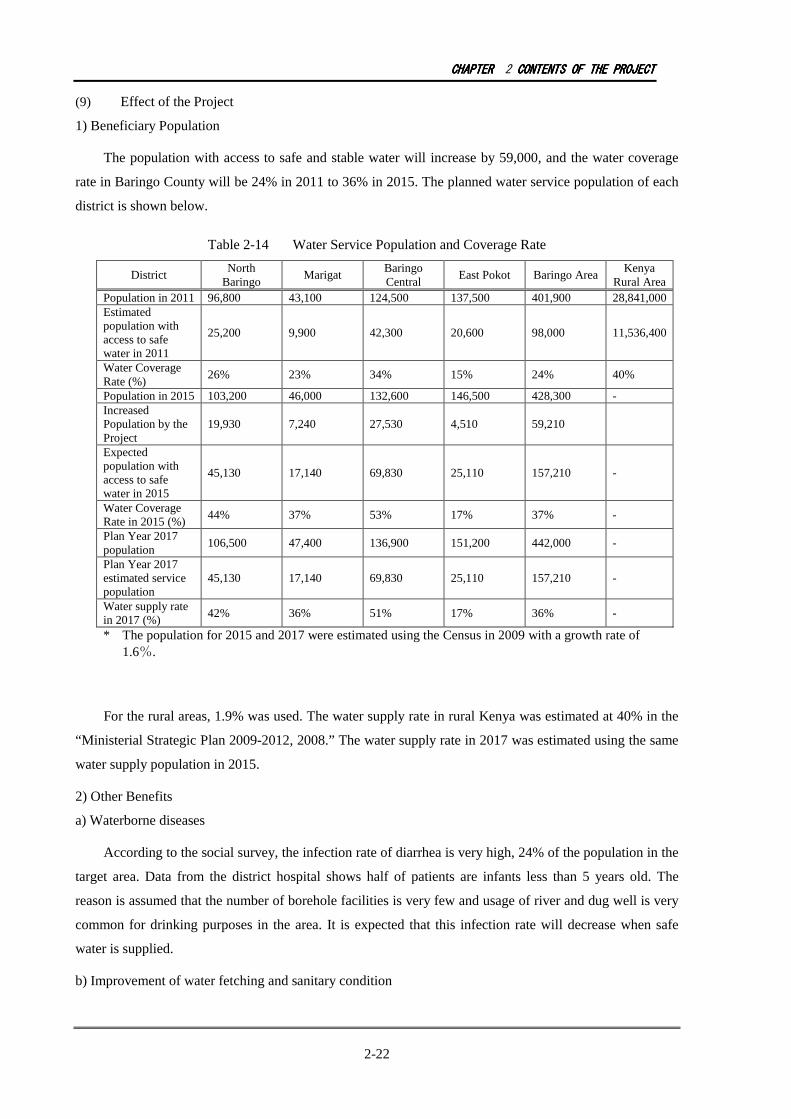
CHAPTERCHAPTERCHAPTERCHAPTER 2 CONTENTSCONTENTSCONTENTSCONTENTS OFOFOFOF THETHETHETHE PROJECTPROJECTPROJECTPROJECT
2-22
(9) Effect of the Project
1) Beneficiary Population
The population with access to safe and stable water will increase by 59,000, and the water coverage
rate in Baringo County will be 24% in 2011 to 36% in 2015. The planned water service population of each
district is shown below.
Table 2-14 Water Service Population and Coverage Rate
District North
Baringo Marigat
Baringo Central
East Pokot Baringo Area Kenya
Rural Area Population in 2011 96,800 43,100 124,500 137,500 401,900 28,841,000 Estimated population with access to safe water in 2011
25,200 9,900 42,300 20,600 98,000 11,536,400
Water Coverage Rate (%)
26% 23% 34% 15% 24% 40%
Population in 2015 103,200 46,000 132,600 146,500 428,300 - Increased Population by the Project
19,930 7,240 27,530 4,510 59,210
Expected population with access to safe water in 2015
45,130 17,140 69,830 25,110 157,210 -
Water Coverage Rate in 2015 (%)
44% 37% 53% 17% 37% -
Plan Year 2017 population
106,500 47,400 136,900 151,200 442,000 -
Plan Year 2017 estimated service population
45,130 17,140 69,830 25,110 157,210 -
Water supply rate in 2017 (%)
42% 36% 51% 17% 36% -
* The population for 2015 and 2017 were estimated using the Census in 2009 with a growth rate of 1.6%.
For the rural areas, 1.9% was used. The water supply rate in rural Kenya was estimated at 40% in the
“Ministerial Strategic Plan 2009-2012, 2008.” The water supply rate in 2017 was estimated using the same
water supply population in 2015.
2) Other Benefits
a) Waterborne diseases
According to the social survey, the infection rate of diarrhea is very high, 24% of the population in the
target area. Data from the district hospital shows half of patients are infants less than 5 years old. The
reason is assumed that the number of borehole facilities is very few and usage of river and dug well is very
common for drinking purposes in the area. It is expected that this infection rate will decrease when safe
water is supplied.
b) Improvement of water fetching and sanitary condition
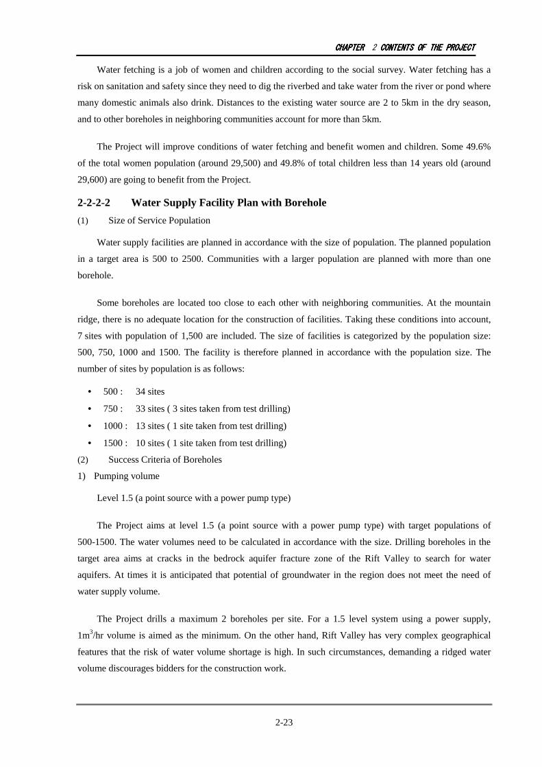
CHAPTERCHAPTERCHAPTERCHAPTER 2 CONTENTSCONTENTSCONTENTSCONTENTS OFOFOFOF THETHETHETHE PROJECTPROJECTPROJECTPROJECT
2-23
Water fetching is a job of women and children according to the social survey. Water fetching has a
risk on sanitation and safety since they need to dig the riverbed and take water from the river or pond where
many domestic animals also drink. Distances to the existing water source are 2 to 5km in the dry season,
and to other boreholes in neighboring communities account for more than 5km.
The Project will improve conditions of water fetching and benefit women and children. Some 49.6%
of the total women population (around 29,500) and 49.8% of total children less than 14 years old (around
29,600) are going to benefit from the Project.
2-2-2-2 Water Supply Facility Plan with Borehole
(1) Size of Service Population
Water supply facilities are planned in accordance with the size of population. The planned population
in a target area is 500 to 2500. Communities with a larger population are planned with more than one
borehole.
Some boreholes are located too close to each other with neighboring communities. At the mountain
ridge, there is no adequate location for the construction of facilities. Taking these conditions into account,
7 sites with population of 1,500 are included. The size of facilities is categorized by the population size:
500, 750, 1000 and 1500. The facility is therefore planned in accordance with the population size. The
number of sites by population is as follows:
• 500 : 34 sites
• 750 : 33 sites ( 3 sites taken from test drilling)
• 1000 : 13 sites ( 1 site taken from test drilling)
• 1500 : 10 sites ( 1 site taken from test drilling)
(2) Success Criteria of Boreholes
1) Pumping volume
Level 1.5 (a point source with a power pump type)
The Project aims at level 1.5 (a point source with a power pump type) with target populations of
500-1500. The water volumes need to be calculated in accordance with the size. Drilling boreholes in the
target area aims at cracks in the bedrock aquifer fracture zone of the Rift Valley to search for water
aquifers. At times it is anticipated that potential of groundwater in the region does not meet the need of
water supply volume.
The Project drills a maximum 2 boreholes per site. For a 1.5 level system using a power supply,
1m3/hr volume is aimed as the minimum. On the other hand, Rift Valley has very complex geographical
features that the risk of water volume shortage is high. In such circumstances, demanding a ridged water
volume discourages bidders for the construction work.

CHAPTERCHAPTERCHAPTERCHAPTER 2 CONTENTSCONTENTSCONTENTSCONTENTS OFOFOFOF THETHETHETHE PROJECTPROJECTPROJECTPROJECT
2-24
In case of commercial power supply and generator, it is possible to prolong operation hours. In this
case, if the yields are 70-60% of the planned volume, a longer hours of operation can cover the daily
planned water supply volume.
In case of solar system, the standard operation hours are set during the rainy season where solar
radiation is minimal. However, more than 5.5 hours of solar radiation can be expected at times. Also,
during the rainy season there are other water sources to meet the daily needs and the usage of water supply
facilities may become less. Therefore, it is possible to set 80-90% of the planned water volume as a
success.
For the sites with high priority, the success criterion is set lower than the first drilling to secure the
success of borehole. The minimum of 1m3/hr is secured and, in addition, the following criteria are set:
First drilling: 60-90% of planned water supply volume / hr, depending on topographic and geological
conditions.
Second drilling: 60% of planned water supply volume / hr, and 1m3/hr or more
The systems with commercial power supply and generator operate from 8 hours/day to as long as
12 hours/day; therefore, 60-70% of the planned water supply volume/hr is regarded as acceptable. The solar
system on the other hand, can operate 10-20% longer during the dry season, and during the rainy season the
rainwater can be used for the daily needs.
The successfully drilled boreholes in the preparatory study were maintained safely by Kenya until the
Project installed pumps and power facilities. The failed boreholes were filled back and the boreholes with
insufficient water quantity were handed over to Kenya.
2) Water Quality
The Kenyan water quality standards manual serves as reference. Water quality that do not meet the
standards is a failure and withdrawn.
The water supply manual indicates the criterion for fluoride, 1.5mg/L. In Kenya there is another
guideline known as “Drinking Water Quality and Effluent Monitoring Guideline,” in which fluoride level is
set at 1.5mg/L with the remark “in exceptional cases due to regional and climate restrictions, 3mg/L may be
applied.”

CHAPTERCHAPTERCHAPTERCHAPTER 2 CONTENTSCONTENTSCONTENTSCONTENTS OFOFOFOF THETHETHETHE PROJECTPROJECTPROJECTPROJECT
2-25
Table 2-15 Comparison of Kenya and WHO Water Quality Standards
Water Quality Items Unit Kenya Standard WHO Standards
(2004)
Arsenic mg/L 0.05 0.01 Fluoride mg/L 3.0 (1.5) 1.5 Manganese mg/L 0.5 0.4 Fe mg/L 1.0 0.3 (1984) Total Dissolved Substances
mg/L 1500 1000 (1984)
Note: Items in parenthesis have no adversary health effect so that no indication was made after the 2004 version.
(3) Outline of Borehole Construction
The drilling depths are set at 100m, 150m, 200m and 250m depending on the results of electrical
exploration and geological data, as well as information on existing boreholes. Borehole depths and the
number of drillings are shown in Table 2-16.
Table 2-16 Borehole Depths and Number of Drillings by District
Borehole Depths District
50m 100m 150m 200m 250m Sum
North Baringo
0 0 15 6 7 30
Central Baringo
0 5(2) 17 17(1) 3 38
Marigat 0 7 5 0 2 15 East Pokot 0 1 10(2) 1 0 7 Totak 0 12(2) 47(2) 23(1) 13 90(5) Note: There were 85 drillings made in total during the construction stage, including
5 successful test drillings in the preparatory study
The drilling method is DHT (Down the Hole Hammer), and pipe diameter is 6-inch steel casing. The
major specifications for drilling are as elaborated below.
1) Casing and screen
Six (6) inch steel casing and screen are employed as the standard. The steel casing and screen are 6m.
A slit is made on the casing to make a screen. The width of slit is approx. 2mm, mouth opening rate is 4%
and more. Parts are connected by welding.
2) Drilling diameter
Drilling diameter is 12 inches from 0 to 12m. Thereafter, the diameter is changed to 10 inches until the
planned depth.

CHAPTERCHAPTERCHAPTERCHAPTER 2 CONTENTSCONTENTSCONTENTSCONTENTS OFOFOFOF THETHETHETHE PROJECTPROJECTPROJECTPROJECT
2-26
3) Gravel filling, cementing
Products for gravel filling materials are available in Kenya. Size 2.5 to 5mm is used for caliber.
Cementing is done after insertion of borehole casing and gravel filling. The 12 inch drilling hole is
cemented until the ground level to protect the borehole from surface pollutants.
4) Pumping test
Pumping test is conducted after insertion of casing. A pump is installed for pumping test using
temporal generator to conduct a step draw-down test, continuous pumping test and water level recovery
test.
- Step draw down test (1hr/step * 5 steps)
- Continuous test (more than 18 hrs)
- Recovery test (more than 6 hrs)
5) Water quality test
Water samples are taken at the pumping test stage to examine water quality. The water sample is sent
to a laboratory in Nakuru or Nairobi where reagents stock and equipment are easily accessible.
2-2-2-3 Water Facility Superstructure
(1) Selection of water supply facility types
1) Types of pumping system
a) Solar Pump
Two types of solar pumping system (DC or AC) are the options. DC type without inverter was
observed in the target area during the preparatory study, and reports have shown that breakdowns were
frequent with the inverter. From the maintenance perspective, DC type is preferable in the area. The criteria
for selection of solar pumping system depend on the pumping volume and groundwater level. In the target
area, lowlands without commercial power supply are the candidate sites for solar pumping system. At
highlands, this system is not appropriate due to natural conditions such as a large annual precipitation
volume.
b) Commercial power supply and submersible water pump
Availability of high-voltage power lines (3 phases, more than 400V) is a precondition to use this
system. From the operation and maintenance point of view, this type is the most appropriate for the target
areas.
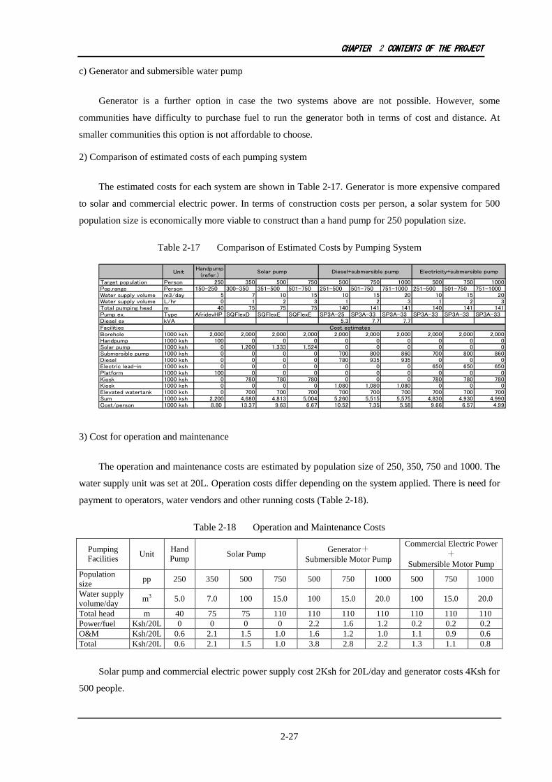
CHAPTERCHAPTERCHAPTERCHAPTER 2 CONTENTSCONTENTSCONTENTSCONTENTS OFOFOFOF THETHETHETHE PROJECTPROJECTPROJECTPROJECT
2-27
c) Generator and submersible water pump
Generator is a further option in case the two systems above are not possible. However, some
communities have difficulty to purchase fuel to run the generator both in terms of cost and distance. At
smaller communities this option is not affordable to choose.
2) Comparison of estimated costs of each pumping system
The estimated costs for each system are shown in Table 2-17. Generator is more expensive compared
to solar and commercial electric power. In terms of construction costs per person, a solar system for 500
population size is economically more viable to construct than a hand pump for 250 population size.
Table 2-17 Comparison of Estimated Costs by Pumping System
Unit
Handpump
(refer.)
Target population Person 250 350 500 750 500 750 1000 500 750 1000
Pop.range Person 150-250 300-350 351-500 501-750 251-500 501-750 751-1000 251-500 501-750 751-1000
Water supply volume m3/day 5 7 10 15 10 15 20 10 15 20
Water supply volume L/hr 0 1 2 3 1 2 3 1 2 3
Total pumping head m 40 75 75 75 140 141 141 140 141 141
Pump ex. Type AfridevHP SQFlexD SQFlexE SQFlexE SP3A-25 SP3A-33 SP3A-33 SP3A-33 SP3A-33 SP3A-33
Diesel ex kVA 5.3 7.7 7.7
Facilities
Borehole 1000 ksh 2,000 2,000 2,000 2,000 2,000 2,000 2,000 2,000 2,000 2,000
Handpump 1000 ksh 100 0 0 0 0 0 0 0 0 0
Solar pump 1000 ksh 0 1,200 1,333 1,524 0 0 0 0 0 0
Submersible pump 1000 ksh 0 0 0 0 700 800 860 700 800 860
Diesel 1000 ksh 0 0 0 0 780 935 935 0 0 0
Electric lead-in 1000 ksh 0 0 0 0 0 0 0 650 650 650
Platform 1000 ksh 100 0 0 0 0 0 0 0 0 0
Kiosk 1000 ksh 0 780 780 780 0 0 0 780 780 780
Kiosk 1000 ksh 0 0 0 0 1,080 1,080 1,080 0 0 0
Elevated watertank 1000 ksh 0 700 700 700 700 700 700 700 700 700
Sum 1000 ksh 2,200 4,680 4,813 5,004 5,260 5,515 5,575 4,830 4,930 4,990
Cost/person 1000 ksh 8.80 13.37 9.63 6.67 10.52 7.35 5.58 9.66 6.57 4.99
Solar pump Diesel+submersible pump Electricity+submersible pump
Cost estimates
3) Cost for operation and maintenance
The operation and maintenance costs are estimated by population size of 250, 350, 750 and 1000. The
water supply unit was set at 20L. Operation costs differ depending on the system applied. There is need for
payment to operators, water vendors and other running costs (Table 2-18).
Table 2-18 Operation and Maintenance Costs
Pumping Facilities
Unit Hand Pump
Solar Pump Generator+
Submersible Motor Pump
Commercial Electric Power+
Submersible Motor Pump Population size
pp 250 350 500 750 500 750 1000 500 750 1000
Water supply volume/day
m3 5.0 7.0 100 15.0 100 15.0 20.0 100 15.0 20.0
Total head m 40 75 75 110 110 110 110 110 110 110 Power/fuel Ksh/20L 0 0 0 0 2.2 1.6 1.2 0.2 0.2 0.2 O&M Ksh/20L 0.6 2.1 1.5 1.0 1.6 1.2 1.0 1.1 0.9 0.6 Total Ksh/20L 0.6 2.1 1.5 1.0 3.8 2.8 2.2 1.3 1.1 0.8
Solar pump and commercial electric power supply cost 2Ksh for 20L/day and generator costs 4Ksh for
500 people.

CHAPTERCHAPTERCHAPTERCHAPTER 2 CONTENTSCONTENTSCONTENTSCONTENTS OFOFOFOF THETHETHETHE PROJECTPROJECTPROJECTPROJECT
2-28
4) Comparison of Pumps
Table 2-19 Comparison of Pumps
Pumping system Advantage Disadvantage
Solar pump
• Available without power distribution lines
• Natural power usage • No cost incurred for power • O&M is easy
• Depends on weather and seasonal solar power
• General pumps have restricted capacity by water level and water volume
Commercial power supply + submersible water pump
• Comparatively less cost for power • O&M is needed only for pump, thus
easy.
• Power distribution lines are available only at certain communities
• Installation takes longer time and transmission and distribution lines need additional costs
Generator + submersible water pump
• Available without power distribution lines
• Need to buy and transport fuel • O&M costs relatively high • Construction costs relatively high
Hand pump • Easier for operation and maintenance
by communities • No need for power
• Need to have spare parts sellers and knowledge to change parts
• Not usable with a deep water level
5) Review of solar pumping system
Based on the discussions above, power pumping facilities were carefully selected for each target
community. Selection was carried out according to the flow in Figure 3-6 considering assessment of
potential groundwater development. Commercial power is used in case it is available, and if it is difficult, a
solar pump is deployed.
The amount of solar radiation is not measured in the target area. Data from the NASA satellite system
is summarized in Table 2-20. The data are an average of 22 years (1983-2004), which is calculated as a
representative value by 1 mesh of latitude x longitude. In the target area, there is enough amount of solar
radiation (kWh/m2/day). In general, solar pumping system is appropriate for this area.
Table 2-20 Monthly Average Solar Radiation in Northern Kenya
Month Jan Feb Mar Apr May Jun Jul Aug Sep Oct Nov Dec Average
Average 6.24 6.71 6.59 5.94 5.68 5.33 5.09 5.33 6.19 5.97 5.62 6.05 5.89
Source: JICA Rural Electrification by Renewable Energy Modeling Project
Regional characteristics need to be taken into account to deploy a solar pumping system. The data
shown in Table 2-20 are representative values of both high and lowlands. In reality, highlands receive more
rain and solar radiation is less than at lowlands.
The weather station in the target area has only the data of precipitation. Nakuru is located outside of
the Project area, but nearby, thus taken as an indicative data set to evaluate. Monthly average solar
radiation hours in Nakuru were 5.8-9.4 hours, with an average of 8 hours.
CHAPTERCHAPTERCHAPTERCHAPTER 2 CONTENTSCONTENTSCONTENTSCONTENTS OFOFOFOF THETHETHETHE PROJECTPROJECTPROJECTPROJECT
2-29
Figure 2-4 Monthly Average Solar Radiation
The annual precipitation in Nakuru is 970mm. During 1997-2009, the duration of solar radiation was
4-6 hours in April and November with precipitation of 150-200mm per month. In highlands and lowlands
in the target area, they receive 1,300-1,400mm of rainfall precipitation per year, while 200-250mm in
April-May and July-August. The condition of solar radiation may be more severe. Under such conditions,
8 hours are counted for a submersible pump and 5.5 hours for a solar pump.
The following equation shows the output of the pumps.
P= 0.163・Q・H/ η
P: motor output (kW)
Q: The amount of the pump discharge
H: Total pump head
η: Pump efficiency (%)
The range of use of solar pumps is assessed, based on the pump performance curves that are locally
available, using pumping quantity and the total pump head (elevation difference between the reservoir
water level and water level during the pump operation) (Figure 2-5). Solar pump can be adjustable with
different numbers of solar panel. With the maximum output of 1400W, 130m of pump head and 2.3㎥/h is
reachable. Selection is made using these formulas (Figure 2-6).

CHAPTERCHAPTERCHAPTERCHAPTER 2 CONTENTSCONTENTSCONTENTSCONTENTS OFOFOFOF THETHETHETHE PROJECTPROJECTPROJECTPROJECT
2-30
HWL
Dynamic W.
level
Static W.
level
Water level during
operation
Total Pump
head
P P P P Output Output Output Output (W)
500 1000
120m
Performance range
for pump type:SQF
2.5-2
Solar pump
performance curve
1400
100m
130m
80m
40m20m10m
60m
5m
110m
HHHH Total pump
head (m)
Figure 2-5 Total Pump Head Concept Figure 2-6 Performance Curve of Solar Pump
6) Selection of pumping system
Not
possible
Target sites
Commercial power
grid+
submersible pump
商用電力
Solar pumpSolar system
Not
possible
Generator, population
size:750 for O&M
Generator+
submersible motor
pump
Commercial power
grid:transmission
600m or less
37Sites
43 Sites
10 Sites
Transmission lines exist,
operation 8 hours for
pumping to secure water
volume
10 sites
90
sites
53 sites
Operation 5.5 hours based
on estimated ground water
level, estimated yield to
secure water volume
Population size 750 or more,
transmission lines, operation 8
hours for pumping to secure
water volume
Possible
Possible
Possible
37 sites
43 sites
10 sites
0 site
Figure 2-7 Selection Logics for Pump Types
Selection criteria are as follows:
a) Commercial Electricity
• Electricity grid is located within 600m of the water source
• A plan is made for 8 operation hours
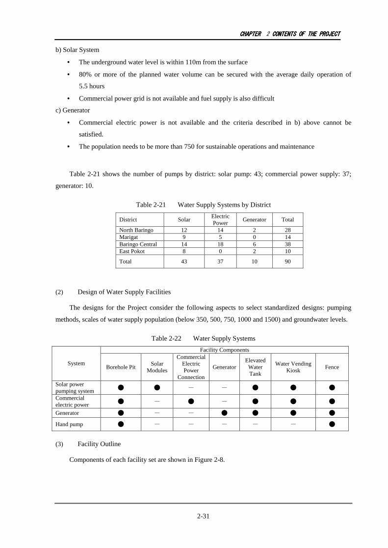
CHAPTERCHAPTERCHAPTERCHAPTER 2 CONTENTSCONTENTSCONTENTSCONTENTS OFOFOFOF THETHETHETHE PROJECTPROJECTPROJECTPROJECT
2-31
b) Solar System
• The underground water level is within 110m from the surface
• 80% or more of the planned water volume can be secured with the average daily operation of
5.5 hours
• Commercial power grid is not available and fuel supply is also difficult
c) Generator
• Commercial electric power is not available and the criteria described in b) above cannot be
satisfied.
• The population needs to be more than 750 for sustainable operations and maintenance
Table 2-21 shows the number of pumps by district: solar pump: 43; commercial power supply: 37;
generator: 10.
Table 2-21 Water Supply Systems by District
District Solar Electric Power
Generator Total
North Baringo 12 14 2 28 Marigat 9 5 0 14 Baringo Central 14 18 6 38 East Pokot 8 0 2 10
Total 43 37 10 90
(2) Design of Water Supply Facilities
The designs for the Project consider the following aspects to select standardized designs: pumping
methods, scales of water supply population (below 350, 500, 750, 1000 and 1500) and groundwater levels.
Table 2-22 Water Supply Systems
Facility Components
System Borehole Pit
Solar Modules
Commercial Electric Power
Connection
Generator Elevated Water Tank
Water Vending Kiosk
Fence
Solar power pumping system ● ● - - ● ● ●
Commercial electric power ● - ● - ● ● ●
Generator ● - - ● ● ● ●
Hand pump ● - - - - - ●
(3) Facility Outline
Components of each facility set are shown in Figure 2-8.

CHAPTERCHAPTERCHAPTERCHAPTER 2 CONTENTSCONTENTSCONTENTSCONTENTS OFOFOFOF THETHETHETHE PROJECTPROJECTPROJECTPROJECT
2-32
Figure 2-8 Facility Outline
Power supply facilities having different specifications of scale are shown in the table below. The
overview of each facility is outlined in the following paragraphs.
Kiosk
Borehole, pit
Solar Panel System
Elevated
Water tank
Borehole, pit
Kiosk (Generator) Elevated
Water Tank
Generator
T
Commercial Electricity
Supply
Borehole, pit
Kiosk
Transmission lines, Transformer
Elevated
Water tank
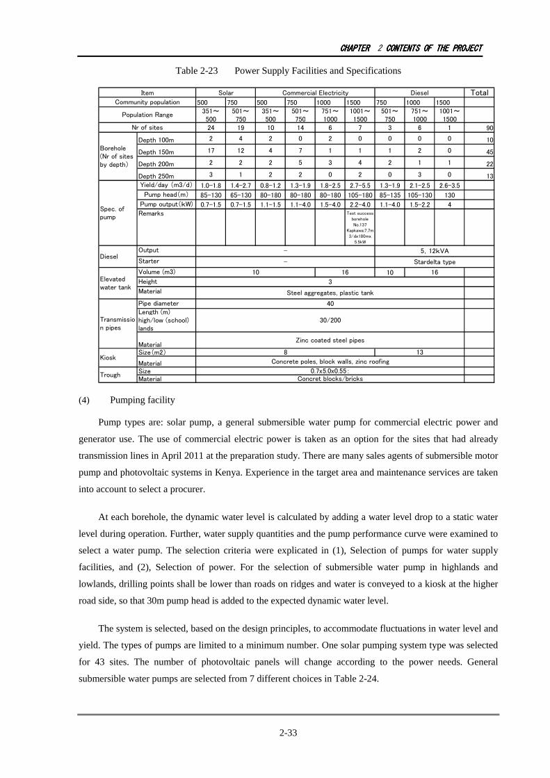
CHAPTERCHAPTERCHAPTERCHAPTER 2 CONTENTSCONTENTSCONTENTSCONTENTS OFOFOFOF THETHETHETHE PROJECTPROJECTPROJECTPROJECT
2-33
Table 2-23 Power Supply Facilities and Specifications
Total
500 750 500 750 1000 1500 750 1000 1500
351~
500
501~
750
351~
500
501~
750
751~
1000
1001~
1500
501~
750
751~
1000
1001~
1500
24 19 10 14 6 7 3 6 1 90
Depth 100m2 4 2 0 2 0 0 0 0
10
Depth 150m17 12 4 7 1 1 1 2 0
45
Depth 200m2 2 2 5 3 4 2 1 1
22
Depth 250m3 1 2 2 0 2 0 3 0
13
Yield/day (m3/d) 1.0-1.8 1.4-2.7 0.8-1.2 1.3-1.9 1.8-2.5 2.7-5.5 1.3-1.9 2.1-2.5 2.6-3.5
Pump head(m) 85-130 65-130 80-180 80-180 80-180 105-180 85-135 105-130 130
Pump output(kW) 0.7-1.5 0.7-1.5 1.1-1.5 1.1-4.0 1.5-4.0 2.2-4.0 1.1-4.0 1.5-2.2 4
Remarks Test success
borehole
No.137
Kapkawa:7.7m
3/dx180mx
5.5kW
Output
Starter
Volume (m3) 10
Height
Material
Pipe diameter
Length (m)
high/low (school)
lands
Material
Size(m2)
Material
Size
Material
Item Solar Commercial Electricity Diesel
Community population
Population Range
Nr of sites
Borehole
(Nr of sites
by depth)
Spec. of
pump
Diesel
- 5,12kVA
- Stardelta type
Elevated
water tank
10 16 16
3
Steel aggregates, plastic tank
Transmissio
n pipes
40
30/200
Zinc coated steel pipes
Trough
0.7x5.0x0.55:
Concret blocks/bricks
Kiosk
8 13
Concrete poles, block walls, zinc roofing
(4) Pumping facility
Pump types are: solar pump, a general submersible water pump for commercial electric power and
generator use. The use of commercial electric power is taken as an option for the sites that had already
transmission lines in April 2011 at the preparation study. There are many sales agents of submersible motor
pump and photovoltaic systems in Kenya. Experience in the target area and maintenance services are taken
into account to select a procurer.
At each borehole, the dynamic water level is calculated by adding a water level drop to a static water
level during operation. Further, water supply quantities and the pump performance curve were examined to
select a water pump. The selection criteria were explicated in (1), Selection of pumps for water supply
facilities, and (2), Selection of power. For the selection of submersible water pump in highlands and
lowlands, drilling points shall be lower than roads on ridges and water is conveyed to a kiosk at the higher
road side, so that 30m pump head is added to the expected dynamic water level.
The system is selected, based on the design principles, to accommodate fluctuations in water level and
yield. The types of pumps are limited to a minimum number. One solar pumping system type was selected
for 43 sites. The number of photovoltaic panels will change according to the power needs. General
submersible water pumps are selected from 7 different choices in Table 2-24.

CHAPTERCHAPTERCHAPTERCHAPTER 2 CONTENTSCONTENTSCONTENTSCONTENTS OFOFOFOF THETHETHETHE PROJECTPROJECTPROJECTPROJECT
2-34
Table 2-24 Population Scale, Volume, Pump Head
Total Pump Head (m)
Pumping Quantity (m3/hr)
Quantity (per machine)
Remarks
110 8.0 1 Kapkawa 180 4.0 12 130 2.8 3 155 1.8 12 110 2.2 7 160 1.2 3 110 1.3 9
Total 47
(5) Generator
Generators are installed at 18 sites in total. The starting method is the star-delta type. Two types of
output, 5.5KVA and 10KVA, were selected which are 3 times larger than the output of pumps.
Table 2-25 Population Scale and Pumping
Capacity, Pump Head
Capacity (kVA) Quantity
(machine) Starting method
5.5 1 Star delta 10 9 Star delta
Total 10
(6) Elevated Water Tank
In the target area, tanks in steel, concrete and plastic are commonly found. Steel gets rusty where
leakages occur and eventually become unusable. Concrete types are placed on the ground and have become
obsolete. The use of plastic types has increased in recent years, and for the Project there is a wide range of
selection for various volume needs.
Table 2-26 Water Tanks Summary
Type of Tank Installation Achievement Price Operation and Maintenance Steel Water Tank ○ ○ △
Concrete Water Tank ○ ○ ○
Plastic Water Tank ◎ ◎ ◎
For the Project, elevated plastic tanks fixed on top of steel legs are employed.
The communities that have existing reservoirs are Salawa Hospital (104-1) and Kapkawa (137-1).
Both sites have springs as water source but the springs dry up during the dry season. Salawa
Hospital (104-1) has a reservoir at a higher location than the hospital, which is convenient for use.

CHAPTERCHAPTERCHAPTERCHAPTER 2 CONTENTSCONTENTSCONTENTSCONTENTS OFOFOFOF THETHETHETHE PROJECTPROJECTPROJECTPROJECT
2-35
{Kapkawa (137-1) was successfully drilled during the 2nd preparatory survey.) Many residents have no
water connection, thus the project include connections to existing reservoirs, new tank construction and
kiosk to sell water. Considering the project to be rural water supply, elevated water tank and storage
capacity are set, in accordance with Design Manual, in the range of 50 to 100% of daily water supply. Two
types of capacities of tanks are selected for the project: 10m3 for less than 500 750 users and 16m3 for 750
to 1,500 users. The elevation height is set at 3m to secure enough water pressure for distribution.
Table 2-27 Pumping Capacity and Quantity
Capacity(m3) Quantity Remarks
10 55 16 34
Total 89 1 existing pond is used
(7) Water Vending Kiosk
A water vending kiosk has a water pump control panel inside. An incoming panel is also equipped on
the kiosk for commercial electric power use. A standard floor area of about 8.0m2 (2.3mx 3.5m) is
designed for all sites. If a generator is applied for the system, a generator room (steel net wall, floor area
5.0m2) is annexed outside the kiosk. The number of tap is a flat 4 to improve the efficiency of sale of water.
(8) Water Pipe
In the middle and high lands, borehole positions selected are lower than the ridge on which roads run.
Therefore, water pipes are placed to send water from the borehole to a higher located kiosk. Transmission
distance is on average 200m according to the preparatory survey result.
In the lowlands, in principle the boreholes and water vending kiosk are located at the same premises,
thus the length of the pipe is 30m. In case of schools, a kiosk needs to be placed outside of the school
premises so as to have a 200m transmission pipe. The discharge of the pipes is calculated with the
Hezen-Williams equation, as follows:
H=10.666 ×C-1.85 × D-4.87 × Q1.85 × L
H: Friction Head Loss (m)
C: Coefficient of velocity
D: Pipe diameter (m)
Q: Water discharge quantity (m3/sec)
L: Length (m)

CHAPTERCHAPTERCHAPTERCHAPTER 2 CONTENTSCONTENTSCONTENTSCONTENTS OFOFOFOF THETHETHETHE PROJECTPROJECTPROJECTPROJECT
2-36
The diameter of 40mm is appropriate considering the friction head loss not to be too large with the
water discharge of 1 m3/sec to 3 m3/sec. The Project uses the zinc galvanized steel pipes placed on the
ground since the area is rocky at some locations.
Table 2-28 Overview of Water Transmission Pipes
Diameter Material Length Remarks
High, middle-lands, school
40mm Galvanized steel pipe
Average 200m Borehole is lower than kiosk. Schools in lowland
Lowland Ibid. Ibid. Average 30m Borehole, elevated water tank and kiosk located in the same premise
(9) Trough for livestock
In the target area, most communities keep goats, sheep and other livestock. If there is sufficient water
supply, water is given to livestocks. A trough is constructed outside the fence for reasons of hygiene.
Troughs are made of concrete blocks, brick, or mortar with a standard size of 0.55m x 0.7m x 5.0m.
(10) Fence
Fences are necessary to prevent intrusion of wild animals and theft. The area is rocky so that the
installation needs professional hands with drilling equipment. Fence is a steel pump with entanglement.
(11) Success Criteria and Installation of Facilities
The success criteria of borehole and installation of facilities are determined as shown in the following
table.

CHAPTERCHAPTERCHAPTERCHAPTER 2 CONTENTSCONTENTSCONTENTSCONTENTS OFOFOFOF THETHETHETHE PROJECTPROJECTPROJECTPROJECT
2-37
Table 2-29 Success Criteria and Installation of Facilities
Population Size
First Drilling (Trial) Second Trial Remarks
1500
Secured more than 60-90% of design water supply and more than 1m3/hr: Boreholes deemed successful, to establish the initial design of water supply facilities.
Secured less than 90% of design water supply�2nd drilling trial
2nd try at the same site: Secured more than 60% of design water supply and more than 1 m3/hr: boreholes deemed successful, to establish the initial design of water supply facilities.
For 1500 population size, during the detailed design, 9 sites are drilled and the facility designs determined except 1 site already successful from the preparatory study.
1000
Did not satisfy the above conditions�2nd drilling trial
2nd try at the same site: Secured more than 60% of design water supply and more than 1 m3/hr: boreholes deemed successful, to establish the initial design of water supply facilities.
Did not satisfy the above conditions�2nd drilling trial
For 1000 population size, during the detailed design, 1 site is drilled and the facility designs determined. 1 site already successful from the preparatory study, remaining is 9 sites. Initially designed pumps are used, in case of commercial power, operating hours are extended. If the number of photovoltaic panels is in surplus, the rest is kept by DWO.
750 ditto ditto ditto
500 ditto ditto ditto

CHAPTERCHAPTERCHAPTERCHAPTER 2 BACKGROUND OF THE PROJECTCONTENTSCONTENTSCONTENTSCONTENTS OFOFOFOF THTHTHTHEEEE PROJECTPROJECTPROJECTPROJECT
2-38
Table 2-30 Water Supply System Analysis Population
2011 Day Sch. Boarding
Pop.
Convert
2017 (ref.) Diam. Velocity Volume H
(Pers.) (Pers.) (Pers.) (Pers.) (Pers.)
Corrected
(pers.)
(Pers.) (L/d・Pers)
2015
(m
3
/d)
(m) (m) (m) (m) (m3/h) (mm) (m/sec) (m3) (m)
1 Katiborok Baringo North 450 520 30 510510510510 750750750750 530 20 10.2 31 3 3Phases 50 150 79 70 55.3 40 75 85 16.0 40 0.3 H 10 3 1 DD掘さく
2 Konoo Baringo North 450 252 3 480480480480 500500500500 500 20 9.6 64 2 3Phases 50 150 79 70 55.3 40 75 85 5.0 40 0.3 H 10 3 1
3 Kormor Baringo North 310 350 20 350350350350 500500500500 360 20 7.0 65 2 Solar 150 79 70 55.3 40 75 105 5.0 40 0.3 H 10 3 1
5 Kibuliak Baringo North 670 772 44 760760760760 1,0001,0001,0001,000 790 20 15.2 32 4 3Phases 30 150 79 70 55.3 40 75 85 5.0 40 0.4 H 16 3 1
6 Kapnarok Baringo North 360 360 18 400400400400 500500500500 420 20 8.0 11 2 Solar 150 87 86 74.8 40 75 105 5.0 40 0.3 H 10 3 1
7 Chemondoi Baringo North 860 567 14 930930930930 1,0001,0001,0001,000 960 20 18.6 33 4 Generator 250250250250 70 80 56 60 100 130 6.0 40 0.5 H 16 3 1
10 Moigutwo Baringo North 340 740 57 420420420420 500500500500 440 20 8.4 66 2 Solar 200 70 80 56 60 100 130 6.0 40 0.3 H 10 3 1
12 Ayatia Baringo North 340 300 13 380380380380 500500500500 390 20 7.6 67 2 Solar 150 79 70 55.3 40 75 105 5.0 40 0.3 H 10 3 1
13 Marigut Baringo North 430 463 25 480480480480 500500500500 500 20 9.6 68 2 3Phases 50 150 79 70 55.3 30 50 80 5.0 40 0.3 H 10 3 1
16 Kapkombe Baringo North 1,000 280 1,0701,0701,0701,070 1,0001,0001,0001,000 1,100 20 21.4 12 5 3Phases 50 200 70 80 56 60 100 130 6.0 40 0.6 H 16 3 1 BH Drilling in DD
28 Kolongotwo Baringo North 420 450450450450 500500500500 460 20 9.0 69 2 Solar 150 70 85 59.5 40 75 105 4.0 40 0.4 H 10 3 1
29 Koibaware Baringo North 310 1,090 94 430430430430 500500500500 440 20 8.6 70 2 Solar 150 70 85 59.5 40 75 105 4.0 40 0.3 H 10 3 1
31 Kipchemoi Baringo North 350 600 43 370370370370 500500500500 380 20 7.4 71 2 Solar 150 70 85 59.5 50 75 85 4.0 40 0.3 H 10 3 1
32 Kapturo Baringo North 460 600 37 530530530530 750750750750 550 20 10.6 34 3 Solar 150 68 85 57.8 50 75 105 2.5 40 0.4 H 10 3 1
33 Chepkesin Baringo North 400 400 20 450450450450 500500500500 460 20 9.0 72 2 Solar 150 70 85 59.5 50 75 105 4.0 40 0.4 H 10 3 1
36.1 Barwessa-1 Baringo North 400 630 100 143 580580580580 750750750750 600 20 11.6 35 3 3Phases 100 150 79 70 55.3 40 75 105 5.0 40 0.3 H 10 3 1
36.2 Barwessa-2 Baringo North 400 430430430430 500500500500 440 20 8.6 73 2 Solar 150 79 70 55.3 40 75 105 5.0 40 0.3 H 10 3 1
38 Likwon Baringo North 470 340 120 131 640640640640 750750750750 660 20 12.8 2 3 Solar 150 87 85 74 40 75 105 5.0 40 0.5 H 16 3 1
39 Seremwo Baringo North 400 220 2 430430430430 500500500500 440 20 8.6 74 2 Solar 250250250250 70 80 56 60 100 130 3.0 40 0.3 H 10 3 1
40 Kapkirwok Baringo North 600 350 570 575 1,2501,2501,2501,250 1,5001,5001,5001,500 1,290 20 25.0 13 5 3Phases 200 200 70 80 56 60 100 130 4.0 40 0.7 H 16 3 1 BH Drilling in DD
43.1 Kaptere1 Baringo North 160 1,050 420 517 720720720720 750750750750 740 20 14.4 36 3 3Phases 150 250250250250 70 80 56 80 125 155 4.0 40 0.4 H 16 3 1
43.2 Kaptere2 Baringo North 640 680680680680 750750750750 700 20 13.6 37 3 3Phases 150 250250250250 70 80 56 80 125 155 4.0 40 0.4 H 16 3 1
45 Tiriondonin Baringo North 450 560 450 484 990990990990 1,0001,0001,0001,000 1,030 20 19.8 14 4 Generator 250250250250 70 80 56 60 100 130 6.0 40 0.5 H 16 3 1 BH Drilling in DD
46 Kaptum Baringo North 620 1,130 450 532 1,2301,2301,2301,230 1,5001,5001,5001,500 1,270 20 24.6 15 5 3Phases 200 200 70 80 56 60 100 130 6.0 40 0.7 H 16 3 1 BH Drilling in DD
47.1 Ossen Forest station1 Baringo North 134 1,240 450 567 750750750750 750750750750 770 20 15.0 38 3 3Phases 200 200 70 80 56 100 150 180 4.0 40 0.4 H 16 3 1
47.2 Ossen Forest station2 Baringo North 757 810810810810 1,0001,0001,0001,000 830 20 16.2 39 4 3Phases 200 200 70 80 56 100 150 180 4.0 40 0.4 H 16 3 1
49 Kureschun Baringo North 1,500 280 1,6001,6001,6001,600 1,5001,5001,5001,500 1,650 20 32.0 16 5 3Phases 100 250250250250 70 80 56 100 150 180 4.0 40 0.9 H 16 3 1 BH Drilling in DD
50 Kipkokom Baringo North 1,000 400 1,0701,0701,0701,070 1,5001,5001,5001,500 1,100 20 21.4 17 5 3Phases 300 250250250250 70 80 56 100 150 180 4.0 40 0.6 H 16 3 1 BH Drilling in DD
51 Kamagonge Marigat 450 450 450 960960960960 1,0001,0001,0001,000 990 15 14.4 18 4 3Phases 300 100 85 76 64.6 50 75 105 4.0 40 0.4 H 16 3 1 DD掘さく
53 Kapsamson Marigat 450 640 42 520520520520 750750750750 540 15 7.8 19 3 Solar 100 85 76 64.6 50 75 105 4.0 40 0.3 H 10 3 1
56 Kamimba Marigat 450 81 480480480480 500500500500 490 15 7.2 40 2 3Phases 200 100 85 76 64.6 50 75 85 4.0 40 0.2 H 10 3 1
58 Catholic Marigat 390 296 10 430430430430 500500500500 440 15 6.5 41 2 3Phases 200 100 85 76 64.6 50 75 105 4.0 40 0.2 H 10 3 1
60 Ndambul Marigat 380 770 58 470470470470 500500500500 480 15 7.1 42 2 Solar 100 85 76 64.6 50 75 105 4.0 40 0.3 H 10 3 1
64 Longiron Marigat 490 224 520520520520 750750750750 540 15 7.8 20 3 Solar 100 80 75 60 50 75 85 2.0 40 0.3 H 10 3 1
65 Marti Marigat 460 612 38 530530530530 750750750750 550 15 8.08.08.08.0 21 3 Solar 100 80 75 60 50 75 85858585 2.0 40 0.3 H 10 3 1
69 Kapkechii Marigat 315 395 24 360360360360 500500500500 370 15 5.4 75 2 Solar 150 70 85 59.5 50 75 105 4.0 40 0.2 H 10 3 1
72 Kimalel Hospital Marigat 380 400400400400 500500500500 420 15 6.0 76 2 3Phases 100 250250250250 70 85 59.5 50 75 105 2.0 40 0.2 H 10 15 1
74 Lokoiwopsonchun Marigat 370 200 2 400400400400 500500500500 410 15 6.0 77 2 3Phases 100 150 70 85 59.5 50 75 105 2.0 40 0.2 H 10 3 1
75 Kinyach Marigat 320 356 20 360360360360 500500500500 370 15 5.4 78 2 Solar 250250250250 70 85 59.5 50 75 105 2.0 40 0.2 H 10 3 1
77 Tirng'ongwonin Marigat 350 125 370370370370 500500500500 380 15 5.6 79 2 Solar 150 65 85 55.3 50 75 105 2.0 40 0.2 H 10 3 1
78 Kibingor Marigat 450 240 2 480480480480 500500500500 500 15 7.2 80 2 Solar 150 65 85 55.3 50 75 105 2.0 40 0.3 H 10 3 1
81 Kabusa Marigat 600 279 640640640640 750750750750 660 15 9.6 43 3 Solar 150 70 85 59.5 50 75 105 4.0 40 0.4 H 10 3 1
TotalTotalTotalTotal
pumppumppumppump
headheadheadheadNr.
School
DistrictSite Name
Success rateSuccess rateSuccess rateSuccess rate
(%)(%)(%)(%)
Water tank
Genera
tor
room
Type
SizeSizeSizeSize System type
Distance toDistance toDistance toDistance to
power gridpower gridpower gridpower grid
(m)(m)(m)(m)
Water supply population
Planned year 2015Planned year 2015Planned year 2015Planned year 2015 Priorit
y
Day supply
volume
Water
supply
unitRemarksKiosk
BH
depth
Static Dynamic
Defluo
rin
SuccesSuccesSuccesSucces
s rates rates rates rate
(Volum(Volum(Volum(Volum
e)e)e)e)
Yield
estimate
SuccesSuccesSuccesSucces
s rates rates rates rate
(Quality(Quality(Quality(Quality
))))
Trans. Pipe
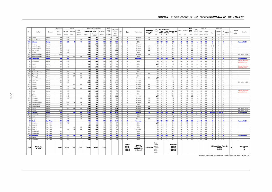
CHAPTERCHAPTERCHAPTERCHAPTER 2 BACKGROUND OF THE PROJECTCONTENTSCONTENTSCONTENTSCONTENTS OFOFOFOF THETHETHETHE PROJECTPROJECTPROJECTPROJECT
2-39
Population
2011 Day Sch. Boarding
Pop.
Convert
2017 (ref.) Diam. Velocity Volume H
(Pers.) (Pers.) (Pers.) (Pers.) (Pers.)
Corrected
(pers.)
(Pers.) (L/d・Pers)
2015
(m
3
/d)
(m) (m) (m) (m) (m3/h) (mm) (m/sec) (m3) (m)
101 Kaptara Baringo 600 288 640640640640 750750750750 660 20 12.8 44 3 3Phases 50 150 79 70 55.3 40 75 105 5.0 40 0.4 H 16 3 1
102 Kipsoit Primary Baringo 500 598 35 570570570570 750750750750 590 20 11.4 45 3 3Phases 50 150 79 70 55.3 40 75 105 5.0 40 0.3 H 10 3 1
103.1103.1103.1103.1 KakwaneKakwaneKakwaneKakwane BaringoBaringoBaringoBaringo 550550550550 128128128128 41414141 41414141 630630630630 750750750750 650650650650 20202020 12.612.612.612.6 3333 3333 SolarSolarSolarSolar 100100100100 100100100100 100100100100 100100100100 40404040 60606060 70707070 5.05.05.05.0 40404040 0.50.50.50.5 HHHH 16161616 3333 1111 Successful BHSuccessful BHSuccessful BHSuccessful BH
103.2 Kakwane Baringo 750 800800800800 1,0001,0001,0001,000 820 20 16.0 4 4 3Phases 100 87 86 74.8 40 75 85 5.0 40 0.4 H 16 3 1
104.1 Salawa Hospital1 Baringo 590 630630630630 750750750750 650 20 12.6 22 3 3Phases 100 150 85 75 63.8 40 75 135 5.0 40 0.3 EX-G 70 1
104.2 Salawa Hospital2 Baringo 590 630630630630 750750750750 650 20 12.6 23 3 3Phases 100 150 85 75 63.8 40 75 135 5.0 40 0.3 H 16 1
106 Eron Primary Baringo 700 210 750750750750 750750750750 770 20 15.015.015.015.0 5 3 3Phases 150150150150 150 87 86 74.8 40 75 105105105105 5.0 40 0.4 H 16 3 1
107 Kimoso Baringo 540 205 580580580580 750750750750 590 20 11.6 24 3 Solar 150 85 75 63.8 50 75 105 5.0 40 0.5 H 10 3 1
109.1 Oinobmoi centre1 Baringo 1,343 1,4301,4301,4301,430 1,5001,5001,5001,500 1,480 20 28.6 6 5 3Phases 200 150 85 75 63.8 40 75 105 5.0 40 0.8 H 16 3 1 BH Drilling in DD
109.2 Oinobmoi centre2 Baringo 562 470 526 560560560560 750750750750 580 20 11.2 25 3 Solar 150 85 75 63.8 40 75 105 5.0 40 0.5 H 10 3 1
110110110110 KapsikoryanKapsikoryanKapsikoryanKapsikoryan BaringoBaringoBaringoBaringo 900900900900 185185185185 960960960960 1,0001,0001,0001,000 990990990990 20202020 19.219.219.219.2 7777 4444 GeneratorGeneratorGeneratorGenerator 150150150150 100100100100 100100100100 100100100100 60606060 90909090 120120120120 2.52.52.52.5 40404040 0.50.50.50.5 HHHH 16161616 3333 1111 Successful BHSuccessful BHSuccessful BHSuccessful BH
111 Kurumbopsoo Baringo 800 240 850850850850 1,0001,0001,0001,000 880 20 17.0 26 4 Solar 150 85 75 63.8 50 75 105 5.0 40 0.6 H 16 3 1
Design 84% of the
planned volume
112 Sironoi Baringo 500 175 530530530530 750750750750 550 20 10.6 46 3 Solar 250250250250 70 80 56 60 100 130 6.0 40 0.4 H 10 3 1
113 Kasitet Baringo 810 240 860860860860 1,0001,0001,0001,000 890 20 17.2 47 4 Solar 150 79 70 55.3 50 75 105 5.0 40 0.6 H 16 3 1
Design 84% of the
planned volume
114 Sichei Baringo 350 370370370370 500500500500 380 20 7.4 81 2 Solar 150 79 70 55.3 50 75 105 5.0 40 0.3 H 10 3 1
119 Chepkero Primary Baringo 450 200 480480480480 500500500500 490 20 9.6 82 2 Solar 150 79 70 55.3 70 100 130 5.0 40 0.4 H 10 3 1
120.1 Mogorwa-1 Baringo 180 138 200 205 410410410410 500500500500 420 20 8.2 83 2 3Phases 300 150 79 70 55.3 50 75 105 2.5 40 0.2 H 10 3 1
120.2 Mogorwa-2 Baringo 180 138 200 205 410410410410 500500500500 420 20 8.2 84 2 Solar 150 79 70 55.3 50 75 105 2.5 40 0.3 H 10 3 1
121 Kisonei Primary Baringo 400 473 27 460460460460 500500500500 470 20 9.2 48 2 3Phases 200 250250250250 80 80 64 60 100 130 5.0 40 0.3 H 10 3 1
122 Ochii Primary Baringo 650 316 690690690690 750750750750 710 20 13.8 27 3 Generator 200 80 80 64 60 100 130 5.0 40 0.4 H 16 3 1
123 Siginwo Baringo 990 190 1,0501,0501,0501,050 1,0001,0001,0001,000 1,090 20 21.0 28 5 Generator 200 70 80 56 60 100 130 6.0 40 0.6 H 16 3 1 BH Drilling in DD
124.1 Tabarin1 Baringo 70 620 620 740740740740 750750750750 760 20 14.8 49 3 3Phases 200 200 70 80 56 60 100 130 6.0 40 0.4 H 16 3 1
124.2 Tabarin2 Baringo 630 212 670670670670 750750750750 690 20 13.4 50 3 Generator 200 200 70 80 56 60 100 130 6.0 40 0.4 H 16 3 1
125 Tuluongoi Baringo 724 350 200 200 980980980980 1,0001,0001,0001,000 1,020 20 19.6 51 4 3Phases 300 200 70 80 56 60 100 130 6.0 40 0.5 H 16 3 1
126 Tebei Baringo 829 400 880880880880 1,0001,0001,0001,000 910 20 17.6 52 4 Solar 150 70 85 59.5 50 75 105 4.0 40 0.6 H 16 3 1
Design 84% of the
planned volume
127 Ilyakat Baringo 376 150 400400400400 500500500500 410 20 8.0 85 2 Solar 150 70 85 59.5 50 75 105 4.0 40 0.3 H 10 3 1
129 Tinomoi Baringo 886 142 940940940940 1,0001,0001,0001,000 970 20 18.818.818.818.8 53 4 Generator 250250250250 65 85 55.3 70 100 130130130130 4.0 40 0.5 H 16 3 1
130.1 Timboiywo1 Baringo 598 689 39 680680680680 750750750750 700 20 13.6 54 3 3Phases 100 200 70 80 56 60 100 130 6.0 40 0.4 H 16 3 1
130.2 Timboiywo2 Baringo 702 750750750750 750750750750 770 20 15.0 55 3 3Phases 100 200 70 80 56 60 100 130 6.0 40 0.4 H 16 3 1
133 Kapchomuswo Sec Baringo 300 1,300 140 255 590590590590 750750750750 610 20 11.8 56 3 3Phases 200 200 70 80 56 60 100 130 6.0 40 0.3 H 10 3 1
134 Kiwanja Ndege Baringo 450 300 8 490490490490 500500500500 500 20 9.8 86 2 Solar 200 70 80 56 60 100 130 6.0 40 0.4 H 10 3 1
135 Pemwai centre Baringo 436 460460460460 500500500500 480 20 9.2 87 2 3Phases 200 200 70 80 56 60 100 130 6.0 40 0.3 H 10 3 1
136.1 Talai-1 Baringo 500 1,440 1,490 1,5901,5901,5901,590 1,5001,5001,5001,500 1,640 20 31.831.831.831.8 29 5 3Phases 200200200200 200 70 80 56 60 100 130130130130 6.0 40 0.9 H 16 3 1 BH Drilling in DD
136.2 Talai-2 Baringo 1,300 1,3901,3901,3901,390 1,5001,5001,5001,500 1,430 20 27.827.827.827.8 30 5 Generator 200 70 80 56 60 100 130130130130 6.0 40 0.8 H 16 3 1 BH Drilling in DD
137.1137.1137.1137.1 Kapkawa-1Kapkawa-1Kapkawa-1Kapkawa-1 BaringoBaringoBaringoBaringo 960960960960 250250250250 250250250250 1,2901,2901,2901,290 1,5001,5001,5001,500 1,3301,3301,3301,330 48484848 61.961.961.961.9 1111 5555 3Phases3Phases3Phases3Phases 30303030 200200200200 100100100100 100100100100 100100100100 50505050 75757575 105105105105 10.010.010.010.0 75757575 0.50.50.50.5 H・EX-GH・EX-GH・EX-GH・EX-G 10・20010・20010・20010・200 3・23・23・23・2 1111 Successful BHSuccessful BHSuccessful BHSuccessful BH
137.2 Kapkawa-2 Baringo 320 1,660 150 500500500500 500500500500 520 20 10.0 8 2 Solar 200 85 85 72.3 60 100 130 10.0 40 0.4 H 10 3 1
139 Serei Baringo 400 980 78 510510510510 750750750750 530 20 10.2 57 3 Solar 200 70 80 56 60 100 130 6.0 40 0.4 H 10 3 1
140 Turupkir Baringo 350 354 18 390390390390 500500500500 400 20 7.8 88 2 3Phases 300 200 70 80 56 60 100 130 4.0 40 0.2 H 10 3 1
155155155155 NaudoNaudoNaudoNaudo East PokotEast PokotEast PokotEast Pokot 700700700700 300300300300 750750750750 750750750750 770770770770 15151515 11.311.311.311.3 9999 3333 GeneratorGeneratorGeneratorGenerator 150150150150 100100100100 100100100100 100100100100 110110110110 125125125125 135135135135 6.06.06.06.0 40404040 0.30.30.30.3 HHHH 10101010 3333 1111 Successful BHSuccessful BHSuccessful BHSuccessful BH
179 Lomerimeri East Pokot 360 72 380 500 400 15 5.7 89 2 Solar 250250250250 63 80 50.4 60 100 130 2.0 40 0.2 H 10 3 1
182 Chepanda East Pokot 401 430430430430 500500500500 440 15 6.5 90 2 Solar 150 70 75 52.5 60 75 105 1.0 40 0.3 H 10 3 1
183.1 Donge-1 East Pokot 240 300 300 580580580580 750750750750 590 15 8.7 58 3 Solar 150 70 75 52.5 60 75 105 1.5 40 0.3 H 10 3 1
183.2 Donge-2 East Pokot 153 785 800 850850850850 1,0001,0001,0001,000 880 15 12.8 59 4 Generator 150 70 75 52.5 60 75 105 1.5 40 0.4 H 16 3 1
184.1 Katukumwo1 East Pokot 625 670670670670 750750750750 690 15 10.1 60 3 Solar 150 70 85 59.5 50 75 105 4.0 40 0.4 H 10 3 1
184.2 Katukumwo2 East Pokot 625 670670670670 750750750750 690 15 10.1 61 3 Solar 150 70 85 59.5 50 75 105 4.0 40 0.4 H 10 3 1
185185185185 ChesakamChesakamChesakamChesakam East PokotEast PokotEast PokotEast Pokot 337337337337 130130130130 184184184184 184184184184 560560560560 750750750750 570570570570 15151515 8.48.48.48.4 10101010 3333 SolarSolarSolarSolar 100100100100 100100100100 100100100100 100100100100 10101010 35353535 65656565 6.06.06.06.0 40404040 0.30.30.30.3 HHHH 10101010 3333 1111 Successful BHSuccessful BHSuccessful BHSuccessful BH
186 Chesitet East Pokot 400 350 15 440440440440 500500500500 460 15 6.6 62 2 Solar 150 80 82 65.6 30 50 80 6.0 40 0.3 H 10 3 1
187 Kasakaram East Pokot 560 165 600600600600 750750750750 620 15 11.3 63 3 Solar 150 70 75 52.5 60 75 85 0.6 40 0.4 H 10 3 1
TotalTotalTotalTotal
77 Villagies77 Villagies77 Villagies77 Villagies
90 Points90 Points90 Points90 Points
46,48746,48746,48746,487 30,204 7,840 9,455 59,58059,58059,58059,580 68,75068,75068,75068,750 61,450
<350:0<350:0<350:0<350:0
500:34500:34500:34500:34
750:33750:33750:33750:33
1000:131000:131000:131000:13
1500:101500:101500:101500:10
Solar:43Solar:43Solar:43Solar:43
3Phases:373Phases:373Phases:373Phases:37
Generator:10Generator:10Generator:10Generator:10
Handpump:0Handpump:0Handpump:0Handpump:0
Average:154Average:154Average:154Average:154
Total
Drilling
Dep. In
Constru
ction
Stage:
12600
Average:56Average:56Average:56Average:56
100m:65100m:65100m:65100m:65
150m:57150m:57150m:57150m:57
200m:54200m:54200m:54200m:54
250m:52250m:52250m:52250m:52
90909090
BH Drilling inBH Drilling inBH Drilling inBH Drilling in
DD:DD:DD:DD:
10101010
水槽タイプ:Hは高架水槽、Gは地上型水槽、EXは既存水槽を示す。例EX-G:既存地上型。
TotalTotalTotalTotal
pumppumppumppump
headheadheadheadNr.
School
DistrictSite Name
Success rateSuccess rateSuccess rateSuccess rate
(%)(%)(%)(%)
Water tank
Genera
tor
room
Type
SizeSizeSizeSize System type
Distance toDistance toDistance toDistance to
power gridpower gridpower gridpower grid
(m)(m)(m)(m)
Water supply population
Planned year 2015Planned year 2015Planned year 2015Planned year 2015Priorit
y
Day supply
volume
Water
supply
unitRemarksKiosk
BH
depth
Static Dynamic
Defluo
rin
SuccesSuccesSuccesSucces
s rates rates rates rate
(Volum(Volum(Volum(Volum
e)e)e)e)
Yield
estimate
SuccesSuccesSuccesSucces
s rates rates rates rate
(Quality(Quality(Quality(Quality
))))
Trans. Pipe
H(Elevated Water Tank):89H(Elevated Water Tank):89H(Elevated Water Tank):89H(Elevated Water Tank):89
10m3:5510m3:5510m3:5510m3:55
16m3:3416m3:3416m3:3416m3:34

CHAPTERCHAPTERCHAPTERCHAPTER 2 BACKGROUND OF THE PROJECTCONTENTSCONTENTSCONTENTSCONTENTS OFOFOFOF THETHETHETHE PROJECTPROJECTPROJECTPROJECT
2-40
Population
2011 Day Sch. Boarding
Pop.
Convert
2017 (ref.) Diam. Velocity Volume H
(Pers.) (Pers.) (Pers.) (Pers.) (Pers.)
Corrected
(pers.)
(Pers.) (L/d・Pers)
2015
(m
3
/d)
(m) (m) (m) (m) (m3/h) (mm) (m/sec) (m3) (m)
15 Kapamin Baringo North 690 515 17 750 750 780 20 15.0 94949494 3 Generator 250250250250 70 80 56 60 100 130 1.0 40 0.4 H 16 3 1
26 Barkilach Baringo North 400 430 500 440 20 8.6 100100100100 2 Solar 150 60 85 51 50 75 85 1.0 40 0.3 H 10 3 1
27 Usuonin Baringo North 300 670 52 380 500 390 20 7.6 101101101101 2 Solar 150 60 85 51 50 75 105 1.0 40 0.3 H 10 3 1
30 Chepkewel Baringo North 350 200 3 380 500 390 20 7.6 99999999 2 Solar 150 62 85 52.7 50 75 105 1.0 40 0.3 H 10 3 1
35 Chemoe Baringo North 450 125 480 500 490 20 9.6 102102102102 2 Solar 150 60 85 51 50 75 105 2.5 40 0.4 H 10 3 1
42.1 Kapchepkor1 Baringo North 186 680 370 429 650 750 680 20 13.0 95959595 3 3Phases 200 250250250250 70 80 56 80 125 155 4.0 40 0.4 H 16 3 1
42.2 Kapchepkor2 Baringo North 744 790 1,000 820 20 15.8 96969696 4 3Phases 200 250250250250 70 80 56 80 125 155 4.0 40 0.4 H 16 3 1
44 Boin Baringo North 400 200 430430430430 500500500500 440 20 8.6 97979797 2 3Phases 200 250250250250 70 80 56 80 125 155 4.0 40 0.2 H 10 3 1 予備
48 Kaptumin Baringo North 1,200 350 1,280 1,500 1,320 20 25.6 103103103103 5 3Phases 300 200 60 80 48 100 150 180 4.0 40 0.7 H 16 3 1
86 Samuran Marigat 450 140 480 500 490 15 7.2 112112112112 2 Solar 150 50 80 40 60 100 130 4.0 40 0.3 H 10 3 1
89 Mochongoi centre Marigat 402 432 23 450 500 470 15 6.8 113113113113 2 3Phases 200 250250250250 50 80 40 80 125 155 2.0 40 0.2 H 10 3 1
90 Kapkechir Marigat 640 773 45 730 750 750 15 11.0 107107107107 3 Generator 250250250250 50 80 40 80 125 155 2.0 40 0.3 H 10 3 1
92 Kipkandule Marigat 500 420 17 550 750 570 15 8.3 108108108108 3 Generator 250250250250 50 80 40 80 125 155 2.0 40 0.2 H 10 3 1
94 Sambaka Marigat 450 287 6 490 500 500 15 7.4 114114114114 2 Solar 250250250250 50 80 40 60 100 130 2.0 40 0.3 H 10 3 1
95 Nyalilbuch Marigat 518 219 195 195 760 1,000 780 15 11.4 109109109109 4 Generator 200 50 80 40 60 100 130 2.0 40 0.3 H 10 3 1
96 Sokonin Marigat 320 612 45 390 500 400 15 5.9 115115115115 2 Solar 150 50 80 40 60 100 130 2.0 40 0.2 H 10 3 1
98 Menmeno Marigat 570 176 610 750 630 15 9.2 110110110110 3 Solar 150 50 80 40 60 100 130 2.0 40 0.4 H 10 3 1
105.1 Salawa Primary1 Baringo 93 821 821 970 1,000 1,010 20 19.4 91919191 4 3Phases 100 150 85 75 63.8 40 75 105 5.0 40 0.5 EX-G 1
105.2 Salawa Primary2 Baringo 837 890 1,000 920 20 17.8 92929292 4 3Phases 100 150 85 75 63.8 40 75 105 5.0 40 0.5 H 16 3 1
108 Saonin Baringo 500 530 750 550 20 10.6 93939393 3 Solar 150 85 75 63.8 40 75 105 5.0 40 0.4 H 10 3 1
116 Katunoi Baringo 400 187 430430430430 500500500500 440 20 8.6 98989898 2 Solar 150 79 70 55.3 50 75 105 5.0 40 0.3 H 10 3 1
145 Nakolete East Pokot 355 380 500 390 15 5.7 116116116116 2 Solar 250250250250 50 80 40 60 100 130 2.0 40 0.2 H 10 3 1
146 Kalapata East Pokot 200 200 120 130 350 500 360 15 5.3 117117117117 2 Solar 200 50 80 40 60 100 110 2.0 40 0.2 H 10 3 1
149 Siria East Pokot 330 310 15 370 500 380 15 5.6 118118118118 2 Solar 200 50 80 40 60 100 110 1.0 40 0.2 H 10 3 1
150 Katungura East Pokot 500 180 530 750 550 15 8.0 111111111111 3 Solar 200 50 80 40 60 100 110 2.0 40 0.3 H 10 3 1
156 Akwichatis East Pokot 1,050 155 1,000 1,000 1,150 15 15.0 105105105105 5 Generator 250 50 80 40 60 100 130 2.0 40 0.5 H 16 3 1
157 Nasorot East Pokot 980 319 1,000 1,000 1,080 15 15.0 106106106106 5 Generator 200 50 80 40 60 100 130 2.0 40 0.4 H 16 3 1
159 Cheptunoyo East Pokot 260 1,229 110 390390390390 500500500500 410 15 5.9 104104104104 2 3Phases 100 150 60 70 42 50 75 85 3.0 40 0.2 H 10 3 1
TotalTotalTotalTotal
26 Villages26 Villages26 Villages26 Villages
28 Points28 Points28 Points28 Points
14,07514,07514,07514,075 8,379 1,506 1,907 16,87016,87016,87016,870 19,75019,75019,75019,750 17,580
<350:0<350:0<350:0<350:0
500:14500:14500:14500:14
750:7750:7750:7750:7
1000:41000:41000:41000:4
1500:31500:31500:31500:3
Solar:13Solar:13Solar:13Solar:13
3Phases:83Phases:83Phases:83Phases:8
Generator:0Generator:0Generator:0Generator:0
Handpump:0Handpump:0Handpump:0Handpump:0
Average:175Average:175Average:175Average:175
Average:56Average:56Average:56Average:56
100m:65100m:65100m:65100m:65
150m:57150m:57150m:57150m:57
200m:54200m:54200m:54200m:54
250m:52250m:52250m:52250m:52
28282828
TotalTotalTotalTotal
pumppumppumppump
headheadheadheadNr.
School
DistrictSite Name
Success rateSuccess rateSuccess rateSuccess rate
(%)(%)(%)(%)
Water tank
H(Elevated Water Tank):27H(Elevated Water Tank):27H(Elevated Water Tank):27H(Elevated Water Tank):27
10m3:2010m3:2010m3:2010m3:20
16m3:716m3:716m3:716m3:7
Genera
tor
room
Type
Trans. PipeWater supply population
Planned year 2015Planned year 2015Planned year 2015Planned year 2015 Priorit
y
Day supply
volume
Water
supply
unit SizeSizeSizeSize System type
Distance toDistance toDistance toDistance to
power gridpower gridpower gridpower grid
(m)(m)(m)(m)
RemarksKiosk
BH
depth
Static Dynamic
Defluo
rin
SuccesSuccesSuccesSucces
s rates rates rates rate
(Volum(Volum(Volum(Volum
e)e)e)e)
Yield
estimate
SuccesSuccesSuccesSucces
s rates rates rates rate
(Quality(Quality(Quality(Quality
))))
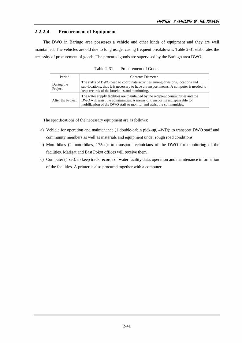
CHAPTERCHAPTERCHAPTERCHAPTER 2 CONTENTSCONTENTSCONTENTSCONTENTS OFOFOFOF THETHETHETHE PROJECTPROJECTPROJECTPROJECT
2-41
2-2-2-4 Procurement of Equipment
The DWO in Baringo area possesses a vehicle and other kinds of equipment and they are well
maintained. The vehicles are old due to long usage, casing frequent breakdowns. Table 2-31 elaborates the
necessity of procurement of goods. The procured goods are supervised by the Baringo area DWO.
Table 2-31 Procurement of Goods
Period Contents Diameter
During the Project
The staffs of DWO need to coordinate activities among divisions, locations and sub-locations, thus it is necessary to have a transport means. A computer is needed to keep records of the boreholes and monitoring.
After the Project The water supply facilities are maintained by the recipient communities and the DWO will assist the communities. A means of transport is indispensable for mobilization of the DWO staff to monitor and assist the communities.
The specifications of the necessary equipment are as follows:
a) Vehicle for operation and maintenance (1 double-cabin pick-up, 4WD): to transport DWO staff and
community members as well as materials and equipment under rough road conditions.
b) Motorbikes (2 motorbikes, 175cc): to transport technicians of the DWO for monitoring of the
facilities. Marigat and East Pokot offices will receive them.
c) Computer (1 set): to keep track records of water facility data, operation and maintenance information
of the facilities. A printer is also procured together with a computer.
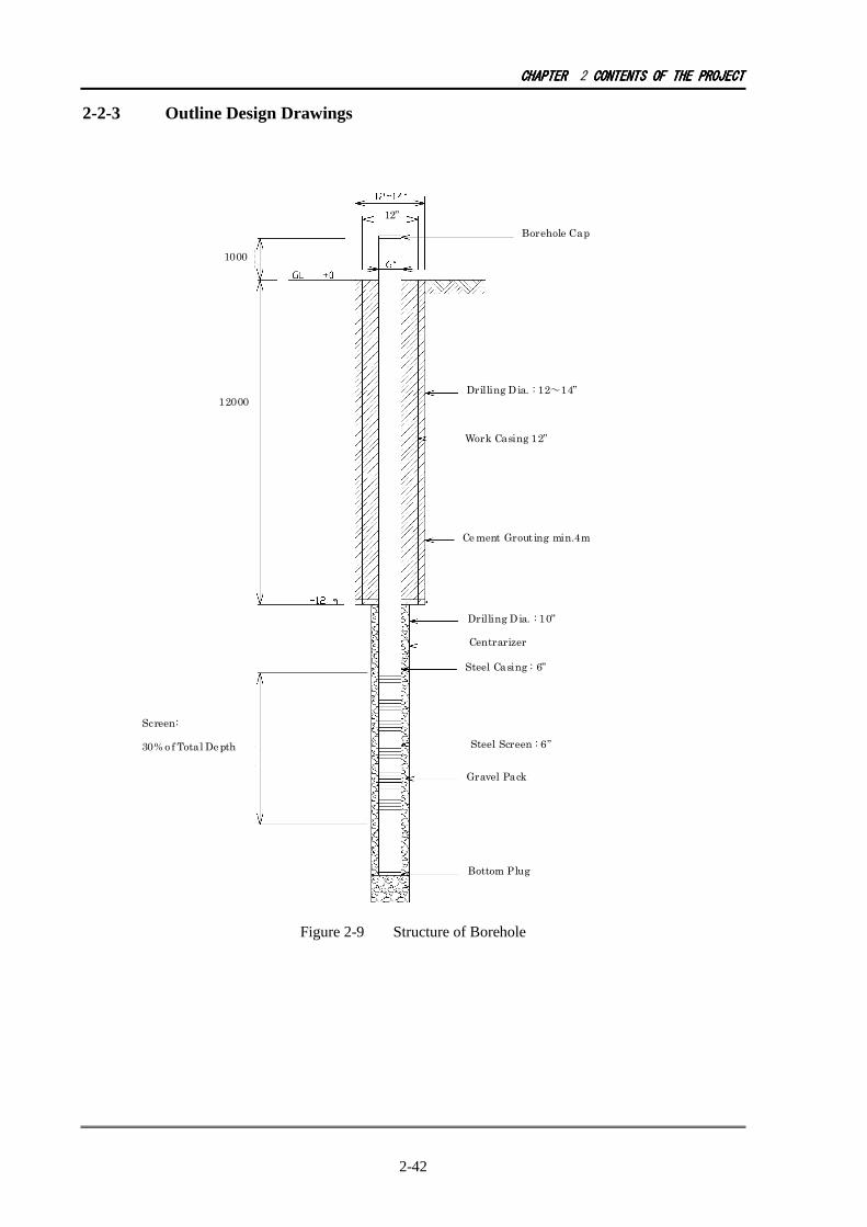
CHAPTERCHAPTERCHAPTERCHAPTER 2 CONTENTSCONTENTSCONTENTSCONTENTS OFOFOFOF THETHETHETHE PROJECTPROJECTPROJECTPROJECT
2-42
2-2-3 Outline Design Drawings
Figure 2-9 Structure of Borehole
12”
12”
Ce ment Grout ing min.4m
Borehole Cap
Drilling Dia. : 12~14”
Work Casing 12”
Drilling Dia. : 10”
Bottom Plug
Screen:
30% o f Total Depth
12000
1000
Centrarizer
Steel Casing : 6”
Steel Screen : 6”
Gravel Pack
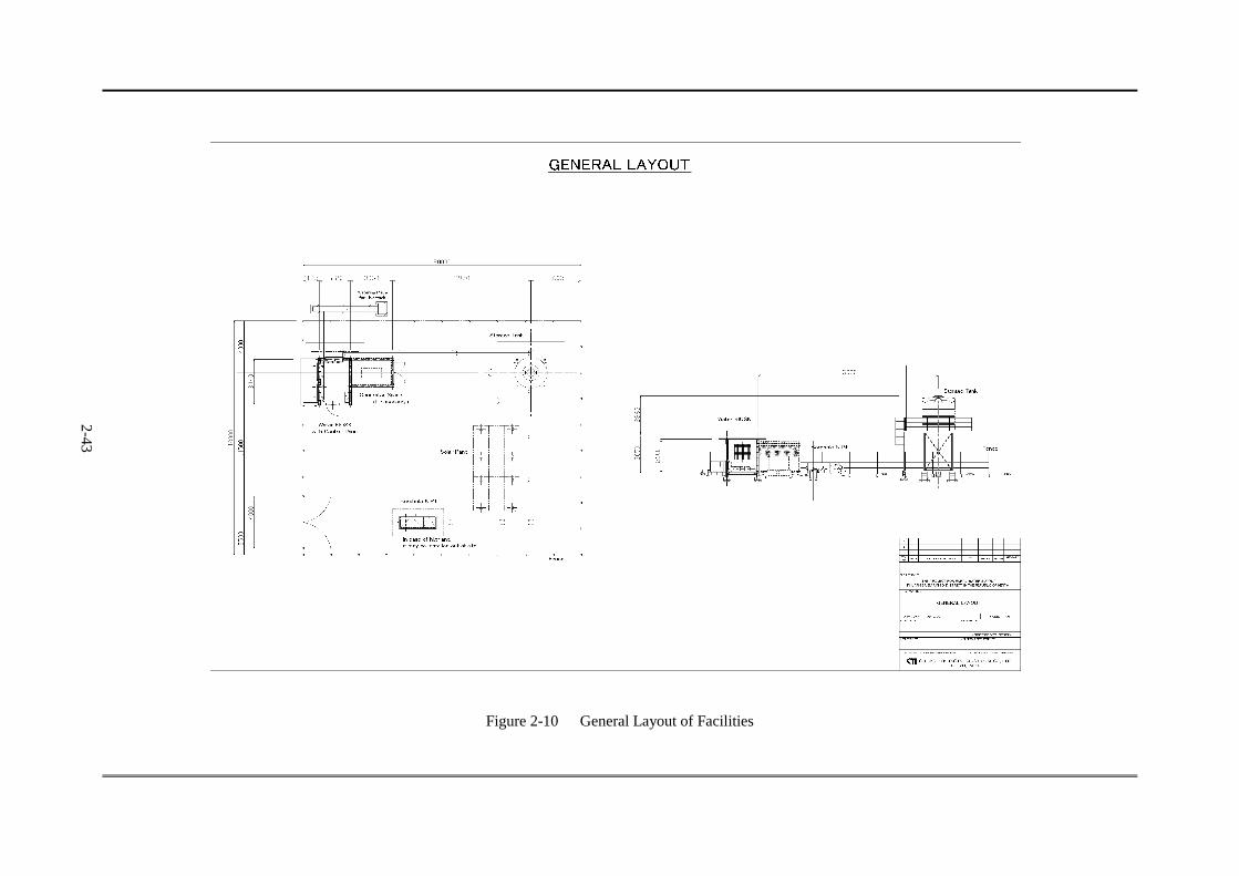
2-43
Figure 2-10 General Layout of Facilities
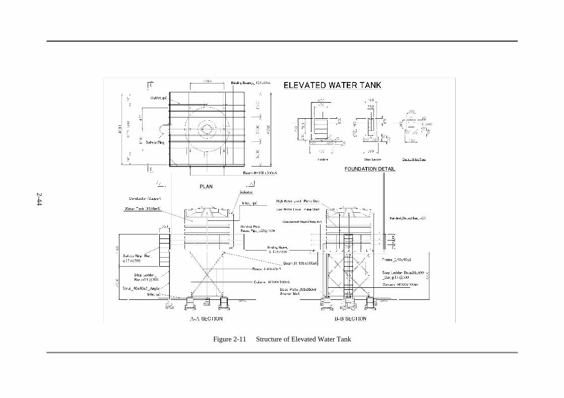
2-44
Figure 2-11 Structure of Elevated Water Tank

2-45
Figure 2-12 Solar Panel

2-46
Figure 2-13 Water Kiosk, Generator Room, Water Trough
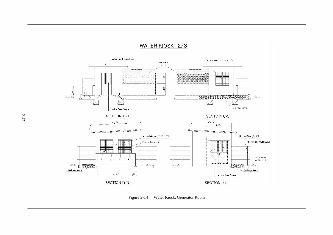
2-47
Figure 2-14 Water Kiosk, Generator Room

2-48
Figure 2-15 Intake Facility
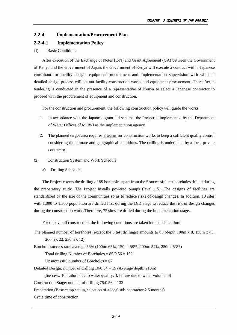
CHAPTERCHAPTERCHAPTERCHAPTER 2222 CONTENTSCONTENTSCONTENTSCONTENTS OFOFOFOF THETHETHETHE PROJECTPROJECTPROJECTPROJECT
2-49
2-2-4 Implementation/Procurement Plan
2-2-4-1 Implementation Policy
(1) Basic Conditions
After execution of the Exchange of Notes (E/N) and Grant Agreement (GA) between the Government
of Kenya and the Government of Japan, the Government of Kenya will execute a contract with a Japanese
consultant for facility design, equipment procurement and implementation supervision with which a
detailed design process will set out facility construction works and equipment procurement. Thereafter, a
tendering is conducted in the presence of a representative of Kenya to select a Japanese contractor to
proceed with the procurement of equipment and construction.
For the construction and procurement, the following construction policy will guide the works:
1. In accordance with the Japanese grant aid scheme, the Project is implemented by the Department
of Water Offices of MOWI as the implementation agency.
2. The planned target area requires 3 teams for construction works to keep a sufficient quality control
considering the climate and geographical conditions. The drilling is undertaken by a local private
contractor.
(2) Construction System and Work Schedule
a) Drilling Schedule
The Project covers the drilling of 85 boreholes apart from the 5 successful test boreholes drilled during
the preparatory study. The Project installs powered pumps (level 1.5). The designs of facilities are
standardized by the size of the communities so as to reduce risks of design changes. In addition, 10 sites
with 1,000 to 1,500 population are drilled first during the D/D stage to reduce the risk of design changes
during the construction work. Therefore, 75 sites are drilled during the implementation stage.
For the overall construction, the following conditions are taken into consideration:
The planned number of boreholes (except the 5 test drillings) amounts to 85 (depth 100m x 8, 150m x 43,
200m x 22, 250m x 12)
Borehole success rate: average 56% (100m: 65%, 150m: 58%, 200m: 54%, 250m: 53%)
Total drilling Number of Boreholes = 85/0.56 = 152
Unsuccessful number of Boreholes = 67
Detailed Design: number of drilling 10/0.54 = 19 (Average depth: 210m)
(Success: 10, failure due to water quality: 3, failure due to water volume: 6)
Construction Stage: number of drilling 75/0.56 = 133
Preparation (Base camp set up, selection of a local sub-contractor 2.5 months)
Cycle time of construction
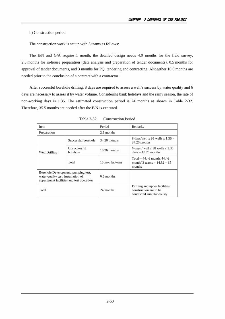
CHAPTERCHAPTERCHAPTERCHAPTER 2222 CONTENTSCONTENTSCONTENTSCONTENTS OFOFOFOF THETHETHETHE PROJECTPROJECTPROJECTPROJECT
2-50
b) Construction period
The construction work is set up with 3 teams as follows:
The E/N and G/A require 1 month, the detailed design needs 4.0 months for the field survey,
2.5 months for in-house preparation (data analysis and preparation of tender documents), 0.5 months for
approval of tender documents, and 3 months for PQ, tendering and contracting. Altogether 10.0 months are
needed prior to the conclusion of a contract with a contractor.
After successful borehole drilling, 8 days are required to assess a well’s success by water quality and 6
days are necessary to assess it by water volume. Considering bank holidays and the rainy season, the rate of
non-working days is 1.35. The estimated construction period is 24 months as shown in Table 2-32.
Therefore, 35.5 months are needed after the E/N is executed.
Table 2-32 Construction Period
Item Period Remarks
Preparation 2.5 months
Successful borehole 34.20 months 8 days/well x 95 wells x 1.35 = 34.20 months
Unsuccessful borehole
10.26 months 6 days / well x 38 wells x 1.35 days = 10.26 months Well Drilling
Total 15 months/team Total=44.46 month, 44.46 month/ 3 teams = 14.82 = 15 months
Borehole Development, pumping test, water quality test, installation of appurtenant facilities and test operation
6.5 months
Total 24 months Drilling and upper facilities construction are to be conducted simultaneously.
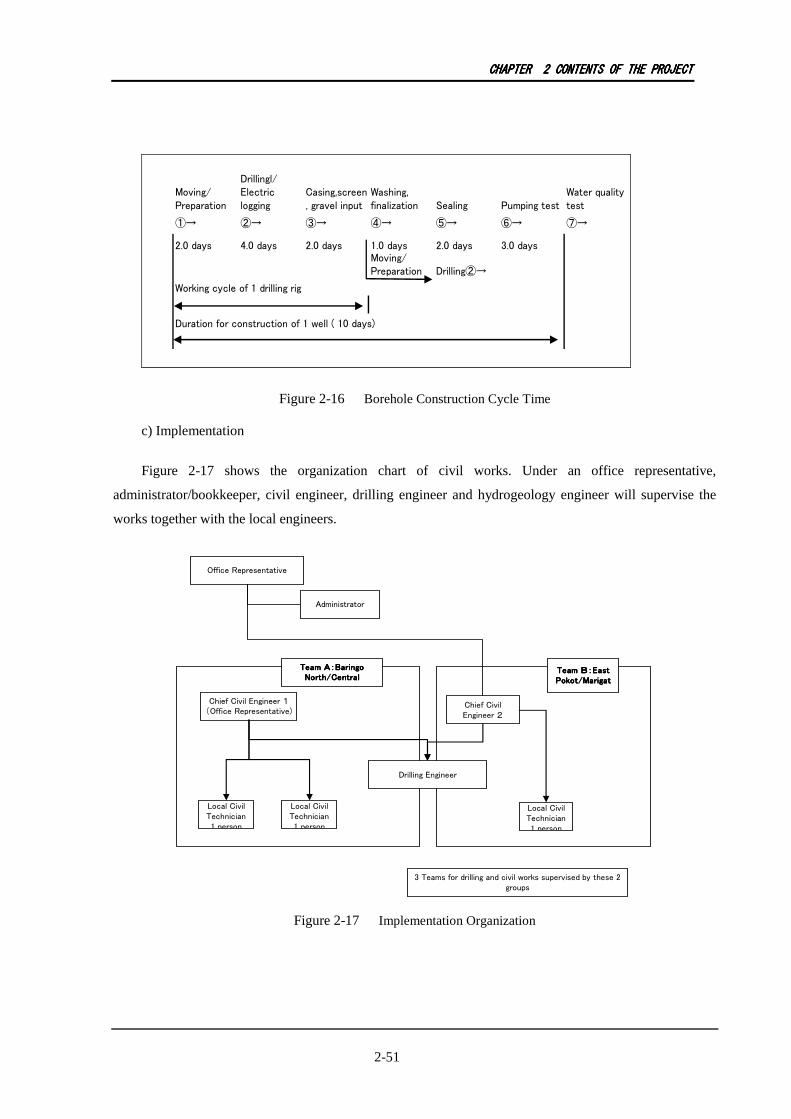
CHAPTERCHAPTERCHAPTERCHAPTER 2222 CONTENTSCONTENTSCONTENTSCONTENTS OFOFOFOF THETHETHETHE PROJECTPROJECTPROJECTPROJECT
2-51
Moving/
Preparation
Drillingl/
Electric
logging
Casing,screen
, gravel input
Washing,
finalization Sealing Pumping test
Water quality
test
①→ ②→ ③→ ④→ ⑤→ ⑥→ ⑦→
2.0 days 4.0 days 2.0 days 1.0 days 2.0 days 3.0 days
Moving/
Preparation Drilling②→
Duration for construction of 1 well ( 10 days)
Working cycle of 1 drilling rig
Figure 2-16 Borehole Construction Cycle Time
c) Implementation
Figure 2-17 shows the organization chart of civil works. Under an office representative,
administrator/bookkeeper, civil engineer, drilling engineer and hydrogeology engineer will supervise the
works together with the local engineers.
Chief Civil Engineer 1
(Office Representative)
Office Representative
Administrator
Chief Civil
Engineer 2
Drilling Engineer
Local Civil
Technician
1 person
Team A:BaringoTeam A:BaringoTeam A:BaringoTeam A:Baringo
North/CentralNorth/CentralNorth/CentralNorth/Central
Team B:EastTeam B:EastTeam B:EastTeam B:East
Pokot/MarigatPokot/MarigatPokot/MarigatPokot/Marigat
3 Teams for drilling and civil works supervised by these 2
groups
Local Civil
Technician
1 person
Local Civil
Technician
1 person
Figure 2-17 Implementation Organization

CHAPTERCHAPTERCHAPTERCHAPTER 2222 CONTENTSCONTENTSCONTENTSCONTENTS OFOFOFOF THETHETHETHE PROJECTPROJECTPROJECTPROJECT
2-52
2-2-4-2 Implementation Conditions
(1) Accessibility to sites
The target communities have no problem of access to sites during the dry season, but during the rainy
seasons road condition gets worse, therefore, it is anticipated that access to certain sites is difficult.
Accessibility needs to be well thought over to plan a construction schedule.
The 90 target sites are scattered in 4 districts in Large Baringo. Paved routes are Route B4 from
Nakuru, from the intersection of Marigat and Kabarnet extending alongside Lake Baringo up to the north
end, and a portion of the route towards west to Kabarnet. All other roads are gravel roads.
On the highland, some parts of unpaved roads are slippery; thus, with the slope transportation by rig is
difficult. In Marigat and East Pokot, certain roads need to cross the river so that during rainy seasons those
routes are inaccessible.
The rainy seasons are April to June and October to November. Access to the communities during
these months is not possible. Working efficiency will thus slow down during the rainy season.
(2) Temporary Construction Yard
The target area spreads over 200km x 100km. Due to poor road conditions in the hills, a temporary
stockyard to keep construction materials and equipment is set up at Marigat which is the entrance to the
district from Nairobi and Nakuru, and in Kabarnet as the base camp for the Project.
(3) Quality Control
The target area has no place to conduct concrete tests. Since the temporary construction yard needs a
concrete testing laboratory (concrete slump test, curing tank), the laboratory may be set up in Kabarnet.
Simple water quality tests are to be conducted at the time of drilling. Samples may be tested either in
Nakuru at RV-WSB or in Nairobi at the laboratory of Kenyatta University for appropriateness as drinking
water.
(4) EIA Application
An environment license is required since the Project is considered as groundwater development. Since
the Project is not intended to be constructed in a forest reserve, a relatively simple project report is
sufficient to acquire a license. Upon submission of the report, the appraisal is made and finished within
45 days. The project report shall consist of the overall features of the Project such as facilities,
environment and interviews with the community members. The report is to be produced by a registered
consultant at NEMA.

CHAPTERCHAPTERCHAPTERCHAPTER 2222 CONTENTSCONTENTSCONTENTSCONTENTS OFOFOFOF THETHETHETHE PROJECTPROJECTPROJECTPROJECT
2-53
(5) Drilling Permission
Drilling works require permission from WRWA, whose process requires 3 months to complete. An
application form should be filled out together with the electrical exploration results as well as data of
existing boreholes in the same area. In the preparatory study, since the timeframe was too short, temporal
application was submitted and accepted for 2 weeks on the condition that the survey data would be
submitted at a later time. For the implementation of the Project, an application is to be submitted during the
D/D stage so as to receive permission prior to the commencement of the works. The process is
administered by RV-WSB.
(6) Power Supply
In the target area, transmission lines are placed along the main route. In many communities there are
no distribution lines placed for community use. The Project may secure power supply for pumps, but the
capacity is too small for construction works. Therefore, for the construction works, a temporal power
generator is needed. In case commercial power supply is used for pumps, an application has to be submitted
to Kenya Electric Power Company. The construction period shall take the necessary timeframe into account
for power supply preparation. The application is administered by RV-WSB.
(7) Water Supply
Tap water is available at the district capital. Since water is scarce in the area, groundwater from the
test borehole is to be utilized for the construction works. Temporal pumps are to be used up to 50% of the
pumping capacity. Civil works shall start after drilling to share water for the construction work.
(8) Means of Communication
Telephone lines are available only in the district capital. Mobile phones are available, yet the network
is feeble in some communities. To establish the necessary communication flow for the project’s
implementation, radio contacts or a satellite phones need to be ready for use in case of emergency.
(9) Accommodation for Japanese Engineers
Some hotels are available in Kabarnet and Marigat and the west of Lake Baringo. In East Pokot, an
accommodation needs to be prepared at the temporary yard.
2-2-4-3 Scope of Work
The Project implemented under the Japanese grant aid scheme will have divisions of work and
procurement between Kenya and Japan as mentioned below.
The implementing agency is MOWI of Kenya as the chief executive office of the Project. The Project
is implemented in accordance with the funding scheme of Japan. Therefore, in the course of project
implementation, necessary administrative procedures need to be processed without delay at each stage. The
responsibilities are as listed below.

CHAPTERCHAPTERCHAPTERCHAPTER 2222 CONTENTSCONTENTSCONTENTSCONTENTS OFOFOFOF THETHETHETHE PROJECTPROJECTPROJECTPROJECT
2-54
1. To conclude a Grant Agreement (GA) based on the Exchange of Notes (E/N);
2. To conclude a contract with a Japanese consultant based on the E/N and GA;
3. To conclude a contract with a Japanese contractor based on the E/N;
4. To open an A/P at the Japanese bank designated in order to pay the contracting fees to the contractor upon conclusion of a contract;
5. To pay service charges to the Japanese bank in accordance with the banking arrangement (upon opening A/P);
6. To open an office for supervision of the works (Mwanza, Neno District Department of Development) and deploy staff;
7. To accord Japanese consultants and contractors such facilities as may be necessary for their entry into Malawi and stay therein and to issue a long term stay permit for the performance of their work and pay the fees (as necessary);
8. To accord Japanese consultants and contractors such facilities as may be necessary for their business and engineer’s registration, and pay the corresponding fees (as necessary);
9. To expropriate land for facility construction (immediately after the contract conclusion);
10. To prepare for access to construction sites;
11. To accord tax exemption with regard to facility construction works and procurement of equipment;
12. To arrange payment of Customs duties for equipment and materials to be procured from Japan or in a third country;
13. To attend inspection of facilities and equipment (upon consultant’s request);
14. To issue a certificate of payment to the consultant and contractor; and
15. To assist community-based operations and maintenance and to provide necessary support after handover of the facilities.
2-2-4-4 Consultant’s Supervision
Construction supervision is provided into 2 stages: detailed design and construction supervision.
The works under the detailed design stage are listed below as to facility construction and procurement
of equipment as stipulated in the basic design.
1. Preparation of detailed design drawings;
2. Preparation of specifications of construction works and procurement of equipment;
3. Preparation of tender documents;
4. Calculation of bidding target price;and
5. Execution of tendering process.
The contents of the field survey for the detailed design are as follows:
1. Electric exploration to determine the drilling points (vertical and horizontal exploration for 152 drilling points);
2. Analysis of the electric exploration to determine the drilling points (2 point markings at each site);
3. Drilling (19 sites of drilling to produce 10 success sites);

CHAPCHAPCHAPCHAPTERTERTERTER 2222 CONTENTSCONTENTSCONTENTSCONTENTS OFOFOFOF THETHETHETHE PROJECTPROJECTPROJECTPROJECT
2-55
4. Upper facility construction study and design at sites (simplified survey and soil examination);
5. Construction and operation and maintenance support (soft component);
6. Confirmation of construction and procurement plan;
7. Market research for cost estimation; and
8. Additional survey for the detailed design study.
The works at the construction supervision stage are as listed below.
1. Approval of the construction plan, design, as well as inspection of materials;
2. Confirmation of works of the Kenya side;
3. Supervision of progress of works;
4. Supervision of facility construction;
5. Report to both countries’ authorities as to the progress of the works;
6. Supervision of delivery progress of procured equipment and materials;
7. Supervision of procurement and inspection before delivery;
8. Completion of inspection; and
9. Cooperation with payments and other administrative processes.
Listed below are the engineers/experts necessary at each stage to conduct the stipulated tasks:
A. Detailed Design Stage
Chief Engineer 1 person Manager
Hydrogeologist 1 1 person Electrical exploration, soil examination supervision, borehole site selection
Hydrogeologist 2 1 person ditto
Drilling Engineer 1 person Drilling supervision, borehole structure design
Assistant Chief/Civil Engineer 1 person Facility design and operation, construction supervision
Procurement/Cost Estimation Expert 1 person Civil works and procurement planning/cost estimation
Civil Engineer 2 1 person Coordinator, tender documents preparation
B. Construction Supervision Stage
Chief Engineer 1 person Commencement and completion of the works
Civil Engineer 1 person Commencement of the facility construction and completion of the works
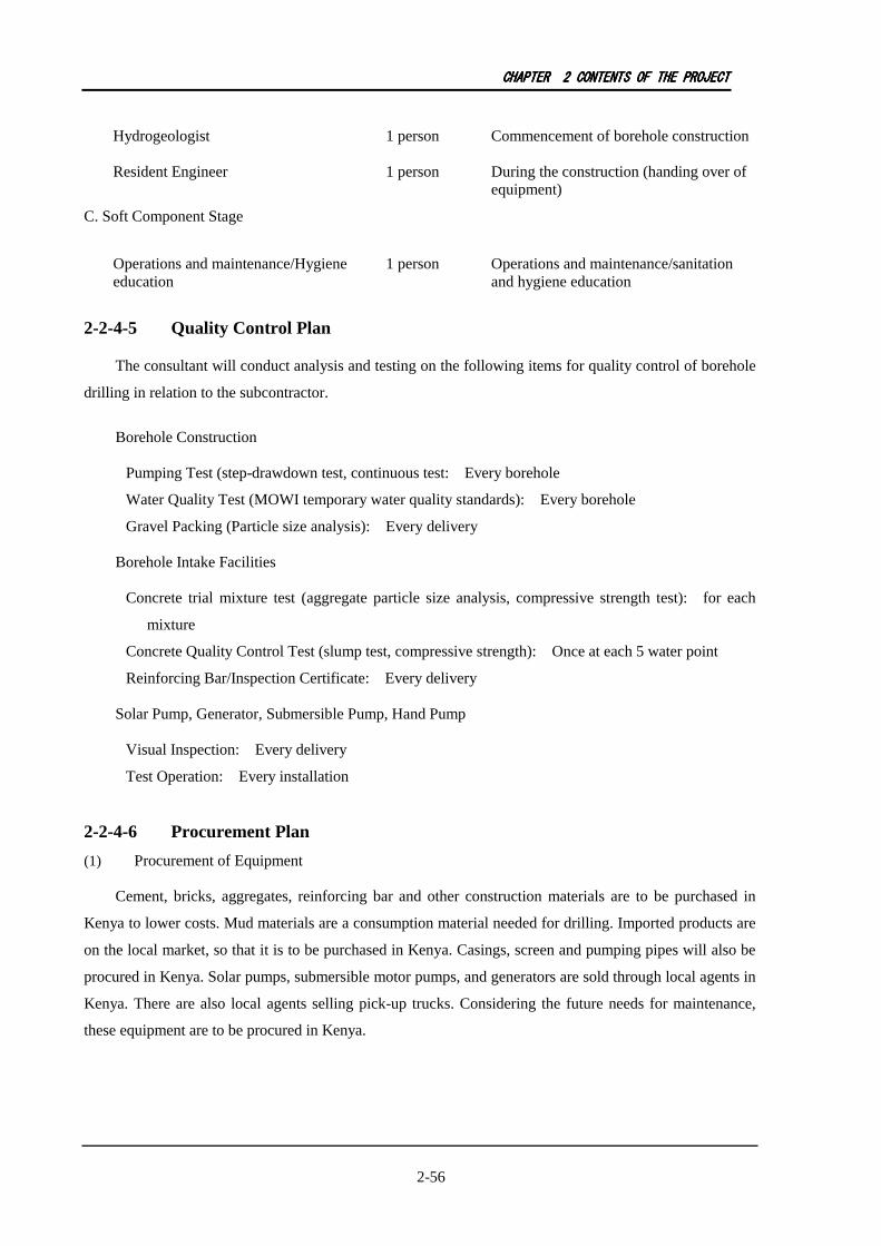
CHAPTERCHAPTERCHAPTERCHAPTER 2222 CONTENTSCONTENTSCONTENTSCONTENTS OFOFOFOF THETHETHETHE PROJECTPROJECTPROJECTPROJECT
2-56
Hydrogeologist 1 person Commencement of borehole construction
Resident Engineer 1 person During the construction (handing over of equipment)
C. Soft Component Stage
Operations and maintenance/Hygiene education
1 person Operations and maintenance/sanitation and hygiene education
2-2-4-5 Quality Control Plan
The consultant will conduct analysis and testing on the following items for quality control of borehole
drilling in relation to the subcontractor.
Borehole Construction
Pumping Test (step-drawdown test, continuous test: Every borehole
Water Quality Test (MOWI temporary water quality standards): Every borehole
Gravel Packing (Particle size analysis): Every delivery
Borehole Intake Facilities
Concrete trial mixture test (aggregate particle size analysis, compressive strength test): for each
mixture
Concrete Quality Control Test (slump test, compressive strength): Once at each 5 water point
Reinforcing Bar/Inspection Certificate: Every delivery
Solar Pump, Generator, Submersible Pump, Hand Pump
Visual Inspection: Every delivery
Test Operation: Every installation
2-2-4-6 Procurement Plan
(1) Procurement of Equipment
Cement, bricks, aggregates, reinforcing bar and other construction materials are to be purchased in
Kenya to lower costs. Mud materials are a consumption material needed for drilling. Imported products are
on the local market, so that it is to be purchased in Kenya. Casings, screen and pumping pipes will also be
procured in Kenya. Solar pumps, submersible motor pumps, and generators are sold through local agents in
Kenya. There are also local agents selling pick-up trucks. Considering the future needs for maintenance,
these equipment are to be procured in Kenya.

CHAPTERCHAPTERCHAPTERCHAPTER 2222 CONTENTSCONTENTSCONTENTSCONTENTS OFOFOFOF THETHETHETHE PROJECTPROJECTPROJECTPROJECT
2-57
Table 2-33 Countries Planned for the Procurement of Equipment and Materials
No. Items Kenya Third Country Japan
1 Casing ○
2 Screen ○
3 Aggregates ○
4 Cement, reinforcing bars
○
5 Pipes ○
6 Pump ○
7 Solar pump ○
8 Generator ○
9 Double cabin Pick-up Truck
○ ○
10 Motorcycle ○ ○
11 Personal Computer ○ ○ ○
2-2-4-7 Operational Guidance Plan
The initial guidance and instructions for operation and daily maintenance of facilities are given to
WUA members after the completion of facility set up. The instructions are given by the contractor.
2-2-4-8 Soft Component Plan
The following social intervention program is planned for water supply facilities constructed under this
project for their sustainable and effective use. The program aims to strengthen the capacity of communities
for the operation and maintenance to be performed by them.
(1) Background of Soft Component
The target communities have no water supply facilities; therefore, after installation of the facilities, it
is necessary to provide support and training on maintenance and operation. According to Kenya’s
sustainable operation and maintenance strategy, the training and sensitization program is planned to
strengthen the capacity of local communities.
(2) Objective
The goal of the program is “to form a water users association by the local communities, which carries
out the operation and maintenance of facilities at village level water supply, and water supply facilities can
be used sustainably” and, in addition, to strengthen the capacity of the DWO staff to provide support to the
local communities.
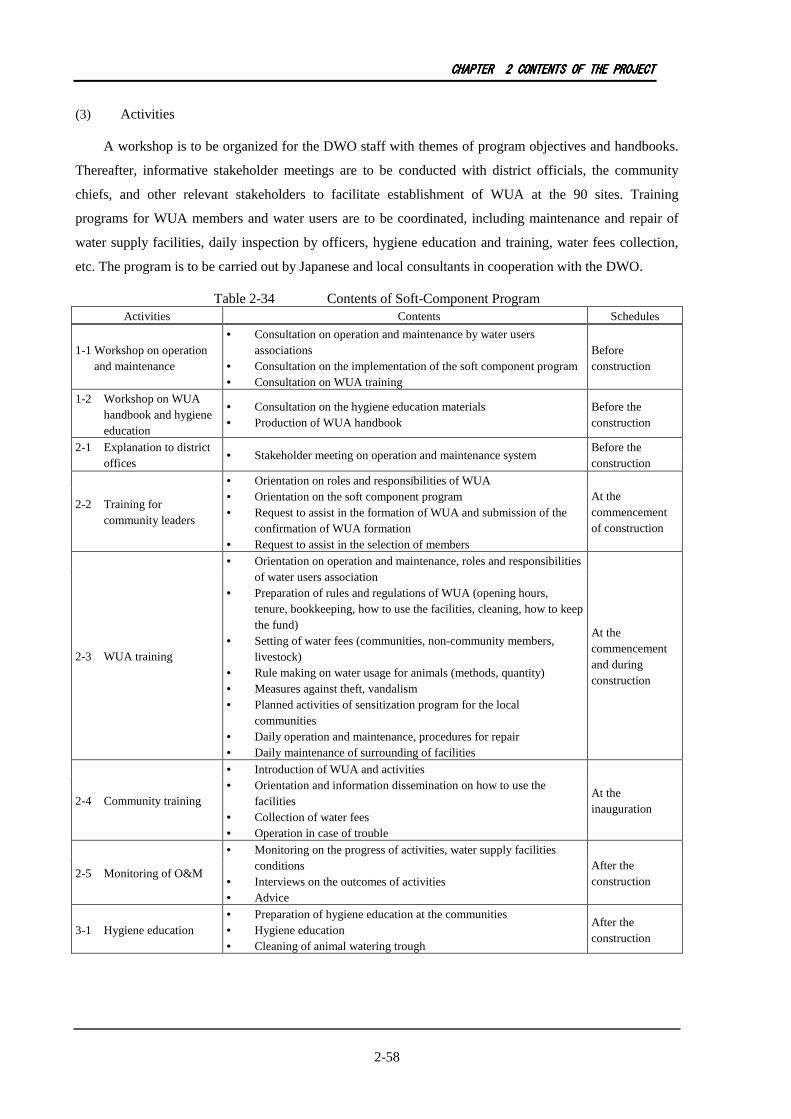
CHAPTERCHAPTERCHAPTERCHAPTER 2222 CONTENTSCONTENTSCONTENTSCONTENTS OFOFOFOF THETHETHETHE PROJECTPROJECTPROJECTPROJECT
2-58
(3) Activities
A workshop is to be organized for the DWO staff with themes of program objectives and handbooks.
Thereafter, informative stakeholder meetings are to be conducted with district officials, the community
chiefs, and other relevant stakeholders to facilitate establishment of WUA at the 90 sites. Training
programs for WUA members and water users are to be coordinated, including maintenance and repair of
water supply facilities, daily inspection by officers, hygiene education and training, water fees collection,
etc. The program is to be carried out by Japanese and local consultants in cooperation with the DWO.
Table 2-34 Contents of Soft-Component Program Activities Contents Schedules
1-1 Workshop on operation and maintenance
• Consultation on operation and maintenance by water users associations
• Consultation on the implementation of the soft component program • Consultation on WUA training
Before construction
1-2 Workshop on WUA handbook and hygiene education
• Consultation on the hygiene education materials • Production of WUA handbook
Before the construction
2-1 Explanation to district offices
• Stakeholder meeting on operation and maintenance system Before the construction
2-2 Training for community leaders
• Orientation on roles and responsibilities of WUA • Orientation on the soft component program • Request to assist in the formation of WUA and submission of the
confirmation of WUA formation • Request to assist in the selection of members
At the commencement of construction
2-3 WUA training
• Orientation on operation and maintenance, roles and responsibilities of water users association
• Preparation of rules and regulations of WUA (opening hours, tenure, bookkeeping, how to use the facilities, cleaning, how to keep the fund)
• Setting of water fees (communities, non-community members, livestock)
• Rule making on water usage for animals (methods, quantity) • Measures against theft, vandalism • Planned activities of sensitization program for the local
communities • Daily operation and maintenance, procedures for repair • Daily maintenance of surrounding of facilities
At the commencement and during construction
2-4 Community training
• Introduction of WUA and activities • Orientation and information dissemination on how to use the
facilities • Collection of water fees • Operation in case of trouble
At the inauguration
2-5 Monitoring of O&M
• Monitoring on the progress of activities, water supply facilities conditions
• Interviews on the outcomes of activities • Advice
After the construction
3-1 Hygiene education • Preparation of hygiene education at the communities • Hygiene education • Cleaning of animal watering trough
After the construction
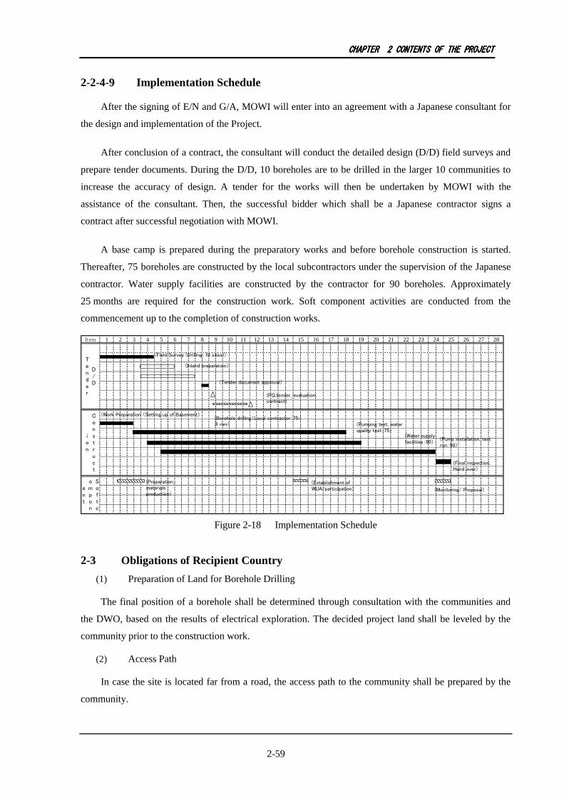
CHAPTERCHAPTERCHAPTERCHAPTER 2222 CONTENTSCONTENTSCONTENTSCONTENTS OFOFOFOF THETHETHETHE PROJECTPROJECTPROJECTPROJECT
2-59
2-2-4-9 Implementation Schedule
After the signing of E/N and G/A, MOWI will enter into an agreement with a Japanese consultant for
the design and implementation of the Project.
After conclusion of a contract, the consultant will conduct the detailed design (D/D) field surveys and
prepare tender documents. During the D/D, 10 boreholes are to be drilled in the larger 10 communities to
increase the accuracy of design. A tender for the works will then be undertaken by MOWI with the
assistance of the consultant. Then, the successful bidder which shall be a Japanese contractor signs a
contract after successful negotiation with MOWI.
A base camp is prepared during the preparatory works and before borehole construction is started.
Thereafter, 75 boreholes are constructed by the local subcontractors under the supervision of the Japanese
contractor. Water supply facilities are constructed by the contractor for 90 boreholes. Approximately
25 months are required for the construction work. Soft component activities are conducted from the
commencement up to the completion of construction works.
Item 1 2 3 4 5 6 7 8 9 10 11 12 13 14 15 16 17 18 19 20 21 22 23 24 25 26 27 28
C
o
n
s
t
r
u
c
t
i
o
n
S
o
f
t
c
o
m
p
o
n
e
n
t
D
/
D
T
e
n
d
e
r
(Inland preparation)
(Tender document approval)
(PQ,tender, evaluation,
contract)
(Borehole drilling(Local contractor:75/
3 rigs)
(Water supply
facilities:90)
(Pumping test, water
quality test:75)
(Pump installation, test
run:90)
(Final inspection,
Hand over)
(Preperation,
materials
production)
(Work Preparation (Setting up of Basement)
(Establishment of
WUA/participation)(Monitoring/ Proposal)
(Field Survey (Drilling:10 sites))
Figure 2-18 Implementation Schedule
2-3 Obligations of Recipient Country
(1) Preparation of Land for Borehole Drilling
The final position of a borehole shall be determined through consultation with the communities and
the DWO, based on the results of electrical exploration. The decided project land shall be leveled by the
community prior to the construction work.
(2) Access Path
In case the site is located far from a road, the access path to the community shall be prepared by the
community.
CHAPTERCHAPTERCHAPTERCHAPTER 2222 CONTENTSCONTENTSCONTENTSCONTENTS OFOFOFOF THETHETHETHE PROJECTPROJECTPROJECTPROJECT
2-60
(3) Securing Land for the Project Office, Stockyard and Warehouse
Land for the base camp for construction works needs to be provided by Kenya. A stockyard,
warehouses to keep cement and aggregate as well as fuel and vehicles also need to be provided.
(4) Works of Commercial Electricity Lead-in to the Site
Commercial grid needs to be led in to the target 37 sites until the incoming panels.
(5) Placement of Project Staff and Budget
Project personnel shall be selected from DWO and RV-WSB which are in charge of coordination of the
Project. Direct personnel costs such as allowance and transportation shall be budgeted prior to the
commencement of construction work.
(6) Permission of Drilling and EIA Procedure
The procedures of EIA and permission for drilling shall be expeditiously processed.
(7) Coordination with Other Donors, NGOs and Other Related Agencies
MOWI shall coordinate with other donors and projects to avoid implementing overlapping activities
and projects.
2-4 Project Operation Plan
2-4-1 Supporting System of the Executing Agencies
The operation and maintenance plan has the following conceptual framework: 1) promotion of
communities’ proactive participation in the operation and maintenance; and 2) assistance to communities
bygovernment agencies.
2-4-2 Operation and Maintenance Plan
(1) Basic Policy on Operation and Maintenance
Operation and maintenance of water facilities is to be carried out through the proactive participation of
local community organizations and the administrative support services in Kenya.
After the sector reform under the 2002 Water Act, the responsibilities of support services for rural
communities were transferred to the Water Service Board (WSB). NGOs, private sector and community
based organizations provide the services. In Large Baringo, a water service provider operates in Kabarnet.
For the rural areas, water users associations maintain the water facilities and, in addition, RV-WSB
carries out the support services. The study team had confirmed that RV-WSB is to keep the same operation
and maintenance system, whereby water users associations are established and DWO’s capacity building
is carried out to support the rural communities.
(2) Operation and Maintenance Plan
a) Community support by the local administration
CHAPTERCHAPTERCHAPTERCHAPTER 2222 CONTENTSCONTENTSCONTENTSCONTENTS OFOFOFOF THETHETHETHE PROJECTPROJECTPROJECTPROJECT
2-61
For sustainable operation and maintenance of the water supply facilities, improvement of
communities’ operation and maintenance capacity is a necessity. Training and monitoring are also
necessary to facilitate the process.
The following are the roles and responsibilities expected to be provided by DWO:
• Support to establish water users association (WUA)
• Technical guidance for operation and maintenance
• Training and guidance to the communities to determine water fees and fee collection system
• Training on bookkeeping and fund management
• Support for the repair and rehabilitation of the facilities
• Monitoring
The Project aims to incorporate participative operation and maintenance approach in cooperation with
DWO. A soft-component program intervenes to improve the capacity for operation and maintenance.
b) Community support by the local administration
A participative operation and maintenance system puts emphasis on ownership and cost sharing by the
users. The Project will request the local communities to participate in deciding the borehole drilling points
and to prepare the access for rigs to enter into their communities.
c) Improvement of operation and maintenance capacity
A soft component program will be provided to assist in the set up of a WUA and propose an initial
training. The WUA members are to be elected from community members at regular intervals in the future;
therefore, the roles and responsibilities need to be well defined and transparent to all community members.
The Project will provide an operation and maintenance manual to each village to guide and help the
communities in long term operation and maintenance activities.
2-5 Project Cost Estimation
The breakdown of the cost charged to Kenya to implement the project through a Japanese grant aid
has been estimated as presented below. Kenyan and Japanese sides are expected to bear the costs
respectively. However, the amount does not show the limit of grant aid.
(1) Estimated Project Cost covered by Kenya:
Total Approx. 30.09 million Ksh (28.66 million Japanese Yen)
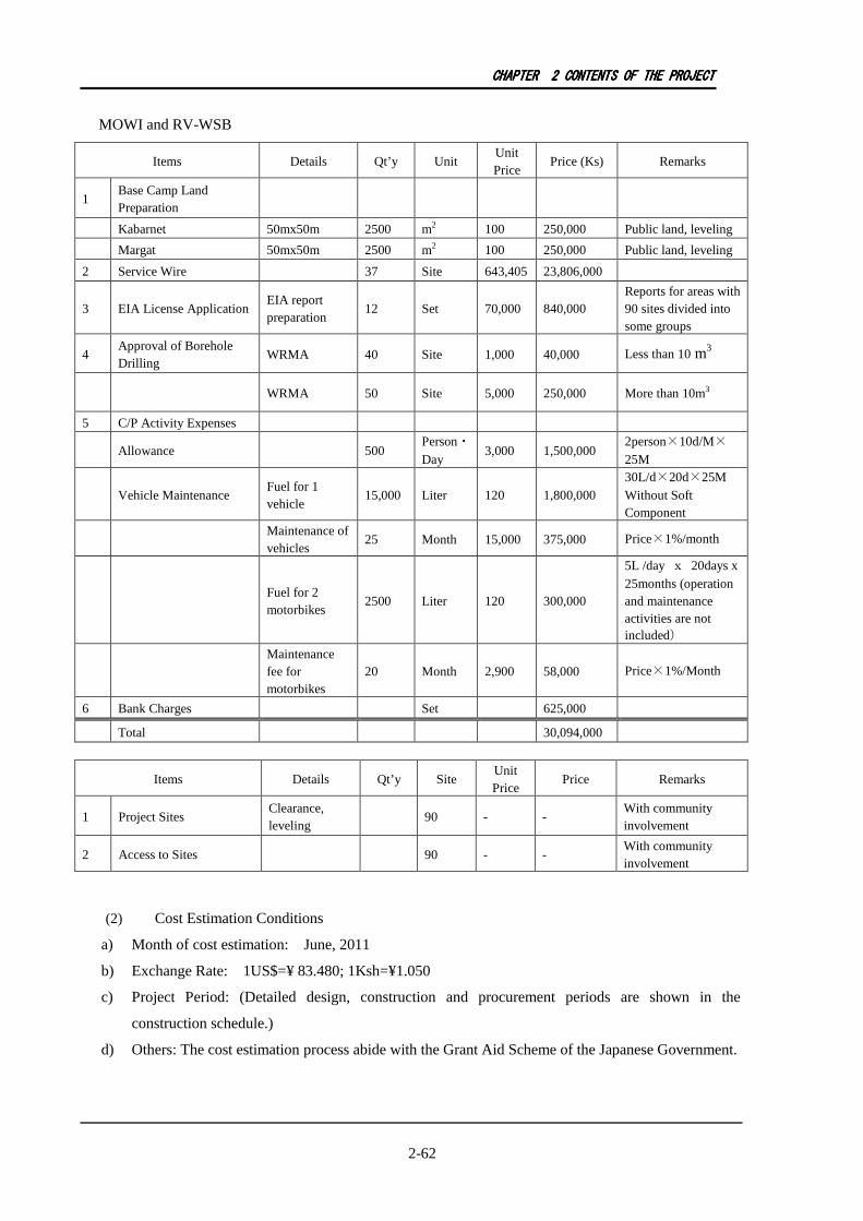
CHAPTERCHAPTERCHAPTERCHAPTER 2222 CONTENTSCONTENTSCONTENTSCONTENTS OFOFOFOF THETHETHETHE PROJECTPROJECTPROJECTPROJECT
2-62
MOWI and RV-WSB
Items Details Qt’y Unit Unit Price
Price (Ks) Remarks
1 Base Camp Land Preparation
Kabarnet 50mx50m 2500 m2 100 250,000 Public land, leveling
Margat 50mx50m 2500 m2 100 250,000 Public land, leveling
2 Service Wire 37 Site 643,405 23,806,000
3 EIA License Application EIA report preparation
12 Set 70,000 840,000 Reports for areas with 90 sites divided into some groups
4 Approval of Borehole Drilling
WRMA 40 Site 1,000 40,000 Less than 10 m3
WRMA 50 Site 5,000 250,000 More than 10m3
5 C/P Activity Expenses
Allowance 500 Person・Day
3,000 1,500,000 2person×10d/M×
25M
Vehicle Maintenance Fuel for 1 vehicle
15,000 Liter 120 1,800,000 30L/d×20d×25M Without Soft Component
Maintenance of vehicles
25 Month 15,000 375,000 Price×1%/month
Fuel for 2 motorbikes
2500 Liter 120 300,000
5L /day x 20days x 25months (operation and maintenance activities are not included)
Maintenance fee for motorbikes
20 Month 2,900 58,000 Price×1%/Month
6 Bank Charges Set 625,000
Total 30,094,000
Items Details Qt’y Site Unit Price
Price Remarks
1 Project Sites Clearance, leveling
90 - - With community involvement
2 Access to Sites 90 - - With community involvement
(2) Cost Estimation Conditions
a) Month of cost estimation: June, 2011
b) Exchange Rate: 1US$=¥ 83.480; 1Ksh=¥1.050
c) Project Period: (Detailed design, construction and procurement periods are shown in the
construction schedule.)
d) Others: The cost estimation process abide with the Grant Aid Scheme of the Japanese Government.

CHAPTERCHAPTERCHAPTERCHAPTER 2222 CONTENTSCONTENTSCONTENTSCONTENTS OFOFOFOF THETHETHETHE PROJECTPROJECTPROJECTPROJECT
2-63
(3) Operation and Maintenance
Operation and maintenance costs are calculated as shown in Table 5-1. The results of social survey
shows that 2 to 3 Ksh per 20L on average are the appropriate water fee range consideringits sustainability.
Although there are communities that pay up to 20 Ksh to water vendors, these are exceptional cases. From
the viewpoint of financial viability, communities with more than 750 population are better off to operate
with a generator pumping system or commercial electric power.
Table 2-2 Operation and Maintenance Cost Estimates
Power Parameters Conditions Operation and Maintenance (Ksh/year)
Size 500 people Fuel - 0 Spare parts, replacement Consumables, 10 years renewal 21,000 Water vendor volunteer 0 Operator 24,000 Others (transport, stationary) 1 set 6,000 Total 51,000
Solar
1 person per day (= per 20L) 0.6 Size 750 people Fuel Fuel per unit Ksh110/L 0 Spare parts, replacement Consumables, 10 years renewal 180,600 Water vendor volunteer 18,000 Operator 72,000 Others (transport, stationary) 1set 6,000 Total 276,600
Generator
1 person per day (= per 20L) 1.0 Size 750 people Fuel KPLC unit price for electricity 449,000 Spare parts, replacement Consumables, 10 years renewal 231,300 Water vendor volunteer 18,000 Operator 72,000 Others (transport, stationary) 1set 6,000 Total 776,300
Commercial grid electric power
1 person per day (= per 20L) 2.8

CHAPTERCHAPTERCHAPTERCHAPTER 3333 PROJECTPROJECTPROJECTPROJECT EVALUATIONEVALUATIONEVALUATIONEVALUATION
3-1
CHAPTER 3 PROJECT EVALUATION
3-1 Preconditions
Many village people in the target communities use water sources such as pond water, river water,
spring water, dug wells and so on. However, the quality and quantity of water sources are not adequate for
drinking purposes; these water sources are contaminated by sewage and livestock excreta and, at the same
time, the quantity fluctuates unstably in the dry season.
The Project will construct new boreholes and water supply facilities, and supply service water to
vehicles and computers for operation and maintenance. Additionally, “soft component” is implemented
such as the training of DWO personnel, capacity building of community organizations, and sanitary
education at the communities.
Preconditions for the Project’s implementation are as follows:
Preparation for borehole drilling sites
Preparation of access route for works
Land preparation for field office, warehouses and yard
Lead-in of commercial power lines
Securing Project Personnel and Budget
RV-WSB: Personnel in charge of the project implementation
DWO: Personnel in charge of practical works
Procedures related to the Project implementation such as borehole drilling permit and Environment
Impact Assessment
3-2 Necessary Inputs by Recipient Country
The issues to be addressed by the Government of Kenya in order to sustain the effects of the Project
are as listed below. The budget of DWO for personnel costs, transportation and others shall be secured to
implement the activities.
DWO will take charge of monitoring and supervision, for sustainable operation and maintenance in
the target communities.
In the target communities, support is given to form a Water Users Association (WUA)

CHAPTERCHAPTERCHAPTERCHAPTER 3333 PROJECTPROJECTPROJECTPROJECT EVALUATIONEVALUATIONEVALUATIONEVALUATION
3-2
3-3 Important Assumptions
External conditions for sustainable effects of the Project are as follows:
Sudden price jump does not occur and the equipment is stably procured.
No significant change in the government’s relevant policies in Kenya.
Weather and road conditions do not deteriorate rapidly.
The safety conditions do not deteriorate.
3-4 Project Evaluation
3-4-1 Relevance
The target of the Project are the communities in the 4 districts of Baringo District located in Rift
Valley Province (Baringo North, Marigat, Baringo Central, and East Pokot). Direct beneficiaries are
approximately 60,000 in 2015, and the proportion of population with access to safe and stable water is
increased from 24% to 37%.
Water sources such as lake water, river water, spring water and dug wells are primarily used as the
main water sources in the area for drinking purposes without any treatment. Consequently, many people are
affected by waterborne diseases. The safety of water sources is thus a serious problem, so that the
improvement of water services is an urgent concern.
New boreholes with pumping facilities constructed in the Project are maintained by the WUAs to be
established at each site. Water fees to cover the maintenance cost are estimated to be around 2 to
3 Ksh/20 liters. Based on the data gathered in the social survey, the estimated water price is acceptable for
the local users and WUAs are advised to conduct operation and maintenance by themselves.
The National Development Plan (Vision 2030) aims at achieving universal access to water resources
and hygiene. The medium-term program of the Millennium Development Goals targets the increase of the
average proportion of population with access to safe and stable water from 40% to 59%. The access rate in
the area is currently 24%; therefore, increasing the access rate to approximately 35.7% will contribute to
the overall objectives.
The category of Environmental and Social Consideration is C (hardly have any adverse impact on
environment and society), thus there is little influence on the environmental and social conditions.

CHAPTERCHAPTERCHAPTERCHAPTER 3333 PROJECTPROJECTPROJECTPROJECT EVALUATIONEVALUATIONEVALUATIONEVALUATION
3-3
3-4-2 Effectiveness
(1) Quantitative Effect
Table 3-1 Quantitative Project Impact
Indicator Base Year
(2011)
Target Year (2017: 3 year after
completion)
Proportion of the population with access to safe and stable water in the area
24.4% 35.7%
Population with access to safe and stable water in the area
98,000
157,580
(2) Qualitative Effect
a) Waterborne diseases such as diarrhea and dysentery are expected to decrease.
b) Labour for the transportation of water is expected to decrease.
c) At 90 sites, WUAs are established to facilitate maintenance, and their capacity for maintenance as
well as ownership is enhanced.
In consideration of the analysis stated above, the validity and effectiveness of the Project is high.