Embed Size (px)
Citation preview
MONTAGE- UND BEDIENUNGSANLEITUNG
STEUEREINHEIT FÜR ROTIERENDE WÄRMETAUSCHER
MicroMax370W
Auch auf Englisch

Safety reference 16
Installation directions 17
Mounting 18
Equipment description 19
Technical data 20
Functions 20-22
- DIP-switch
- Manual run (at test)
- Operation indications
- Alarm
- Adjustments via potentiometer
- Reset push-button
Connection diagram 23
Connections 23
EMC-installation 24
Check before switching on the control unit
24
Putting the equipment into operation
25
Standards / Policies 26
Own notes 27-28
PAGE REFERENCE TO ADAPT
INHALTSVERZEICHNIS ANPASSEN
Sicherheitshinweise 2
Installationshinweise 3
Montage 4
Gerätebeschreibung 5
Technische Angaben 6
Funktionen 6-8
- DIP-schalter
- Manueller Betrieb (zur Prüfung)
- Betriebsanzeigen
- Alarm
- Einstellung via potentiometer
- Reset-drucktaste
Anschlussplan 9
Anschlüsse 9
EMV-installation 10
Prüfung vor Anlegen der Spannung
10
Inbetriebnahme der Anlage 11
Normen / Richtlininen 12
Eigene Notizen 13
2
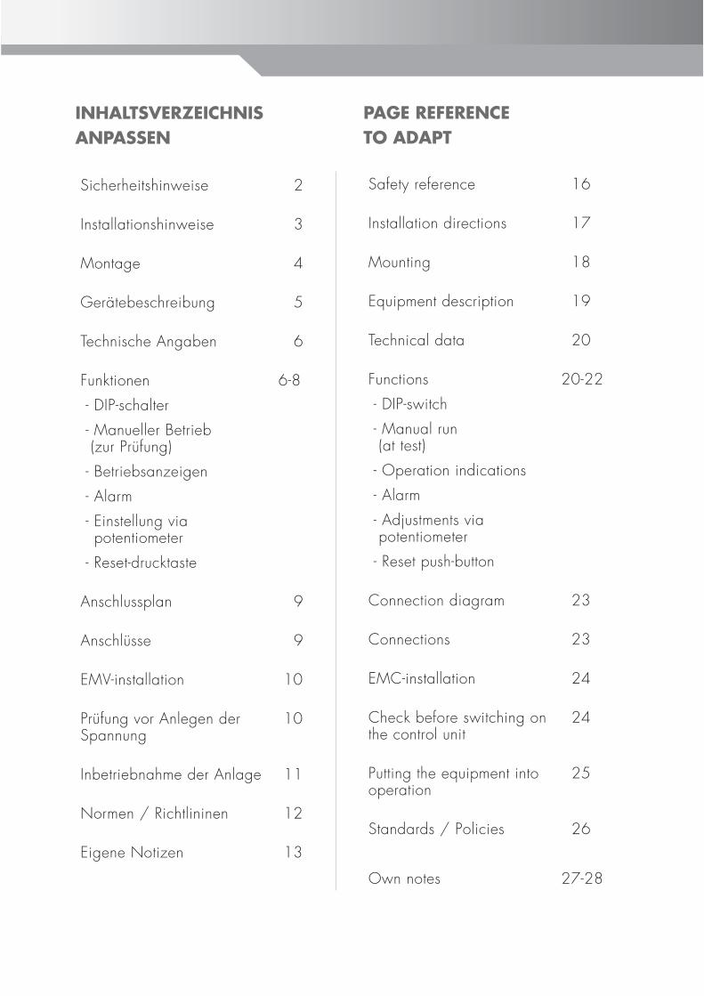
SICHERHEITSHINWEISEIn dieser Beschreibung werden die folgenden Symbole und Hinweiszeichen verwendet. Diese wichtigen Anweisungen betreff en den Personenschutz und die technische Betriebssicherheit.
“Sicherheitshinweis” kennzeichnet Anweisungen, die genau einzuhalten sind, um Gefährdung oder Verletzung von Personen zu vermeiden und Beschädigungen am Gerät zu verhindern.
Gefahr durch elektrische Spannung an elektrischen Bauteilen!Achtung: Vor Abnahme der Verkleidung Betriebsschalter ausschhalten.
Greifen Sie niemals bei eingeschaltetem Betriebsschalter an elektrische Bauteile und Kontakte! Es besteht die Gefahr eines Stromschlages mit Gesundheitsgefährdung oder Todesfolge.
An Anschlussklemmen liegt auch bei ausgeschaltetem Betriebsschalter Spannung an.
“Hinweis” kennzeichnet technische Anweisungen, die zu beachten sind, um Schäden und Funktionsstörungen am Gerät zu verhindern.Achtung
INSTALLATIONSHINWEISEInstallation / Inbetriebnahme
- Die Installation und Inbetriebnahme der Rotorregelung und der angeschlossenen Zubehörteile darf lt. DIN EN 50110-1 nur von Elektrofachkräft en durchgeführt werden.- Die örtlichen EVU-Bestimmungen sowie VDE-Vorschrift en sind einzuhalten.- DIN VDE 0100 Bestimmungen für das Errichten von Starkstromanlagen bis 1000V.- DIN VDE 0105-100 Betrieb von elektrischen Anlagen Ferner gelten für Österreich die ÖVE-Vorschrift en sowie die örtliche Bauordnung.
Warnhinweise - Das Entfernen, Überbrücken oder Außerkraftsetzen von Sicherheits- und Überwachungseinrichtungen ist verboten!- Die Anlage darf nur in technisch einwandfreiem Zustand betrieben werden. Störungen und Schäden, die die Sicherheit beeinträchtigen, müssen umgehend beseitigt werden.
Wartung / Reparatur - Die einwandfreie Funktion der elektrischen Ausrüstung ist in regelmäßigen Abständen zu kontrollieren.- Störungen und Schäden dürfen nur von Fachkräft en beseitigt werden.- Schadhaft e Bauteile dürfen nur durch original Wolf-Ersatzteile ersetzt werden.- Vorgeschriebene elektrische Absicherungswerte sind einzuhalten (siehe Technische Daten).
Werden an Wolf-Regelungen technische Änderungen vorgenommen, übernehmen wir für Schäden, die hierdurch entstehen, keine Gewähr.
Entsorgung und Recycling
Für die Entsorgung defekter Systemkomponenten oder des Systems nach der Produktlebensdauer beachten Sie bitte folgende Hinweise:
Entsorgen Sie sachgerecht, d.h. getrennt nach Materialgruppen der zu entsorgenden Teile. Ziel sollte immer eine möglichst maximale Wiederverwendbarkeit der Grundmaterialien bei möglichst geringer Umweltbelastung sein.
Werfen Sie keinesfalls Elektro- oder Elektronikschrott einfach in den Müll, sondern nutzenn Sie entsprechende Annahmestellen.
Entsorgen Sie grundsätzlich so umweltverträglich, wie es demStand der Umweltschutz-, Wiederaufb ereitungs- und Entsorgungstechnik entspricht.
Achtung
3
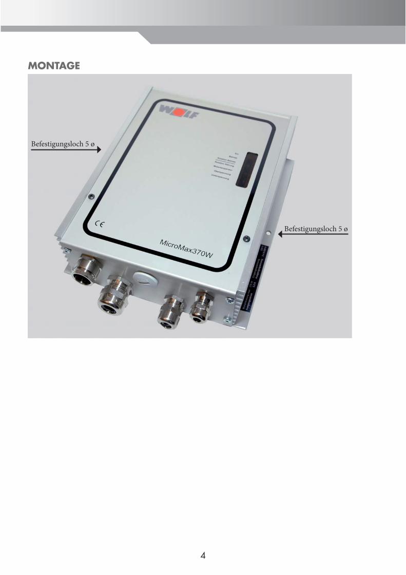
MONTAGE
Befestigungsloch 5 ø
Befestigungsloch 5 ø
4
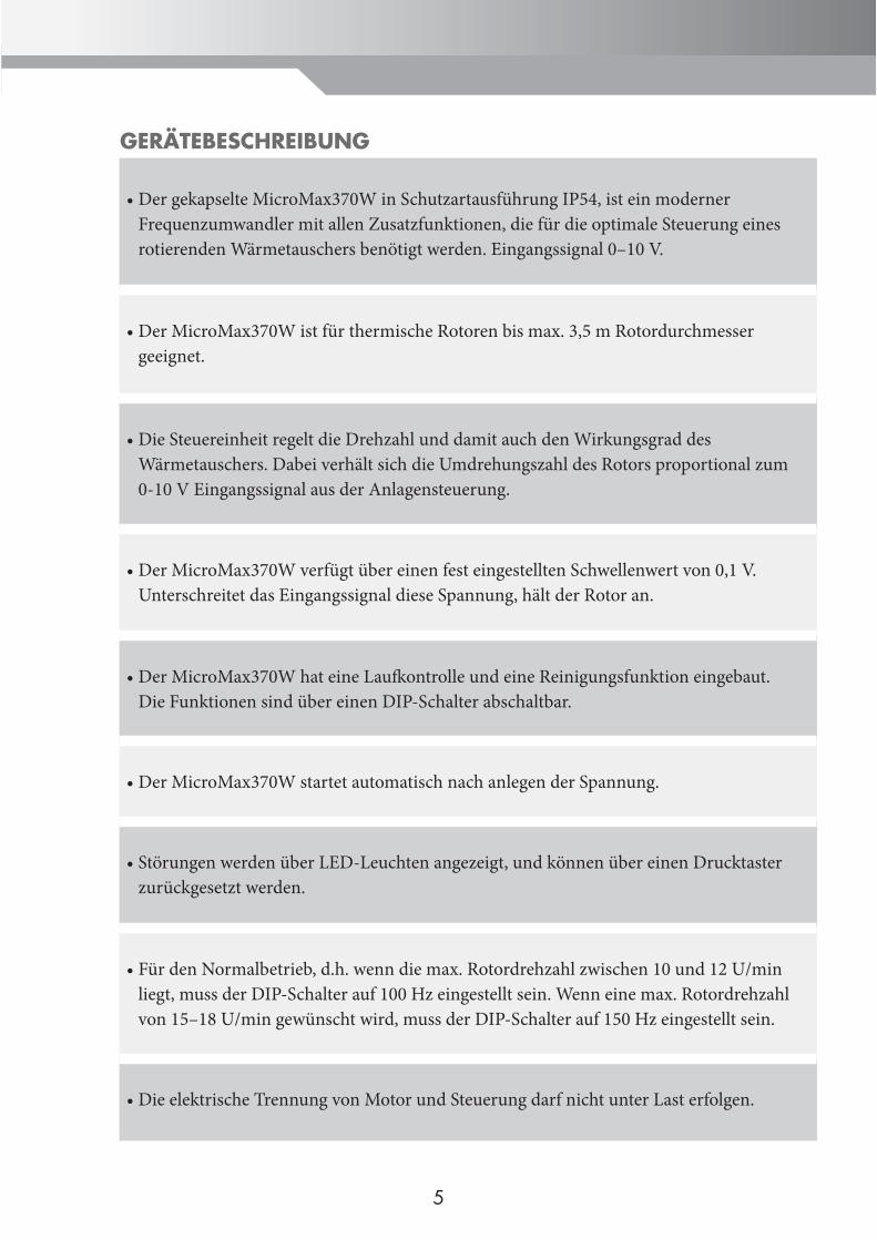
Der gekapselte MicroMax370W in Schutzartausführung IP54, ist ein moderner Frequenzumwandler mit allen Zusatzfunktionen, die für die optimale Steuerung eines rotierenden Wärmetauschers benötigt werden. Eingangssignal 0–10 V.
•
Der MicroMax370W ist für thermische Rotoren bis max. 3,5 m Rotordurchmesser geeignet.
•
Die Steuereinheit regelt die Drehzahl und damit auch den Wirkungsgrad des Wärmetauschers. Dabei verhält sich die Umdrehungszahl des Rotors proportional zum 0-10 V Eingangssignal aus der Anlagensteuerung.
•
Der MicroMax370W verfügt über einen fest eingestellten Schwellenwert von 0,1 V.Unterschreitet das Eingangssignal diese Spannung, hält der Rotor an.
•
Der MicroMax370W hat eine Laufk ontrolle und eine Reinigungsfunktion eingebaut. Die Funktionen sind über einen DIP-Schalter abschaltbar.
•
Der MicroMax370W startet automatisch nach anlegen der Spannung.•
Störungen werden über LED-Leuchten angezeigt, und können über einen Drucktaster zurückgesetzt werden.
•
Für den Normalbetrieb, d.h. wenn die max. Rotordrehzahl zwischen 10 und 12 U/min liegt, muss der DIP-Schalter auf 100 Hz eingestellt sein. Wenn eine max. Rotordrehzahl von 15–18 U/min gewünscht wird, muss der DIP-Schalter auf 150 Hz eingestellt sein.
•
Die elektrische Trennung von Motor und Steuerung darf nicht unter Last erfolgen.•
GERÄTEBESCHREIBUNG
5
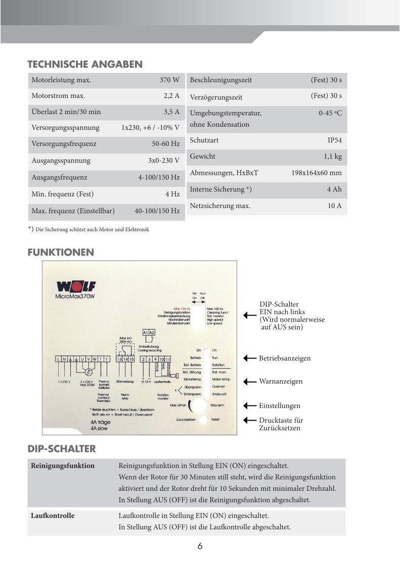
TECHNISCHE ANGABEN
FUNKTIONEN
DIP-SCHALTER
Reinigungsfunktion Reinigungsfunktion in Stellung EIN (ON) eingeschaltet.Wenn der Rotor für 30 Minuten still steht, wird die Reinigungsfunktionaktiviert und der Rotor dreht für 10 Sekunden mit minimaler Drehzahl. In Stellung AUS (OFF) ist die Reinigungsfunktion abgeschaltet.
Laufk ontrolle Laufk ontrolle in Stellung EIN (ON) eingeschaltet.In Stellung AUS (OFF) ist die Laufk ontrolle abgeschaltet.
Beschleunigungszeit (Fest) 30 s
Verzögerungszeit (Fest) 30 s
Umgebungstemperatur,ohne Kondensation
0-45 ºC
Schutzart IP54
Gewicht 1,1 kg
Abmessungen, HxBxT 198x164x60 mm
Interne Sicherung *) 4 Ah
Netzsicherung max. 10 A
Motorleistung max. 370 W
Motorstrom max. 2,2 A
Überlast 2 min/30 min 3,5 A
Versorgungsspannung 1x230, +6 / -10% V
Versorgungsfrequenz 50-60 Hz
Ausgangsspannung 3x0-230 V
Ausgangsfrequenz 4-100/150 Hz
Min. frequenz (Fest) 4 Hz
Max. frequenz (Einstellbar) 40-100/150 Hz
*) Die Sicherung schützt auch Motor und Elektronik
6
Betriebsanzeigen
Warnanzeigen
Drucktaste für Zurücksetzen
DIP-SchalterEIN nach links(Wird normalerweise auf AUS sein)
Einstellungen
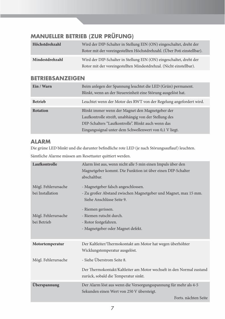
MANUELLER BETRIEB (ZUR PRÜFUNG)Höchstdrehzahl Wird der DIP-Schalter in Stellung EIN (ON) eingeschaltet, dreht der
Rotor mit der voreingestellten Höchstdrehzahl. (Über Poti einstellbar).
Mindestdrehzahl Wird der DIP-Schalter in Stellung EIN (ON) eingeschaltet, dreht der Rotor mit der voreingestellten Mindestdrehzal. (Nicht einstellbar).
BETRIEBSANZEIGENEin / Warn Beim anlegen der Spannung leuchtet die LED (Grün) permanent.
Blinkt, wenn an der Steuereinheit eine Störung ausgelöst hat.
Betrieb Leuchtet wenn der Motor des RWT von der Regelung angefordert wird.
Rotation Blinkt immer wenn der Magnet den Magnetgeber der Laufk ontrolle streift , unabhängig von der Stellung des DIP-Schalters “Laufk ontrolle”. Blinkt auch wenn das Eingangssignal unter dem Schwellenwert von 0,1 V liegt.
ALARMDie grüne LED blinkt und die darunter befi ndliche rote LED (je nach Störungsaufl auf) leuchten.
Sämtliche Alarme müssen am Resettaster quittiert werden.
Laufk ontrolle
Mögl. Fehlerursachebei Installation
Mögl. Fehlerursachebei Betrieb
Alarm löst aus, wenn nicht alle 5 min einen Impuls über den Magnetgeber kommt. Die Funktion ist über einen DIP-Schalter abschaltbar.
- Magnetgeber falsch angeschlossen.- Zu großer Abstand zwischen Magnetgeber und Magnet, max 15 mm. Siehe Anschlüsse Seite 9.
- Riemen gerissen.- Riemen rutscht durch.- Rotor festgefahren.- Magnetgeber oder Magnet defekt.
Motortemperatur
Mögl. Fehlerursache
Der Kaltleiter/Th ermokontakt am Motor hat wegen überhöhter Wicklungstemperatur ausgelöst.
- Siehe Überstrom Seite 8.
Der Th ermokontakt/Kaltleiter am Motor wechselt in den Normal zustand zurück, sobald die Temperatur sinkt.
Überspannung Der Alarm löst aus wenn die Versorgungsspannung für mehr als 4-5 Sekunden einen Wert von 250 V übersteigt. Forts. nächten Seite
7
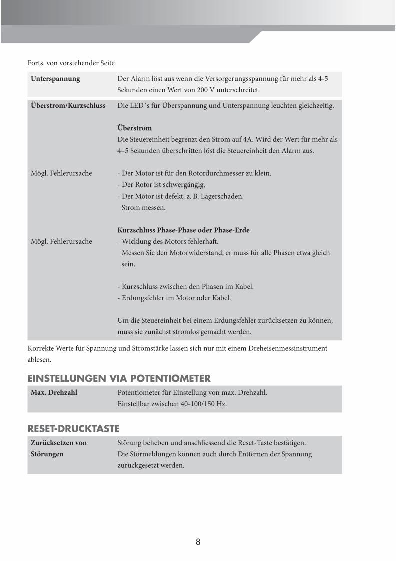
Forts. von vorstehender Seite
Unterspannung Der Alarm löst aus wenn die Versorgerungsspannung für mehr als 4-5 Sekunden einen Wert von 200 V unterschreitet.
Überstrom/Kurzschluss
Mögl. Fehlerursache
Mögl. Fehlerursache
Die LED´s für Überspannung und Unterspannung leuchten gleichzeitig.
ÜberstromDie Steuereinheit begrenzt den Strom auf 4A. Wird der Wert für mehr als 4–5 Sekunden überschritten löst die Steuereinheit den Alarm aus.
- Der Motor ist für den Rotordurchmesser zu klein.- Der Rotor ist schwergängig.- Der Motor ist defekt, z. B. Lagerschaden. Strom messen.
Kurzschluss Phase-Phase oder Phase-Erde- Wicklung des Motors fehlerhaft . Messen Sie den Motorwiderstand, er muss für alle Phasen etwa gleich sein.
- Kurzschluss zwischen den Phasen im Kabel.- Erdungsfehler im Motor oder Kabel.
Um die Steuereinheit bei einem Erdungsfehler zurücksetzen zu können, muss sie zunächst stromlos gemacht werden.
Korrekte Werte für Spannung und Stromstärke lassen sich nur mit einem Dreheisenmessinstrument ablesen.
EINSTELLUNGEN VIA POTENTIOMETERMax. Drehzahl Potentiometer für Einstellung von max. Drehzahl.
Einstellbar zwischen 40-100/150 Hz.
RESET-DRUCKTASTEZurücksetzen von Störungen
Störung beheben und anschliessend die Reset-Taste bestätigen. Die Störmeldungen können auch durch Entfernen der Spannung zurückgesetzt werden.
8
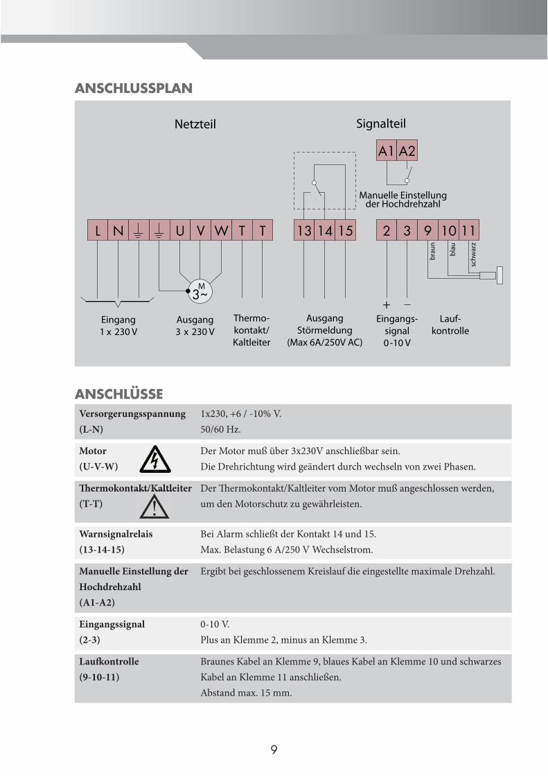
ANSCHLUSSPLAN
ANSCHLÜSSEVersorgerungsspannung(L-N)
1x230, +6 / -10% V.50/60 Hz.
Motor(U-V-W)
Der Motor muß über 3x230V anschließbar sein.Die Drehrichtung wird geändert durch wechseln von zwei Phasen.
Th ermokontakt/Kaltleiter(T-T)
Der Th ermokontakt/Kaltleiter vom Motor muß angeschlossen werden, um den Motorschutz zu gewährleisten.
Warnsignalrelais(13-14-15)
Bei Alarm schließt der Kontakt 14 und 15. Max. Belastung 6 A/250 V Wechselstrom.
Manuelle Einstellung der Hochdrehzahl(A1-A2)
Ergibt bei geschlossenem Kreislauf die eingestellte maximale Drehzahl.
Eingangssignal(2-3)
0-10 V.Plus an Klemme 2, minus an Klemme 3.
Laufk ontrolle(9-10-11)
Braunes Kabel an Klemme 9, blaues Kabel an Klemme 10 und schwarzes Kabel an Klemme 11 anschließen.Abstand max. 15 mm.
A1 A2
Manuelle Einstellungder Hochdrehzahl
T T 2 3
+Eingangs-
signal0-10 V
9 10
Lauf-kontrolle
3~
L N U V W
M
Eingang1 x 230 V
Ausgang3 x 230 V
Thermo-kontakt/Kaltleiter
13 14 15
AusgangStörmeldung
(Max 6A/250V AC)
brau
n
blau
11
schw
arz
Netzteil Signalteil
9
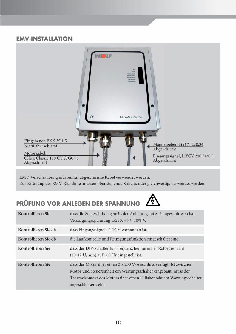
EMV-INSTALLATION
EMV-Verschraubung müssen für abgeschirmte Kabel verwendet werden.Zur Erfüllung der EMV-Richtlinie, müssen obenstehende Kabeln, oder gleichwertig, verwendet werden.
Eingehende EKK 3G1,5Nicht abgeschirmtMotorkabel,Ölfl ex Classic 110 CY, /7G0,75Abgeschirmt
Magnetgeber, LiYCY 2x0,34AbgeschirmtEingangssignal, LiYCY 2x0,34/0,5Abgeschirmt
PRÜFUNG VOR ANLEGEN DER SPANNUNG
Kontrollieren Sie dass die Steuereinheit gemäß der Anleitung auf S. 9 angeschlossen ist. Versorgungsspannung 1x230, +6 / -10% V.
Kontrollieren Sie ob dass Eingangssignale 0-10 V vorhanden ist.
Kontrollieren Sie ob die Laufk ontrolle und Reinigungsfunktion eingeschaltet sind.
Kontrollieren Sie dass der DIP-Schalter für Frequenz bei normaler Rotordrehzahl (10-12 U/min) auf 100 Hz eingestellt ist.
Kontrollieren Sie dass der Motor über einen 3 x 230 V-Anschluss verfügt. Ist zwischen Motor und Steuereinheit ein Wartungsschalter eingebaut, muss der Th ermokontakt des Motors über einen Hilfskontakt am Wartungsschalter angeschlossen sein.
10
11
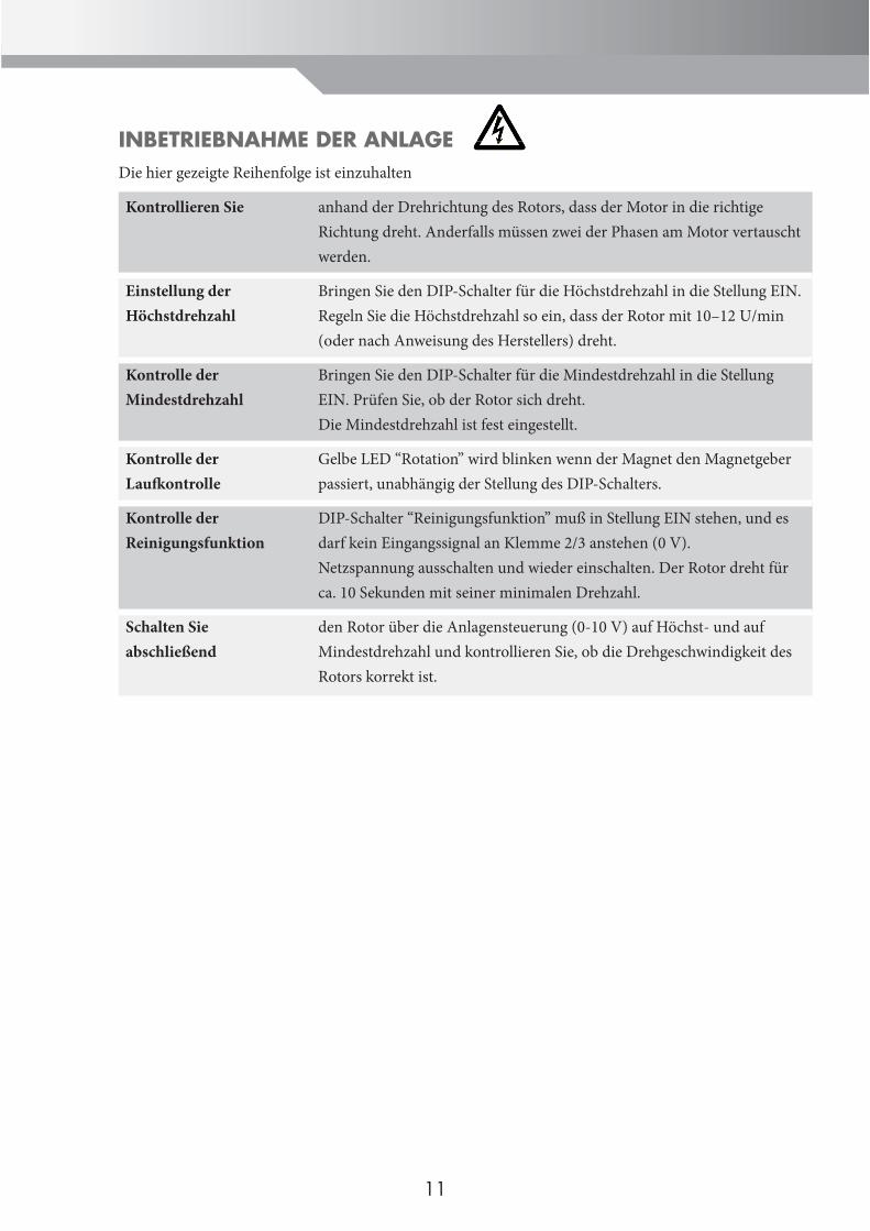
INBETRIEBNAHME DER ANLAGEDie hier gezeigte Reihenfolge ist einzuhalten
Kontrollieren Sie anhand der Drehrichtung des Rotors, dass der Motor in die richtige Richtung dreht. Anderfalls müssen zwei der Phasen am Motor vertauscht werden.
Einstellung der Höchstdrehzahl
Bringen Sie den DIP-Schalter für die Höchstdrehzahl in die Stellung EIN.Regeln Sie die Höchstdrehzahl so ein, dass der Rotor mit 10–12 U/min (oder nach Anweisung des Herstellers) dreht.
Kontrolle derMindestdrehzahl
Bringen Sie den DIP-Schalter für die Mindestdrehzahl in die Stellung EIN. Prüfen Sie, ob der Rotor sich dreht. Die Mindestdrehzahl ist fest eingestellt.
Kontrolle der Laufk ontrolle
Gelbe LED “Rotation” wird blinken wenn der Magnet den Magnetgeber passiert, unabhängig der Stellung des DIP-Schalters.
Kontrolle derReinigungsfunktion
DIP-Schalter “Reinigungsfunktion” muß in Stellung EIN stehen, und es darf kein Eingangssignal an Klemme 2/3 anstehen (0 V).Netzspannung ausschalten und wieder einschalten. Der Rotor dreht für ca. 10 Sekunden mit seiner minimalen Drehzahl.
Schalten Sie abschließend
den Rotor über die Anlagensteuerung (0-10 V) auf Höchst- und auf Mindestdrehzahl und kontrollieren Sie, ob die Drehgeschwindigkeit des Rotors korrekt ist.
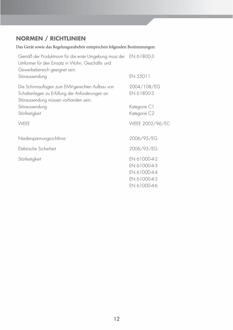
NORMEN / RICHTLINIENDas Gerät sowie das Regelungszubehör entsprechen folgenden Bestimmungen:
Gemäß der Produktnorm für die erste Umgebung muss der Umformer für den Einsatz in Wohn, Geschäfts- und Gewerbebereich geeignet sein. Störaussendung
EN 61800-3
EN 55011
Die Schirmaufl agen zum EMV-gerechten Aufbau von Schaltanlagen zu Erfüllung der Anforderungen an Störaussendung müssen vorhanden sein.StöraussendungStörfestigkeit
2004/108/EGEN 61800-3
Kategorie C1Kategorie C2
WEEE WEEE 2002/96/EC
Niederspannungsrichtlinie 2006/95/EG
Elektrische Sicherheit 2006/95/EG
Störfestigkeit EN 61000-4-2EN 61000-4-3EN 61000-4-4EN 61000-4-5EN 61000-4-6
12
EIGENE NOTIZEN
13

11
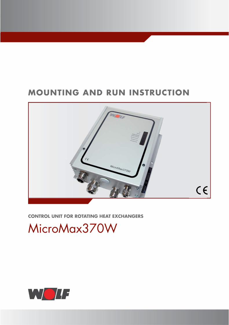
MOUNTING AND RUN INSTRUCTION
CONTROL UNIT FOR ROTATING HEAT EXCHANGERS
MicroMax370W
SAFETY REFERENCEIn this description theese following symbols and reference signs will be used. Th eese important directions concerns the personal protection and the technical safety of run.
“Safety reference” characterize directions, which is precisely to avoid risks or injury of people and to prevent damage of the equipment.
Danger! Electric voltage on electrical components!Attention: Before removing the cover, disconnect the operating switch.
Never take hold of connected operating switch at electric components and contacts. Risk of impulse with healthrisk or death as result.
Th e connecting terminals still has voltage on even aft er disconnecting the operating switch.
“Reference” characterize technical directions, that should be noticed, to prevent damage and funktion disturbance of the equipment.Attention
16
Installation / Putting into operation
- Th e installation and start up procedure of the wheel arrangement and the connected accessories must according to DIN EN 50110-1 be performed only by specialist workers.- Th e local EVU-regulations and the VDE-directions are to be observed.- DIN VDE 0100. Regulations for the establishment of high voltage system up to 1000V.- DIN VDE 0105-100. Run of electrical installations abroad. Th e ÖVE-instructions as well as the local building regulations are applied in Austria.
Warning indication - The removal, by-passing or invalidation from the safety and control system is forbidden!- The equipment must be driven only in perfect technical condition. Disturbance and damage, that affect the safety, must immidiately be eliminated.
Maintenance / Repair - Th e impeccable function of the electrical equipment should be controlled at regular intervals.- Disturbance and damage must be redressed only by specialist workers.- Defected components must be replaced only by original Wolf-spares.- Prescribed electrical protection values are to be observed. (See technical data).
If technical changes of the Wolf-regulations are made, we do not apply for any warranty of the damage described here.
Disposal and Recycling For disposal of damaged system componenst or its system aft er product lifetime please consider the following advice:
Dispose properly, seperated into material groups they belong to.Th e goal should always be a maximal possible reuseability of the raw material with least possible environmental burden.
Never throw electric or electronic scrap in the garbage, use the appropriate collection points.
Always dispose as environmentally safe, as the technic of the environment protection, recycling and disposal corresponds to.
INSTALLATION DIRECTIONS
Attention
17
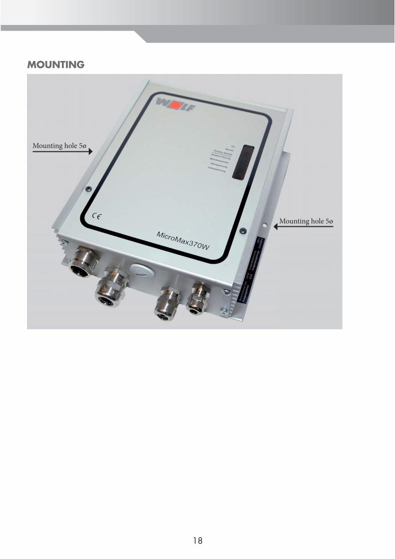
MOUNTING
Mounting hole 5ø
Mounting hole 5ø
18
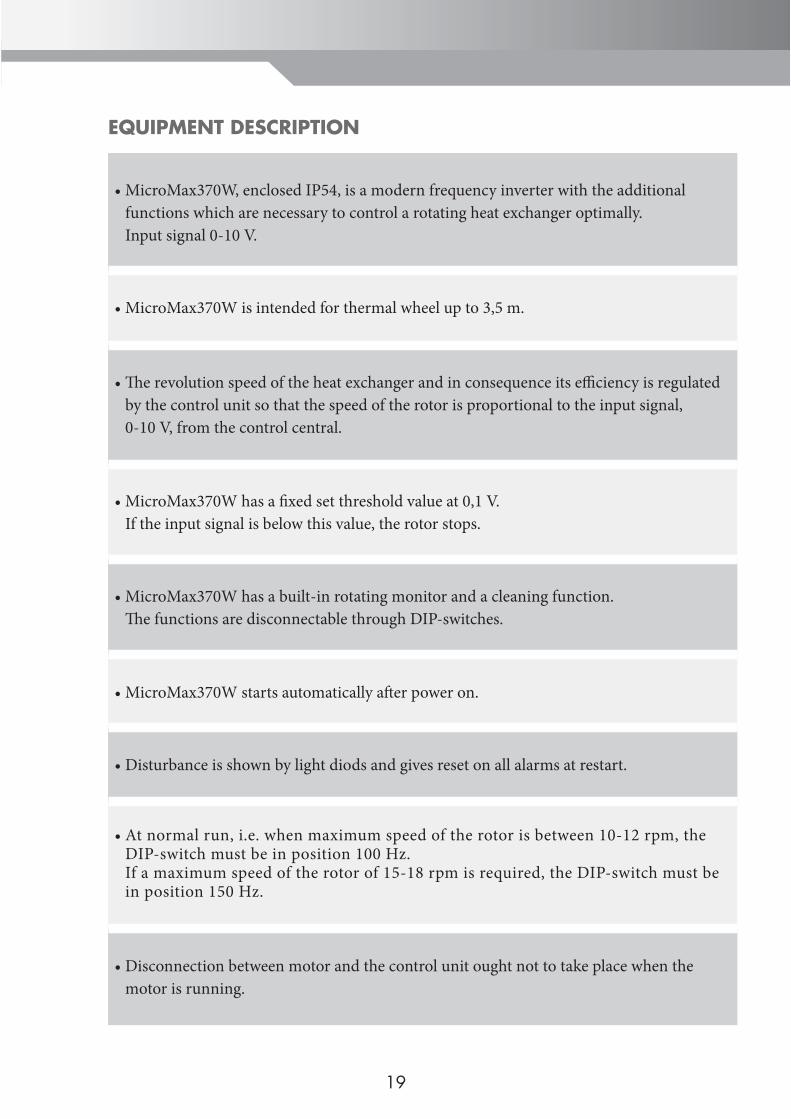
MicroMax370W, enclosed IP54, is a modern frequency inverter with the additional functions which are necessary to control a rotating heat exchanger optimally. Input signal 0-10 V.
•
MicroMax370W is intended for thermal wheel up to 3,5 m. •
Th e revolution speed of the heat exchanger and in consequence its effi ciency is regulated by the control unit so that the speed of the rotor is proportional to the input signal, 0-10 V, from the control central.
•
MicroMax370W has a fi xed set threshold value at 0,1 V. If the input signal is below this value, the rotor stops.
•
MicroMax370W has a built-in rotating monitor and a cleaning function.Th e functions are disconnectable through DIP-switches.
•
MicroMax370W starts automatically aft er power on.•
Disturbance is shown by light diods and gives reset on all alarms at restart.•
At normal run, i.e. when maximum speed of the rotor is between 10-12 rpm, the DIP-switch must be in position 100 Hz.If a maximum speed of the rotor of 15-18 rpm is required, the DIP-switch must be in position 150 Hz.
•
Disconnection between motor and the control unit ought not to take place when the motor is running.
•
EQUIPMENT DESCRIPTION
19
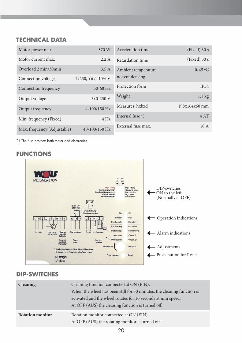
TECHNICAL DATA
FUNCTIONS
DIP-SWITCHES
Cleaning Cleaning function connected at ON (EIN). When the wheel has been still for 30 minutes, the cleaning function is activated and the wheel rotates for 10 seconds at min speed. At OFF (AUS) the cleaning function is turned off .
Rotation monitor Rotation monitor connected at ON (EIN). At OFF (AUS) the rotating monitor is turned off .
Acceleration time (Fixed) 30 s
Retardation time (Fixed) 30 s
Ambient temperature,not condensing
0-45 ºC
Protection form IP54
Weight 1,1 kg
Measures, hxbxd 198x164x60 mm
Internal fuse *) 4 AT
External fuse max. 10 A
Motor power max. 370 W
Motor current max. 2,2 A
Overload 2 min/30min 3,5 A
Connection voltage 1x230, +6 / -10% V
Connection frequency 50-60 Hz
Output voltage 3x0-230 V
Output frequency 4-100/150 Hz
Min. frequency (Fixed) 4 Hz
Max. frequency (Adjustable) 40-100/150 Hz
*) The fuse protects both motor and electronics
20
Push-button for Reset
DIP-switchesON to the left (Normally at OFF)
Operation indications
Alarm indications
Adjustments
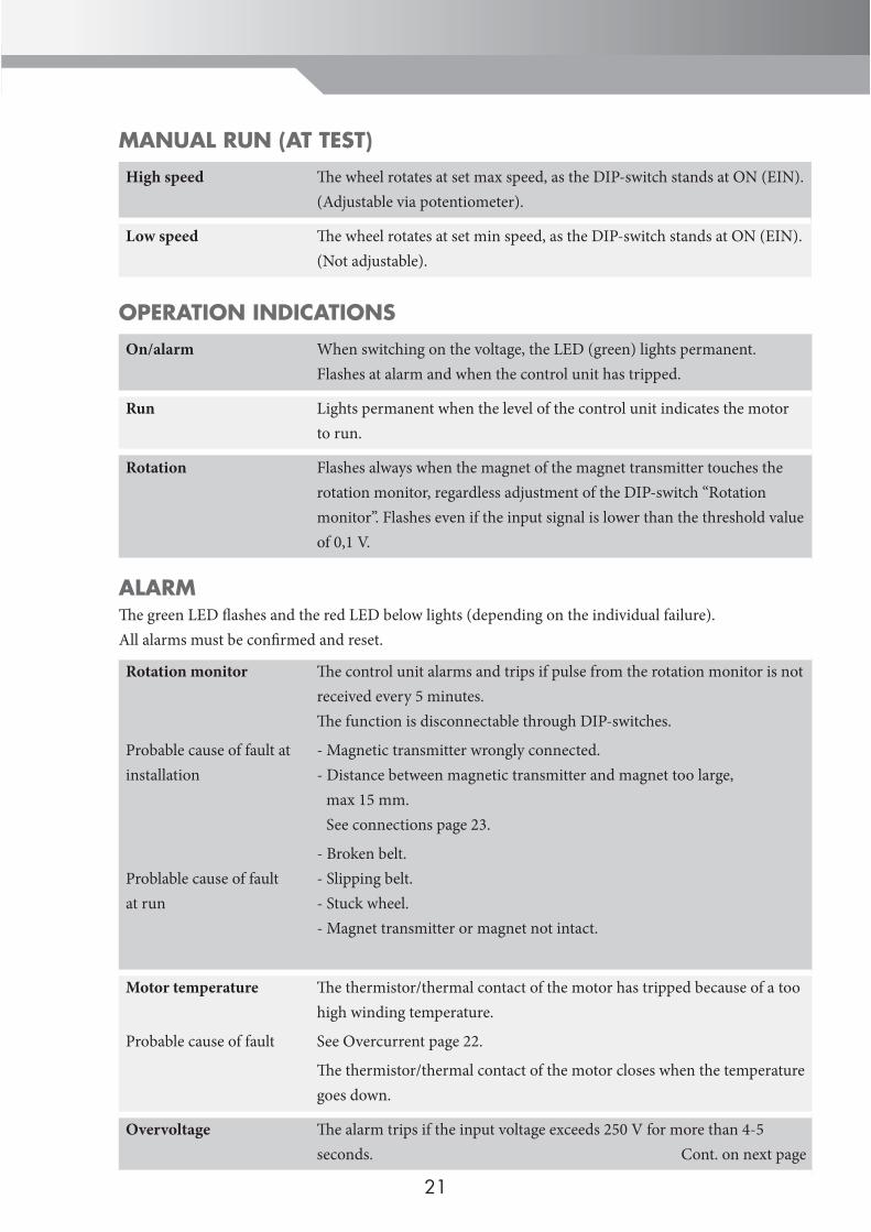
MANUAL RUN (AT TEST)
High speed Th e wheel rotates at set max speed, as the DIP-switch stands at ON (EIN). (Adjustable via potentiometer).
Low speed Th e wheel rotates at set min speed, as the DIP-switch stands at ON (EIN). (Not adjustable).
OPERATION INDICATIONS
On/alarm When switching on the voltage, the LED (green) lights permanent. Flashes at alarm and when the control unit has tripped.
Run Lights permanent when the level of the control unit indicates the motor to run.
Rotation Flashes always when the magnet of the magnet transmitter touches the rotation monitor, regardless adjustment of the DIP-switch “Rotation monitor”. Flashes even if the input signal is lower than the threshold value of 0,1 V.
ALARMTh e green LED fl ashes and the red LED below lights (depending on the individual failure). All alarms must be confi rmed and reset.
Rotation monitor
Probable cause of fault at installation
Problable cause of fault at run
Th e control unit alarms and trips if pulse from the rotation monitor is not received every 5 minutes.Th e function is disconnectable through DIP-switches.
- Magnetic transmitter wrongly connected.- Distance between magnetic transmitter and magnet too large, max 15 mm. See connections page 23.
- Broken belt.- Slipping belt. - Stuck wheel. - Magnet transmitter or magnet not intact.
Motor temperature
Probable cause of fault
Th e thermistor/thermal contact of the motor has tripped because of a too high winding temperature.
See Overcurrent page 22.
Th e thermistor/thermal contact of the motor closes when the temperature goes down.
Overvoltage Th e alarm trips if the input voltage exceeds 250 V for more than 4-5 seconds. Cont. on next page
21
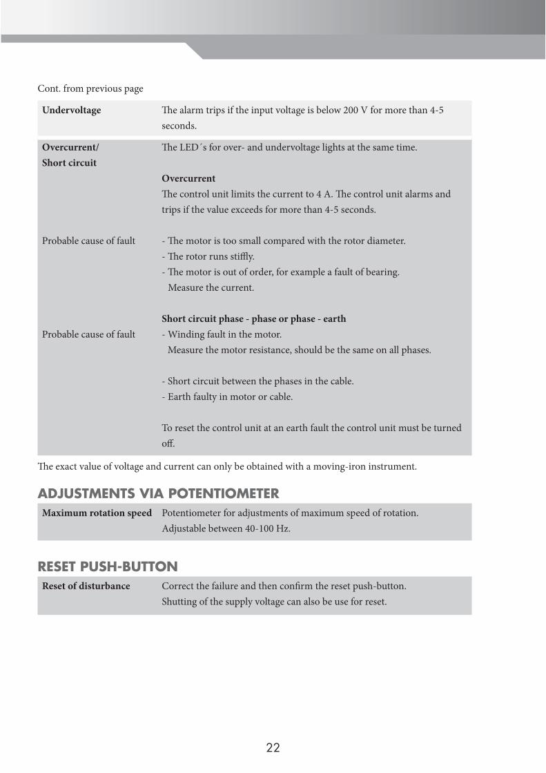
Cont. from previous page
Undervoltage Th e alarm trips if the input voltage is below 200 V for more than 4-5 seconds.
Overcurrent/Short circuit
Probable cause of fault
Probable cause of fault
Th e LED´s for over- and undervoltage lights at the same time.
OvercurrentTh e control unit limits the current to 4 A. Th e control unit alarms and trips if the value exceeds for more than 4-5 seconds.
- Th e motor is too small compared with the rotor diameter.- Th e rotor runs stiffl y.- Th e motor is out of order, for example a fault of bearing. Measure the current.
Short circuit phase - phase or phase - earth- Winding fault in the motor. Measure the motor resistance, should be the same on all phases.
- Short circuit between the phases in the cable.- Earth faulty in motor or cable.
To reset the control unit at an earth fault the control unit must be turned off .
Th e exact value of voltage and current can only be obtained with a moving-iron instrument.
ADJUSTMENTS VIA POTENTIOMETERMaximum rotation speed Potentiometer for adjustments of maximum speed of rotation.
Adjustable between 40-100 Hz.
RESET PUSH-BUTTONReset of disturbance Correct the failure and then confi rm the reset push-button.
Shutting of the supply voltage can also be use for reset.
22
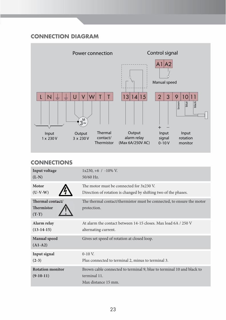
CONNECTION DIAGRAM
CONNECTIONSInput voltage(L-N)
1x230, +6 / -10% V.50/60 Hz.
Motor(U-V-W)
Th e motor must be connected for 3x230 V.Direction of rotation is changed by shift ing two of the phases.
Th ermal contact/Th ermistor(T-T)
Th e thermal contact/thermistor must be connected, to ensure the motor protection.
Alarm relay(13-14-15)
At alarm the contact between 14-15 closes. Max load 6A / 250 V alternating current.
Manual speed(A1-A2)
Gives set speed of rotation at closed loop.
Input signal(2-3)
0-10 V.Plus connected to terminal 2, minus to terminal 3.
Rotation monitor(9-10-11)
Brown cable connected to terminal 9, blue to terminal 10 and black to terminal 11.Max distance 15 mm.
23
A1 A2
Manual speed
T T 2 3
+Inputsignal0-10 V
9 10
Inputrotationmonitor
3~
L N U V W
M
Input1 x 230 V
Output3 x 230 V
Thermalcontact/
Thermistor
13 14 15
Outputalarm relay
(Max 6A/250V AC)
brow
n
blue
11
blac
k
Power connection Control signal
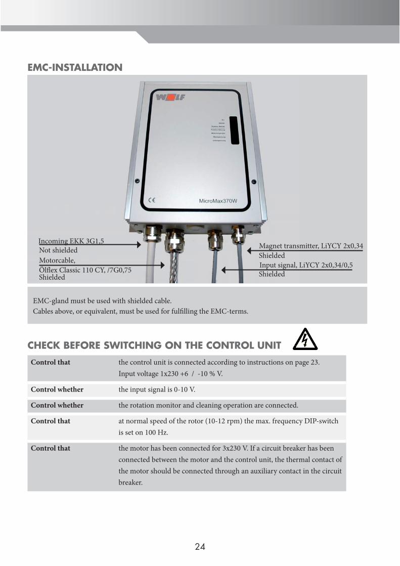
EMC-gland must be used with shielded cable. Cables above, or equivalent, must be used for fulfi lling the EMC-terms.
Incoming EKK 3G1,5Not shieldedMotorcable,Ölfl ex Classic 110 CY, /7G0,75Shielded
Magnet transmitter, LiYCY 2x0,34ShieldedInput signal, LiYCY 2x0,34/0,5Shielded
EMC-INSTALLATION
CHECK BEFORE SWITCHING ON THE CONTROL UNIT
Control that the control unit is connected according to instructions on page 23.Input voltage 1x230 +6 / -10 % V.
Control whether the input signal is 0-10 V.
Control whether the rotation monitor and cleaning operation are connected.
Control that at normal speed of the rotor (10-12 rpm) the max. frequency DIP-switch is set on 100 Hz.
Control that the motor has been connected for 3x230 V. If a circuit breaker has been connected between the motor and the control unit, the thermal contact of the motor should be connected through an auxiliary contact in the circuit breaker.
24
PUTTING THE EQUIPMENT INTO OPERATIONShould be done in order
Control that the motor rotates in the correct direction according to the rotation direction of the wheel. At incorrect rotation direction, two of the phases are shift ing to the motor.
Adjustment of max speed of rotation
Put the DIP-switch for high speed in position ON.Adjust “Max speed” so that the wheel rotates with 10-12 rpm (or according to instructions from the wheel manufacturer).
Control of min speed of rotation
Put the DIP-switch for low speed in position ON.Control that the wheel starts. Th e min speed of rotation is fi xed set.
Control of rotation monitor
Yellow light diode “Rotation” should twinkle when the magnet passes the magnetic transmitter, irrespective of the DIP-switch position.
Control of cleaning function
Th e DIP-switch “cleaning function” must be in position ON and there must not become any input signal at terminal 2/3 (0 V).Turn off the supply voltage and then turn it on. Th e wheel rotates for about 10 seconds with a minimum speed of rotation.
Finish with letting the central control (0-10 V), control the wheel at max- and min speed of rotation and control that the speed of the wheel is correct.
25
STANDARDS / POLICIESBoth the equipment and the regulation appliances correspond to the following regulations:
Standards / Policies
According to the product standard for the fi rst environment, the converter for installation in living, shopping and industry areas must be convenient.Interference emission
EN 61800-3
EN 55011
For the EMC-righteous construction of switchgear and controlgear and to fulfi l the requirements of emission, the shield connections must exist.EmissionImmunity
2004/108/EGEN 61800-3
Category C1Category C2
WEEE WEEE 2002/96/EC
Low voltage policy 2006/95/EG
Electric safety 2006/95/EG
Interference immunity EN 61000-4-2EN 61000-4-3EN 61000-4-4EN 61000-4-5EN 61000-4-6
26
OWN NOTES
27
OWN NOTES
28

Wolf GmbHIndustriestrasse 1D-84048 MainburgTel +49 (0) 8751/74-0 Fax +49 (0) 8751/74-1600www.wolf-heiztechnik.de [email protected]
VERS
ION
1.0
27
44
66
2-D
EGB