Embed Size (px)
Citation preview

DOCUMENT No.: CE*-OML0058-D
MONOSASHI-KUN WITH BRAKE(CE2)
OPERATION MANUAL
PRODUCT NAME : MONOSASHI-KUN WITH BRAKE
MODEL : CE2
○ Read this operation manual carefully to
understand before installation and operation.
○ Pay extra attention on the clause concerning the
safety.
○ Keep this operation manual available whenever
necessary.
SMC CORPORATION

2
Contents Chapter 1: Read Before Use ·························································· 3~8
Chapter 2: Product Summary
2-1. System Configuration ························································ 9~10
2-2. How to Order ········································································ 11
2-2-1. MONOSASHI-KUN with BRAKE ·········································· 11
2-2-2. Options ·········································································· 12
Chapter 3: Selection
Flow Chart to Confirm Utility ············································ 13~14
Chapter 4: Specifications
4-1. Cylinder Specifications ··························································· 15
4-2. Sensor Specifications ····························································· 15
4-3. Cylinder (Brake) Life ······························································ 16
Chapter 5: Wiring
5-1. Connector Wiring Table ·························································· 17
5-2. Wiring for Counter (Controller) ················································· 17
5-3. Wiring for Extension Cable ······················································ 18
5-4. Noise countermeasures ·························································· 19
Chapter 6: Piping
6-1. Example of Recommended Pneumatic ······························· 19~20
6-2. Installation ··········································································· 20
6-3. Air Balance ·········································································· 20
Chapter 7: Structure and Measuring Principle
7-1. Structure ·············································································· 21
7-2. Measuring Principle ······························································· 22
Chapter 8: Brake Mechanism
8-1. Working Principle of Brake Mechanism ······································ 22
8-2. Manually Unlocking································································ 23
8-3. How to change from Unlocked to Locked State ··························· 23
8-4. Holding Force of Locking ························································ 24
8-5. Allowable Kinetic Energy when Locking ······························ 24~25
Specifications are subject to change without prior notice

3
Chapter 1 : Read before Use These safety instructions are intended to prevent a hazardous situation and/or equipment damage. These instructions indicate the level of potential hazard by label of “Caution”, ”Warning”, or ”Danger”. To ensure safety, follow the instructions below as well as ISO/IEC, JIS
*1) and other safety laws
*2).
Caution Operator error could result in injury or equipment damage.
Warning Operator error could result in serious injury or loss of life.
Danger In extreme conditions, there is a possible result of serious injury or
loss of life.
*1) ISO 4414: Pneumatic fluid power - General rules relating to systems
ISO 10218-1: 2006: Robots for industrial environments - Safety requirements - Part 1: Robot
IEC 60204-1: Safety of machinery - Electrical equipment of machines - Part 1:General
requirements
JIS B 8370: General Rules for Pneumatic systems
JIS B 9960-1: Safety of machinery - Electrical equipment of machines - Part 1: General
requirements
JIS B 8433-1:2007: Robots for industrial environments - Safety requirements - Part 1: Robot
*2) Labor Safety and Sanitation Law etc.
Warning
1. The compatibility of pneumatic equipment is the responsibility of the person who designs the pneumatic system or decides its specifications.
Since the products specified here are used in various operating conditions, their compatibility for the specific pneumatic system must be based on specifications or after analysis and/or tests to meet your specific requirements. Ensuring the initial performance and safety are the responsibility of the person who decides the compatibility of the pneumatic system. Pneumatic systems should be constructed after full review of the details of the products other than specifications and possibilities of failures by checking the latest product information.
2. Only trained personnel should operate poneumaticallly operated machinery and equipment. Assembly, handling, or repair of pneumatic systems should be performed by trained and
experienced operators.
3. Do not service machinery/equipment or attempt to remove component until safety is confirmed.
a. Inspection and maintenance of machinery/equipment should only be performed after confirmation
of safe locked-out control positions.
b. When equipment is to be removed, confirm the safety process as mentioned above. Cut the
supply pressure for this equipment and exhaust all residual compressed air in the system.
c. Before machinery/equipment is re-started, take measure to prevent shooting-out of cylinder piston
rod etc.
4. Contact SMC and take necessary safety measures if the products are to be used in any of the following conditions:
a. Conditions and environments beyond the given specifications, or if products are used outdoors.
b. Installation on equipment in conjunction with atomic energy, railway, air navigation, vehicles,
medical equipment, food and beverages, recreation equipment, emergency stop circuits, press
applications, or safety equipment.
c. An application which has the possibility of having negative effects on people, property, or animals,
requiring special safety analysis.
d. When used in an interlock circuit, dual interlock such as mechanical protection is necessary in
case of accident. Periodical inspection is also necessary to confirm proper operation.
!
!
!
!

4
Operating and Storage Environments
Warning
1. Envionments to avoid
Avoid using or storing the products in the
following environments which may cause
failures.
If the products need to be used or stored in
those environments, take necessary measures.
a. Place where ambient temperature exceeds
the range of 0℃ to 50℃.
b. Place where ambient humidity exceeds the
range of 35% to 85% RH.
c. Place where condensation occurs due to
sudden temperature change.
d. Place where atmosphere containing corrosive
gas, flammable gas or organic solvent.
e. Place where atmosphere containing
con-ductive powder such as dust and iron
chips, oil mist, salt, or organic solvent, or
splashing cutting chips, dust and cutting oil
(water , liquid) over the products.
f. Place where the products are exposed to
direct sunlight or radiated heat.
g. Place where strong electromagnetic noise is
generated (place where strong electric field,
strong magnetic field or surge is generated).
h. Place where static electricity is discharged or
condition that the products have electrostatic
discharge.
i. Place where strong high frequency is
gene-rated.
j. Place where damages of thunder are
expected.
k. Place where vibration or impact is directly
given to the products.
l. Condition that the products are deformed by
force or weight applied.
2. Do not close any objects which are affected
by magnets.
Since magnets are built in cylinders, do not close
magnetic disks, magnetic cards or magnetic
tapes. The data may be destroyed.
Precaution on Design Warning
1. There is a possibility of dangerous sudden
action by cylinders if sliding parts of
machi-nery are twisted due to external forces,
etc.
In such cases, human injury may occur; e. g., by
catching hands or feet in the machinery, or
damage to the machinery itself may occur.
2. Provide a cover to minimize the risk of
human injury.
When a driven object or moving parts of a
cylinder may cause the risk of human injury,
design a structure to avoid contact with human
body.
3. Securely tighten all stationary parts and
connected parts of cylinders so that they will
not become loose.
Tighten cylinders securely especially when they
are used in high frequency or in locations where
direct vibration or impact shock, etc. will be
applied to the body of the cylinder.
4. Deceleration circuits or shock absorbers are
needed in some cases.
If a driven object travels at a high speed or is
heavy, impact will not be sufficiently absorbed
only with the cylinder cushion. In such cases,
use a circuit to decelerate the cylinder speed
before the cushion becomes effective or use
external shock absorbers to reduce impact. At
this time, take the rigidity of machinery into
account.
5. Consider possible drop of pressure in circuit
due to power outage.
For cylinders used in clamping mechanism, a
work may become loose due to less clamping
force by pressure drop in circuit at the time of
power outage. Install safety devices to prevent
human injury and machinery damage. Measures
should be taken to prevent drop of hanging or
lifing equipment.
6. Consider possible loss of power sources.
Measures should be taken to protect against
human injury and machinery damage in the
event that there is a loss of air pressure,
electricity or hydraulic power.
7. Design circuit to prevent shooting out of a
driven object.
A driven object is quickly shot out when pressure
is supplied from one side of the piston after air in
the cylinder is exhausted in such cases that
cylinder is actuated by exhaust center type of
directional control valve or started after residual
air is exhausted from the circuit. At this time,
human injury may occur; e.g., by catching hands
or feet in the machinery, or damage to the
machinery itself may occur. Therefore, the
machine should be designed and constructed to
prevent shooting out.
!
!

5
8. Consider emergency stops.
Design the machinery so that human injury
and/or damage to machinery and equipment will
not be caused when machinery is stopped by a
safety device under abnormal conditions, a
power outage or a manual emergency stop.
9. Consider actions when operation is restarted
after an emergency stop or abnormal stop.
Design the machinery so that human injury or
equipment damage will not occur upon restart of
operation. When the cylinder is required to return
to the initial position, provide the equipment with
a safe override.
10.Construct the machinery so that moving
objects and the moving parts of the cylinder
with brake do not come into direct contact with
the human body.
11.Use a balanced circuit in which lurching of the
cylinder is prevented. When operation is locked
in specified intermediate positions of the stroke,
and air pressure is applied to only one side of
the cylinder, the piston will lurch when the lock
is released. This might cause injury or damage
to machinery.
Selection Warning
1. Confirm the specifications.
The product in this manual is designed to be
used only in industrial compressed air system.
The product should not be used with pressures
or temperatures outside the range of the
specifications, as this may cause damage or
malfunction, etc.
2. Intermediate stop
When cylinder piston is stopped intermediately
by 3-position closed center type of directional
control valve, intermediate stop positions may
not be as precise and exact as hydraulic
operation due to compressibility of air. Valves
and cylinders are not guaranteed for zero air
leakage, and stop position may not be held in a
long period of time. Consult SMC for long term
holding of stop positions.
3. When a cylinder is in a no-load and locked state,
the holding force (maximum static load) is the
lock’s ability to hold a static load that does not
involve vibrations or shocks. To ensure braking
force, the maximum load must be set as described
below.
①For constant static loads, such as for drop
prevention:
35% or less of holding force (Maximum static
load)
Note) For applications such as drop prevention,
consider situations in which the air source
is shut off, and make selections based on
the holding force of the spring locked
state. Do not use the pneumatic lock for
drop prevention purposes.
②When kinetic energy acts upon the cylinder,
such as when effecting an intermediate stop,
there are constraints in terms of the allowable
kinetic energy that can be applied to the
cylinder in a locked state. Refer to the
allowable kinetic energy of the respective
series. Furthermore, during locking, the
mechanism must sustain the thrust of the
cylinder itself, in addition to absorbing the
kinetic energy. Therefore, even within a given
allowable kinetic energy level, there is an
upper limit to the amount of the load that can
be sustained.
- Maximum load for horizontal mounting: 70%
or less of the holding force (Maximum
static load) for spring lock
- Maximum load for vertical mounting: 35% or
less of the holding force (Maximum static
load) for spring lock
③In a locked state, do not apply impact, strong
vibrations or rotational forces. Any impact,
strong vibrations or rotational forces from
external sources could damage or shorten
the life of the lock unit.
④Although the cylinder can be locked in both
directions, be aware that its holding force is
smaller in one of the directions. Holding
force at piston rod extended side is approx.
15% less.
Caution 1. Mount speed controller and adjust cylinder
operation speed gradually from low speed to
a desired speed.
Air Supply Warning
1. Do not use the product out of the specified
ranges for pressure and temperature to
pre-vent equipment damage and
mal-function.
!
!
!

6
①Operating pressure:
Actuating part: 0.1 – 1.0MPa
Braking part: 0.3 – 0.5MPa
②Fluid & ambient temperature: 0 to 60C
2. Use clean air.
Do not use the product with compressed air
includes chemicals, synthetic materials
(including organic solvents), salinity, corrosive
gases, etc., as this may cause damage or
malfunction.
Caution
1. Install air filter.
Install air filter before and in vicinity of valve. The
filter should be able to collect particles of 5
microns or smaller. A large quantity of drain may
cause malfunction of pneumatic components.
2. Install after cooler, air dryer, auto drain, etc.
Compressed air that includes excessive
condensate may cause malfunction of valve and
other pneumatic equipment. To prevent this,
install after cooler, air dryer, auto drain, etc.
Pneumatic circuit
Warning
1. Be certain to use a pneumatic circuit which will
apply balanced pressure to both sides of the
piston when in a locked stop. (Refer to Chapter 6
for recommended pneumatic circuit.)
In order to prevent the cylinder lurching after a
locked stop, use a circuit which applies balanced
pressure to both sides of the piston when restarting
or when manually releasing the lock, thereby
canceling the force generated by the load in the
direction of piston movement.
2. Use a solenoid valve for unlocking which has a
larger effective area, as a rule 50% or more of
the effective area of the cylinder drive solenoid
valve.
(Refer to Chapter 6 for recommended
pneumatic components.)
The larger the effective area is, the shorter
the locking time will be, and stopping
accuracy will be improved.
3. Place the solenoid for unlocking close to the
cylinder, and no farther than the cylinder drive
solenoid valve.
The shorter the distance from the cylinder, the
shorter the overrun amount will be, and stopping
accuracy will be improved.
4. Allow at least 0.5 seconds from a locked stop
(intermediate stop of the cylinder) until release of
the lock.
When the locked stop time is too short, the
piston rod may lurch at a speed greater than the
control speed of the speed controller.
5. When restarting, control the switching signal for
the unlocking solenoid valve so that it acts before
or at the same time as the cylinder drive solenoid
valve.
If the signal is delayed, the piston rod may lurch at
a speed greater than the control speed of the
speed controller.
Installation
Warning
1. Connect the rod end and the load with the lock
released.
2. Ensure that the equipment operates properly
before the use.
3. Operation manual
Do not install the products unless the safety
instruction have been read and understood.
Keep this operation manual on file for future
reference.
Caution
1. Maintenance space
When installing the products, allow space for
maintenance.
2. Installation of jigs
When hardware and nuts are screwed into the
piston rod end, the piston rod should be fully
retracted.
Use double nuts to fix a work since Precision
MONOSASHI-KUN (Scale Reading Cylinder)
does not have any parallel parts at the rod.
3. Do not give strong impact and/or excessive
moment when work is mounted.
External force other than allowable moment may
cause rattle at guide part and/or increase in
sliding resistance.
4. Use the product in such a condition that load
is always applied in the axial direction of the
piston rod.
When load is applied in other directions than
cylinder axial direction, regulate the load itself
by the guide.
Perform a complete centering when cylinder is
mounted.
5. Be careful to avoid scratches or dents, etc. on
the sliding sections of the piston rod.
!
!
!
!

7
Wiring
Warning
1. Preparation for wiring
Shut off the power before wiring (including
insertion and removal of connectors). Mount a
protective cover on the terminal block after
wiring.
2. Check the power
Make sure the power has sufficient capacity and
voltages are within the specified range before
wiring.
3. Grounding
Ground terminal block F.G. (Frame Ground).
Do not ground it with devices generating strong
electromagnetic noise.
4. Check wiring
Incorrect wiring may cause damage or
malfunction of the products. Make sure the
wiring is correct before operation.
Caution
1. Separation of signal wires from power wire
Avoid common or parallel wiring of signal and
power wires to prevent malfunction due to noise.
2. Wiring arrangement and fixation
Avoid bending cables sharply at connector part
or electrical entry in wiring arrangement.
Inproper arrangement may cause disconnection
which in turn causes malfunction. Fix cables
close enough not to give excessive force to the
connector.
Piping Caution
1. Before piping
Remove cutting chips, cutting oil, dust, etc. in
piping by flushing or cleaning before piping.
Care should be taken especially that any cutting
chips, cutting oil, dust, etc. do not exist after a
filter.
2. At piping
①Foreign matter should not enter. Entering of
foreign matter will cause malfunction.
②Cutting chips and sealing materials at piping
threads should not enter valves when piping
and fittings are screwed in. Leave 1.5 to 2
threads when seal tape is used.
Lubrication Caution
1. Lubrication of cylinder
①This cylinder is pre-lubricated and can be used
without lubrication.
②In case of lubrication, use a equivalent of the
turbine oil type 1 ISO VG32. Once lubrication
is performed, it should be continued since the
initial lubricant flows out causing malfunction.
Adjustment
Caution
1. The locks are manually disengaged when the
cylinder is shipped from the factory. Be sure to
change them to the locked state before using
the cylinder.
2. Adjust the cylinder’s air balance. In the state in
which a load is attached to the cylinder,
disengage the lock and adjust the air pressure
on the rod side and the head side of the
cylinder to obtain a load balance. By
maintaining a proper air balance, the piston rod
can be prevented from lurching when the lock is
disengaged.
3. Adjust the mounting position of detection
devices such as autoswitches.
Sensor unit
Caution 1. Do not remove the sensor unit.
The position and sensitivity of the sensor is
adjusted properly before shipment.
Removing or replacing the sensor may cause
malfunction.
2. Operate the system with an external magnetic
field of 14.5mT or less.
Strong magnetic field in the vicinity may cause
malfunction, since CE2 sensor is magnetic
type.
This is equivalent to a magnetic field of
approximately 18cm in radius from a welding
area using a welding current of almost 15,000
amperes. To use the system in a magnetic field
that exceeds this value, use a magnetic material
to shield the sensor unit
!
!
!
!
!
!

8
3. Do not pull sensor cable strongly.
Such action may cause failure.
4. Water shall be kept away from the sensor unit to
avoid failure. (IP65 Protection)
5. Power supply line
Do not mount any switch or relay to power
supply line (12 VDC to 24 VDC).
Measurement
Caution SMC products are not intended for use as
instruments for legal metrology.
Measurement instruments that SMC manufactures
or sells have not been qualified by type approval
tests relevant to the metrology (measurement) laws
of each country. Therefore, SMC products cannot
be used for business or certification ordained by the
metrology (measurement) laws of each country.
Maintenance and Check
Warning
1. Performing regular check
Check regularly that the products do not operate
with failures unsolved. Check should be done
by trained and experienced operators.
2. Dismantling of product and supply/exhaust
of compressed air.
Before dismantling, ensure that drop preventing
and runaway preventing treatments are properly
provided, shut the power source of air supplied,
and exhausts compressed air in the system.
When starting operation again, operate the
product with care after ensuring that a treatment
for preventing extrusion is properly provided.
3. Prohibition of disassembly and modification
To prevent accidents such as failures and
electric shocks, do not remove the cover to
perform disassembly or modification. If the
cover has to be removed, shut off the power
before removal.
4. Disposal
Request a special agent for handling industrial
waste to dispose the products.
!
Operating range
Welding machine
!

9
Chapter 2: Product Summary
The Stroke Reading Cylinder (CE2 series) is an air cylinder that has a brake (lock) function and scaling
function. Multiple positioning is available by using in combination with a specified controller (CEU2
series), and dimension measurement and simple positioning, and safety lock are available by using in
combination with a counter (CEU1 or CEU5 series).
The braking function employs a lock system using both spring and air pressure. The magnetic scale
on the piston rod is read by a magnet sensor. The resolution is 0.1mm.
2-1 System Configuration
・CE2 + CEU2
The brake valve and the actuation valve are controlled by the specified controller, CEU2, for multiple
positioning. ⇒ Refer to operation manual of CEU2 for details.
・Prediction control and learning control achieve positioning with high repeatability.
・Retry function automatically corrects stopping position.
Wiring with external equipment (Incl. sequencer)
Controller (CEU2)
CE2 (Stroke reading cylinder with brake) Extension cable
(CE1-R)
Actuating
Valve
Brake
valve

10
・CE2 + CEU1 (or CEU5)
Suitable for simple positioning systems, and systems which require safety during measurement.
⇒ Refer to the operation manuals of CEU1 (Preset counter) and CEU5 (Multi-counter) for
details.
・Operation only with actuation valve is available by manual lock release.
External
equipment
(Sequencer)
CE2 (Stroke reading cylinder with brake) Extension cable
(CE1-R)
Brake
valve
Actuating
Valve

11
2-2 How to Order
2-2-1 Stroke Reading Cylinder with brake
CE2 B 40 - 100 ※ ※ ※- ※ ※
Mounting Type Autoswitch suffix
B Double end tapped Autoswitch type
L Foot type (See below)
F Front flange type Connector
G Rear flange type Nil With connector
C Single clevis type Z No connector
D Double clevis type Cushion
T Center trunnion type Nil Double side cushion
N Without cushion
Bore size R Rod cushion
40 40mm Stroke (mm) H Head cushion
50 50mm (See below) Bellows
63 63mm Nil No bellows
80 80mm J Nylon tarpaulin
100 100mm K Heat resistant tarpaulin
Bore size (mm) Std. stroke
No bellows With bellows
40 25 to 850 25 to 700
50 25 to 800 25 to 650
63 25 to 800 25 to 650
80 25 to 750 25 to 600
100 25 to 750 25 to 600
Applicable autoswitch types
Refer to the autoswitch catalog for details.
Bore size (mm) Available stroke (RFS)
No bellows With bellows
40 To 1200 To 950
50 To 1150 To 900
63 To 1150 To 900
80 To 1100 To 900
100 To 1100 To 850
Autoswitch suffix (qty.)
Nil 2 pcs.
S 1 pc.
n n pcs.

12
2-2-2 Options
Controller
CEU2※
Output transistor type
Nil NPN open collector output
P PNP open collector output
CE1-ROOC CE1-RO5
CE1-R10
CE1-R15
CE1-R20
CE1-R*C
3-Points Preset Counter Multi Counter
CEU1※-※ CEU5※※-※
Supply voltage Supply voltage
Nil 80 to 120VAC Nil 100 to 240VAC
D DC24V Base part D DC24V
Output transistor type number Output to PC/PLC
Nil NPN Open collector Nil RS-232C
P PNP Open collector B RS-232C+BCD
Output transistor type
Nil NPN Open collector
P PNP Open collector
Extension Cable
CE1-R※※
Connector *1)
Nil Extension cable
C Extension cable & connector(CE1-R00C)
Cable Length
05 5m
10 10m
15 15m
20 20m
*1) A female connector is attached to one end of the extension cable.
The male connector which is attached if symbol C is selected is the same connector (CE2**-*Z) used for the
cable terminal of the stroke reading cylinder with brake (CE2).
Connector Extension cable

13
Chapter 3: Selection
Flow Chart to Confirm Utility
100 100 300 200 400
500
ヒ ゚ ス ト ン 速度(mm/s)
垂直取付の場合
B e g i n n i n g
I s t h e c y l i n d e r’s k i n e t i c e n e r g y
Wi t h i n t h e a l l o w a b l e r a n g e ?
I s t h e s p e e d w i t h i n t h e
g i v e n r a n g e i n t h e
d i a g r a m ? A n d , w i t h i n
s p e c i f i c a t i o n s ?
A r e t h e r e a n y
m a g n e t i c i n f l u e n c e?
I s c o o l a n t , o i l ,
w a t e r , o r d u s t
p r e s en t ?
I s t h e a n y i n f l u e n c e
o f n o i s e ?
I s i t p o s s i b l e t o t a k e
m e a s u r e s s u c h a s
p r o t e c t i n g t h e c y l i n d e r
w i t h a c o v e r ?
W i l l y o u d o a
p o s i t i o n i n g m o t i o n ?
A
NO
Y E S
Y E S
Y E S
Y E S
NO
NO
NO
D o n o t u s e i t s i n c e i t w i l l
r e s u l t i n a m i s c o u n t .
NO
NO
Y E S
D o e s t h e m o u n t e d l o a d
e x c e e d t h e l o a d g i v e n i n
t h e d i a g r a m ?
Y E S
Y E S
NO
S e l e c t i o n O.K.
NO
NO
Y E S
T h e s y s t e m c a n n o t b e u s e d
b e c a u s e t h e s e e l e m e n t s c o u l d
d a m a g e t h e s e n s o r o r p r o m o t e
t h e d e t e r i o r a t i o n .
Y E S
NO
Y E S
T h e r e i s n o p a r t i c u l a r p r o b l e m i n u s i n g
t h e s y s t e m . R e a d t h e i n s t r u c t i o n m a n u a l
t h o r o u g h l y f o r t h i s i t e m a n d c o u n t e r
( C E U 1 o r C E U 5 ) p r i o r t o o p e r a t i o n .
I s i t p o s s i b l e f o r c a b l e o f
s t r o k e re a d i n g c y l i n d e r t o
b e w i r e d s e p a r a t e l y f r o m
t h e p o w e r l i n e ?
t h e p o w e r l i n e ?
C a n t h e s y s t e m b e
o p e r a t e d b e l o w
1 4 . 5 m T ?
200
100
Lo
ad
w
eig
ht
(k
gf)
200
100
Lo
ad
w
eig
ht
(k
gf)
300 200 400
500
P i s t o n s pe e d (m m/s)
H o r i z o n t a l m o u n t i n g
φ1 0 0
φ80
φ63
φ50
φ40
φ1 0 0
φ63
φ50
φ40
φ80
P i s t o n s p e e d (m m/s)
V e r t i c a l m o u n t i n g
Allowable Kinetic Energy Diagram
Refer to the diagram and select again.

14
YES YES
Is it possible to adopt the recommended pneumatic circuit
in accordance with the cylinder’s mounting orientation?
NO
Is there any fluctuation of pressure, load, or piston speed?
The system cannot be used because it is adversely affected by speed, load, and pressure fluctuations.
NO
YES
NO
Is reaction force or impact force applied during the positioning motion?
A
This system cannot be used because its learning function will not work properly, which may lead to positioning failure
YES
NO
Can the proper air balance be attained in accordance with the cylinder’s
mounting orientation?
Is the minimum setting interval for positioning more than (5mm +
tolerance)?
Is positioning carried out within 30mm from the stroke end?
Is it acceptable if it might run over the target position?
If the position is outside the allowable range, is retry
acceptable?
YES
NO
NO
YES
YES
NO
YES
The system cannot be used because if the proper air balance cannot be attained, an excessive load will be applied to the brake unit.
NO
Positioning cannot be done when the distance is (5mm+tolerance) or less.
NO
Operating conditions will be restricted when positioning is carried out within 30mm from the stroke end. Refer to the instruction manual of the controller for details.
YES
There may be cases of overrun/ retry during the positioning operation. If correction operation is not acceptable, the product cannot be used.
NO
An error might occur if it is set to (number of trial again=0) in order to prevent retry when the position is
outside the allowable range. Is this acceptable?
NO
There is no problem in using the system. Please read this instruction manual and the instruction manual of the controller CEU2 thoroughly before use.
YES
YES
Can the directional control valve be installed separately?
(Manifold is not possible)
Are there any pressure or speed fluctuations associated with the
synchronized movement?

15
Chapter 4: Product Specifications
4-1 Cylinder specifications
Bore size φ40 φ50 φ63 φ80 φ100
Operating fluid Air (Non-lube)
Proof pressure 1.5MPa
Max. operating pressure Actuation pressure : 1MPa Brake pressure 0.5MPa
Min. operating pressure Actuation pressure : 0.1MPa Brake pressure 0.3MPa
Operating piston speed 50 to 500 mm/s Note 1)
Ambient temp. 0 to 60oC (No freezing)
Brake method Spring and pneumatic lock type
Sensor cord length Φ7 to 500mm Oil-resistant
Thread tolerance 6H
Stroke length tolerance ~250mm:+1.0
0、251~1000mm:+1.4
0
Note 1) Be aware of the constraints in the allowable kinetic energy
4-2 Sensor Specifications
Cable φ7.6 core twisted pair shield wire (Oil, heat & flame resistant cable)
Maximum transmission distance
20.5m (when using SMC cable and controller or counter)
Position detection method
Magnetic scale rod / Sensor head <Incremental type>
Magnetic field resistance
14.5mT
Power supply DC10.8V to 26.4V (Power supply ripple : 1% or less)
Current consumption 50mA (Max.)
Resolution 0.1mm/pulse
Accuracy ±0.2mm Note 1)
Output type Open collector (Max.DC30V, 50mA)
Output signal A/B phase difference output
Insulation resistance DC500V, 50MΩ or more (between case and 12E)
Vibration resistance 33.3Hz 6.8G 2hrs. each in X and Y directions 4hrs in Z direction
based upon JIS D1601
Impact resistance 30G 3 times each in X,Y and Z directions
Enclosure IP65 (IEC Standard) Except connector
Extension cable (Option)
5m, 10m, 15m, 20m
Note 1) This includes the digital display error of the controller (CEU2) or counter (CEU1, CEU5).
The overall accuracy after mounting on equipment will vary depending on the mounting
conditions and environment. Therefore, the customer should calibrate the system as a whole.
16
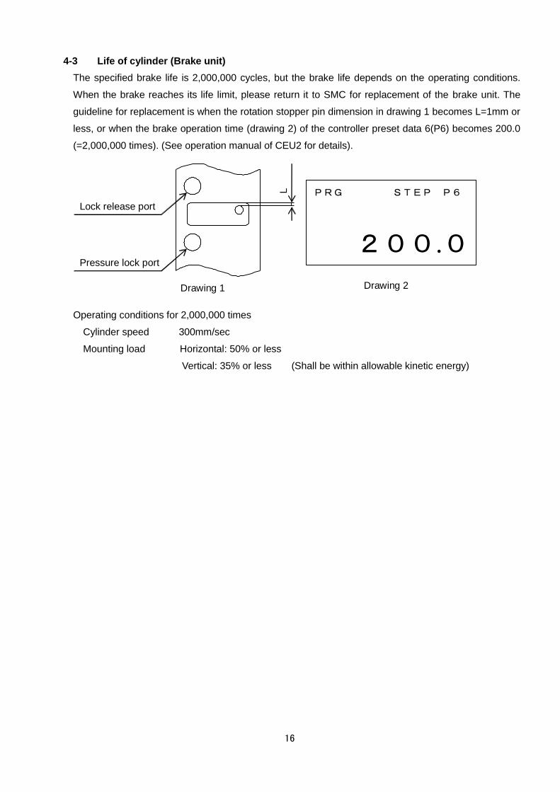
4-3 Life of cylinder (Brake unit)
The specified brake life is 2,000,000 cycles, but the brake life depends on the operating conditions.
When the brake reaches its life limit, please return it to SMC for replacement of the brake unit. The
guideline for replacement is when the rotation stopper pin dimension in drawing 1 becomes L=1mm or
less, or when the brake operation time (drawing 2) of the controller preset data 6(P6) becomes 200.0
(=2,000,000 times). (See operation manual of CEU2 for details).
L
Pressure lock port
Lock release port
Drawing 1
PRG STEP P6
200.0
Drawing 2
Operating conditions for 2,000,000 times
Cylinder speed 300mm/sec
Mounting load Horizontal: 50% or less
Vertical: 35% or less (Shall be within allowable kinetic energy)

17
Chapter 5: Wiring
5-1 Connector Wiring Table
The table below shows combinations of contact mark and wire core color. The connector pin layout
shows the layout of CE2 with connector.
A
B
C
D
E
F
G
H
Connector Pin Layout
Combinations of contact mark and core color
Contact Mark Core Color Signal
A White A-phase
B Yellow B-phase
C Brown COM(0V)
D Blue COM(0V)
E Red 12 to 24VDC
F Black 0V
G Shield Shield
H - Unused
5-2 Wiring for Counter
A
B
COM
COM
+12V
GND
F.G.
CEU1 Sensor input
CEU2
CEU5
Built-in sensor power supply
12VDC, 60mA
680Ω
1kΩ
+12V +12V
1kΩ
+12V
+12V
680Ω
MONOSASHI-KUN with brake
White
Blue
Yellow
Brown
Red
Black
The wiring for CEU* and MONOSASHI-KUN
with brake uses three twisted-pair cables.
Cable with shield

18
5-3 Connection of extension cable
SMC cable CE1-R** shall be used. If the length will be 20m or longer, use specified relay box (Part
no.: CE1-H0374).
*Connection example
*20m or longer
Relay box for sending: Sending box CE1-H0374-1
Relay box for receiving: Receiving box CE1-H0374-2
The part no CE1-H0374 is for a pair of relay boxes for sending and receiving.
(CE1-H0374 consists of CE1-H0374-1 and CE1-H0374-2.)
Caution Operation capability is confirmed at max. transfer distance 20.5m. Do
not use wiring longer than this. (If this distance is exceeded, use the relay
boxes shown above.)
For clamping, care should be taken not to apply excess tension force to the cable connector
and sensor connection. If the cable is bent during operation, the bend radius shall be 25mm or
larger.
*Sliding bend performance: The number of times the wire can be bent in the conditions shown
below before the wire breaks is 4,000,000 times
R25
25
One turn for one time
Bend speed 100 times/min.
200
!
CE1-H0374
Extension cable CE1-R※※
Relay
box
5m or less
For
receiving
For
sending
Twisted pair shield wire
Relay
box
20m or less

19
5-4 Noise countermeasures
Follow the instructions below to prevent malfunction due to noise.
(1)Use SMC extension cable CE1-R** for CEU1, CEU2, CEU5. Ground the shield wire properly.
(2)Keep signal wires away from the power cables in wiring.
(3)Mount a ferrite core to signal cables for possible radiated noise effects of cable.
(4)Use stable power source for CEP1 power supply.
(5)Mount a noise filter for possible noise effects of power source.
(6)Please read the operation manual of CEU1, CEU2, or CEU5 depending on the counter or
controller to be connected.
(7)Combination of this product and CEU1(P)-D complies with the EMC directive (2004/108/EC).
Chapter 6: Piping
6-1 Example of Recommended Pneumatic
Horizontal mounting Vertical flat mounting
Vertical overhead mounting

20
Recommended pneumatic components
Bore Directional valve Brake valve Regulator Piping Silencer Speed controller
φ40 VFS24□0R VFS21□0 AR425 Nylon φ 8/6 AN200-02 AS4000-02
φ50 VFS24□0R VFS21□0 AR425 Nylon φ 10/7.5 AN200-02 AS4000-02
φ63 VFS34□0R VFS21□0 AR425 Nylon φ 12/9 AN300-03 AS4000-03
φ80 VFS44□0R VFS31□0 AR425 Nylon φ 12/9 AN300-03 AS420-03
φ100 VFS44□0R VFS31□0 AR425 Nylon φ 12/9 AN400-04 AS420-04
If the operating environment is dusty, select a model with bellows.
Please install the silencer responding to it necessary.
Caution Piping length from the cylinder to the solenoid valve shall be 1m or less.
6-2 Installation
The brake and the rod cover are assembled with a tie rod for fixing the unit. Therefore, unlike a normal
cylinder, this cylinder cannot be directly screwed into the machinery with cylinder tie rod. It is possible
that the tie rod for fixing may become loose during replacement of the support bracket. When replacing
the support bracket or retightening the tie rod for fixing the unit, use a socket wrench.
6-3 Air Balance
Air balance must be adjusted to avoid frequent failures or inconsistency in stopping accuracy.
How to adjust
(1) Start manual operation of controller or operate the directional valve and the manual of the
brake valve to move the cylinder piston rod to the middle of the stroke. (Under operating
conditions)
(2) Release the brake and adjust the regulator so that the cylinder does not extend or retract.
Release the brake by manual operation of the brake valve, or switch the controller dip switch
No.2 (to switch counting direction). (Refer to the operation manual of controller (CEU2)
(3) After adjustment, ensure that the cylinder does not extend or retract by switching the brake
lock and releasing with the manual brake valve several times.
If the cylinder moves back and forth, further adjustment of the cylinder is necessary.
(4) Perform final operation check
Perform positioning to ensure that the cylinder does not retract too much or lurch immediately
after the brake is released.
Caution Whenever the brake count direction is switched, reset the controller or
turn the power off and on again. Refer to the operation manual of controller
(CEU2).
Caution For cushion type, do not constrict the cushion too much.
If using a mechanical stopper, use shock absorbers to avoid impact and
rebound.
!
!
!

21
Chapter 7: Structure and Measuring Principle
7-1 Structure
The piston rod has a magnetic scale on its circumference.
The detection head of the sensor unit (encoder) is placed facing the scale. Along the piston rod
travel, the sensor detects its magnetic signal. The sensor converts the signal to pulse signal. The
signal is measured by the counter and the controller.
Since the scale is placed around the whole circumference, measurement is possible even if the
piston rod rotates.
For stopping, both locking by air balance and locking by mechanical brake method are used. For
braking, both spring and air pressure are used. (See Chapter 8 for manual lock release, and manual
change from lock released state to locked state.)
Caution When using the CE2 series, care should be taken regarding the following points, due to
its structural characteristics.
● Use the product in such a condition that load is always applied in the axial direction of
the piston rod.
Offset load may cause abrasion of bearing and packing. In addition, measuring accuracy may
deteriorate.
● Do not remove the sensor.
The position and sensitivity of the sensor is adjusted properly. Removing or replacing the sensor
may cause malfunction.
● Do not pull sensor cable strongly.
Such action may cause detection failure and other failures.
● External magnetic field should be 14.5mT or less.
Strong magnetic field in the vicinity may cause malfunction since CE2 sensor is magnetic type.
This is equivalent to a field in a radius of about 18 cm from a welding
part using welding current of about 15000 amperes. When the product is
used in stronger magnetic filed, take some measures for shield by covering
the sensor part with magnetic material.
!

22
7-2 Measuring Principle
Pitch Magnetism part Non-magnetism
part
Piston rod
Magnet
Magnetic resistive element
Amplification
& Interpolation
Circuit
Counter ① ②
0.0 0.2 0.1
A-phase
B-phase
Movement
Signal① Signal②
Pitch
① The piston rod has a scale consisting of magnetic layer and non-magnetic layer with regular pitch.
② Along the travel of the piston rod, the detection head (magneto-resistive element built-in) of the
sensor unit (encoder) detects this scale, then pulse signal of phase A/B is output.
③ By inputting this pulse signal to a counter (CEU1, CEU5, etc.), it is possible to measure with a
resolution of 0.1mm.
Chapter 8 Brake mechanism
8-1 Operation Principle
Brake released Brake locked
Exhaust Supply port
sure
Fulcrum A (Axis)
Brake shoe
Release port
Brake arm
Roller
Tapered brake piston
Brake spring
Pressure lock port
Exhaust
Supply port
Air pressure is supplied from the release
port, and exhausted from the supply
port. The brake is released by pushing
the brake piston to the opposite direction
Brake piston is pushed by air pressure from
supply port and the spring. Vertical force
generated by the brake piston taper is increased
by the brake arm. The brake shoe is forced to
attach to the rod for braking.
23
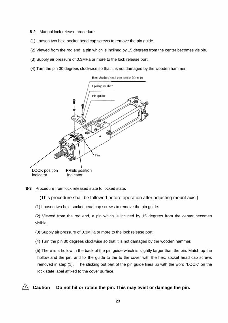
8-2 Manual lock release procedure
(1) Loosen two hex. socket head cap screws to remove the pin guide.
(2) Viewed from the rod end, a pin which is inclined by 15 degrees from the center becomes visible.
(3) Supply air pressure of 0.3MPa or more to the lock release port.
(4) Turn the pin 30 degrees clockwise so that it is not damaged by the wooden hammer.
LOCK 位置表示 FREE 位置表示
8-3 Procedure from lock released state to locked state.
(This procedure shall be followed before operation after adjusting mount axis.)
(1) Loosen two hex. socket head cap screws to remove the pin guide.
(2) Viewed from the rod end, a pin which is inclined by 15 degrees from the center becomes
visible.
(3) Supply air pressure of 0.3MPa or more to the lock release port.
(4) Turn the pin 30 degrees clockwise so that it is not damaged by the wooden hammer.
(5) There is a hollow in the back of the pin guide which is slightly larger than the pin. Match up the
hollow and the pin, and fix the guide to the to the cover with the hex. socket head cap screws
removed in step (1). The sticking out part of the pin guide lines up with the word “LOCK” on the
lock state label affixed to the cover surface.
Caution Do not hit or rotate the pin. This may twist or damage the pin. !
Pin
Pin guide
Spring washer
Hex. Socket head cap screw M4x10
LOCK position FREE position indicator indicator
24
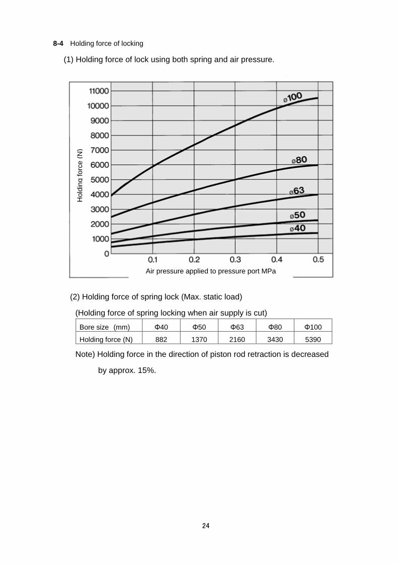
8-4 Holding force of locking
(1) Holding force of lock using both spring and air pressure.
(2) Holding force of spring lock (Max. static load)
(Holding force of spring locking when air supply is cut)
Bore size (mm) Φ40 Φ50 Φ63 Φ80 Φ100
Holding force (N) 882 1370 2160 3430 5390
Note) Holding force in the direction of piston rod retraction is decreased
by approx. 15%.
Hold
ing
fo
rce
(N
)
Air pressure applied to pressure port MPa

25
8-5 Allowable kinetic energy
Please refer to the diagram below.
Allowable Kinetic Energy Diagram