Embed Size (px)
Citation preview

Available online at www.sciencedirect.com
Physics Procedia 00 (2009) 000–000
www.elsevier.com/locate/procedia
International Congress on Ultrasonics, Universidad de Santiago de Chile, January 2009
Monochromatic Transfer Matrix method for acoustic field simulation thorough media boundaries
A. Ibáñeza*, C. Fritscha, M. Parrillaa, J. Villazóna
aInstituto de Automática Industrial (CSIC), La Poveda, Arganda, 28500 Madrid, Spain
Elsevier use only: Received date here; revised date here; accepted date here
Abstract
In ultrasonic NDE applications, situations involving propagation of acoustic waves through interfaces are usual. Effects of reflection, refraction, diffraction, and mode changes at interfaces must be considered both to plan and to explain inspections.Ray-tracing based simulation methods, commonly used, have a limited or null consideration of much of involved physic phenomena. In the other hand, numeric methods for acoustic field simulation are usually computationally expensive and non suitable for interactive applications. In this work we present a full matrix formulated method for continuous wave field simulation in which each process: propagation in homogeneous media, refraction at interfaces, etc., are described by matrices thatcan be composed to model a complex problem with a single Monochromatic Transfer Matrix that can be used to interactively compute fields produced by different excitation patterns of the used transducers.
PACS: 43.20; 43.30; 43.60
Keywords: Acoustic Field Simulation; Interfaces; Monochromatic Transfer Matrix
1. Introduction
The inspection of parts composed of some homogeneous regions separated by soft curved interfaces is a usual situation in ultrasonic NDE. Computer programs that simulate the propagation of acoustic waves through such structures are useful tools for determining suitable positions of transducers, the geometry of wedges needed to make ultrasonic test beams arrive to the regions of interest, and to predict how echoes originated at structural elements of the part being inspected return to the transducers making possible to distinguish them from echoes produced by flaws. In addition, the growing use of phased array systems that requires use a great number of foci to perform a singles scan -specially when dynamic deep focusing is used- and the essentially interactive nature of the inspection design process imposes the use of fast tools to compute and verify the focal laws to be applied, both for emission and reception.
* Corresponding author. Tel.: +3491-871-19-99; fax: +3491-871-70-50. E-mail address: [email protected].
Physics Procedia 3 (2010) 883–890
www.elsevier.com/locate/procedia
doi:10.1016/j.phpro.2010.01.113

A. Ibáñez et al./ Physics Procedia 00 (2010) 000–000
Most of time-domain methods for simulating the propagation of elastic and acoustic waves in materials are usually founded in the numerical solution of the system governing equations. So, Finite Elements Methods [1] orFinite Differences Time Domain Methods [2] are solutions of the differential wave equation; Finite IntegralMethods [3] start from integral forms of the governing equations. Other approaches such as Mass Spring LatticeModels use discrete models of continuous media and solve the movement equations at each particle [4]. All this methods have in common the use of dense grids of points to model the space from wave sources to targets and it is necessary compute fields at every point at shorts time intervals, what supposes a huge computing task an long timesfor computing beams.
Ray-tracing [5] based methods are the most used in NDE due to its capability to determine paths followed byultrasonic beams at interfaces (reflection and refraction), and to measure times of flight over them, which permits,for example, to predict arrival times of echoes or to calculate the focal laws to be applied in inspections performedwith phased array transducers. A drawback of ray based methods is its limited or null capability to reproducediffraction and interference effects, which are essential to verify the application of focal laws.
In this work, we present a matrix formulation of a method for simulating beam patterns of harmonic continuouswaves in homogeneous media with soft curved interfaces. The method is fast enough to be used interactively andcan be a complement to ray tracing methods.
2. The Monochromatic Transfer Matrix (MTM) method
2.1. Theoretical fundaments
The well known solution of the wave equation for a baffled plane source of scalar complex harmonic wavesradiating into a homogeneous infinite half space [6] takes the general form of the integral equation:
dsrErPhPU ,00 (1)
which provides the complex amplitude of the acoustic field at point P0 as a superposition of the excitat )(rEionover all the radiating aperture with an attenuation factor and a change of phase given by the ion ),( 0 rPhfunct ,which is a function of the target point P0 and of the distance r from P0 to each point in the aperture . The form of his dependent of the applied boundary conditions so, for the “soft-baffle” condition, it takes the form:
)cos(exp2
),( 0 rjkrjkrPh (2)
rwhere k is the wave number and is the angle formed by the normal to the aperture and the vector with origin at P0 and its end in the aperture. For the “rigid-baffle” condition h is given as:
rjkrrPh exp
21),( 0
(3)
In general an analytical solution of the integral (1) can’t be obtained, but its numerical solution is the basis of themethod for fast computing beam patterns that is presented in this work. Its main advantages, for this purpose, are that geometry and excitation dependences are fully separated, and that it is only necessary to know the excitation atthe aperture to compute the amplitude and phase of vibration at any point of the space.
884 A. Ibanez et al. / Physics Procedia 3 (2010) 883–890

A. Ibáñez et al./ Physics Procedia 00 (2010) 000–000
3. Description of the simulation method
To numerically solve (1), the aperture can be divided in a set of n cells sj, small enough to considerer that both,h(P0, r)=hj(P0) and the excitation function E(r)=Ej, are constant in every cell. Fig.1 illustrates the geometricalrelations between the involved elements. Substituting the integral in (1) by a sum over all cells results:
(4)jj jjjj j EPmsEPhPU 000
Pi
S
sj
ijr
jnij
Fig.1 Radiating aperture and target point
Now, for a set {Pi} of m target points, it can be defined a field vector U in which each term Ui represents thecomplex amplitude of the acoustic field at the target i, and a excitation vector E with the component Ej being thecomplex amplitude of the excitation applied to the j-cell of the radiating aperture . By applying (4) to the whole setof targets and using matrix notation the relation between U and E is given by:
(5)ETU
where * means the usual matrix multiplication. We call Monochromatic Transfer Matrix (MTM) to the operator T
that computes the field at targets as a superposition of the fields propagated from each source. The elements mij ofthe mxn matrix T are given by:
cosexp
2
exp2
)(ij
ij
ijj
ij
ijj
jijij
rjkrjks
rjkrs
sPhm (6)
depending of the applied boundary conditions. Each term is only function of the sources-target distances and of thewavelength in the medium, and it is independent of the acoustical magnitudes (pressure, density, displacement,velocity potential…) used to represent both the field and the excitation.
Equations (5) and (6) are the basis of an efficient field simulation computer program, which is fast enough tointeractively modify the excitation vector and observe the effects at the targets. The program operates in two stages:
1. Modeling stage: in which, for a given arrangement of sources, interfaces and targets the MTM is computedusing (6). The inter-cells distance must be maintained lower than a half wavelength to avoid creatingfictitious grating lobes.
A. Ibanez et al. / Physics Procedia 3 (2010) 883–890 885

A. Ibáñez et al./ Physics Procedia 00 (2010) 000–000
2. Field computing stage: by evaluating (5) for each specified excitation vector.
Modeling of large apertures, in relation to the wavelength, can result in a big number of source cells within theaperture, which can cause the overflow of the available computer memory. However, due to the matrix form of (6) is possible to divide the aperture, and/or the target points set, in some separate subsets that can be independentlyevaluated (sequentially or in parallel on a multiprocessor computer or in a computing grid). A most effectiveapproach, which can be combined with the former, is to reduce the whole size of the MTM.
4. MTM of piston sources with apodization
Ultrasonic transducers can be considered as radiating elements excited by a single driving signal. A usualapproach is to considerer that the transducer behaves like a piston or, in a most realistic situation, as a pistonmodulated by a -possibly complex- apodization function which reproduces differences, in amplitude and phase, of the excitation along its surface. This way, for a transducer modeled by n radiating surface cells with apodizationcoefficients Aj at each cell, the excitation vector can be written as:
EEAEA jj AE (7)
where the complex scalar E is the common -piston- part of the excitation, and A is the apodization vector of theaperture. Substituting (7) in (5):
(8)EE VATETU
in which the mxn matrix T has been replaced by the m elements column vector V, and the excitation vector E by thescalar E. By applying (7) a transducer, no matter its size, can be represented by a column vector with a number ofrows equal to the number of target points. This is especially useful when modeling phased array transducers, whereeach array element can be modeled as an apodized piston and the amplitude at targets is the sum of amplitudes duesto each element. By applying (7) to an N element phased array transducer this superposition can be written as a matrix equation formally identical to (5):
(9)ETVUU,Nj
jj,Nj
j E11
Now, each column of the resulting MTM T, is the column vector defined in (8) for each array element, and theexcitation vector E is the applied focal law.
5. Modeling propagation at interfaces
The use of solid or liquid wedges for coupling transducers to inspected parts is a common fact in non-destructiveevaluation of components as is to inspect structures with discontinuities. The distortion in the acoustic beamproduced by such interfaces must be evaluated to correctly perform the inspection, and to interpret its results.Integrals solutions, like (1), of the wave equation have been used to model propagation through soft curvedinterfaces [7]. This way, for an acoustic source in a medium 1 separated of an acoustically different medium 2 bythe interface I, as it is shown in Fig. 2, the interface is considered to be a source radiating into medium 2 with an excitation field EI produced by the field radiated from the source . Let be T1I the MTM which computes the field at interface propagated through medium 1, and TI2 the MTM which yields the field at targets in medium 2 given thefield at interface. Using (6) the field vector U at targets is given by:
(10)ET12ET1ITI2ET1ITI2ETI2U I
886 A. Ibanez et al. / Physics Procedia 3 (2010) 883–890

A. Ibáñez et al./ Physics Procedia 00 (2010) 000–000
I
medium 1 medium 2
Fig.2 Field propagated through an interface
which states that the MTM that directly computes the field U at targets in medium 2 from the excitation E of sourcesin medium 1, is the product of the MTM from the interface to the targets by the MTM from the sources to theinterface. Equation (10) naturally gives account of refraction, reflection and mode changes at interfaces if the rightvalue of the wavenumber k is used in T1I and TI2.
In order to accomplish with energy conservation and field continuity at both sides of interfaces, matrices of transmission Tr and reflection Rf can be defined for each vibration mode. The element tij of Tr is the transmissioncoefficient at point i of the interface for the field propagated from the source j, and the same way for reflectionmatrix. For example, to compute the refracted shear wave at targets for an incident longitudinal wave, equation (10)is modified as:
(11)ET1ITrTI2ET1ITrTI2U lsls
where denotes element by element matrix product.
6. Phase conjugation for focal law computing
In general, ray-tracing methods are fast for computing forward sound trajectories starting from sources. Moredifficult is to find the ray that connects a target with a given source [8], which is the problem involved in focal lawscomputing. The MTM method offers a straightforward way of calculating focal laws as phase delays by the use ofphase conjugation which is the frequency domain equivalent to Time of flight reversal [9]. In this approach, thedesired focal points are considered punctual sources from which the field at the transducers surface is computed. By emitting with the phase conjugated of that field (in fact the amplitude is not relevant) a beam which reverses the pathof the former is obtained.
Another possibility is to use the pseudo-inverse matrix method [10] to solve the matrix equation (6).
7. Simulation examples
7.1. Verification of ray tracing computed focal laws.
As an example of the capabilities of the described method, we have performed the simulation of the beam-patterns for each focal law computed by means of ray tracing, as described in [8], for the inspection of a 90º, 100mmof radius sector made of aluminum. The inspection is to be performed with a 5 MHz and 96 elements phased array. Each element is a rectangle of 0.4mm x 10mm. Inter element pitch is 0.5 mm. The scanned sector is composed of
A. Ibanez et al. / Physics Procedia 3 (2010) 883–890 887
A. Ibáñez et al./ Physics Procedia 00 (2010) 000–000
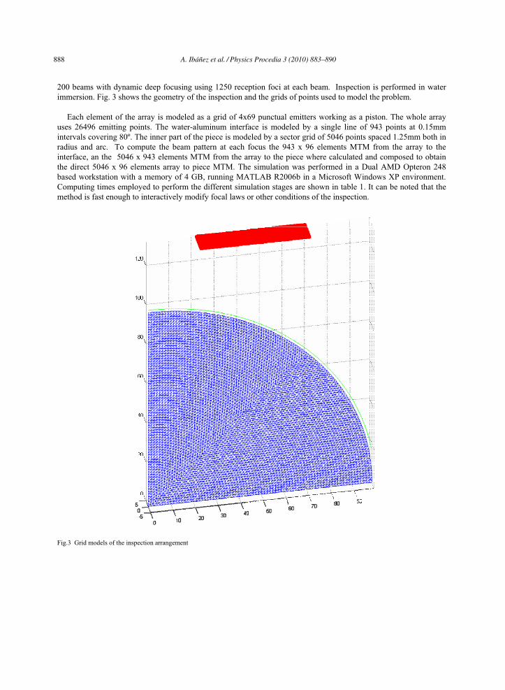
200 beams with dynamic deep focusing using 1250 reception foci at each beam. Inspection is performed in waterimmersion. Fig. 3 shows the geometry of the inspection and the grids of points used to model the problem.
Each element of the array is modeled as a grid of 4x69 punctual emitters working as a piston. The whole arrayuses 26496 emitting points. The water-aluminum interface is modeled by a single line of 943 points at 0.15mm intervals covering 80º. The inner part of the piece is modeled by a sector grid of 5046 points spaced 1.25mm both in radius and arc. To compute the beam pattern at each focus the 943 x 96 elements MTM from the array to theinterface, an the 5046 x 943 elements MTM from the array to the piece where calculated and composed to obtainthe direct 5046 x 96 elements array to piece MTM. The simulation was performed in a Dual AMD Opteron 248based workstation with a memory of 4 GB, running MATLAB R2006b in a Microsoft Windows XP environment.Computing times employed to perform the different simulation stages are shown in table 1. It can be noted that themethod is fast enough to interactively modify focal laws or other conditions of the inspection.
Fig.3 Grid models of the inspection arrangement
888 A. Ibanez et al. / Physics Procedia 3 (2010) 883–890

A. Ibáñez et al./ Physics Procedia 00 (2010) 000–000
Table 1. Simulation computing times.
Array- Interface MTM 2.4 s
Interface-Piece MTM 0.54 s
Array-Piece MTM 1.8 s
Beam-pattern rate (without drawing) 55 frames/s
Beam-pattern rate (drawing) 6 frames/s
Fig. 4 shows the concordance at to different focus between the models of rays used to compute the focal laws andthe beam patterns obtained by the MTM method.
(b)
(a)
Fig.4 Field Simulation at two foci. (a) Model of rays used to obtain the focal laws. (b) Beam pattern computed with the MTM method usingthese focal laws.
8. Conclusion
The proposed MTM method for computing beam-patterns can response the precision and speed needs of phasedarray NDE interactive inspections preparing. The method yields amplitude and phase information at each computed
A. Ibanez et al. / Physics Procedia 3 (2010) 883–890 889

A. Ibáñez et al./ Physics Procedia 00 (2010) 000–000
point, and makes possible to model reflection, refraction and mode changes at interfaces. In addition it gives account of diffraction and interference effects.
Aknowledgements
Work supported by the Project TRA-2007-67711/AVT of the Spanish Ministry for Science and Innovation.
References
[1] J. Mackerle, "Finite-element modelling of non-destructive material evaluation: a bibliography (1976-1997)," Modelling Simul. Mater. Sci. Eng. 7, pp. 107-145, 1999.
[2] I. M. Hallaj and R. O. Cleveland, "FDTD simulation of finite-amplitude, pressure and temperature fields for biomedical ultrasound," J.Acoust. Soc. Am. vol. 105(5), pp. L7-L12, 1999.
[3] R. Marklein, "NDT Related Quantitative Modeling of Coupled Piezoelectric and Ultrasonic Wave Phenomena," ECNDT 1998 Conference,Copenhagen, Denmark, May 26-29, 1998.
[4] K. Harumi, "Computer simulation of ultrasonics in a solid," NDTInt , vol. 19, no. 5, pp. 315–332, 1986. [5] G. A. Deschamps, "Ray techniques in electromagnetics," Proc. IEEE, vol. 60, pp. 1022-1035, 1972. [6] J. W. Goodman, "Introduction to Fourier Optics," Physical and Quantum Electronics series, Mc Graw-Hill, New York, 1968. [7] P. Calmon and O. Roy, "Simulation of UT examinations: Modeling of the beam-defect interaction," Review of Progress in QNDE, vol. 13,
pp. 101–108, D. O. Thompson and D. E. Chimenti, Eds. New York Plenum, 1994. [8] M. Parrilla, J. Brizuela, J. Camacho, A. Ibañez, P. Nevado, C. Fritsch, "Dynamic focusing through arbitrary geometry interfaces," IEEE
International Ultrasonics Symposium - Beijing, November 2-5, 2008. [9] M. Fink, "Time Reversal of Ultrasonic Fields. – Part I: Basic Principles," IEEE Transactions on Ultrasonics, Ferroelectrics, and Frequency
Control, vol. 39, no. 5, pp. 555-566, 1992. [10] E. S. Ebbini and C. A. Cain, "Multiple-Focus Ultrasound Phased-Array Pattern Synthesis: Optimal Driving-Signal Distributions for
Hyperthermia," IEEE Transactions on Ultrasonics, Ferroelectrics, and Frequency Control, vol. 36, no. 5, pp. 540-548, 1989.
890 A. Ibanez et al. / Physics Procedia 3 (2010) 883–890