Embed Size (px)
Citation preview

- 1 -
Information to Users
This equipment has been tested and found to comply with the limits for a Class B digital devices, pursuant to Part 15 of the FCC Rules. These limits are designed to provide reasonable protection against harmful interference in a residential installation. This equipment generates, uses, and can radiate radio frequency energy and, if not installed and used in accordance with the instruction manual, may cause harmful interference to radio communications. However, there is no guarantee that interference will not occur in a particular installation. If this equipment does cause harmful interference to radio or television reception, which can be determined by turning the equipment off and on, the user is encouraged to try to correct the interference by one of more of the following measures:
• Reorient or relocate the receiving antenna
• Increase the separation between the equipment and receiver
• Connect the equipment into an outlet on a circuit different from that to which the receiver is connected.
• Consult the dealer or an experienced radio/TV technician for help.
WARNING: Changes or modifications not expressly approved by Monnit could void the user’s
authority to operate the equipment.
RF EXPOSURE WARNING: To satisfy FCC RF exposure requirements for mobile transmitting
devices, a separation distance of 20 cm or more should be maintained between the antenna of this device and persons during device operation. To ensure compliance, operations at closer than this distance are not recommended. The antenna used for this transmitter must not be co-located in conjunction with any other antenna or transmitter.
Inside the Box
You should find the following items in the box: • Monnit Serial MODBUS Gateway • Antenna • Monnit Wireless Sensors • Batteries • Mounting Hardware • Users Guide
Some setup is required before the system will begin working. Please follow the instructions in this guide to correctly setup your system.
Monnit Wireless Sensors
Serial MODBUS
(RTU/ASCII) Gateway
Quick Start Guide For Version 3.1

- 2 -
Features
Works with Monnit 900, 868 and 433MHz Sensor
Networking Solutions
Communicates with MODBUS RTU / ASCII Protocols
Supports RS-232C / RS-485 Interfacing
3 LED Indicators (System, Wired and Wireless)
NEMA 4X / IP65 Rated Enclosure
RP SMA Antenna Connector (Antenna Included)
Example Network Integration
Monnit wireless sensors integrate with existing MODBUS systems allowing for additional environmental variables to be monitored.
Monnit Serial MODBUS Gateway Quick Start
1. Attach Hardware 2. Verify COM Settings 3. Perform Communication Verification 4. Register Sensors to SMG 5. Bring Sensors Online 6. Read / Interpret Sensor Data

- 3 -
1. Connecting The Serial MODBUS Gateway Hardware
1. Connect Antenna
2. Use communication select jumper to set RS-485 or RS-232C
3. Connect wires from MODBUS to SCADA / PLC / Master
SMG 5-Wire Connector
Red: 4.5 – 36 VDC
Black: Power ground
Orange: RS-232C: TXD gateway’s transmitter data connection. Connect the MODBUS master’s receiver. RS-485: D+ Non-inverting 485 transmitter/receiver.
White: Signal ground, internally connected to power ground.
Green: RS-232C: RXD gateway’s receiver data connection. Connect the MODBUS master’s transmitter. RS-485: D- Inverting 485 transmitter/receiver.

- 4 -
Connecting the Serial MODBUS Gateway to the USB Programming Dongle:
2. Serial MODBUS Gateway Indicator Lights
System - Indicates gateway status. A green light indicates ready and working, a red light indicates there is a hardware problem. Wired - Indicates connectivity with MODBUS system. A green light indicates ready and working, a red light indicates there is a problem. A flashing green light indicates active communication.
Wireless - Indicates wireless sensor network activity. A green light indicates ready and working, a red light indicates that no network has been formed (no sensors are registered). A flashing green light indicates radio traffic from the sensors.
- 5 -
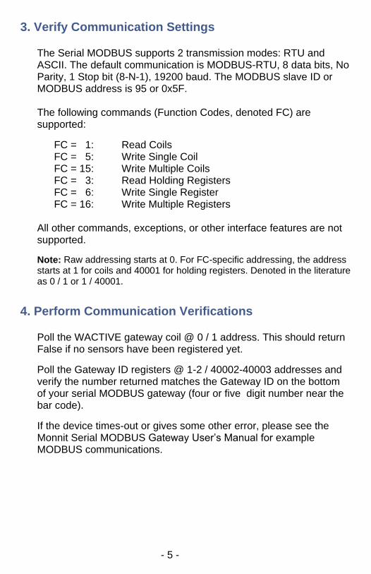
3. Verify Communication Settings
The Serial MODBUS supports 2 transmission modes: RTU and ASCII. The default communication is MODBUS-RTU, 8 data bits, No Parity, 1 Stop bit (8-N-1), 19200 baud. The MODBUS slave ID or MODBUS address is 95 or 0x5F. The following commands (Function Codes, denoted FC) are supported:
FC = 1: Read Coils FC = 5: Write Single Coil FC = 15: Write Multiple Coils FC = 3: Read Holding Registers FC = 6: Write Single Register FC = 16: Write Multiple Registers
All other commands, exceptions, or other interface features are not supported.
Note: Raw addressing starts at 0. For FC-specific addressing, the address starts at 1 for coils and 40001 for holding registers. Denoted in the literature as 0 / 1 or 1 / 40001.
4. Perform Communication Verifications
Poll the WACTIVE gateway coil @ 0 / 1 address. This should return False if no sensors have been registered yet.
Poll the Gateway ID registers @ 1-2 / 40002-40003 addresses and verify the number returned matches the Gateway ID on the bottom of your serial MODBUS gateway (four or five digit number near the bar code).
If the device times-out or gives some other error, please see the Monnit Serial MODBUS Gateway User’s Manual for example MODBUS communications.

- 6 -
Change Communication Settings
If you prefer to use different communication settings than the default, follow the instructions on the next page. Otherwise, skip to the next section.
Register Name
Function Code
Raw Address
Description
BAUDRATE 40006 5 Designates the baud rate used by the MODBUS interface. After modifying this register, a gateway reset must be performed before changes can take effect. Value Represented Baud Selected
0 2400 1 4800 2 9600 3 (DEFAULT) 19200 4 38400 5 57600 6 115200
COMMODE 40007 6 Designates the operating mode used by the MODBUS interface. After modifying this register, a gateway reset must be performed before changes can take effect. Value Meaning 0 RTU : 8-N-2 1 (DEFAULT) RTU : 8-N-1 2 RTU : 8-E-1 3 RTU : 8-0-1 4 ASCII : 7-N-2 5 ASCII : 7-E-1 6 ASCII : 7-O-1
COMADDR 40008 7 Designates the MODBUS Address used in the communications interface. Values range from 1-247. Default value is 95.
Once you have written your new settings, you will have to perform a reset for the settings to take effect.
- 7 -
To perform a reset, write the “RST_DEVICE” Gateway Coil @ address 3 to TRUE. The device will reset one second after receiving this command. Your new communication settings will be in effect. You can also power cycle the gateway and get the same result.
To verify them, attempt to read the Gateway ID from registers 40002 - 40003.
5. Adding a Wireless Device to the Gateway
DO NOT INSERT BATTERIES UNTIL SENSOR HAS BEEN REGISTERED.
In order for the Serial MODBUS Gateway to activate the wireless network, you will need to register at least one wireless device.
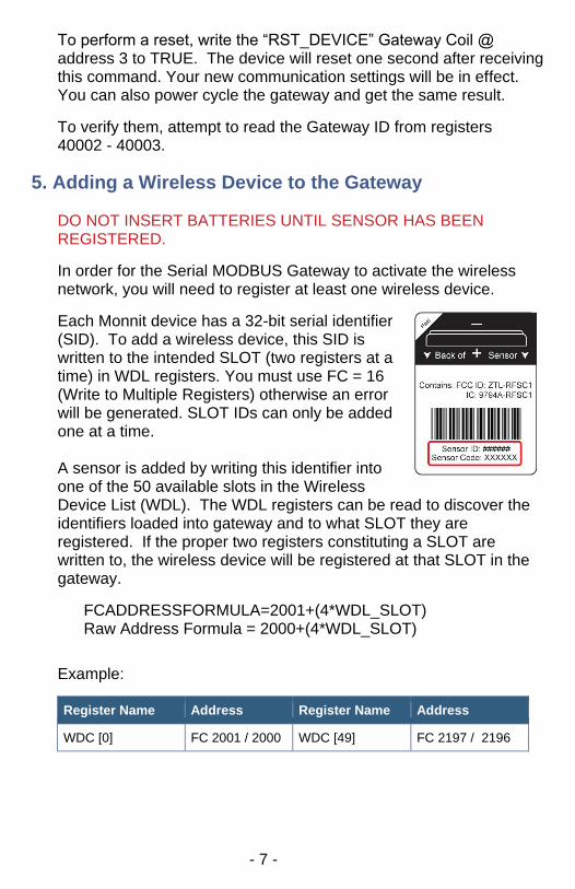
Each Monnit device has a 32-bit serial identifier (SID). To add a wireless device, this SID is written to the intended SLOT (two registers at a time) in WDL registers. You must use FC = 16 (Write to Multiple Registers) otherwise an error will be generated. SLOT IDs can only be added one at a time. A sensor is added by writing this identifier into one of the 50 available slots in the Wireless Device List (WDL). The WDL registers can be read to discover the identifiers loaded into gateway and to what SLOT they are registered. If the proper two registers constituting a SLOT are written to, the wireless device will be registered at that SLOT in the gateway.
FCADDRESSFORMULA=2001+(4*WDL_SLOT) Raw Address Formula = 2000+(4*WDL_SLOT)
Example:
Register Name Address Register Name Address
WDC [0] FC 2001 / 2000 WDC [49] FC 2197 / 2196

- 8 -
When registering your first device, the gateway will need time to form its first network, which takes 30 seconds. During this time, the middle LED will go red signifying there is no wired communication available, then the third LED will start flashing while the wireless network forms. After the first device registration is complete, any subsequent registrations can be one right after the other, as the network only needs to form once.
You can verify that the network is active by polling the WACTIVE coil @ 0 / 1 address. If it now returns true, the registration of the first wireless device is successful, and the wireless network is now active.
Add more wireless devices using the same method, but you will not need to wait 30 seconds after each. To see the current wireless device count, read register @ 3 / 40004 address.
Register Name Function Code
Raw Address
Description
WD_CNT 40004 3 Wireless Device Count – Value that can be read to discover the number of registered sensors are configured to operate on the gateway. A value 0 – 50 is permitted. (READ-ONLY) Example Value: 0 (no sensors registered, factory reset condition) Example Value: 10 (10 Registered device)
6. Bring Sensors Online
To bring your sensors online, insert the battery into the sensors. Once the battery is inserted, the wireless device does a scan to look for the network. As long as the gateway is ACTIVE, the sensor will link up to the network.
- 9 -
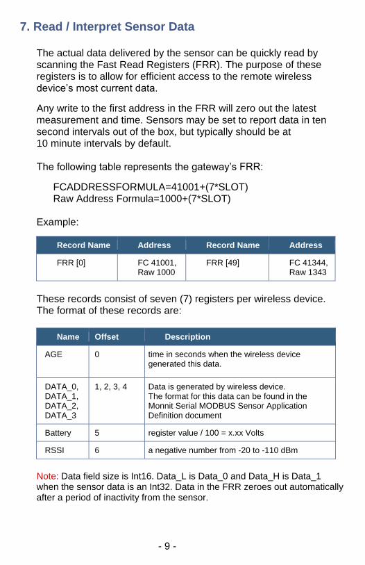
7. Read / Interpret Sensor Data
The actual data delivered by the sensor can be quickly read by scanning the Fast Read Registers (FRR). The purpose of these registers is to allow for efficient access to the remote wireless device’s most current data.
Any write to the first address in the FRR will zero out the latest measurement and time. Sensors may be set to report data in ten second intervals out of the box, but typically should be at 10 minute intervals by default. The following table represents the gateway’s FRR:
FCADDRESSFORMULA=41001+(7*SLOT) Raw Address Formula=1000+(7*SLOT)
Example:
Record Name Address Record Name Address
FRR [0] FC 41001, Raw 1000
FRR [49] FC 41344, Raw 1343
These records consist of seven (7) registers per wireless device. The format of these records are:
Name Offset Description
AGE 0 time in seconds when the wireless device generated this data.
DATA_0, DATA_1, DATA_2, DATA_3
1, 2, 3, 4 Data is generated by wireless device. The format for this data can be found in the Monnit Serial MODBUS Sensor Application Definition document
Battery 5 register value / 100 = x.xx Volts
RSSI 6 a negative number from -20 to -110 dBm
Note: Data field size is Int16. Data_L is Data_0 and Data_H is Data_1 when the sensor data is an Int32. Data in the FRR zeroes out automatically after a period of inactivity from the sensor.
- 10 -
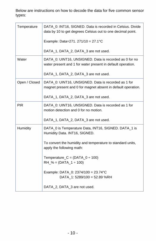
Below are instructions on how to decode the data for five common sensor types:
Temperature DATA_0: INT16, SIGNED. Data is recorded in Celsius. Divide
data by 10 to get degrees Celsius out to one decimal point.
Example: Data=271. 271/10 = 27.1°C
DATA_1, DATA_2, DATA_3 are not used.
Water DATA_0: UINT16, UNSIGNED. Data is recorded as 0 for no
water present and 1 for water present in default operation.
DATA_1, DATA_2, DATA_3 are not used.
Open / Closed DATA_0: UINT16, UNSIGNED. Data is recorded as 1 for
magnet present and 0 for magnet absent in default operation.
DATA_1, DATA_2, DATA_3 are not used.
PIR DATA_0: UINT16, UNSIGNED. Data is recorded as 1 for
motion detection and 0 for no motion.
DATA_1, DATA_2, DATA_3 are not used.
Humidity DATA_0 is Temperature Data, INT16, SIGNED. DATA_1 is
Humidity Data. INT16, SIGNED.
To convert the humidity and temperature to standard units,
apply the following math:
Temperature_C = (DATA_0 ÷ 100)
RH_% = (DATA_1 ÷ 100)
Example: DATA_0: 2374/100 = 23.74°C
DATA_1: 5289/100 = 52.89 %RH
DATA_2, DATA_3 are not used.

- 11 -
Troubleshooting If you cannot talk to the Serial MODBUS Gateway, please double check the following: Verify the voltage on the red wire interfaced to our unit is 4.5V – 36.0 VDC. When powering the device you should see the startup indicator lights flash red and green for ~4 seconds. Verify the top and middle lights are green and the middle light flashes when communicating with the MODBUS master. If the middle light is not green, please refer to Section 2 Serial MODBUS Gateway – Indicator Lights. Verify your communication select jumper matches what you are using, whether it is RS-485 or RS-232C. Verify the data lines, matching the colors of our wires to their respective lines. See the image on page 3 to verify. Verify your baud rate and operating mode. If you have made changes to the baud rate, operating mode, or other and have lost communication, perform a factory reset, by opening up the Serial MODBUS gateway and finding the COM reset and jumper. To do a factory reset, apply the jumper. Power on the gateway. Deliberately remove and replace the jumper twice. All indicator lights will flash red quickly (5x / sec) when the device has been successfully reset. Unpower the gateway and remove the jumper. After powering the gateway again, it will now operate with the factory default settings. If there is an internal memory failure, all indicator lights will stay red after startup. If this occurs, contact Monnit customer support at [email protected]. For additional technical support and troubleshooting tips please visit our support library online at http://www.monnit.com/support/. If you are unable to solve your issue using our online support, email Monnit support at [email protected] with your contact information and a description of the problem, and a support representative will respond within one business day. For error reporting, please email a full description of the error to [email protected].

- 12 -
For additional information or more detailed instructions on how to use your Monnit Serial MODBUS Gateway or Monnit Wireless Sensors, please view our support information and documentation on the web at http://www.monnit.com/support/.
View the full user’s guide at http://www.monnit.com/smg-guide.
Monnit Corporation 4300 South West Temple South Salt Lake, UT 84115 801-561-5555 www.monnit.com
Monnit, Monnit Logo and all other trademarks are property of Monnit, Corp. © 2009-2016 Monnit Corp. All Rights Reserved. MQS06-3D (12/16)