Embed Size (px)
Citation preview

MonnitLink™ Ethernet Gateway Quick Start • Create a Monnit user account with assigned wireless gateways and sensors. • Attach the antenna to the antenna connector on the back panel of the Ethernet gateway (make sure the connection is snug, but do not overtighten). • Plug an Ethernet cable with internet connectivity into the gateway. • Plug the power supply into a power outlet then connect to the gateway. • Once all three lights turn green, your network is ready to bring sensors online.
Monnit Wireless Sensors and Ethernet Gateway
User’s Guide
For Use With iMonnit Online Softwareand iMonnit Express PC Software
1. Create a Monnit User Account and Setup Sensor Network
If this is your first time using the iMonnit online system site, you will need to create a new account. If you have already created an account you can skip to the “Logging into the Online System” section. The following instructions will guide you through the account creation process.
1. In a web browser, navigate to https://www.imonnit.com.
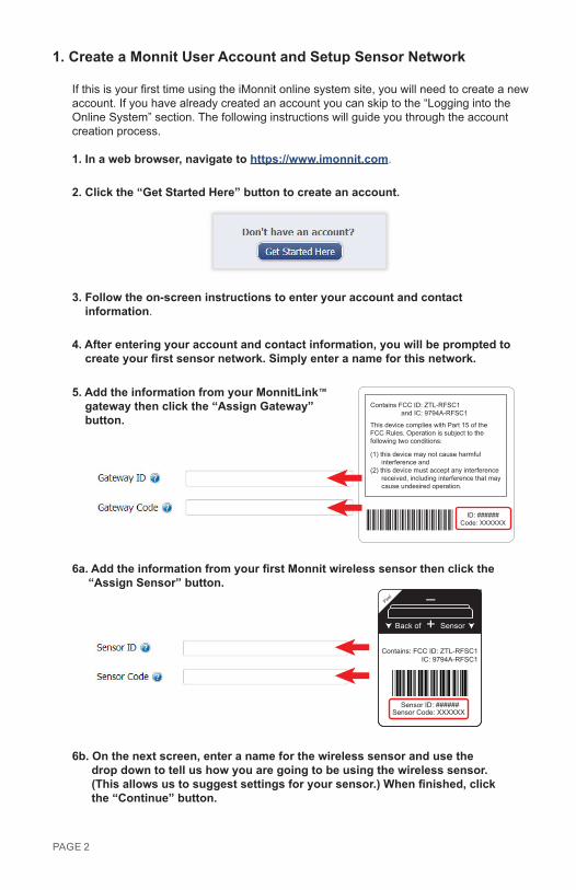
2. Click the “Get Started Here” button to create an account.
3. Follow the on-screen instructions to enter your account and contact information.
4. After entering your account and contact information, you will be prompted to create your first sensor network. Simply enter a name for this network.
5. Add the information from your MonnitLink™ gateway then click the “Assign Gateway” button.
6a. Add the information from your first Monnit wireless sensor then click the “Assign Sensor” button.
+_
Back of Sensor
Peel
Contains: FCC ID: ZTL-RFSC1IC: 9794A-RFSC1
Sensor ID: ######Sensor Code: XXXXXX
6b. On the next screen, enter a name for the wireless sensor and use the drop down to tell us how you are going to be using the wireless sensor. (This allows us to suggest settings for your sensor.) When finished, click the “Continue” button.
PAGE 2
Contains FCC ID: ZTL-RFSC1 and IC: 9794A-RFSC1
This device complies with Part 15 of the FCC Rules. Operation is subject to the following two conditions:
(1) this device may not cause harmful interference and (2) this device must accept any interference received, including interference that may cause undesired operation.
ID: ######Code: XXXXXX
PAGE 3
7. Confirmation Screen.When you have finished adding the sensor, you will see a confirmation screen. At this point you can assign notifications to the sensor (see Using The iMonnit™ Online Wire-less Sensor System) , assign additional sensors to your account or click “Done” to go to your sensors overview page.
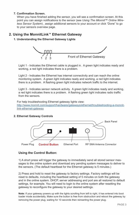
2. Using the MonnitLink™ Ethernet Gateway1. Understanding the Ethernet Gateway Lights
Front of Ethernet Gateway1 2 3
Light 1 - Indicates the Ethernet cable is plugged in. A green light indicates ready and working, a red light indicates there is a problem.
Light 2 - Indicates the Ethernet has internet connectivity and can reach the online monitoring system. A green light indicates ready and working, a red light indicates there is a problem. A flashing green light indicates network traffic to the internet.
Light 3 - Indicates sensor network activity. A green light indicates ready and working, a red light indicates there is a problem. A flashing green light indicates radio traffic from the sensors.
For help troubleshooting Ethernet gateway lights view:http://www.monnit.com/support/hardware/gateways/ethernet/troubleshooting-a-monnit-link-ethernet-gateway
2. Ethernet Gateway Controls
RP SMA Antenna ConnectorEthernet PortPower Plug Control Button
Back Panel
Using the Control Button:
1) A short press will trigger the gateway to immediately send all stored sensor mes-sages to the online system and download any pending system messages to deliver to the sensors. (The default heartbeat for the Ethernet gateway is 5 minutes.)
2) Press and hold to reset the gateway to factory settings. Factory settings will be reset to defaults, including the heartbeat setting of 5 minutes on both the gateway and in the online system. DHCP, server addressing and port are all restored to default settings, for example. You will need to login to the online system after resetting the gateway to reconfigure the gateway to your desired settings.
Note: If your gateway powers up with the lights scrolling from left to right, it has entered into boot loader mode accidentally. Make sure the button is free from obstruction and reboot the gateway by removing the power plug, waiting for 10 seconds then reinserting the power plug.
3. Configuring The Ethernet Gateway The Ethernet Gateway collects data from all sensors within range and is preconfigured to batch deliver the sensor messages to the online system every 5 minutes.
The Ethernet Gateway uses DHCP (Dynamic Host Configuration Protocol) to automatically acquire a network address from the LAN (Local Area Network). In the event that it needs to have an address manually assigned to it, you can assign an IP address as well as a gateway mask and default DNS through the online interface. For more information on configuring the Monnit Ethernet Gateway please view the support documentation at http://www.monnit.com/pdf/Ethernet_Gateway_Configuration.pdf. Note: This advanced configuration is NOT required in most instances. In the event that it is required, you can initialize the gateway on a network that uses the default DHCP settings, or you can follow the instructions for changing the configuration settings on a PC, which are included later in this User’s Guide.
Upon logging into the online system as an administrator, select “My Account” then choose the edit icon next to your sensor network. From there you can alter the heart-beat of the Ethernet Gateway as well as edit any other configurations available. There is also a quick link to reset all gateway settings to factory defaults.
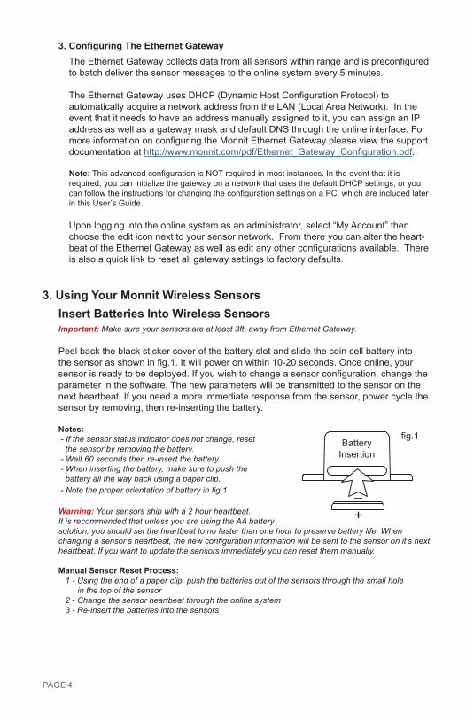
3. Using Your Monnit Wireless SensorsInsert Batteries Into Wireless SensorsImportant: Make sure your sensors are at least 3ft. away from Ethernet Gateway.
Peel back the black sticker cover of the battery slot and slide the coin cell battery into the sensor as shown in fig.1. It will power on within 10-20 seconds. Once online, your sensor is ready to be deployed. If you wish to change a sensor configuration, change the parameter in the software. The new parameters will be transmitted to the sensor on the next heartbeat. If you need a more immediate response from the sensor, power cycle the sensor by removing, then re-inserting the battery.
Notes: - If the sensor status indicator does not change, reset the sensor by removing the battery. - Wait 60 seconds then re-insert the battery. - When inserting the battery, make sure to push the battery all the way back using a paper clip. - Note the proper orientation of battery in fig.1
Warning: Your sensors ship with a 2 hour heartbeat. It is recommended that unless you are using the AA battery solution, you should set the heartbeat to no faster than one hour to preserve battery life. When changing a sensor’s heartbeat, the new configuration information will be sent to the sensor on it’s next heartbeat. If you want to update the sensors immediately you can reset them manually.
Manual Sensor Reset Process: 1 - Using the end of a paper clip, push the batteries out of the sensors through the small hole in the top of the sensor 2 - Change the sensor heartbeat through the online system 3 - Re-insert the batteries into the sensors
PAGE 4
+_
BatteryInsertion
fig.1
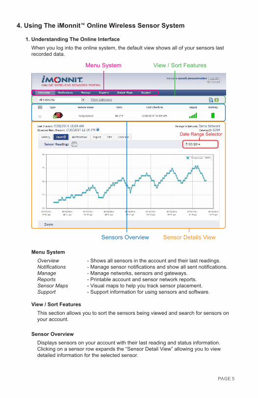
4. Using The iMonnit™ Online Wireless Sensor System
1. Understanding The Online InterfaceWhen you log into the online system, the default view shows all of your sensors last recorded data.
View / Sort FeaturesMenu System
Sensor Details ViewSensors Overview
Date Range Selector
Menu SystemOverview - Shows all sensors in the account and their last readings.Notifications - Manage sensor notifications and show all sent notifications.Manage - Manage networks, sensors and gateways.Reports - Printable account and sensor network reports.Sensor Maps - Visual maps to help you track sensor placement.Support - Support information for using sensors and software.
View / Sort FeaturesThis section allows you to sort the sensors being viewed and search for sensors on your account.
Sensor OverviewDisplays sensors on your account with their last reading and status information. Clicking on a sensor row expands the “Sensor Detail View” allowing you to view detailed information for the selected sensor.
PAGE 5
PAGE 6
To the left side of each sensor row is an indicator to help you understand the current status of the sensor.
Sensor is checking in and within user defined safe parameters.Sensor has met or exceeded a user defined threshold or triggered event.Sensor has not checked in (inactivity alert sent).No sensor readings will be recorded (Inactive)
Sensor Details ViewClicking on a sensor row on the “Overview” page expands the row to include a de-tailed sensor view for the selected sensor.
Select a tab to change between:
History - Displays a history of the selected sensor’s data. Chart - Displays a graphical view of the selected sensor’s data. Notifications - Allows you to manage notifications for the sensor. Export - Allows you to archive data by exporting as a .csv file.Edit - Allows you to manage sensor settings.Calibrate - Available on certain sensor types to provide more accurate data.
Note: The data shown on the chart, notification, history and export tabs is based on the date range indicated on the upper right side of the sensor detail information. To change the date range, click inside the date box.
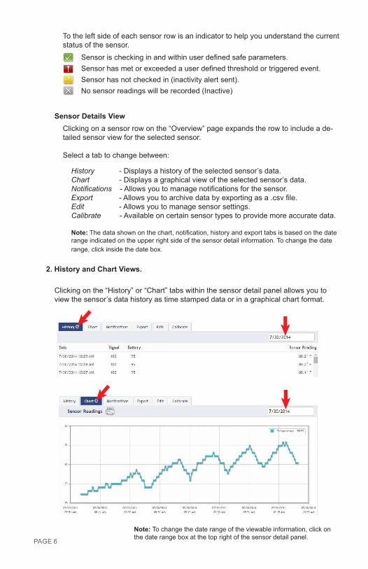
2. History and Chart Views.
Clicking on the “History” or “Chart” tabs within the sensor detail panel allows you to view the sensor’s data history as time stamped data or in a graphical chart format.
Note: To change the date range of the viewable information, click on the date range box at the top right of the sensor detail panel.
PAGE 7
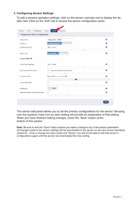
3. Configuring Sensor SettingsTo edit a sensors operation settings, click on the sensor overview row to display the de-tails view. Click on the “Edit” tab to access the sensor configuration panel.
The sensor edit panel allows you to set the primary configurations for the sensor. Mousing over the question mark icon by each setting will provide an explanation of that setting. When you have finished making changes, press the “Save” button at the bottom of this section.
Note: Be sure to click the “Save” button anytime you make a change to any of the sensor parameters.All changes made to the sensor settings will be downloaded to the sensor on the next sensor heartbeat (check-in). Once a change has been made and “Saved,” you will not be able to edit that sensor’s configurations again until the sensor has downloaded the new setting.
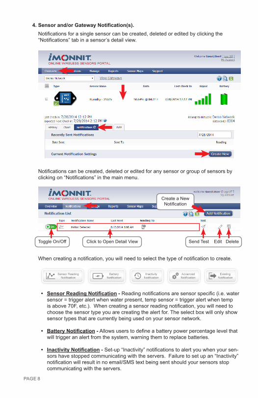
4. Sensor and/or Gateway Notification(s).Notifications for a single sensor can be created, deleted or edited by clicking the “Notifications” tab in a sensor’s detail view.
Notifications can be created, deleted or edited for any sensor or group of sensors by clicking on “Notifications” in the main menu.
Toggle On/Off Click to Open Detail View Send Test Edit Delete
When creating a notification, you will need to select the type of notification to create.
• Sensor Reading Notification - Reading notifications are sensor specific (i.e. water sensor = trigger alert when water present, temp sensor = trigger alert when temp is above 70F, etc.). When creating a sensor reading notification, you will need to choose the sensor type you are creating the alert for. The select box will only show sensor types that are currently being used on your sensor network.
• Battery Notification - Allows users to define a battery power percentage level that will trigger an alert from the system, warning them to replace batteries.
• Inactivity Notification - Set-up “Inactivity” notifications to alert you when your sen-sors have stopped communicating with the servers. Failure to set up an “Inactivity” notification will result in no email/SMS text being sent should your sensors stop communicating with the servers.
PAGE 8
Create a New Notification
• Advanced Notifications - Allows the user to set notifications based on advanced rules, such as comparing past data points with the current one to determine if a notification should be sent.
• Existing Notifications - Use notifications that have already been created on your account with the selected sensor.
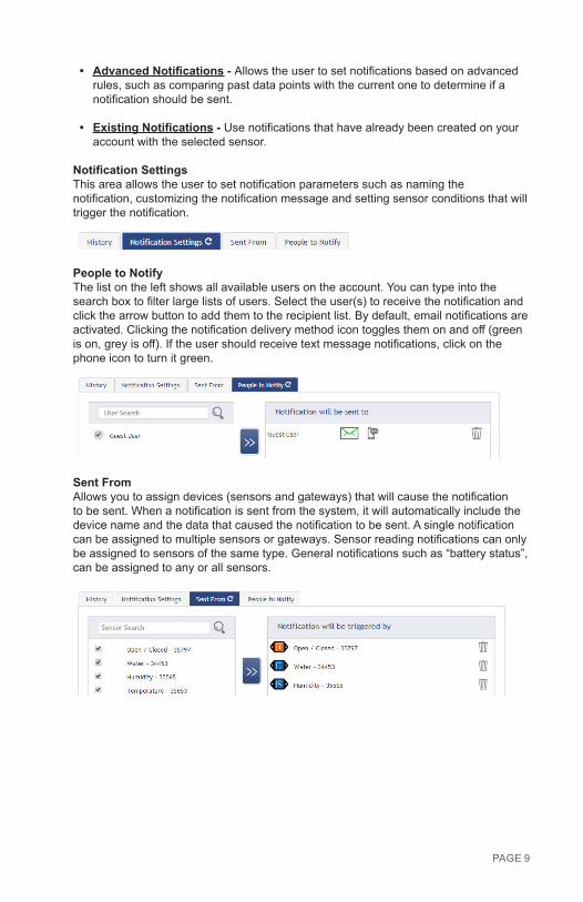
Notification SettingsThis area allows the user to set notification parameters such as naming the notification, customizing the notification message and setting sensor conditions that will trigger the notification.
People to NotifyThe list on the left shows all available users on the account. You can type into the search box to filter large lists of users. Select the user(s) to receive the notification and click the arrow button to add them to the recipient list. By default, email notifications are activated. Clicking the notification delivery method icon toggles them on and off (green is on, grey is off). If the user should receive text message notifications, click on the phone icon to turn it green.
Sent FromAllows you to assign devices (sensors and gateways) that will cause the notification to be sent. When a notification is sent from the system, it will automatically include the device name and the data that caused the notification to be sent. A single notification can be assigned to multiple sensors or gateways. Sensor reading notifications can only be assigned to sensors of the same type. General notifications such as “battery status”, can be assigned to any or all sensors.
PAGE 9
PAGE 10
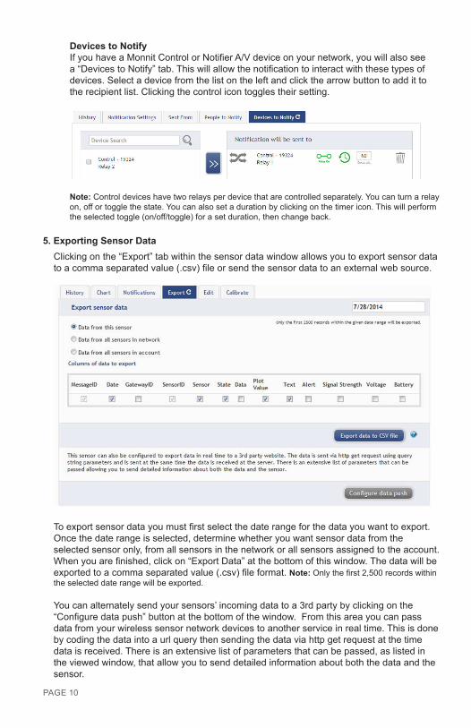
Devices to NotifyIf you have a Monnit Control or Notifier A/V device on your network, you will also see a “Devices to Notify” tab. This will allow the notification to interact with these types of devices. Select a device from the list on the left and click the arrow button to add it to the recipient list. Clicking the control icon toggles their setting.
Note: Control devices have two relays per device that are controlled separately. You can turn a relay on, off or toggle the state. You can also set a duration by clicking on the timer icon. This will perform the selected toggle (on/off/toggle) for a set duration, then change back.
5. Exporting Sensor DataClicking on the “Export” tab within the sensor data window allows you to export sensor data to a comma separated value (.csv) file or send the sensor data to an external web source.
To export sensor data you must first select the date range for the data you want to export. Once the date range is selected, determine whether you want sensor data from the selected sensor only, from all sensors in the network or all sensors assigned to the account. When you are finished, click on “Export Data” at the bottom of this window. The data will be exported to a comma separated value (.csv) file format. Note: Only the first 2,500 records within the selected date range will be exported.
You can alternately send your sensors’ incoming data to a 3rd party by clicking on the “Configure data push” button at the bottom of the window. From this area you can pass data from your wireless sensor network devices to another service in real time. This is done by coding the data into a url query then sending the data via http get request at the time data is received. There is an extensive list of parameters that can be passed, as listed in the viewed window, that allow you to send detailed information about both the data and the sensor.
6. Calibrating Sensor DataCertain wireless sensors can be calibrated for more accurate readings (ex. temperature sensors). If calibration is possible for a sensor, the “Calibrate” tab will be visible in the detail view. To calibrate a sensor, replace the last reading with the more accurate reading and click “Calibrate”. All future readings from the sensor will be based off the new calibration setting.
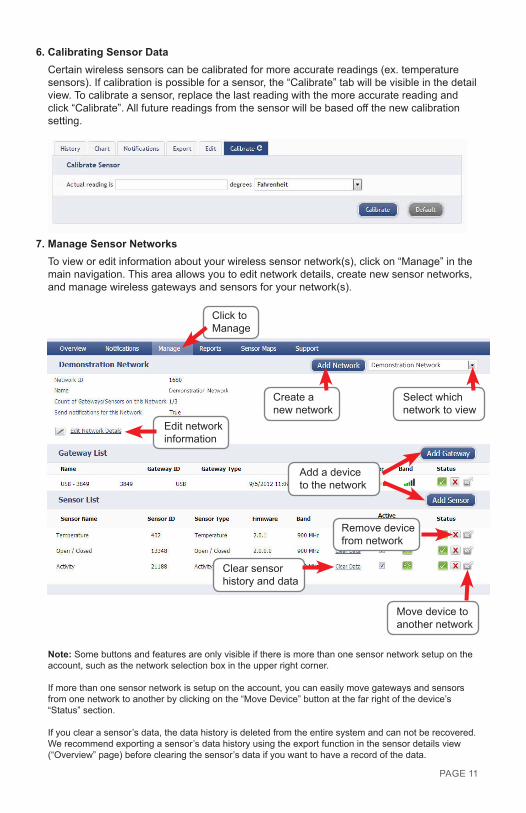
7. Manage Sensor NetworksTo view or edit information about your wireless sensor network(s), click on “Manage” in the main navigation. This area allows you to edit network details, create new sensor networks, and manage wireless gateways and sensors for your network(s).
PAGE 11Move device to another network
Add a device to the network
Create a new network
Remove devicefrom network
Edit networkinformation
Clear sensorhistory and data
Click to Manage
Select which network to view
Note: Some buttons and features are only visible if there is more than one sensor network setup on the account, such as the network selection box in the upper right corner.
If more than one sensor network is setup on the account, you can easily move gateways and sensors from one network to another by clicking on the “Move Device” button at the far right of the device’s “Status” section.
If you clear a sensor’s data, the data history is deleted from the entire system and can not be recovered. We recommend exporting a sensor’s data history using the export function in the sensor details view (“Overview” page) before clearing the sensor’s data if you want to have a record of the data.
PAGE 11
PAGE 12
5. Advanced Settings and Interfacing with the Monnit Ethernet Gateway Through iMonnit.
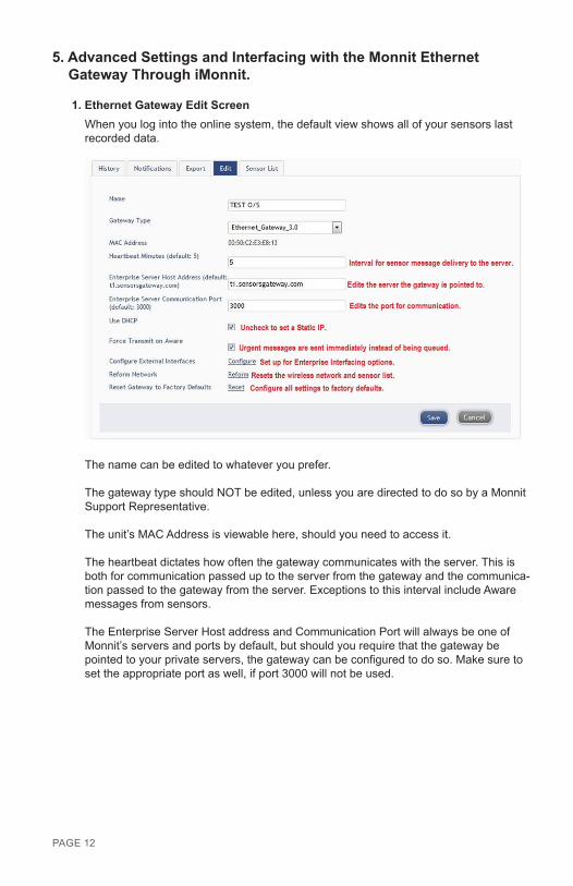
1. Ethernet Gateway Edit ScreenWhen you log into the online system, the default view shows all of your sensors last recorded data.
The name can be edited to whatever you prefer.
The gateway type should NOT be edited, unless you are directed to do so by a Monnit Support Representative.
The unit’s MAC Address is viewable here, should you need to access it.
The heartbeat dictates how often the gateway communicates with the server. This is both for communication passed up to the server from the gateway and the communica-tion passed to the gateway from the server. Exceptions to this interval include Aware messages from sensors.
The Enterprise Server Host address and Communication Port will always be one of Monnit’s servers and ports by default, but should you require that the gateway be pointed to your private servers, the gateway can be configured to do so. Make sure to set the appropriate port as well, if port 3000 will not be used.
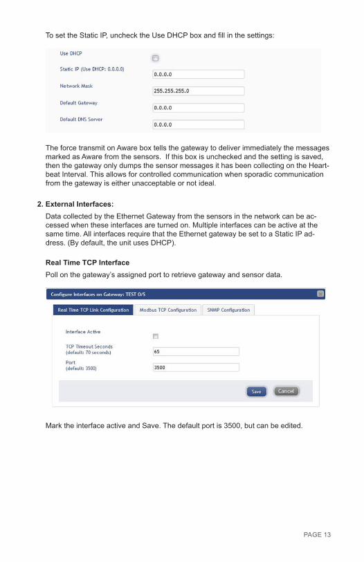
To set the Static IP, uncheck the Use DHCP box and fill in the settings:
The force transmit on Aware box tells the gateway to deliver immediately the messages marked as Aware from the sensors. If this box is unchecked and the setting is saved, then the gateway only dumps the sensor messages it has been collecting on the Heart-beat Interval. This allows for controlled communication when sporadic communication from the gateway is either unacceptable or not ideal.
2. External Interfaces: Data collected by the Ethernet Gateway from the sensors in the network can be ac-cessed when these interfaces are turned on. Multiple interfaces can be active at the same time. All interfaces require that the Ethernet gateway be set to a Static IP ad-dress. (By default, the unit uses DHCP).
Real Time TCP InterfacePoll on the gateway’s assigned port to retrieve gateway and sensor data.
Mark the interface active and Save. The default port is 3500, but can be edited.
PAGE 13
PAGE 14
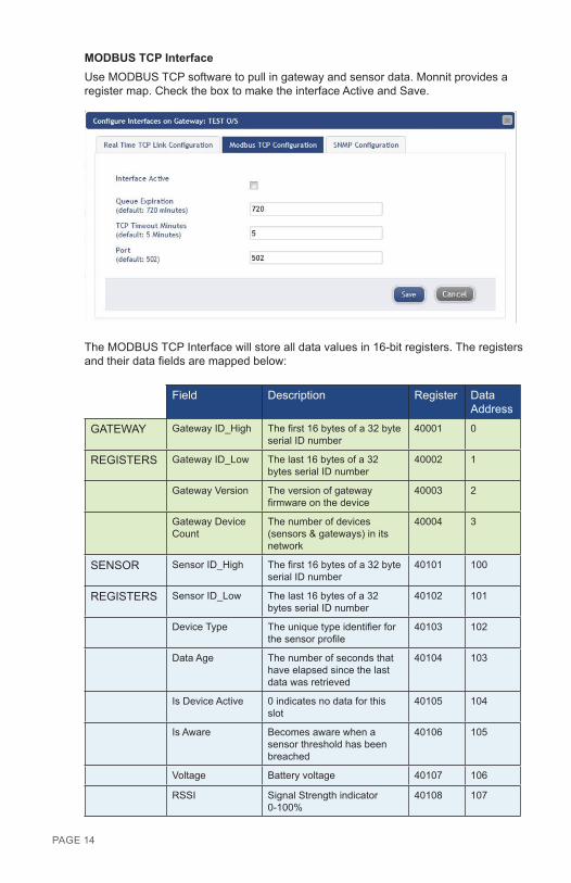
MODBUS TCP InterfaceUse MODBUS TCP software to pull in gateway and sensor data. Monnit provides a register map. Check the box to make the interface Active and Save.
The MODBUS TCP Interface will store all data values in 16-bit registers. The registers and their data fields are mapped below:
Field Description Register Data Address
GATEWAY Gateway ID_High The first 16 bytes of a 32 byte serial ID number
40001 0
REGISTERS Gateway ID_Low The last 16 bytes of a 32 bytes serial ID number
40002 1
Gateway Version The version of gateway firmware on the device
40003 2
Gateway Device Count
The number of devices (sensors & gateways) in its network
40004 3
SENSOR Sensor ID_High The first 16 bytes of a 32 byte serial ID number
40101 100
REGISTERS Sensor ID_Low The last 16 bytes of a 32 bytes serial ID number
40102 101
Device Type The unique type identifier for the sensor profile
40103 102
Data Age The number of seconds that have elapsed since the last data was retrieved
40104 103
Is Device Active 0 indicates no data for this slot
40105 104
Is Aware Becomes aware when a sensor threshold has been breached
40106 105
Voltage Battery voltage 40107 106
RSSI Signal Strength indicator 0-100%
40108 107

Data 1 Sensor Data Field 1 40109 108
Data 2 Sensor Data Field 2 40110 109
Data 3 Sensor Data Field 3 40111 110
Data 4 Sensor Data Field 4 40112 111
Data 5 Sensor Data Field 5 40113 112
Data 6 Sensor Data Field 6 40114 113
Data 7 Sensor Data Field 7 40115 114
Data 8 Sensor Data Field 8 40116 115
SNMP Poll and Trap InterfaceUse SNMP software to pull in gateway and sensor data. Monnit provides a .MIB file. There are four available interfaces. Set the SNMP Interface Address for each one the address of the device sending the SNMP request). Mark the interface Active and Save.
The MIB file is available through here: resources.monnit.com/content/downloads/MonnitEGW-MIB_v1
The MIB Tree looks like this:
PAGE 15
PAGE 16
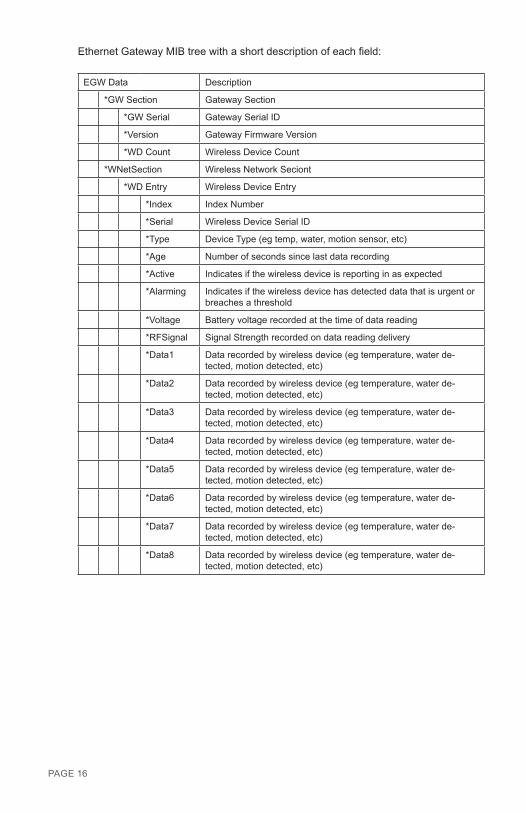
Ethernet Gateway MIB tree with a short description of each field:
EGW Data Description
*GW Section Gateway Section
*GW Serial Gateway Serial ID
*Version Gateway Firmware Version
*WD Count Wireless Device Count
*WNetSection Wireless Network Seciont
*WD Entry Wireless Device Entry
*Index Index Number
*Serial Wireless Device Serial ID
*Type Device Type (eg temp, water, motion sensor, etc)
*Age Number of seconds since last data recording
*Active Indicates if the wireless device is reporting in as expected
*Alarming Indicates if the wireless device has detected data that is urgent or breaches a threshold
*Voltage Battery voltage recorded at the time of data reading
*RFSignal Signal Strength recorded on data reading delivery
*Data1 Data recorded by wireless device (eg temperature, water de-tected, motion detected, etc)
*Data2 Data recorded by wireless device (eg temperature, water de-tected, motion detected, etc)
*Data3 Data recorded by wireless device (eg temperature, water de-tected, motion detected, etc)
*Data4 Data recorded by wireless device (eg temperature, water de-tected, motion detected, etc)
*Data5 Data recorded by wireless device (eg temperature, water de-tected, motion detected, etc)
*Data6 Data recorded by wireless device (eg temperature, water de-tected, motion detected, etc)
*Data7 Data recorded by wireless device (eg temperature, water de-tected, motion detected, etc)
*Data8 Data recorded by wireless device (eg temperature, water de-tected, motion detected, etc)
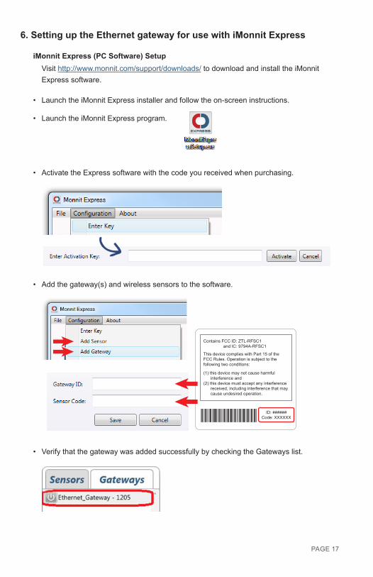
6. Setting up the Ethernet gateway for use with iMonnit Express
iMonnit Express (PC Software) SetupVisit http://www.monnit.com/support/downloads/ to download and install the iMonnit Express software.
• Launch the iMonnit Express installer and follow the on-screen instructions.
• Launch the iMonnit Express program.
• Activate the Express software with the code you received when purchasing.
• Add the gateway(s) and wireless sensors to the software.
Contains FCC ID: ZTL-RFSC1 and IC: 9794A-RFSC1
This device complies with Part 15 of the FCC Rules. Operation is subject to the following two conditions:
(1) this device may not cause harmful interference and (2) this device must accept any interference received, including interference that may cause undesired operation.
ID: ######Code: XXXXXX
• Verify that the gateway was added successfully by checking the Gateways list.
PAGE 17
PAGE 18
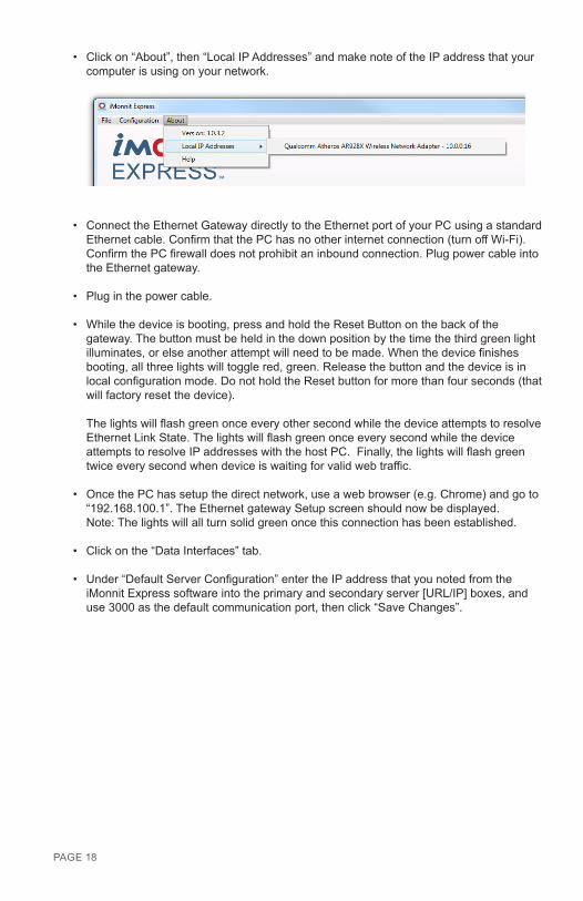
• Click on “About”, then “Local IP Addresses” and make note of the IP address that your computer is using on your network.
• Connect the Ethernet Gateway directly to the Ethernet port of your PC using a standard Ethernet cable. Confirm that the PC has no other internet connection (turn off Wi-Fi). Confirm the PC firewall does not prohibit an inbound connection. Plug power cable into the Ethernet gateway.
• Plug in the power cable.
• While the device is booting, press and hold the Reset Button on the back of the gateway. The button must be held in the down position by the time the third green light illuminates, or else another attempt will need to be made. When the device finishes booting, all three lights will toggle red, green. Release the button and the device is in local configuration mode. Do not hold the Reset button for more than four seconds (that will factory reset the device). The lights will flash green once every other second while the device attempts to resolve Ethernet Link State. The lights will flash green once every second while the device attempts to resolve IP addresses with the host PC. Finally, the lights will flash green twice every second when device is waiting for valid web traffic.
• Once the PC has setup the direct network, use a web browser (e.g. Chrome) and go to “192.168.100.1”. The Ethernet gateway Setup screen should now be displayed. Note: The lights will all turn solid green once this connection has been established.
• Click on the “Data Interfaces” tab.
• Under “Default Server Configuration” enter the IP address that you noted from the iMonnit Express software into the primary and secondary server [URL/IP] boxes, and use 3000 as the default communication port, then click “Save Changes”.
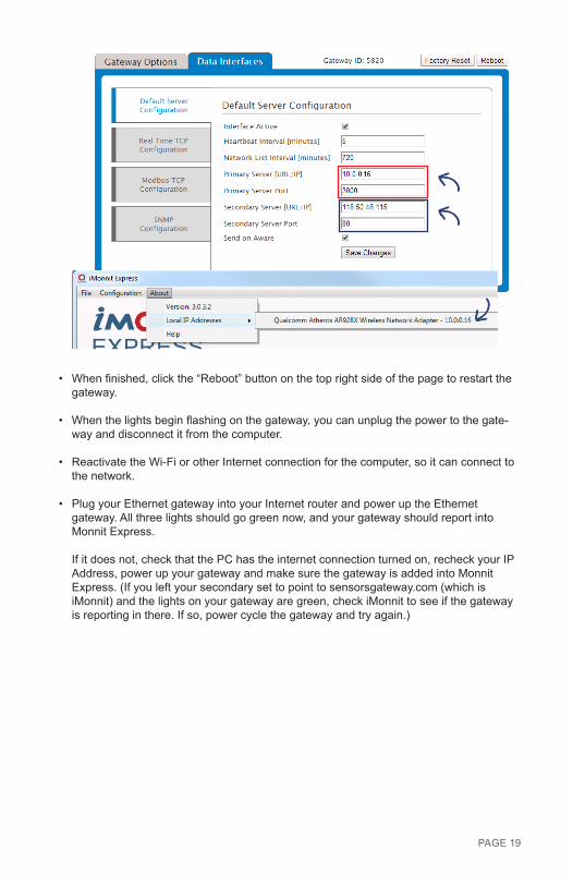
• When finished, click the “Reboot” button on the top right side of the page to restart the gateway.
• When the lights begin flashing on the gateway, you can unplug the power to the gate-way and disconnect it from the computer.
• Reactivate the Wi-Fi or other Internet connection for the computer, so it can connect to the network.
• Plug your Ethernet gateway into your Internet router and power up the Ethernet gateway. All three lights should go green now, and your gateway should report into Monnit Express. If it does not, check that the PC has the internet connection turned on, recheck your IP Address, power up your gateway and make sure the gateway is added into Monnit Express. (If you left your secondary set to point to sensorsgateway.com (which is iMonnit) and the lights on your gateway are green, check iMonnit to see if the gateway is reporting in there. If so, power cycle the gateway and try again.)
PAGE 19
Error Reporting, Troubleshooting and Support For technical support and troubleshooting tips please visit our support library online at http://www.monnit.com/support/. If you are unable to solve your issue using our online support, email Monnit support at [email protected] with your contact information and a description of the problem, and a support representative will call you within one business day.
For error reporting, please email a full description of the error to [email protected].
Warranty Information (a) Monnit warrants that Monnit-branded products will be free from defects in materials and workmanship for a period of one (1) year from the date of delivery with respect to hardware and will materially conform to their published specifications for a period of one (1) year with respect to software. Monnit may resell sensors manufactured by other entities and are subject to their individual warranties; Monnit will not enhance or extend those warranties. Monnit does not warrant that the software or any portion thereof is error free. Monnit will have no warranty obligation with respect to Products subjected to abuse, misuse, negli-gence or accident. If any software or firmware incorporated in any Product fails to conform to the warranty set forth in this Section, Monnit shall provide a bug fix or software patch correcting such non-conformance within a reasonable period after Monnit receives from Customer (i) notice of such non-conformance, and (ii) sufficient information regarding such non-conformance so as to permit Monnit to create such bug fix or software patch. If any hardware component of any Product fails to conform to the warranty in this Section, Monnit shall, at its option, refund the purchase price less any discounts, or repair or replace non-conforming Products with conforming Products or Products having substantially identical form, fit, and function and deliver the repaired or replacement Product to a carrier for land shipment to customer within a reasonable period after Monnit receives from Customer (i) notice of such non-conformance, and (ii) the non-conforming Product provided; however, if, in its opinion, Monnit cannot repair or replace on commercially reasonable terms it may choose to refund the purchase price. Repair parts and replacement products may be reconditioned or new. All replacement products and parts become the property of Monnit. Repaired or replacement products shall be subject to the warranty, if any remains, originally applicable to the product repaired or replaced. Customer must obtain from Monnit a Return Material Authorization Number (RMA) prior to returning any Products to Monnit. Products returned under this Warranty must be unmodified.
Customer may return all Products for repair or replacement due to defects in original mate-rials and workmanship if Monnit is notified within ninety (90) days of customer’s receipt of the product. Monnit reserves the right to repair or replace products at its own and complete discretion. Customer must obtain from Monnit a Return Material Authorization Number (RMA) prior to returning any products to Monnit. Products returned under this Warranty must be unmodified and in original packaging. Monnit reserves the right to refuse warranty repairs or replacements for any products that are damaged or not in original form. For products outside the ninety-day warranty period repair services are available at Monnit at standard labor rates for a period of one year from the Customer’s original date of receipt.
PAGE 20

(b) As a condition to Monnit’s obligations under the immediately preceding paragraphs, Customer shall return Products to be examined and replaced to Monnit’s facilities, in shipping cartons which clearly display a valid RMA number provided by Monnit. Customer acknowledges that replacement products may be repaired, refurbished or tested and found to be complying. Customer shall bear the risk of loss for such return shipment and shall bear all shipping costs. Monnit shall deliver replacements for Products determined by Mon-nit to be properly returned, shall bear the risk of loss and such costs of shipment of repaired products or replacements, and shall credit Customer’s reasonable costs of shipping such returned Products against future purchases.
(c) Monnit’s sole obligation under the warranty described or set forth here shall be to repair or replace non-conforming products as set forth in the immediately preceding paragraph, or to refund the documented purchase price for non-conforming Products to Customer. Mon-nit’s warranty obligations shall run solely to Customer, and Monnit shall have no obligation to customers of Customer or other users of the Products.
Limitation of Warranty and Remedies.
THE WARRANTY SET FORTH HEREIN IS THE ONLY WARRANTY APPLICABLE TO PRODUCTS PURCHASED BY CUSTOMER. ALL OTHER WARRANTIES, EXPRESS OR IMPLIED, INCLUDING BUT NOT LIMITED TO THE IMPLIED WARRANTIES OF MERCHANTABILITY AND FITNESS FOR A PARTICULAR PURPOSE ARE EXPRESSLY DISCLAIMED. MONNIT’S LIABIITY WHETHER IN CONTRACT, IN TORT, UNDER ANY WARRANTY, IN NEGLIGENCE OR OTHERWISE SHALL NOT EXCEED THE PURCHASE PRICE PAID BY CUSTOMER FOR THE PRODUCT. UNDER NO CIRCUMSTANCES SHALL MONNIT BE LIABLE FOR SPECIAL, INDIRECT OR CONSEQUENTIAL DAM-AGES. THE PRICE STATED FOR THE PRODUCTS IS A CONSIDERATION IN LIMITING MONNIT’S LIABILITY. NO ACTION, REGARDLESS OF FORM, ARISING OUT OF THIS AGREEMENT MAY BE BROUGHT BY CUSTOMER MORE THAN ONE YEAR AFTER THE CAUSE OF ACTION HAS ACCRUED.
IN ADDITION TO THE WARRANTIES DISCLAIMED ABOVE, MONNIT SPECIFICALLY DISCLAIMS ANY AND ALL LIABILITY AND WARRANTIES, IMPLIED OR EXPRESSED, FOR USES REQUIRING FAIL-SAFE PERFORMANCE IN WHICH FAILURE OF A PROD-UCT COULD LEAD TO DEATH, SERIOUS PERSONAL INJURY, OR SEVERE PHYSICAL OR ENVIRONMENTAL DAMAGE SUCH AS, BUT NOT LIMITED TO, LIFE SUPPORT OR MEDICAL DEVICES OR NUCLEAR APPLICATIONS. PRODUCTS ARE NOT DESIGNED FOR AND SHOULD NOT BE USED IN ANY OF THESE APPLICATIONS.
PAGE 21
CertificationsUnited States FCC This equipment has been tested and found to comply with the limits for a Class B digital devices, pursuant to Part 15 of the FCC Rules. These limits are designed to provide reasonable protection against harmful interference in a residential installation. This equipment generates, uses, and can radiate radio frequency energy and, if not installed and used in accordance with the instruction manual, may cause harmful interference to radio communications. However, there is no guarantee that interference will not occur in a particular installation. If this equipment does cause harmful interference to radio or television reception, which can be determined by turning the equipment off and on, the user is encouraged to try to correct the interference by one of more of the following measures:
• Reorient or relocate the receiving antenna • Increase the separation between the equipment and receiver • Connect the equipment into an outlet on a circuit different from that to which the receiver is connected. • Consult the dealer or an experienced radio/TV technician for help.
Warning: Changes or modifications not expressly approved by Monnit could void the user’s authority to operate the equipment.
RF Exposure
Monnit Wireless Sensors and Ethernet Gateway Contain: FCC ID: ZTL-RFSC1 This device has been designed to operate with an approved antenna listed below, and having a maximum gain of 5.1 dBi. Antennas not included in this list or having a gain greater than 5.1 dBi are strictly prohibited for use with this device. The required antenna impedance is 50 ohms. To reduce potential radio interference to other users, the antenna type and its gain should be so chosen that the equivalent isotropically radiated power (EIRP) is not more than that required for successful communication.
Approved Antennas The following antennas are approved for use with Monnit devices. • Hyperlink HG905RD-RSP (5.1 dBi Rubber Duck) • Pulse W1063 (3.0 dBi Rubber Duck) • ChangHong GSM-09 (2.0 dBi Rubber Duck) • Specialized Manufacturing MC-ANT-20/4.0C (4” whip)
WARNING: To satisfy FCC RF exposure requirements for mobile transmitting devices, the antenna used for this transmitter must not be co-located in conjunction with any other antenna or transmitter.
PAGE 22
IndustryCanada

PAGE 23
Canada (IC) EnglishUnder Industry Canada regulations, this radio transmitter may only operate using an antenna of a type and maximum (or lesser) gain approved for the transmitter by Industry Canada. To reduce potential radio interference to other users, the antenna type and its gain should be so chosen that the equivalent isotropically radiated power (e.i.r.p.) is not more than that necessary for successful communication. The radio transmitter (IC: 9794A-RFSC1) has been approved by Industry Canada to oper-ate with the antenna types listed below with the maximum permissible gain and required antenna impedance for each antenna type indicated. Antenna types not included in this list, having a gain greater than the maximum gain indicated for that type, are strictly prohibited for use with this device. This device complies with Industry Canada licence-exempt RSS standard(s). Operation is subject to the following two conditions: (1) this device may not cause interference, and (2) this device must accept any interference, including interference that may cause undesired operation of the device.
FrenchConformément à la réglementation d’Industrie Canada, le présent émetteur radio peut fonctionner avec une antenne d’un type et d’un gain maximal (ou inférieur) approuvé pour l’émetteur par Industrie Canada. Dans le but de réduire les risques de brouillage radioélec-trique à l’intention des autres utilisateurs, il faut choisir le type d’antenne et son gain de sorte que la puissance isotrope rayonnée équivalente (p.i.r.e.) ne dépasse pas l’intensité nécessaire à l’établissement d’une communication satisfaisante. Le présent émetteur radio (IC: 9794A-RFSC1) a été approuvé par Industrie Canada pour fonctionner avec les types d’antenne énumérés ci-dessous et ayant un gain admissible maximal et l’impédance requise pour chaque type d’antenne. Les types d’antenne non inc-lus dans cette liste, ou dont le gain est supérieur au gain maximal indiqué, sont strictement interdits pour l’exploitation de l’émetteur. Le présent appareil est conforme aux CNR d’Industrie Canada applicables aux appareils radio exempts de licence. L’exploitation est autorisée aux deux conditions suivantes : (1) l’appareil ne doit pas produire de brouillage, et (2) l’utilisateur de l’appareil doit accepter tout brouillage radioélectrique subi, méme si le brouillage est susceptible d’en comprom-ettre le fonctionnement.
Japan (ARIB) All Monnit 920 MHz products have been tested and found to comply with ARIB STD-T108 standards.
R 210-103733

MUG-22-2C (09/15)
Additional Information and Support
For additional information or more detailed instructions on how to use your Monnit Wireless Sensors or the iMonnit Online System, please visit us on the web at http://www.monnit.com/support/.
Monnit Corporation4403 South 500 WestMurray, UT 84123801-561-5555www.monnit.com
Monnit, Monnit Logo and all other trademarks are property of Monnit, Corp. © 2009-2015 Monnit Corp. All Rights Reserved.