Embed Size (px)
Citation preview
Marc Sarazin, G. Lombardi, J. Navarrete, A. Tokovinin, R. Wilson ESO Garching, ESO Paranal
CTIO La Serena, Durham University
Monitoring Site Parameters for AO
1 Victoria 2011
ABSTRACT The various ELT project have deployed a very uniform instrumentation suite, often using similar measurement methods (DIMM) and even in some cases identical instruments (MASS). A review is proposed of what has been achieved and what is now available, and the compatibility with the requirements from AO is examined
Monitoring Site Parameters for AO
2 Victoria 2011
3
Victoria 2011
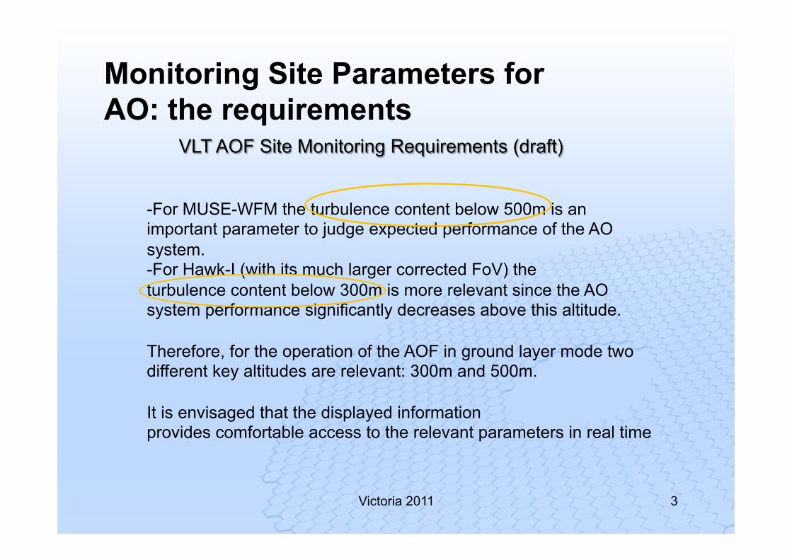
-For MUSE-WFM the turbulence content below 500m is an important parameter to judge expected performance of the AO system. -For Hawk-I (with its much larger corrected FoV) the turbulence content below 300m is more relevant since the AO system performance significantly decreases above this altitude. Therefore, for the operation of the AOF in ground layer mode two different key altitudes are relevant: 300m and 500m. It is envisaged that the displayed information provides comfortable access to the relevant parameters in real time
VLT AOF Site Monitoring Requirements (draft)
Monitoring Site Parameters for AO: the requirements
4
Victoria 2011
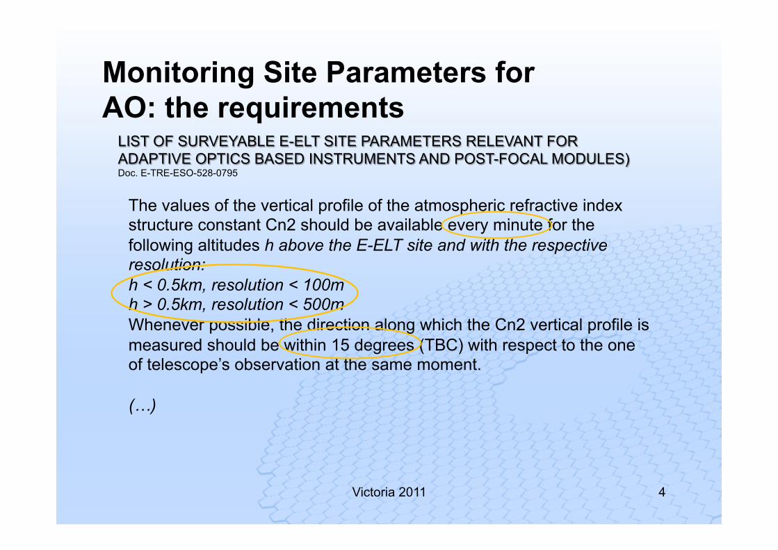
The values of the vertical profile of the atmospheric refractive index structure constant Cn2 should be available every minute for the following altitudes h above the E-ELT site and with the respective resolution: h < 0.5km, resolution < 100m h > 0.5km, resolution < 500m Whenever possible, the direction along which the Cn2 vertical profile is measured should be within 15 degrees (TBC) with respect to the one of telescope’s observation at the same moment. (…)
LIST OF SURVEYABLE E-ELT SITE PARAMETERS RELEVANT FOR ADAPTIVE OPTICS BASED INSTRUMENTS AND POST-FOCAL MODULES) Doc. E-TRE-ESO-528-0795
Monitoring Site Parameters for AO: the requirements
5
Victoria 2011
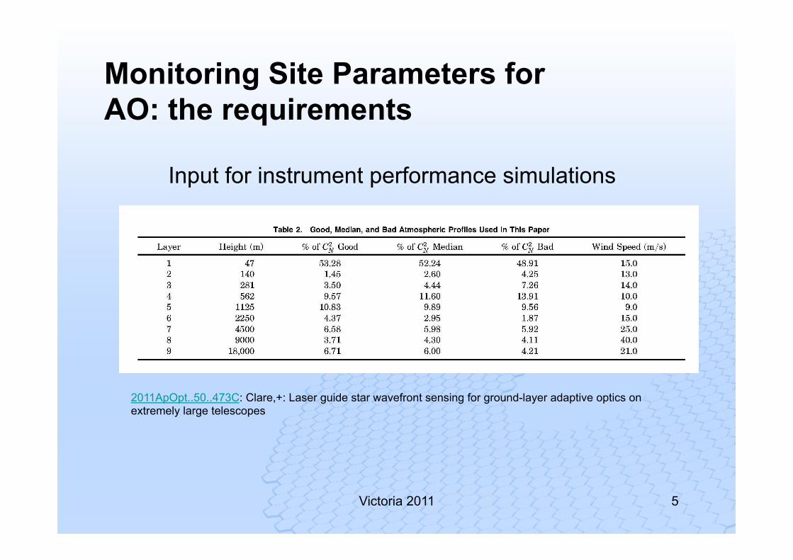
2011ApOpt..50..473C: Clare,+: Laser guide star wavefront sensing for ground-layer adaptive optics on extremely large telescopes
Monitoring Site Parameters for AO: the requirements
Input for instrument performance simulations
6
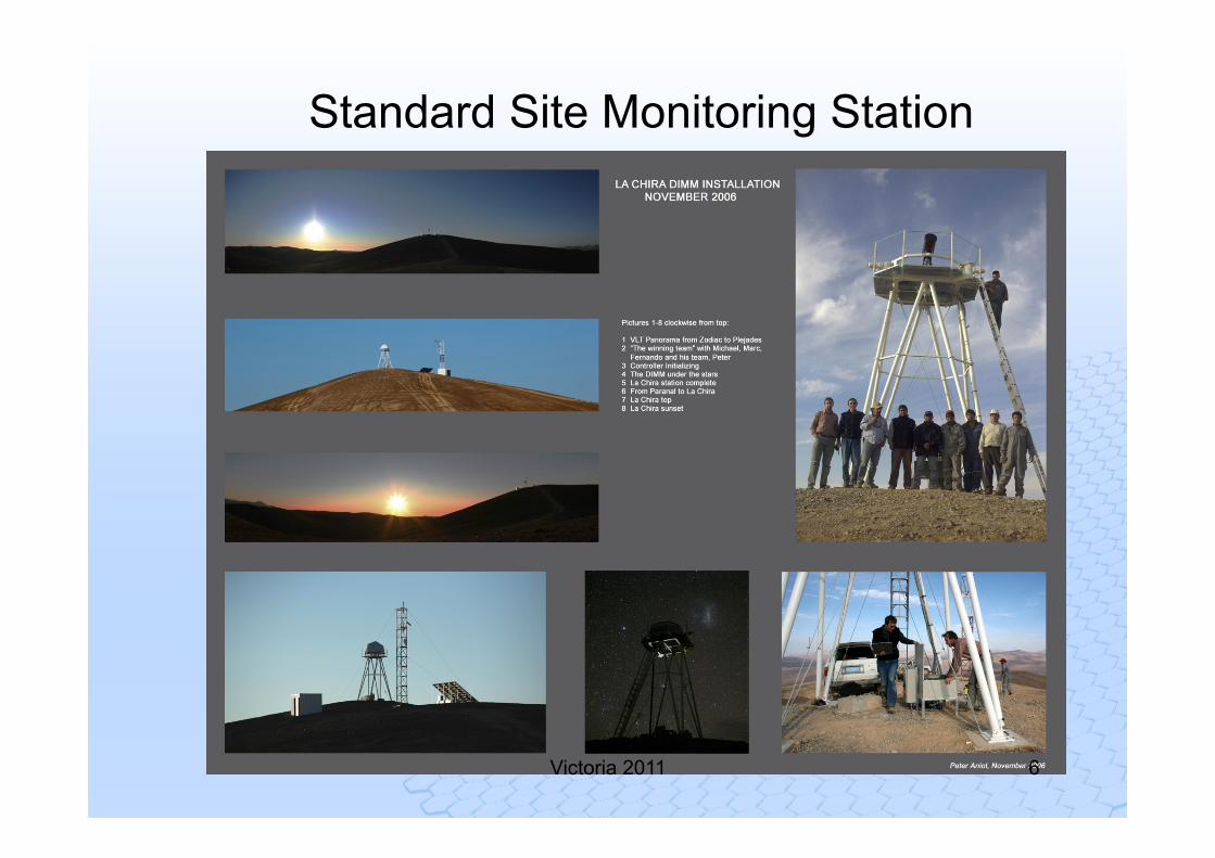
Standard Site Monitoring Station
Victoria 2011
Working Together
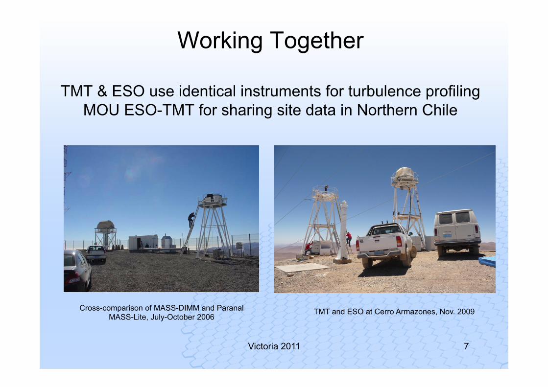
TMT & ESO use identical instruments for turbulence profiling MOU ESO-TMT for sharing site data in Northern Chile
7 Victoria 2011
TMT and ESO at Cerro Armazones, Nov. 2009 Cross-comparison of MASS-DIMM and Paranal MASS-Lite, July-October 2006
MASS-DIMM
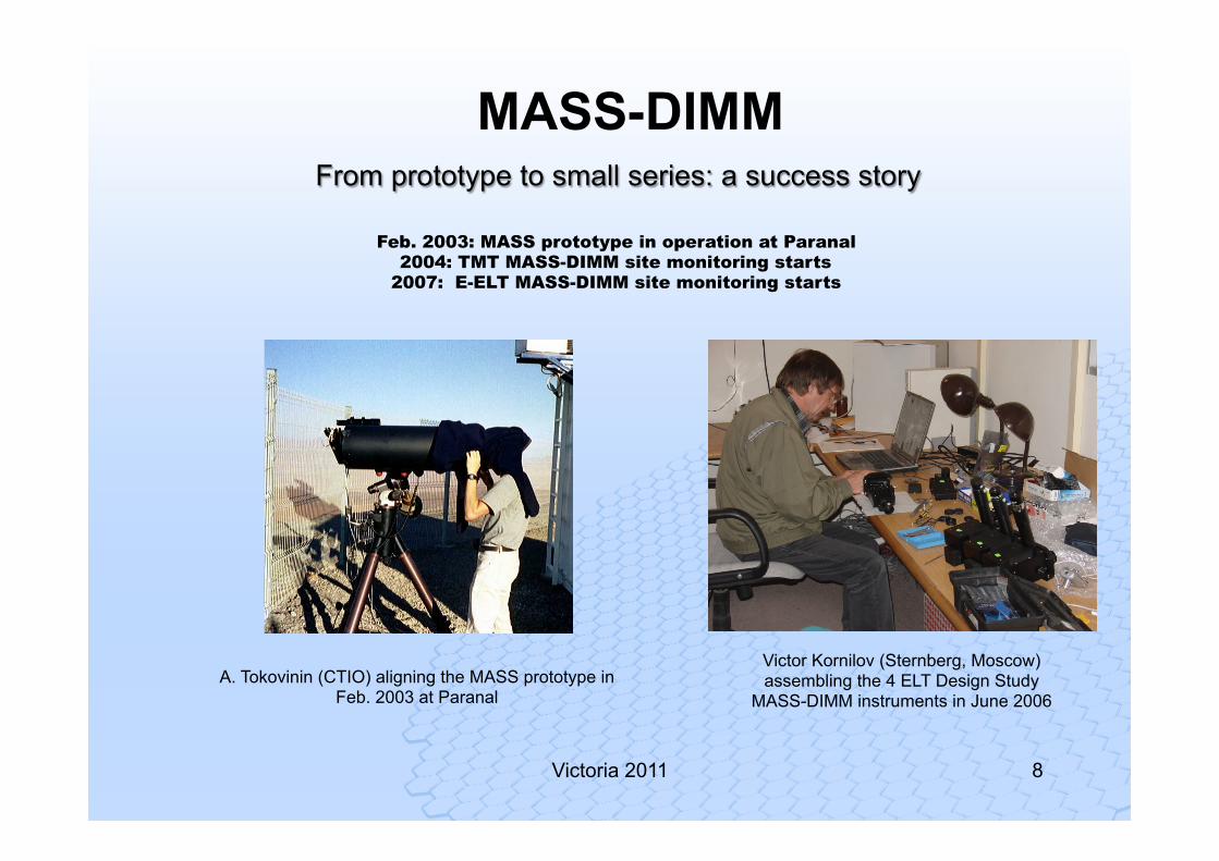
Victor Kornilov (Sternberg, Moscow) assembling the 4 ELT Design Study
MASS-DIMM instruments in June 2006
Feb. 2003: MASS prototype in operation at Paranal 2004: TMT MASS-DIMM site monitoring starts
2007: E-ELT MASS-DIMM site monitoring starts
A. Tokovinin (CTIO) aligning the MASS prototype in Feb. 2003 at Paranal
Victoria 2011 8
From prototype to small series: a success story
9 Victoria 2011
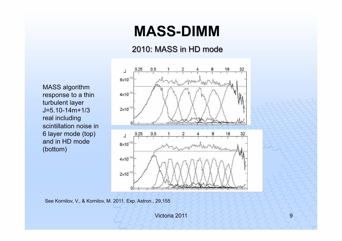
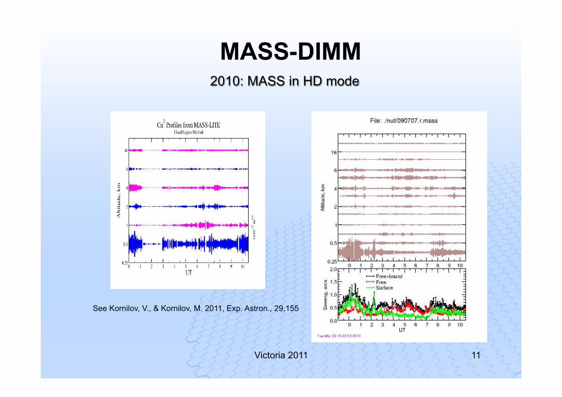
See Kornilov, V., & Kornilov, M. 2011, Exp. Astron., 29,155
MASS algorithm response to a thin turbulent layer J=5.10-14m+1/3 real including scintillation noise in 6 layer mode (top) and in HD mode (bottom)
MASS-DIMM 2010: MASS in HD mode
MASS-DIMM Reprocessing MASS database in HD mode
Victoria 2011 10
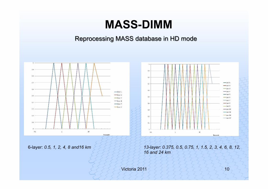
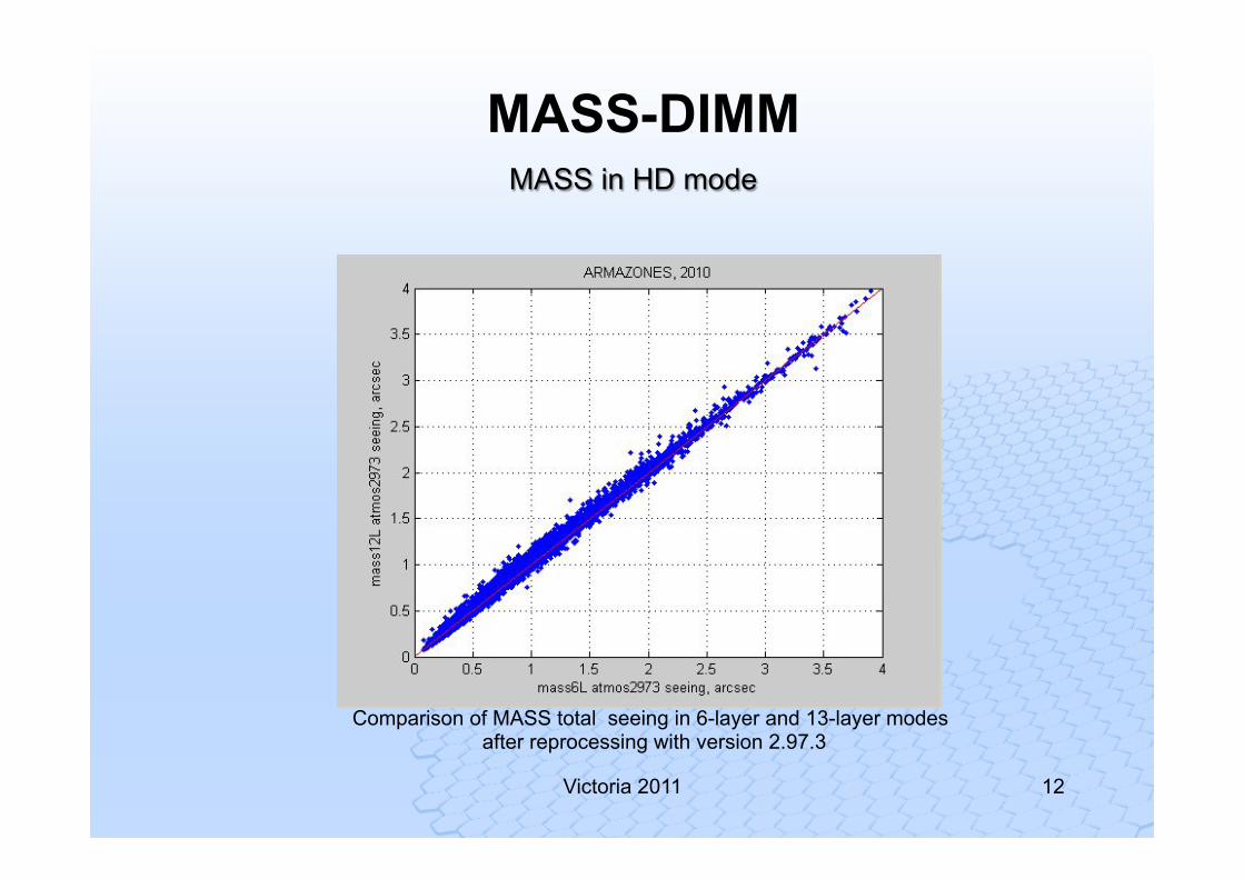
13-layer: 0.375, 0.5, 0.75, 1, 1.5, 2, 3, 4, 6, 8, 12, 16 and 24 km
6-layer: 0.5, 1, 2, 4, 8 and16 km
MASS-DIMM 2010: MASS in HD mode
Victoria 2011 11
See Kornilov, V., & Kornilov, M. 2011, Exp. Astron., 29,155
12 Victoria 2011
Comparison of MASS total seeing in 6-layer and 13-layer modes after reprocessing with version 2.97.3
MASS in HD mode
MASS-DIMM
13 Victoria 2011
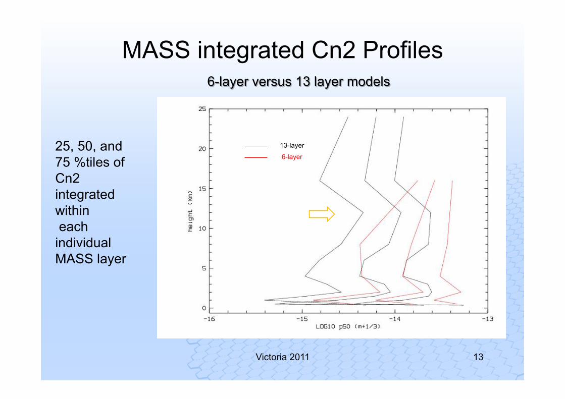
25, 50, and 75 %tiles of Cn2 integrated within each individual MASS layer
6-layer versus 13 layer models
13-layer
6-layer
MASS integrated Cn2 Profiles

14 Victoria 2011
25, 50, and 75 %tiles of Cn2 integrated within each individual MASS layer
6-layer versus 13 layer models
13-layer
6-layer
MASS integrated Cn2 Profiles
15 Victoria 2011
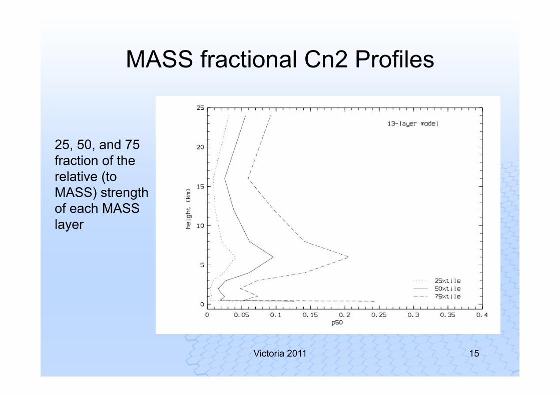
25, 50, and 75 fraction of the relative (to MASS) strength of each MASS layer
MASS fractional Cn2 Profiles
16 Victoria 2011
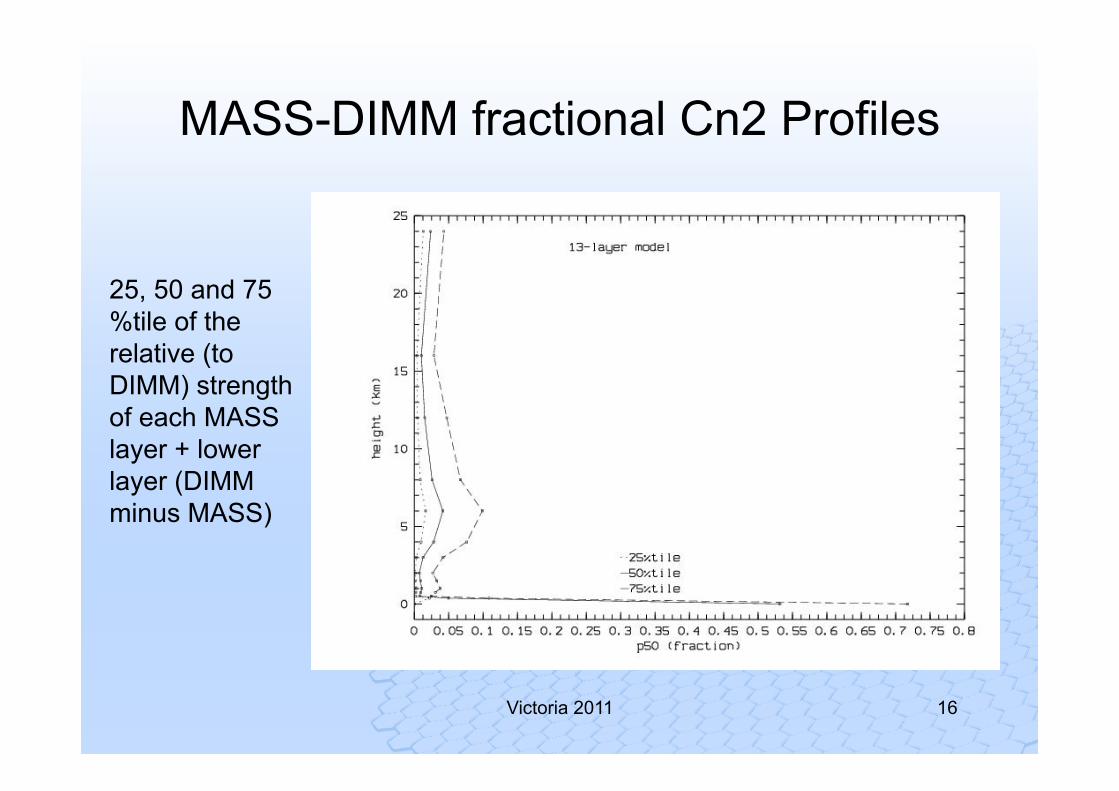
MASS-DIMM fractional Cn2 Profiles
25, 50 and 75 %tile of the relative (to DIMM) strength of each MASS layer + lower layer (DIMM minus MASS)
17 Victoria 2011
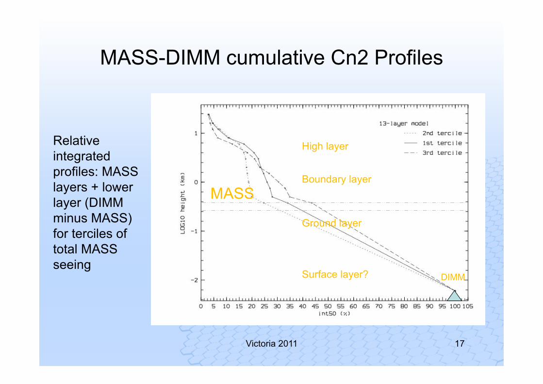
MASS-DIMM cumulative Cn2 Profiles
Relative integrated profiles: MASS layers + lower layer (DIMM minus MASS) for terciles of total MASS seeing
MASS
DIMM
High layer
Boundary layer
Ground layer
Surface layer?
18 Victoria 2011
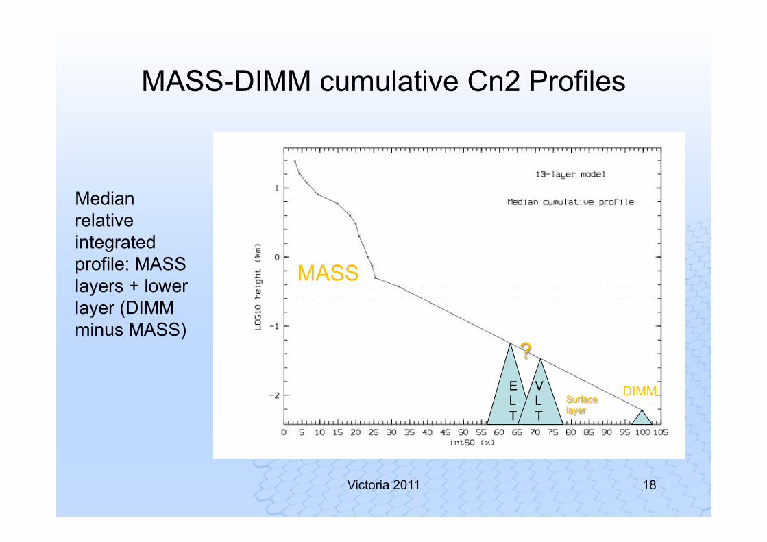
MASS-DIMM cumulative Cn2 Profiles
Surface layer
MASS
DIMM ELT
VLT
?
Median relative integrated profile: MASS layers + lower layer (DIMM minus MASS)
19 Victoria 2011
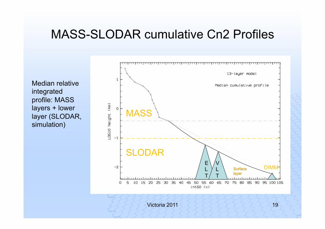
MASS-SLODAR cumulative Cn2 Profiles
Median relative integrated profile: MASS layers + lower layer (SLODAR, simulation)
Surface layer
SLODAR DIMM
ELT
VLT
MASS

ESO education and Public Outreach | 26.11.2008
Surface-Layer SLODAR
Automated Surface-Layer SLODAR Instrument at Paranal
Example Surface Layer Profile Sequence (09/04/2011)
• Durham CfAI / ESO development (since 2004)
• Dual-Beam SH-WFS, 50cm telescope (2011)
• Optical turbulence profile in first 100m • Altitude resolution ~ 12m • + total turbulence strength
WFS on binaries,12 to 16 arcmin separation Same principle as used by MOAO with asterisms
ESO education and Public Outreach | 26.11.2008
21 Victoria 2011
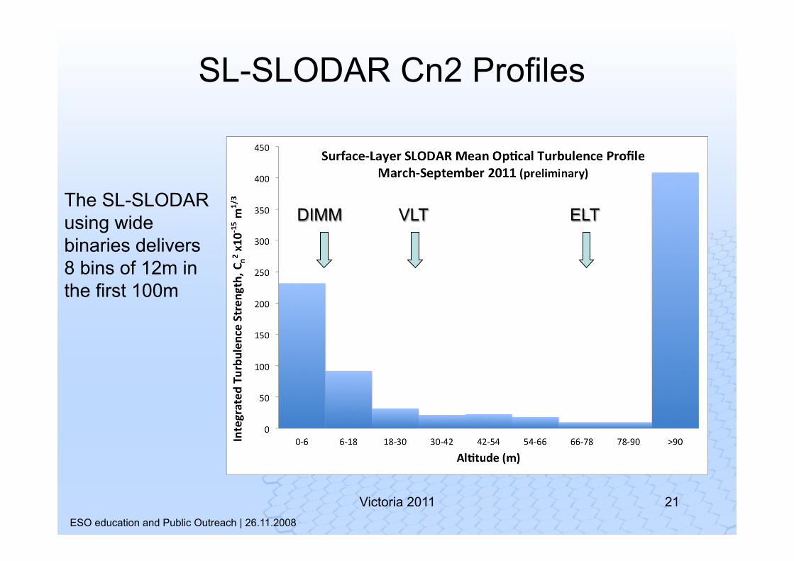
SL-SLODAR Cn2 Profiles
VLT ELT DIMM The SL-SLODAR using wide binaries delivers 8 bins of 12m in the first 100m
ESO education and Public Outreach | 26.11.2008
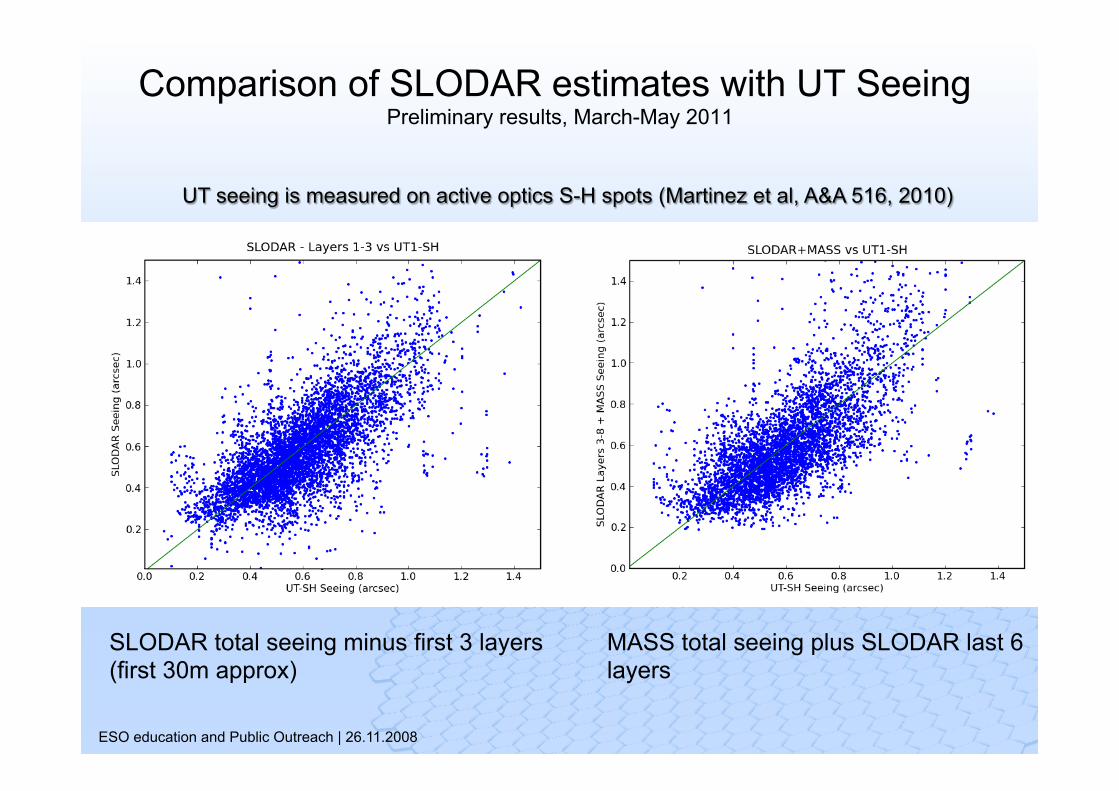
Comparison of SLODAR estimates with UT Seeing Preliminary results, March-May 2011
SLODAR total seeing minus first 3 layers (first 30m approx)
MASS total seeing plus SLODAR last 6 layers
UT seeing is measured on active optics S-H spots (Martinez et al, A&A 516, 2010)
23 Victoria 2011
Intermezzo: Taylor or not Taylor?
Is it feasible to predict the turbulence profile from stations a few km upwind?
24 Victoria 2011
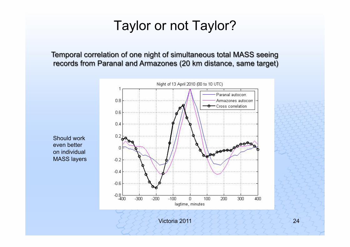
Taylor or not Taylor?
Should work even better on individual MASS layers
Temporal correlation of one night of simultaneous total MASS seeing records from Paranal and Armazones (20 km distance, same target)
ESO education and Public Outreach | 26.11.2008
25
Victoria 2011
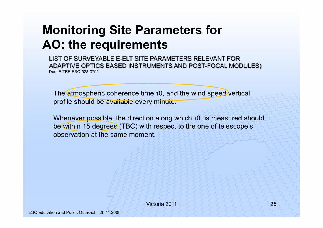
The atmospheric coherence time τ0, and the wind speed vertical profile should be available every minute: Whenever possible, the direction along which τ0 is measured should be within 15 degrees (TBC) with respect to the one of telescope’s observation at the same moment.
LIST OF SURVEYABLE E-ELT SITE PARAMETERS RELEVANT FOR ADAPTIVE OPTICS BASED INSTRUMENTS AND POST-FOCAL MODULES) Doc. E-TRE-ESO-528-0795
Monitoring Site Parameters for AO: the requirements
26 Victoria 2011
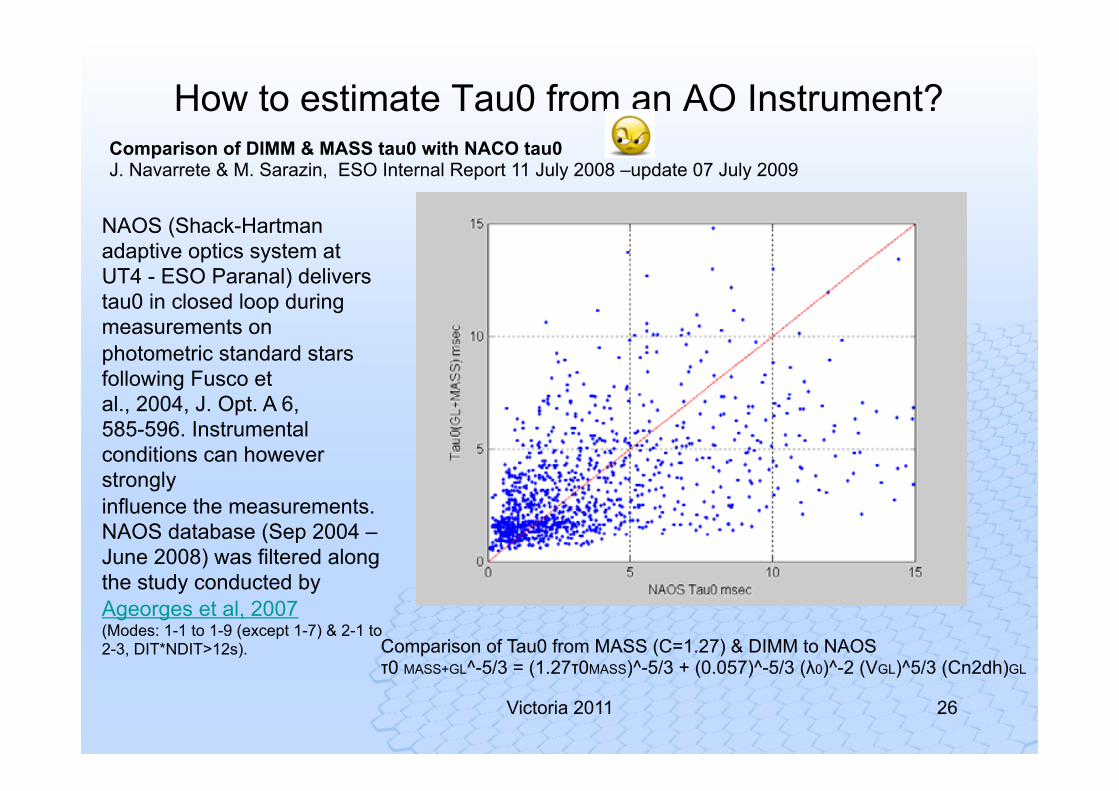
Comparison of Tau0 from MASS (C=1.27) & DIMM to NAOS τ0 MASS+GL^-5/3 = (1.27τ0MASS)^-5/3 + (0.057)^-5/3 (λ0)^-2 (VGL)^5/3 (Cn2dh)GL
NAOS (Shack-Hartman adaptive optics system at UT4 - ESO Paranal) delivers tau0 in closed loop during measurements on photometric standard stars following Fusco et al., 2004, J. Opt. A 6, 585-596. Instrumental conditions can however strongly influence the measurements. NAOS database (Sep 2004 – June 2008) was filtered along the study conducted by Ageorges et al, 2007 (Modes: 1-1 to 1-9 (except 1-7) & 2-1 to 2-3, DIT*NDIT>12s).
Comparison of DIMM & MASS tau0 with NACO tau0 J. Navarrete & M. Sarazin, ESO Internal Report 11 July 2008 –update 07 July 2009
How to estimate Tau0 from an AO Instrument?
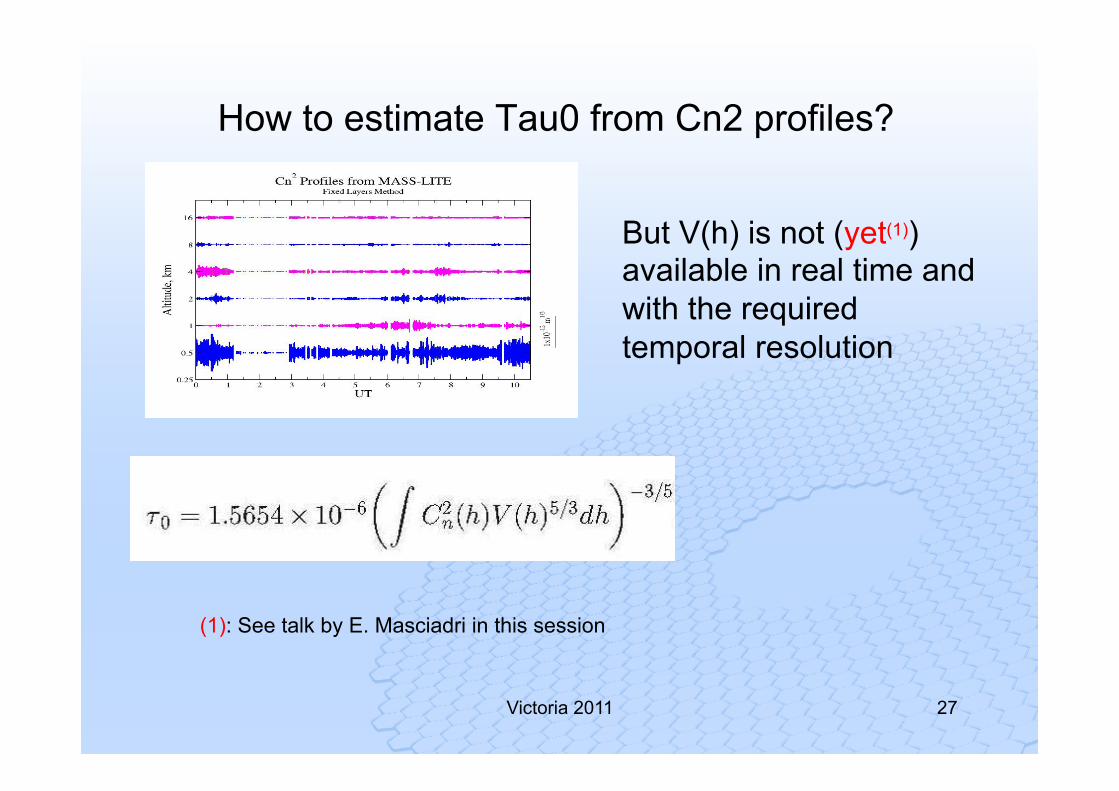
How to estimate Tau0 from Cn2 profiles?
27 Victoria 2011
But V(h) is not (yet(1)) available in real time and with the required temporal resolution
(1): See talk by E. Masciadri in this session
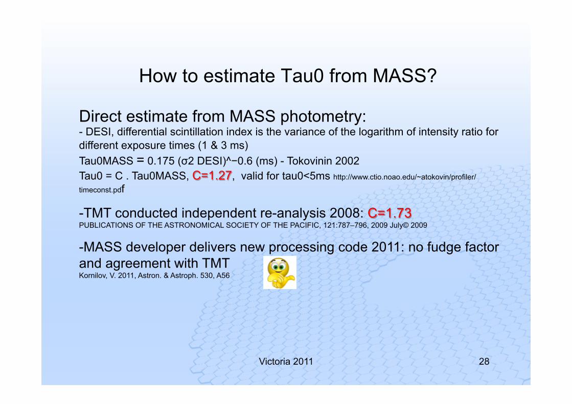
How to estimate Tau0 from MASS?
28 Victoria 2011
Direct estimate from MASS photometry: - DESI, differential scintillation index is the variance of the logarithm of intensity ratio for different exposure times (1 & 3 ms) Tau0MASS = 0.175 (σ2 DESI)^−0.6 (ms) - Tokovinin 2002 Tau0 = C . Tau0MASS, C=1.27, valid for tau0<5ms http://www.ctio.noao.edu/~atokovin/profiler/
timeconst.pdf
-TMT conducted independent re-analysis 2008: C=1.73 PUBLICATIONS OF THE ASTRONOMICAL SOCIETY OF THE PACIFIC, 121:787–796, 2009 July© 2009
-MASS developer delivers new processing code 2011: no fudge factor and agreement with TMT Kornilov, V. 2011, Astron. & Astroph. 530, A56
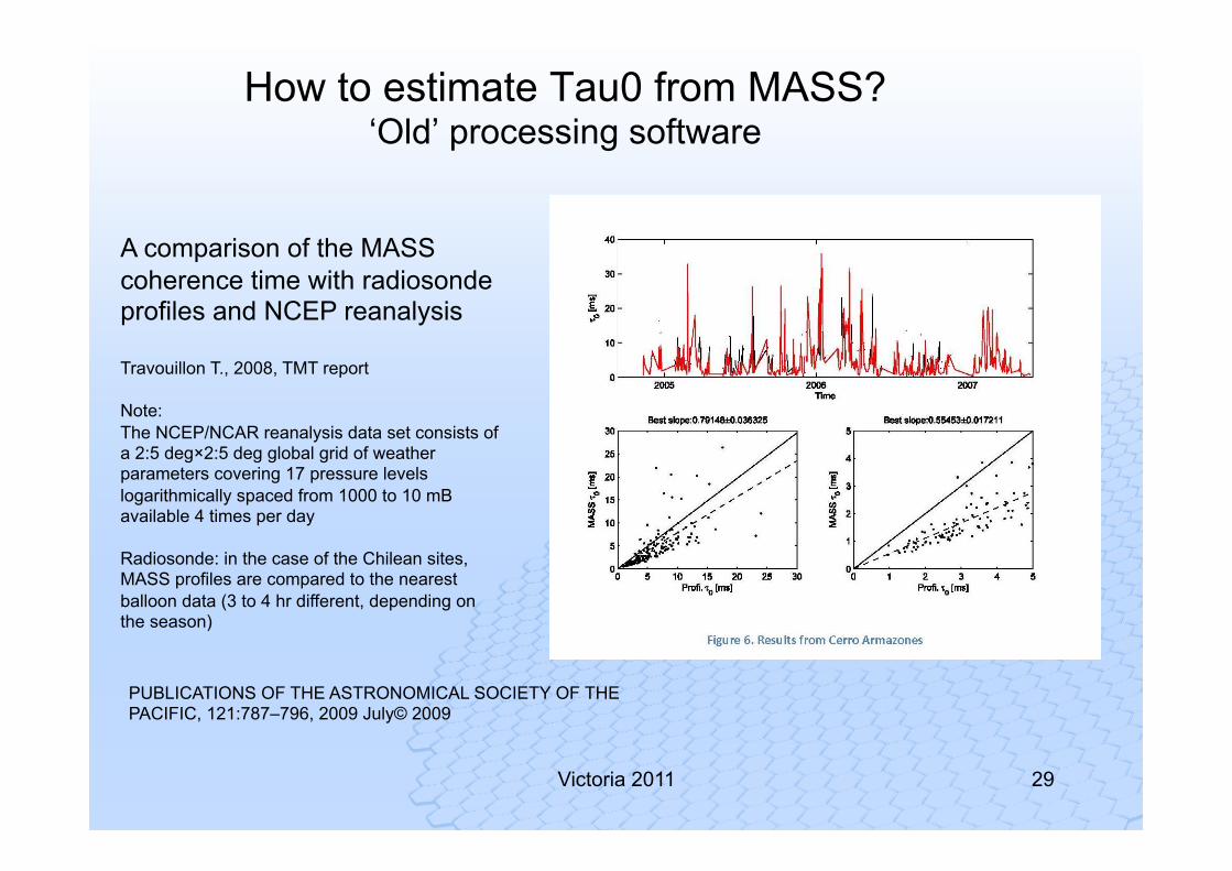
How to estimate Tau0 from MASS? ‘Old’ processing software
29 Victoria 2011
A comparison of the MASS coherence time with radiosonde profiles and NCEP reanalysis Travouillon T., 2008, TMT report Note: The NCEP/NCAR reanalysis data set consists of a 2:5 deg×2:5 deg global grid of weather parameters covering 17 pressure levels logarithmically spaced from 1000 to 10 mB available 4 times per day Radiosonde: in the case of the Chilean sites, MASS profiles are compared to the nearest balloon data (3 to 4 hr different, depending on the season)
PUBLICATIONS OF THE ASTRONOMICAL SOCIETY OF THE PACIFIC, 121:787–796, 2009 July© 2009
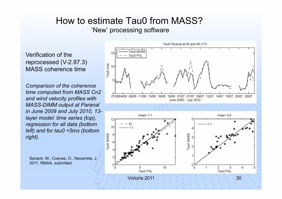
How to estimate Tau0 from MASS? ‘New’ processing software
30 Victoria 2011
Verification of the reprocessed (V-2.97.3) MASS coherence time Comparison of the coherence time computed from MASS Cn2 and wind velocity profiles with MASS-DIMM output at Paranal in June 2009 and July 2010, 13-layer model: time series (top), regression for all data (bottom left) and for tau0 <5ms (bottom right).
Sarazin, M., Cuevas, O., Navarrete, J. 2011, RMAA, submitted
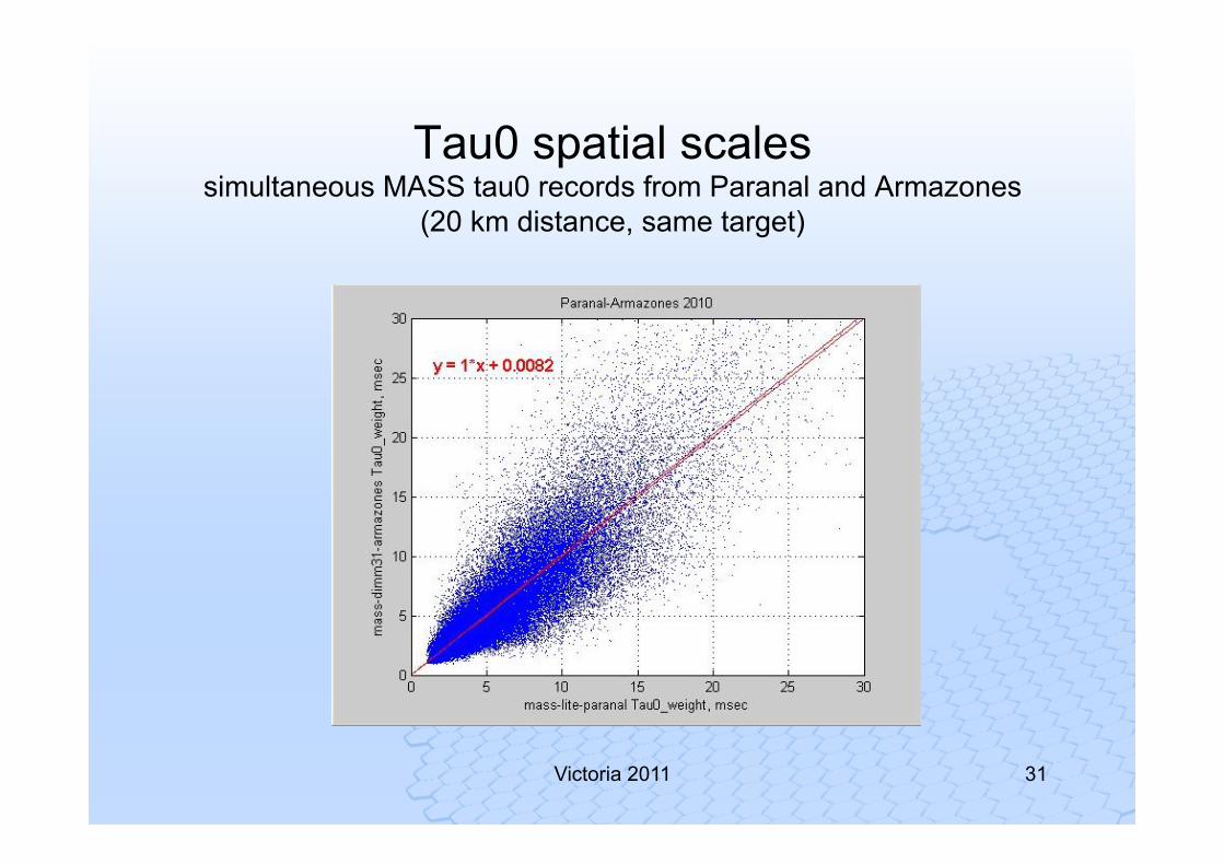
31 Victoria 2011
Tau0 spatial scales simultaneous MASS tau0 records from Paranal and Armazones
(20 km distance, same target)
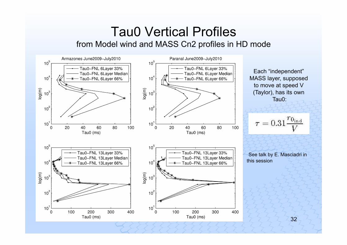
Tau0 Vertical Profiles from Model wind and MASS Cn2 profiles in HD mode
32 Victoria 2011
Each “independent”
MASS layer, supposed to move at speed V (Taylor), has its own
Tau0:
See talk by E. Masciadri in this session
33 Victoria 2011
How to estimate Tau0 from MASS?
Problem!
The ‘New’ MASS processing software does not consider the 5/3rd moment of the velocity but the 2nd
ESO education and Public Outreach | 26.11.2008
34
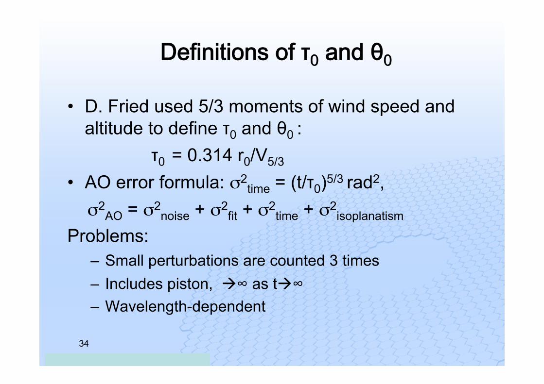
Definitions of τ0 and θ0
• D. Fried used 5/3 moments of wind speed and altitude to define τ0 and θ0 :
τ0 = 0.314 r0/V5/3
• AO error formula: σ2time = (t/τ0)5/3 rad2,
σ2AO = σ2
noise + σ2fit + σ2
time + σ2isoplanatism
Problems: – Small perturbations are counted 3 times – Includes piston, à∞ as tà∞ – Wavelength-dependent
ESO education and Public Outreach | 26.11.2008
35
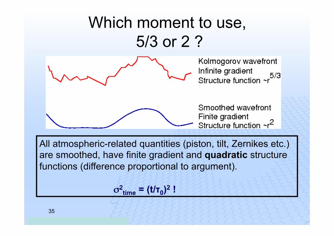
Which moment to use, 5/3 or 2 ?
All atmospheric-related quantities (piston, tilt, Zernikes etc.) are smoothed, have finite gradient and quadratic structure functions (difference proportional to argument). σ2
time = (t/τ0)2 !
ESO education and Public Outreach | 26.11.2008
36
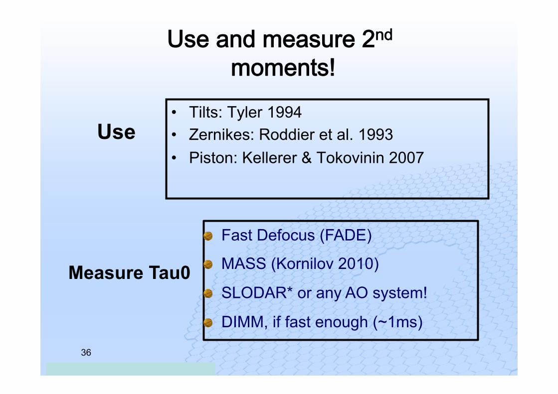
Use and measure 2nd moments!
• Tilts: Tyler 1994 • Zernikes: Roddier et al. 1993 • Piston: Kellerer & Tokovinin 2007
" Fast Defocus (FADE)
" MASS (Kornilov 2010)
" SLODAR* or any AO system!
" DIMM, if fast enough (~1ms)
Use
Measure Tau0
ESO education and Public Outreach | 26.11.2008
37
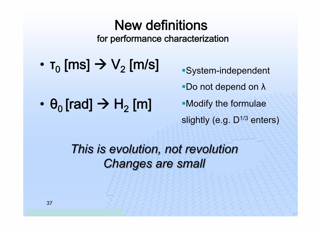
New definitions for performance characterization
• τ0 [ms] à V2 [m/s] • θ0 [rad] à H2 [m]
This is evolution, not revolution Changes are small
§ System-independent
§ Do not depend on λ
§ Modify the formulae
slightly (e.g. D1/3 enters)
ESO education and Public Outreach | 26.11.2008
38
Conclusions
• The existing site monitoring instrument suite fulfills most current AO requirements. Non-common line of sight errors must be quantified.
• The vertical profile of the wind speed should be made available
• The seeing at the telescope should be measured more accurately.
• The AO instruments should produce reliable estimates of atmospheric constants during operation.