Embed Size (px)
Citation preview

Standard Actual
TTest Report
www.vatsmeter.com
Product
Model
Sr. No.
Line Size:
This is to certify that the products mentioned above have been tested and calibrated at our works and have been found working satisfactorily as per the technical specifications of the product.
WARANTY CERTIFICATE We certify that the instrument mentioned above has been tested by us and is guaranteed for a period of 12 months from the date of dispatch. We undertake to make good by replacement or repair defects arising due to faulty design, material and or workmanship within the above mentioned period. Provided that the part in respect to which the complaint is made, is sent at the purchaser`s expense.
The warrantee is valid subject to :
Panel Mounted J-210
FieldMounted A-210
The meter or part there of not being subjecty to alteration, accident abuse or misuse. The installation having been done as per guide lines in the manual.
FLUI D MON I TOR
Client: Rate Indicator + Totalizer + Controller
Date of Dispatch For Vatturkar Industrial
OPEEERRAATTIIOONN MMAANNUUAALL
Serving the Industry since 1993 16

3 2
Dear Customer, Thanks & congratulations on your purchase of the VATS product. For the care & maintenance of your product, pl. go through the precautions. We wish you a long & trouble free life of our product.
Index A. Sensor Details and Installation
1. Sensor Introduction 2. Technical Specifications 3. Material of Construction 4. Wiring
A. Sensor Details and Application Sensor Introduction
VATS Flow Sensor is a paddle wheel insertion type flow sensor, in a robust & compact housing. The sensor makes use of the Faraday’s law of electromagnetic induction. It generates a frequency & signal proportional to the flow. The suspended particles or solid content in the liquid should not be more than 1%. The sensor gives excellent, reliable results in the flow velocity range of 1m/sec to 5 m/sec & for the flow with Reynolds no. greater than 5000. We have Economic JT-121, also Introduced Non Magnetic Sensor JT-122, and High Temp. JT-123 Sensor which is Flameproof..
Technical Specifications 5. Installation Guidelines
B. Electronic monitors 1.Technical Specification 2.Wiring Details 3.Getting started 4.Programming 5.Site Calibration 6.Trouble Shooting
Precautions: STOP! read this carefully before you proceed
Before use of the product, please check for Chemical compatibility, temperature, Pressure parameters of the liquid. Before installation or removal of the sensor depressurize & vent the system. Sensor Cap to be tightened only with hands, do not use any tools. Follow safety measures - Use Helmet, gloves, goggles during installation Please do not alter product construction VATS sensors may not work properly for downstream liquid flow from a certain height because of gravity.
Velocity range Accuracy Input Voltage Output Voltage
Cable length Protecting Rating Operating Temp.
Operating Pressure
: 1 m/sec to 5 m/sec. : +/- 2% of full scale deflection : 12 To 12 V DC : Square wave (Sinking) of 12-24V Open coil o/p amplitude, 15 - 17.5 Hz/meter/second : 0.5 meters for field type, 5 m for panel type : IP-65 : with P.P. Sensor upto 50OC with SS Sensor–upto 70OC/ For JT-123-Upto100OC : upto 5Kg, for Plastic body
0 to 20 Kg for metal body.
Material of Construction (MOC)
Sensor Body Paddle Pin O ring
JT-121 PP PVDF T.C Silicon
Gasket-PTFE
JT-122 SS 316
SS 316
T.C
Gasket-PTFE
JT-123
SS 316
SS 316
T.C
Gasket-PTFE

4 5
Pipe Size (NB) 15 25 40 50 65 80 3
Min Flow M / Hr 0.2 0.8 1.9 3.5 5.8 7.5 3
Max Flow M / Hr 2.1 8.0 19 35 58 75 Pipe Size (NB) 100 125 150 200 250 300
3 Min Flow M / Hr 14 22 31 56 87 126
3 Max Flow M / Hr 140 220 310 560 870 1260
Wiring Installation (contd.)
Red
Shield
Black
12-24 VDC
Common(GND)
Output
}I/P DCV
}O/P Pulse
Inlet Outlet
Flange
10x ID 5x ID
Inlet Reducer
15x ID
Outlet
5x ID
Inlet Outlet
900 Elbow
20x ID 5x ID
*All VATS sensors have Reverse Polarity Protection. *To extend sensor cable, use 2 Core Teflon cable 24/19/36 (silver coated).
Inlet
2x 900 Elbow
2x 900 Elbow
Outlet 3 Dimensions Outlet
Inlet Outlet
Pump / Valve
Installation Guidelines
25x ID 5x ID 40x ID 5x ID 50x ID 5x ID
1. Line Size Selection Chart
Fig. 2 Straight run guidelines in various conditions
B. Sensor Mounting Positions
In Horizontal pipes with sediment-free fluids, the best position is at 90O
To get the exact output from the sensor, minimum flow velocity will be required is 0.2m/s. And for best results Reynolds number(R) is greater than 5000 especially for high viscous liquids. To calculate R use following formula:
45O 45O
If sediment is present the sensor can be mounted at an angle of +/- 45O for better performance.
In vertical pipes, the mounting position can be freely chosen.
3. Actual Installation
2. Placement of the fitting A. Straight Run Requirement
D = Pipe inner diameter in m. F = Flow Rate in LPM. Vis = Kinematic Viscosity in m2 / s.
(Dynamic viscosity / density).
The sensor/indicator can be mounted in vertical as well as horizontal piping
Depressurize the line, remove the blind plug and insert the flow sensor gently.
Ensure that the sensor O-rings are in place and slightly greased and push the sensor in till the threaded cap touches the T fitting. Before tightening the cap ensure that direction of the sensor is proper & the locating pins lock in the notches provided. Do not use tools to tighten the cap. Ensure that the arrow on the sensor point in the direction of flow.
Because of the obstructions like T, Bend, reducer etc. the flow pattern varies a lot. In Fluid Dynamics - it’s called turbulence. In turbulent flow it’s not possible to get precise reading. To nullify the turbulence - the only method is to have a straight run.
In case of field mounted units the sensor must be mounted such that the display becomes parallel to the pipe line. If you are using a weldon adaptor, make sure that the grooves on the threads, where you fit the cap - is parallel to the pipeline.

6 7
B. Electronic Monitors All VATS electronic flow monitors are high speed micro- controller based units with a high resolution back-lit display. By using front panel tactile keys, one can view / program different parameters. It is very important to read the manual before installation to make better use of VATS Flow Meters with full efficiency. A-210 / J-210 is a Digital Rate Indicator suitable for VATS JT-121 sensor or others giving pulse output of 200 Hz max. A-210 / J-210 one can read the flow rate in LPH, M3 / Hr only and corresponding Total reading in Litre or M3 only. Along with these two consecutive displays these monitors also have relays to operate in various modes such as:
A. Batcher B. Pulser C. Rate Switch
Precautions: STOP! read this carefully ! Ensure proper connection of mains, wrong connection may spoil the meter. While extending the cable, use recommended type only, with proper insulation. Avoid noise interference. Do not pass the sensor wire parallel to power cable. If this is unavoidable - pass the sensor cable through noise protected tray.
Getting Started
Technical Specifications Before programming understand the keys.
Key2 is for scrolling the numbers from 0 to 9
Power Supply Function Input Accuracy Meter Size
Display
230 VAC, +/- 10%, 50Hz Rate Indication + Totalizer + Relay output From Vats Sensor JT-121 +/- 2% of full scale A-210 Dia.105 mm x 120 mm deep. J-210:- 72mm x 72mm x 110mm Alphanumeric LCD with backlit 7 digit for Total
Key1 is used to enter program (code 11) and move the cursor left to right
Key1
Key2 Key3 Key3 is the ENTER key,
it’s used to confirm & go to next step.
Protection
and 4 digit for flow rate. IP-65 Programming - View Mode
Wiring - The backside of meter
A-210
J-210
In all Vats Flow Monitors with j ust the press of key2 momentarily one can see all the parameters which are preprogrammed one after the other.
In this mode one can not make any change. It is just to view what is programmed in advance for one second only.
Sensor SENSOR NC
VCC CNT GND
wire goes here
Relay O/P 1 2 3 4 5 6
R B SH
Mains NC wire goes
R - Red wire
7 8 9
10 11 12
Key2
here B - Black wire L N E P NO NC SH - Shield
NC - No Connection 230 V AC RELAY O/P The sequence of different parameters changes as per the desired mode.

9 8
Parameter Batcher Pulser Rate Switch Totalizer Program Code
Scale Scale � � � � 0000031
Exponent Factor � � � � 0000031 Set Relay � � � � 0000011 Hysteresis � � � � 0000011 Batch Counter � � � � 0000011 Reset Batch
counter � � � � 0000011
Reset Total � � � � 0000012 Auto/Manual
Reset � � � � 0000012 Display
Total / batch � � � � 0000012
Programming - View Mode (contd.) Code no. 0310364 Totaliser + (Batcher / Pulser / Rate switch)
SCALE 0.100000
EXPONENT
10 e+0
It indicates the amount of liquid equal to one pulse generated by the sensor. This function is present in all modes. Format is 0.abcdef
It indicates the scale factor is setted in what engineering unit from ml to M3. This function is present in all modes.
This code no. is valid only for key 2, To enter this code long press key 2. Vats A/J- 210 Fluid Monitor Operates in Four different functions:
1. Rate Indicator + Totaliser only 2. Rate Indicator + Totaliser + Batcher 3. Rate Indicator + Totaliser + Pulser
MANUAL RESET!
RELAY
000000.0
HYSTERIS 000000.0
TOTAL
000000.0
BAT. CNT. 0000000_
It indicates resetting of batch is set as mannual. We can set it as automatic reset in setting mode. This function is present in only in Batcher mode.
It indicates relay setting. In Batcher / Pulser mode relay set point in terms of quantity of liquid. In rate switch mode relay set point in terms of Flow rate.
In case of Batcher, hysteris equal to process error. In case of rate switch this is a percentage(%) deviation to be programmed to protect relay from chattering.
It indicates the total quantity of liquid is passed.
It indicates no. of batches taken in Batcher and Pulser mode.
OPER. AS TOTALIZER
OPER. AS BATCHER
OPER. AS PULSER
OPER. AS RATE SW.
It is basic mode in which we can see the flow rate as well as total at the same time on the dual line display
Batcher mode is a popular mode in chemical industries, to get a batch of large quantity consistently. Reset can be manual or automatic. It also displays flow rate as well as total.
It is a small amount repeatative batcher most useful for dosing application. In this mode unit gives short pulses to dosing / metering pupm repeatatively. It also displays flow rate as well as total.
It is another important mode widely used in cooling tower and process industries where flow rate plays an vital role. It gives an tantalizer relay output on the basis of flow rate. Here relay will switch ON at set value and above.
DISPLAY BATCH?
VATS -------
It indicates in Batcher / Pulser mode user setting is to indicate batch inspite of total.
After showing all above parameters the display shows VATS & returns to the main display
Following is the chart which summarizes different parameters available in different modes & the relevant programming codes.
Programming - Enter The Code
Vats advance flow meters are micocontroller based unit . User friendly units provide site calibration and settings of different functions.
To enter the setting mode Vats have provided code no. Entry; so that only concerned person can change the parameters. Different code nos. For different parameters are provided.

11 10
Code no. 00000011 set relay + Hysteris + reset Batch Counter
Code no. 00000012 Auto/Mannual Reset +Display Batch/Total + Reset total
This code no. is valid only for key no. 1. To Enter the this code, press key no. 1 momentarily. After that we enter in relay setting mode. This is not applicable in totalizer mode.
In Batcher mode, we can set relay for desired batch quantity At which the relay will be ON and stop the batching.
MANUAL RESET?
DISPLAY
AUTO
RESET?
DISPLAY
This code no. is valid only for key 2, To enter this code long press key 2
Only in Batcher mode, this function is used to set batcher manual/auto reset.
SETRELAY 000000.0
SET-HYST
In Pulser mode, we can set the relay in such way that it gives pulse to dosing / metering pump after every quantity of liquid was set. In Rate switch mode, relay can set for desired flow rate at which relay will be ON.
In Batcher mode, hysteresis is nothing but process error & is calculated as, Hysteresis = Set quantity - Obtained quantity In Pulser mode, ignore this parameter.
TOTAL?
RESET TOTAL?
BATCH?
TOTAL CLEARED
Only in Batcher mode, this function is used to set meter display to view only total quantity / batch quantity Of liquid.
In all modes, this function is used to reset earlier totalized reading.
000000.0 In rate switch mode, hysteresis is counted in terms of percentage and used to protect relay from chattering. (when the flow rate is fluctuating between set value & nearby value)
VATS --------- After the last parameter, unit returns to main
Code no. 00000031
BAT. CNT. 000000.0
In Batcher & Pulser mode it displays no. of batches taken. This is the number of counts the relay turned ON. To reset batch counter press any key.
set / change scale factor (Site Calibration)
RESET BAT. CNT.
This step asks to reset batch counter. To reset press key1, otherwise press other any key.
SETSCALE 0.000000
EXPONENT 10 e+0
In case of total / batcher recalibration. This is done by changing the scale factor. This is nothing but site calibration. e.g. - Batch is set say 100 lit and by physical measurement the quantity is not matching to the displayed one then one needs to recalibrate as follows by the simple formula below.
VATS ---------
After last parameter, unit go backs to main display. New =
scale Factor MEASU R ED Qty./Fl o w ra te DISPLAYED Qty./ Flowrate
x Old scale factor
NOTE :- In above procedure if user does not make any change within 10 sec. the unit will automatically go back to main display.
After making any change , do not forget to press ENT key. Please check all parameters that you have changed in View mode for confirmation.
By doing this - one will get exact reading. If there is error in set and display due to hysteresis. i.e. Process time to finally stop the flow. Then adjust hysteresis as per page 10 - code 11
Important: The product comes to you pre-calibrated, Do not alter Scale factor without proper technical knowledge. This may result in unreliable readings.
That finishes the preliminary installation guidelines & tips towards proper care & maintenance your flow meter. If you face any problems during & after installation, refer to the trouble-shooting section of this manual.
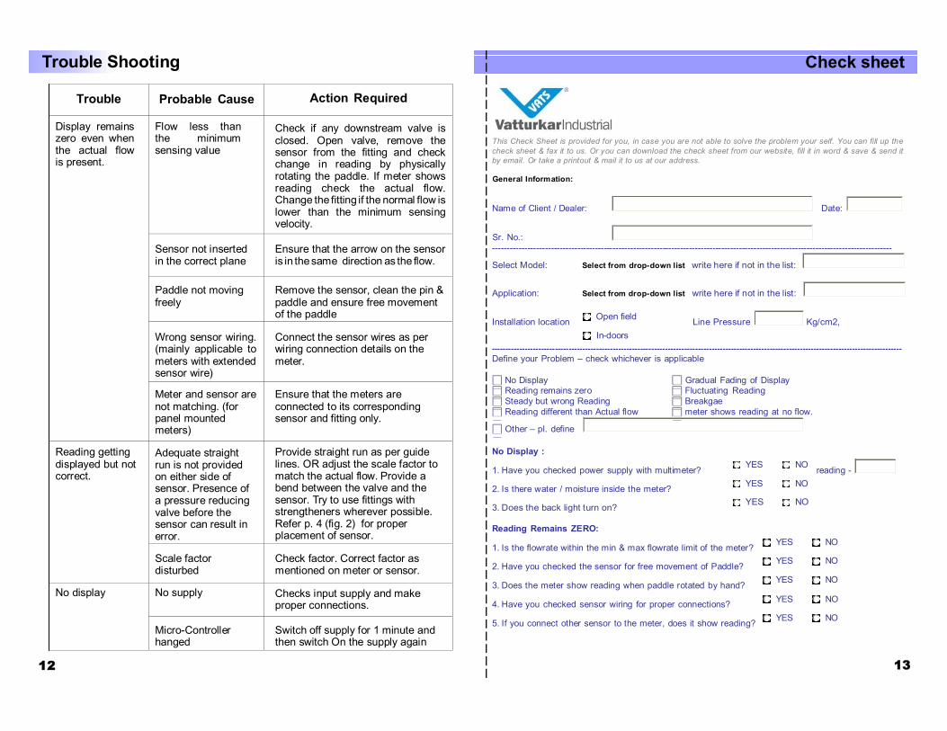
Trouble Probable Cause Action Required
Display remains zero even when the actual flow is present.
Flow less than the minimum sensing value
Check if any downstream valve is closed. Open valve, remove the sensor from the fitting and check change in reading by physically rotating the paddle. If meter shows reading check the actual flow. Change the fitting if the normal flow is lower than the minimum sensing velocity.
Sensor not inserted in the correct plane
Ensure that the arrow on the sensor is in the same direction as the flow.
Paddle not moving freely
Remove the sensor, clean the pin & paddle and ensure free movement of the paddle
Wrong sensor wiring. (mainly applicable to meters with extended sensor wire)
Connect the sensor wires as per wiring connection details on the meter.
Meter and sensor are not matching. (for panel mounted meters)
Ensure that the meters are connected to its corresponding sensor and fitting only.
Reading getting displayed but not correct.
Adequate straight run is not provided on either side of sensor. Presence of a pressure reducing valve before the sensor can result in error.
Provide straight run as per guide lines. OR adjust the scale factor to match the actual flow. Provide a bend between the valve and the sensor. Try to use fittings with strengtheners wherever possible. Refer p. 4 (fig. 2) for proper placement of sensor.
Scale factor disturbed
Check factor. Correct factor as mentioned on meter or sensor.
No display No supply Checks input supply and make proper connections.
Micro-Controller hanged
Switch off supply for 1 minute and then switch On the supply again
Trouble Shooting Check sheet
This Check Sheet is provided for you, in case you are not able to solve the problem your self. You can fill up the check sheet & fax it to us. Or you can download the check sheet from our website, fill it in word & save & send it by email. Or take a printout & mail it to us at our address.
General Information:
Name of Client / Dealer: Date:
Sr. No.: ----------------------------------------------------------------------------------------------------------------------------------------
Select Model: Select from drop-down list write here if not in the list:
Application: Select from drop-down list write here if not in the list:
Installation location Open field Line Pressure Kg/cm2, In-doors
----------------------------------------------------------------------------------------------------------------------------------------------------- Define your Problem – check whichever is applicable
No Display Gradual Fading of Display Reading remains zero Fluctuating Reading Steady but wrong Reading Breakgae Reading different than Actual flow meter shows reading at no flow.
Other – pl. define
No Display :
1. Have you checked power supply with multimeter? YES NO reading -
2. Is there water / moisture inside the meter? YES NO
3. Does the back light turn on? YES NO
Reading Remains ZERO:
1. Is the flowrate within the min & max flowrate limit of the meter? YES NO
2. Have you checked the sensor for free movement of Paddle? YES NO
3. Does the meter show reading when paddle rotated by hand? YES NO
4. Have you checked sensor wiring for proper connections? YES NO
5. If you connect other sensor to the meter, does it show reading? YES NO 12 13

Check sheet Fluctuating reading:
1. Is the sensor located just after any valve/reducer? YES NO
2. Have you checked the sensor for free movement of Paddle? YES NO
3. Are there any air bubbles in the line YES NO
4. Have you checked sensor wiring for proper connections? YES NO
5. Is the sensor wiring extended? YES NO Is there shorting in wires? YES NO
Notes
Steady but wrong reading:
1. Mention the actual flowrate ; Mention the Displayed flowrate
2. The Serial no of Sensor, Meter & Fitting are matching - YES NO
3. Line size mentioned on the indicator same as the fitting - YES NO
4. Scale factor of the meter same as that mentioned on the sticker YES NO
5. Is There is an adequate straight run for the inlet/ outlet - YES NO
6. If straight run is inadequate – Did you adjust scale factor? - YES NO
7. After adjusting the scale factor Is the reading found OK? - YES NO
Breakage: Specify the components broken & likely cause for the same.
Gradual fading of display:
Is the unit is exposed to direct sunlight? YES NO
Meter shows reading even at no flow:
1. Is there an induction motor/coil very close to meter/sensor YES NO
2. Is the extra sensor cable kept looped near to sensor? YES NO
3. Is the plant piping properly grounded? YES NO
4. If the sensor removed from the fitting, reading becomes zero YES NO
5. If sensor wire disconnected from meter reading becomes zero YES NO
Any Other Comments / your Feedback / Suggestions:
Check Sheet filled by:
Company Name 14 15