Embed Size (px)
Citation preview
8/20/2019 Monitor adec monitot
http://slidepdf.com/reader/full/monitor-adec-monitot 1/14
5-26
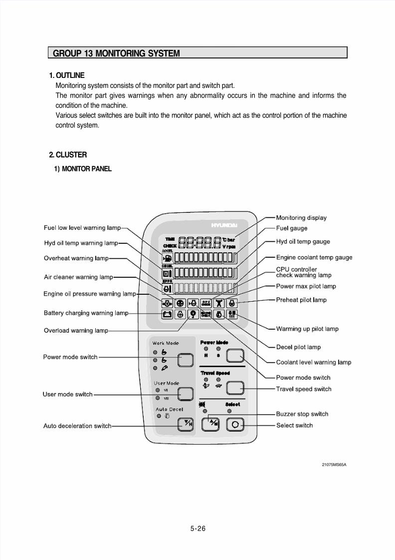
GROUP 13 MONITORING SYSTEM
1. OUTLINE
Monitoring system consists of the monitor part and switch part.
The monitor part gives warnings when any abnormality occurs in the machine and informs thecondition of the machine.
Various select switches are built into the monitor panel, which act as the control portion of the machine
control system.
2. CLUSTER
MONITOR PANEL1)
21075MS65A
8/20/2019 Monitor adec monitot
http://slidepdf.com/reader/full/monitor-adec-monitot 2/14
5-27
CLUSTER CHECK PROCEDURE
Start key : ON
Check monitor initial 5 seconds
All lamps light up.
Buzzer sound.
Check monitor after 5 seconds : Indicate cluster version and machine condition
Cluster program version : CL : 1.4 Indicates program version 1.4 for 2 seconds.
Tachometer : 0rpm
Fuel gauge : All light up below appropriate level
Hydraulic temperature : All light up below appropriate level
Engine coolant temperature gauge : All light up below appropriate level
Warning lamp
During start key ON the engine oil pressure lamp and battery charging lamp go on, but it is not
abnormal.
When engine coolant temperature below 30¡£C, the warming up lamp lights up.
Indicating lamp state
Work mode selection : General work
Power mode selection : S mode
User mode selection : No LED ON
Auto decel LED : ON
Travel speed pilot lamp : Low(Turttle)
Start of engine
Check machine condition
Tachometer indicates at present rpm
Gauge and warning lamp : Indicate at present condition.
When normal condition : All warning lamp OFF
Work mode selection : General work
Power mode selection : S mode
User mode selection : No LED ON
Auto decel LED : ON
Travel speed pilot lamp : Low(Turttle)
When warming up operation
Warming up lamp : ON
10 seconds after engine started, engine speed increases to1200rpm(Auto decel LED : ON)
Others same as above ç̈ .
When abnormal condition
The lamp lights up and the buzzer sounds.
If BUZZER STOP switch is pressed, buzzer sound is canceled but the lamp light up until normal
condition.
2)
(1)
ç̈
è̈
a.
b.
a.
b.
c.
d.
e.
f.
¡Ø
¡Ø
(2)
é̈
ç̈
è̈
é̈
a.
b.
¡Ø
c.
d.
e.
f.
g.
a.
b.
¡Ø
a.
b.
a.
b.
c.
d.
e.
8/20/2019 Monitor adec monitot
http://slidepdf.com/reader/full/monitor-adec-monitot 3/14
5-28
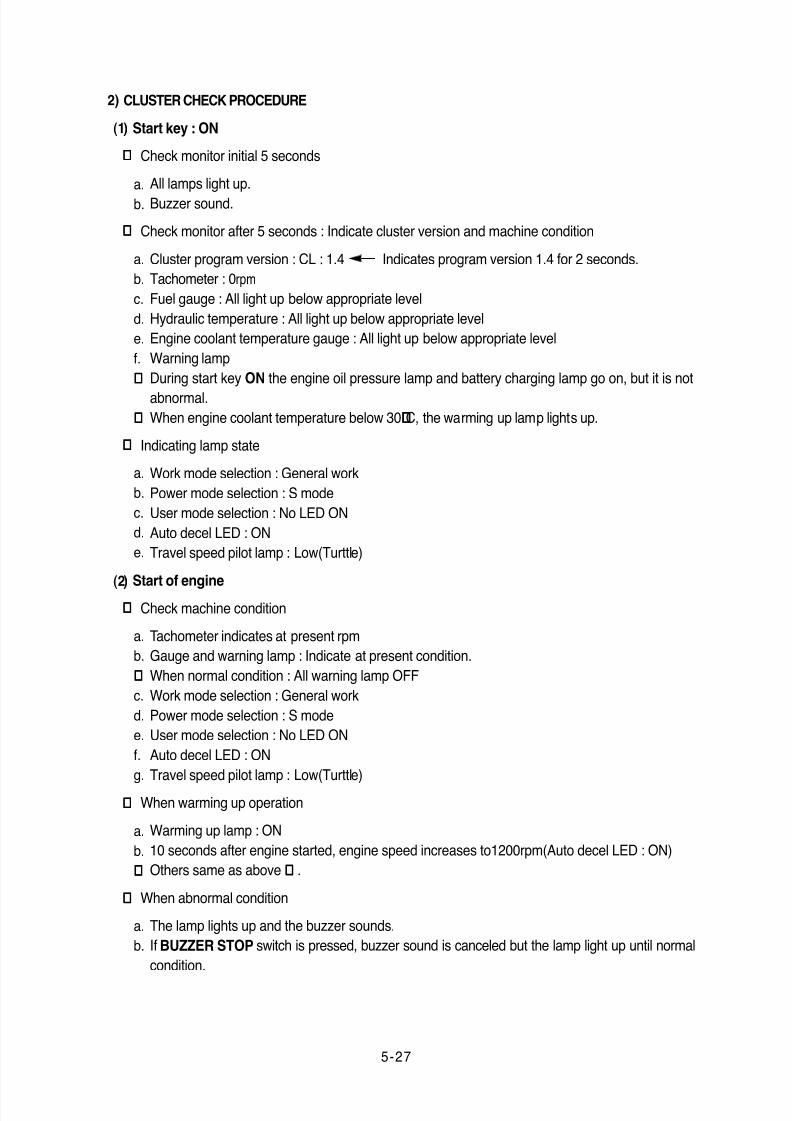
3. CLUSTER CONNECTOR
No. Signal
Cluster
Input / Output
1
2
3
4
Power IG(24V)
GND
Serial-(RX)
Serial+(TX)
Input(20~32V)
Input(0V)
Input(Vpp=12V)
Output(Vpp=4V)
21075MS16
8/20/2019 Monitor adec monitot
http://slidepdf.com/reader/full/monitor-adec-monitot 4/14
5-29
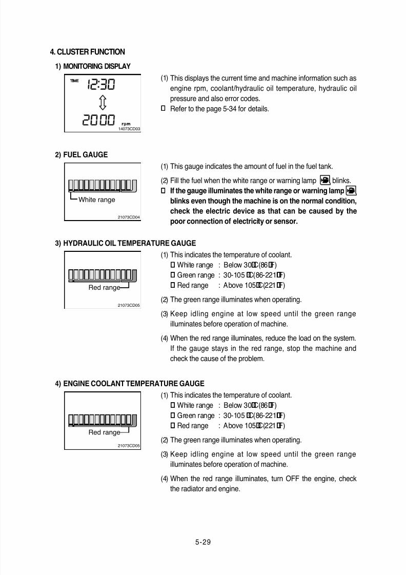
This displays the current time and machine information such as
engine rpm, coolant/hydraulic oil temperature, hydraulic oil
pressure and also error codes.Refer to the page 5-34 for details.
(1)
¡Ø
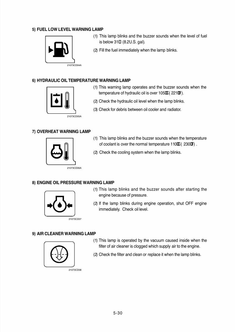
This gauge indicates the amount of fuel in the fuel tank.
Fill the fuel when the white range or warning lamp blinks.
If the gauge illuminates the white range or warning lamp
blinks even though the machine is on the normal condition,check the electric device as that can be caused by the
poor connection of electricity or sensor.
White range
FUEL GAUGE
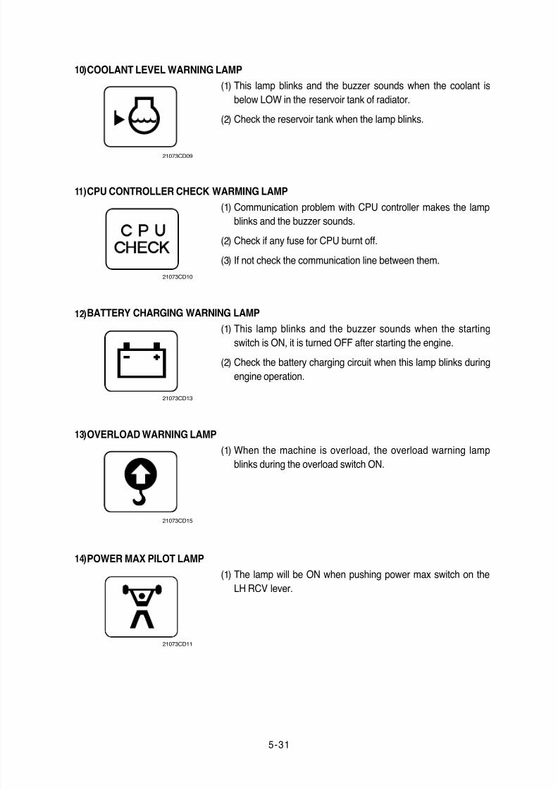
This indicates the temperature of coolant.
¡¤ White range : Below 30¡£C(86¡£F)
¡¤ Green range : 30-105 ¡£C(86-221¡£F)
¡¤ Red range : Above 105¡£C(221¡£F)
The green range illuminates when operating.Keep idling engine at low speed until the green range
illuminates before operation of machine.
When the red range illuminates, reduce the load on the system.
If the gauge stays in the red range, stop the machine and
check the cause of the problem.
Red range
HYDRAULIC OIL TEMPERATURE GAUGE
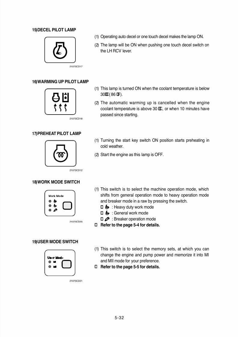
Red range
ENGINE COOLANT TEMPERATURE GAUGE
(1)
(2)
¡Ø
(1)
(2)(3)
(4)
This indicates the temperature of coolant.
¡¤ White range : Below 30¡£C(86¡£F)
¡¤ Green range : 30-105 ¡£C(86-221¡£F)
¡¤ Red range : Above 105¡£C(221¡£F)
The green range illuminates when operating.
Keep idling engine at low speed until the green range
illuminates before operation of machine.
When the red range illuminates, turn OFF the engine, check
the radiator and engine.
(1)
(2)
(3)
(4)
21073CD04
21073CD05
21073CD05
2)
3)
4)
4. CLUSTER FUNCTION
MONITORING DISPLAY1)
14073CD03
8/20/2019 Monitor adec monitot
http://slidepdf.com/reader/full/monitor-adec-monitot 5/14
5-30
This lamp blinks and the buzzer sounds when the level of fuel
is below 31§¤ (8.2U.S. gal).
Fill the fuel immediately when the lamp blinks.
FUEL LOW LEVEL WARNING LAMP
(1)
(2)
5)
This lamp blinks and the buzzer sounds when the temperature
of coolant is over the normal temperature 110¡£C( 230¡£F) .
Check the cooling system when the lamp blinks.
HYDRAULIC OIL TEMPERATURE WARNING LAMP
(1)
(2)
6)
This warning lamp operates and the buzzer sounds when the
temperature of hydraulic oil is over 105¡£C( 221¡£F).
Check the hydraulic oil level when the lamp blinks.
Check for debris between oil cooler and radiator.
OVERHEAT WARNING LAMP
(1)
(2)
(3)
7)
This lamp blinks and the buzzer sounds after starting the
engine because of pressure.
If the lamp blinks during engine operation, shut OFF engine
immediately. Check oil level.
ENGINE OIL PRESSURE WARNING LAMP
(1)
(2)
8)
This lamp is operated by the vacuum caused inside when the
filter of air cleaner is clogged which supply air to the engine.
Check the filter and clean or replace it when the lamp blinks.
AIR CLEANER WARNING LAMP
(1)
(2)
9)
21073CD04A
21073CD05A
21073CD06A
21073CD07
21073CD08
8/20/2019 Monitor adec monitot
http://slidepdf.com/reader/full/monitor-adec-monitot 6/14
5-31
This lamp blinks and the buzzer sounds when the coolant is
below LOW in the reservoir tank of radiator.
Check the reservoir tank when the lamp blinks.
COOLANT LEVEL WARNING LAMP
(1)
(2)
10)
Communication problem with CPU controller makes the lamp
blinks and the buzzer sounds.
Check if any fuse for CPU burnt off.
If not check the communication line between them.
(1)
(2)
(3)
CPU CONTROLLER CHECK WARMING LAMP11)
This lamp blinks and the buzzer sounds when the starting
switch is ON, it is turned OFF after starting the engine.
Check the battery charging circuit when this lamp blinks during
engine operation.
BATTERY CHARGING WARNING LAMP
(1)
(2)
12)
When the machine is overload, the overload warning lamp
blinks during the overload switch ON.
(1)
OVERLOAD WARNING LAMP13)
The lamp will be ON when pushing power max switch on the
LH RCV lever.
(1)
POWER MAX PILOT LAMP14)
21073CD09
21073CD10
21073CD13
21073CD15
21073CD11
8/20/2019 Monitor adec monitot
http://slidepdf.com/reader/full/monitor-adec-monitot 7/14
5-32
Operating auto decel or one touch decel makes the lamp ON.
The lamp will be ON when pushing one touch decel switch on
the LH RCV lever.
(1)
(2)
DECEL PILOT LAMP15)
This lamp is turned ON when the coolant temperature is below
30¡£C( 86 ¡£F).
The automatic warming up is cancelled when the engine
coolant temperature is above 30 ¡£C, or when 10 minutes have
passed since starting.
WARMING UP PILOT LAMP
(1)
(2)
16)
Turning the start key switch ON position starts preheating in
cold weather.
Start the engine as this lamp is OFF.
PREHEAT PILOT LAMP
(1)
(2)
17)
This switch is to select the machine operation mode, which
shifts from general operation mode to heavy operation mode
and breaker mode in a raw by pressing the switch.
¡¤ : Heavy duty work mode
¡¤ : General work mode
¡¤ : Breaker operation mode
Refer to the page 5-4 for details.
WORK MODE SWITCH
(1)
¡Ø
18)
USER MODE SWITCH19)
This switch is to select the memory sets, at which you can
change the engine and pump power and memorize it into MI
and MII mode for your preference.
Refer to the page 5-5 for details.
(1)
¡Ø
21073CD17
21073CD18
21073CD12
21073CD20
21073CD21
8/20/2019 Monitor adec monitot
http://slidepdf.com/reader/full/monitor-adec-monitot 8/14
5-33
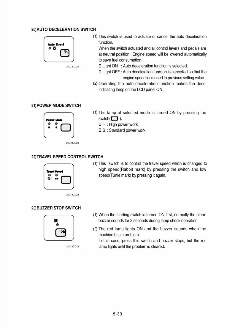
AUTO DECELERATION SWITCH20)
The lamp of selected mode is turned ON by pressing the
switch( ).
¡¤ H : High power work.
¡¤ S : Standard power work.
POWER MODE SWITCH
(1)
21)
This switch is to control the travel speed which is changed to
high speed(Rabbit mark) by pressing the switch and low
speed(Turtle mark) by pressing it again.
TRAVEL SPEED CONTROL SWITCH
(1)
22)
When the starting switch is turned ON first, normally the alarm
buzzer sounds for 2 seconds during lamp check operation.
The red lamp lights ON and the buzzer sounds when the
machine has a problem.
In this case, press this switch and buzzer stops, but the red
lamp lights until the problem is cleared.
BUZZER STOP SWITCH
(1)
(2)
23)
This switch is used to actuate or cancel the auto deceleration
function.
When the switch actuated and all control levers and pedals are
at neutral position. Engine speed will be lowered automatically
to save fuel consumption.
¡¤ Light ON : Auto deceleration function is selected.
¡¤ Light OFF : Auto deceleration function is cancelled so that the
engine speed increased to previous setting value.
Operating the auto deceleration function makes the decel
indicating lamp on the LCD panel ON.
(1)
(2)
21073CD22
21073CD23
21073CD24
21073CD25
8/20/2019 Monitor adec monitot
http://slidepdf.com/reader/full/monitor-adec-monitot 9/14
5-34
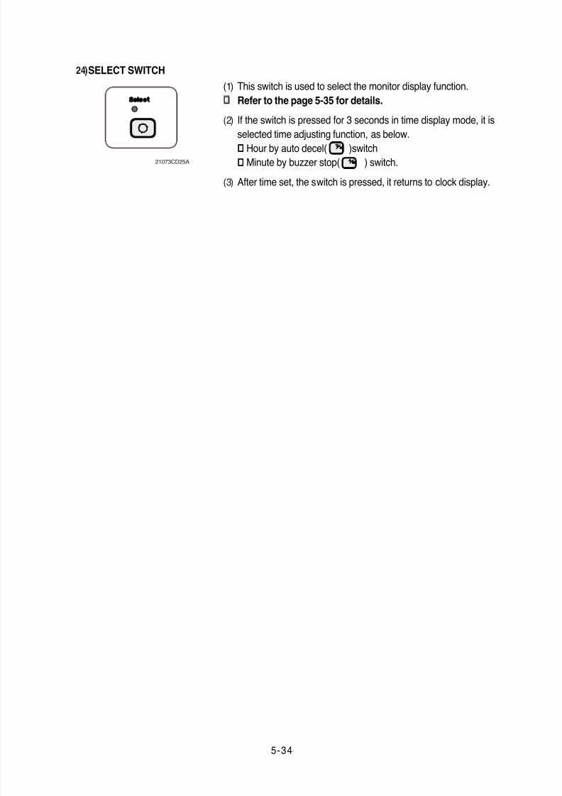
This switch is used to select the monitor display function.
Refer to the page 5-35 for details.
If the switch is pressed for 3 seconds in time display mode, it is
selected time adjusting function, as below.¡¤ Hour by auto decel( )switch
¡¤ Minute by buzzer stop( ) switch.
After time set, the switch is pressed, it returns to clock display.
SELECT SWITCH
(1)
¡Ø
(2)
(3)
24)
21073CD25A
8/20/2019 Monitor adec monitot
http://slidepdf.com/reader/full/monitor-adec-monitot 10/14
5-35
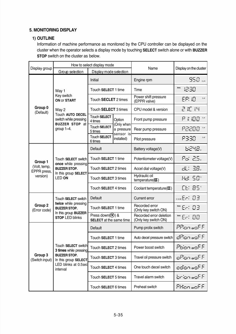
5. MONITORING DISPLAY
OUTLINE
Information of machine performance as monitored by the CPU controller can be displayed on the
cluster when the operator selects a display mode by touching SELECT switch alone or with BUZZER
STOP switch on the cluster as below.
1)
Way 1Key switchON or START
Way 2Touch AUTO DECEL
switch while pressingBUZZER STOP atgroup 1~4.
Group 0(Default)
Group 1(Volt, temp,
EPPR press,
version)
Group 2(Error code)
Touch SELECT switchonce while pressing
BUZZER STOP.
In this group SELECT
LED ON
Touch SELECT switchtwice while pressingBUZZER STOP.
In this group BUZZER
STOP LED blinks
How to select display mode
Group selection Display mode selectionNameDisplay group Display on the cluster
Group 3(Switch input)
Touch SELECT switch3 times while pressingBUZZER STOP.
In this group SELECT
LED blinks at 0.5secinterval
or
or
or
or
or
or
or
Initial
Touch SELECT 1 time
Touch SECLET 2 times
Touch SELECT 3 times
Option(Only whena pressuresensor isinstalled)
Default
Touch SELECT 1 time
Touch SELECT 2 times
Touch SELECT 3 times
Touch SELECT 4 times
Default
Touch SELECT 1 time
Press down( ) &SELECT at the same time
Default
Touch SELECT 1 time
Touch SELECT 2 times
Touch SELECT 3 times
Touch SELECT 4 times
Touch SELECT 5 times
Touch SELECT 6 times
Touch SELECT4 times
Touch SELECT
5 times
Touch SELECT
6 times
Engine rpm
Time
Power shift pressure(EPPR valve)
CPU model & version
Front pump pressure
Rear pump pressure
Pilot pressure
Battery voltage(V)
Potentiometer voltage(V)
Accel dial voltage(V)
Hydraulic oiltemperature(¡£C)
Coolant temperature(¡£C)
Current error
Recorded error(Only key switch ON)
Recorded error deletion(Only key switch ON)
Pump prolix switch
Auto decel pressure switch
Power boost switch
Travel oil pressure switch
One touch decel switch
Travel alarm switch
Preheat switch
8/20/2019 Monitor adec monitot
http://slidepdf.com/reader/full/monitor-adec-monitot 11/14
5-36
or
or
or
or
or
or
or
or
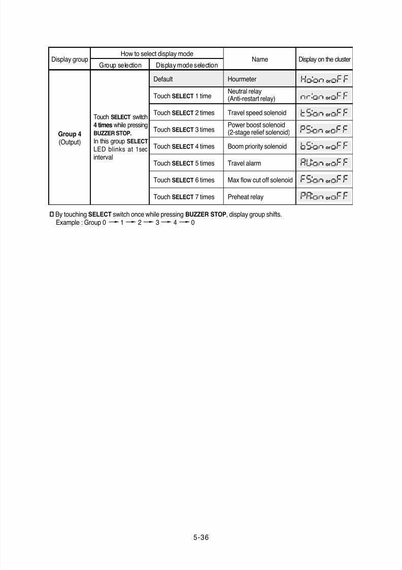
Group 4(Output)
Touch SELECT switch4 times while pressingBUZZER STOP.
In this group SELECT
LED blinks at 1secinterval
How to select display mode
Group selection Display mode selectionNameDisplay group Display on the cluster
Hourmeter
Neutral relay
(Anti-restart relay)
Travel speed solenoid
Power boost solenoid(2-stage relief solenoid)
Boom priority solenoid
Travel alarm
Max flow cut off solenoid
Preheat relay
Default
Touch SELECT 1 time
Touch SELECT 2 times
Touch SELECT 3 times
Touch SELECT 4 times
Touch SELECT 5 times
Touch SELECT 6 times
Touch SELECT 7 times
¡Ø By touching SELECT switch once while pressing BUZZER STOP, display group shifts.Example : Group 0 1 2 3 4 0
8/20/2019 Monitor adec monitot
http://slidepdf.com/reader/full/monitor-adec-monitot 12/14
5-37
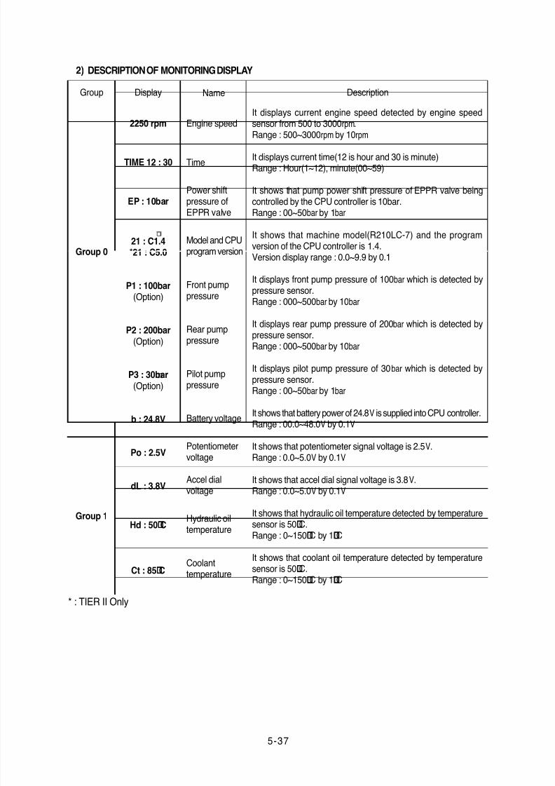
DESCRIPTION OF MONITORING DISPLAY2)
Group Display Name Description
2250 rpm
TIME 12 : 30
EP : 10bar
21 : C1.4*21 : C5.0
P1 : 100bar(Option)
P2 : 200bar(Option)
P3 : 30bar(Option)
b : 24.8V
Po : 2.5V
dL : 3.8V
Hd : 50¡£C
Ct : 85¡£C
It displays current engine speed detected by engine speedsensor from 500 to 3000rpm.
Range : 500~3000rpm by 10rpm
It displays current time(12 is hour and 30 is minute)Range : Hour(1~12), minute(00~59)
It shows that pump power shift pressure of EPPR valve beingcontrolled by the CPU controller is 10bar.Range : 00~50bar by 1bar
It shows that machine model(R210LC-7) and the programversion of the CPU controller is 1.4.Version display range : 0.0~9.9 by 0.1
It displays front pump pressure of 100bar which is detected bypressure sensor.Range : 000~500bar by 10bar
It displays rear pump pressure of 200bar which is detected bypressure sensor.Range : 000~500bar by 10bar
It displays pilot pump pressure of 30bar which is detected bypressure sensor.Range : 00~50bar by 1bar
It shows that battery power of 24.8V is supplied into CPU controller.Range : 00.0~48.0V by 0.1V
It shows that potentiometer signal voltage is 2.5V.Range : 0.0~5.0V by 0.1V
It shows that accel dial signal voltage is 3.8V.Range : 0.0~5.0V by 0.1V
It shows that hydraulic oil temperature detected by temperaturesensor is 50¡£C.Range : 0~150¡£C by 1¡£C
It shows that coolant oil temperature detected by temperaturesensor is 50¡£C.Range : 0~150¡£C by 1¡£C
Engine speed
Time
Power shiftpressure ofEPPR valve
Model and CPUprogram version
Front pumppressure
Rear pumppressure
Pilot pumppressure
Battery voltage
Potentiometervoltage
Accel dialvoltage
Hydraulic oiltemperature
Coolanttemperature
Group 1
Group 0
* : TIER II Only
8/20/2019 Monitor adec monitot
http://slidepdf.com/reader/full/monitor-adec-monitot 13/14
5-38
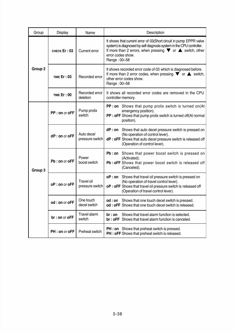
Group Display Name Description
CHECK Er : 03
TIME Er : 03
TIME Er : 00
PP : on or oFF
dP : on or oFF
Pb : on or oFF
oP : on or oFF
od : on or oFF
br : on or oFF
PH : on or oFF
It shows that current error of 03(Short circuit in pump EPPR valvesystem) is diagnosed by self diagnosis system in the CPU controller.If more than 2 errors, when pressing or switch, othererror codes show.Range : 00~58
It shows recorded error code of 03 which is diagnosed before.If more than 2 error codes, when pressing or switch,other error codes show.Range : 00~58
It shows all recorded error codes are removed in the CPUcontroller memory.
Current error
Recorded error
Recorded errordeletion
Pump prolix
switch
Auto decelpressure switch
Powerboost switch
Travel oilpressure switch
One touchdecel switch
Travel alarmswitch
Preheat switch
Group 3
Group 2
Shows that pump prolix switch is turned on(Atemergency position).
Shows that pump prolix switch is turned off(At normalposition).
Shows that auto decel pressure switch is pressed on(No operation of control lever).Shows that auto decel pressure switch is released off(Operation of control lever).
Shows that power boost switch is pressed on(Activated).Shows that power boost switch is released off(Canceled).
Shows that travel oil pressure switch is pressed on(No operation of travel control lever).Shows that travel oil pressure switch is released off(Operation of travel control lever).
Shows that one touch decel switch is pressed.Shows that one touch decel switch is released.
Shows that travel alarm function is selected.Shows that travel alarm function is canceled.
Shows that preheat switch is pressed.
Shows that preheat switch is released.
PP : on
PP : oFF
dP : on
dP : oFF
Pb : on
Pb : oFF
oP : on
oP : oFF
od : onod : oFF
br : onbr : oFF
PH : on
PH : oFF
8/20/2019 Monitor adec monitot
http://slidepdf.com/reader/full/monitor-adec-monitot 14/14
5-39
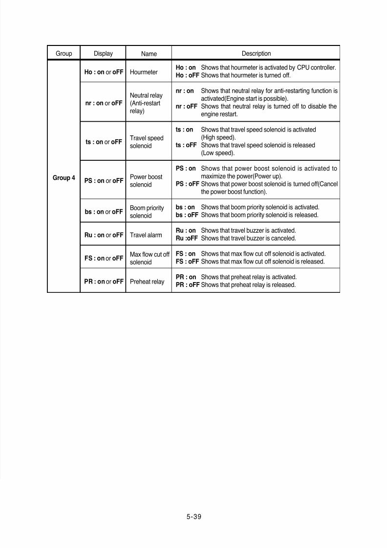
Group Display Name Description
Ho : on or oFF
nr : on or oFF
ts : on or oFF
PS : on or oFF
bs : on or oFF
Ru : on or oFF
FS : on or oFF
PR : on or oFF
Shows that hourmeter is activated by CPU controller.Shows that hourmeter is turned off.
Shows that neutral relay for anti-restarting function isactivated(Engine start is possible).Shows that neutral relay is turned off to disable theengine restart.
Shows that travel speed solenoid is activated(High speed).Shows that travel speed solenoid is released(Low speed).
Shows that power boost solenoid is activated tomaximize the power(Power up).Shows that power boost solenoid is turned off(Cancel
the power boost function).
Shows that boom priority solenoid is activated.Shows that boom priority solenoid is released.
Shows that travel buzzer is activated.Shows that travel buzzer is canceled.
Shows that max flow cut off solenoid is activated.Shows that max flow cut off solenoid is released.
Shows that preheat relay is activated.
Shows that preheat relay is released.
Hourmeter
Neutral relay(Anti-restartrelay)
Travel speedsolenoid
Power boostsolenoid
Boom prioritysolenoid
Travel alarm
Max flow cut offsolenoid
Preheat relay
Group 4
Ho : onHo : oFF
nr : on
nr : oFF
ts : on
ts : oFF
PS : on
PS : oFF
bs : onbs : oFF
Ru : onRu :oFF
FS : onFS : oFF
PR : on
PR : oFF