Embed Size (px)
Citation preview

MONALISA 2.0 - EMSN INFRASTRUCTURAL SPECIFICATION
1
MONALISA 2.0 – Activity 1
EMSN Infrastructural Specification
Document No: MONALISA 2 0_D1.4

MONALISA 2.0 - EMSN INFRASTRUCTURAL SPECIFICATION
2
Approval Signatures Rheinmetall Defence Electronics GmbH Author: Ihmels, Heiko SPM 08.10.2015 Name Dept. Date Signature
Verified by: Grube, Christian SPM 08.10.2015 Name Dept. Date Signature Transas Marine International Reviewer: Lundqvist, Ola SIM Name Dept. Date Signature Swedish Maritime Administration Approved by: Karlsson, Fredrik Name Dept. Date Signature

MONALISA 2.0 - EMSN INFRASTRUCTURAL SPECIFICATION
3
Table of Contents
1 Document Overview .................................................................................................... 8
2 Introduction .................................................................................................................. 9
3 Network Architecture ................................................................................................ 11
3.1Network Topology .................................................................................................... 11
3.2Site Topology ........................................................................................................... 13
3.3Subnets .................................................................................................................... 15
3.4 Internet Access Point ............................................................................................... 17
3.5Network Devices ...................................................................................................... 17
3.6Tools ........................................................................................................................ 17
4 Distributed Interactive Simulation ........................................................................... 18
4.1Protocol Data Units .................................................................................................. 18
4.2Sites & Applications ................................................................................................. 20
4.3DIS Entities .............................................................................................................. 22
5 Voice Communication ............................................................................................... 24
5.1Simulation of VHF channels ..................................................................................... 24
5.2 Intercom between Instructors ................................................................................... 24
5.3System requirements ............................................................................................... 24
5.4Real Handsets .......................................................................................................... 25
6 Exercises .................................................................................................................... 26
7 Further Requirements ............................................................................................... 27
Appendix A: Modelling Automatic Identification System (AIS) on DIS ...................... 28
General ........................................................................................................................... 28
Transmitter PDU ............................................................................................................. 28
Receiver PDU ................................................................................................................. 29
Signal PDU ..................................................................................................................... 30
MONALISA 2.0 - EMSN INFRASTRUCTURAL SPECIFICATION
4
List of Figures Figure 1: VPN topology of the EMSN ................................................................................ 12Figure 2: Topology of VPN sites ........................................................................................ 13Figure 3: Subnets in the EMSN ......................................................................................... 15Figure 4: TeamSpeak settings for using real handset ....................................................... 25
List of Tables Table 1: Subnet addresses ................................................................................................ 16Table 3: Site & application IDs .......................................................................................... 21Table 4: Entity types .......................................................................................................... 23
MONALISA 2.0 - EMSN INFRASTRUCTURAL SPECIFICATION
5
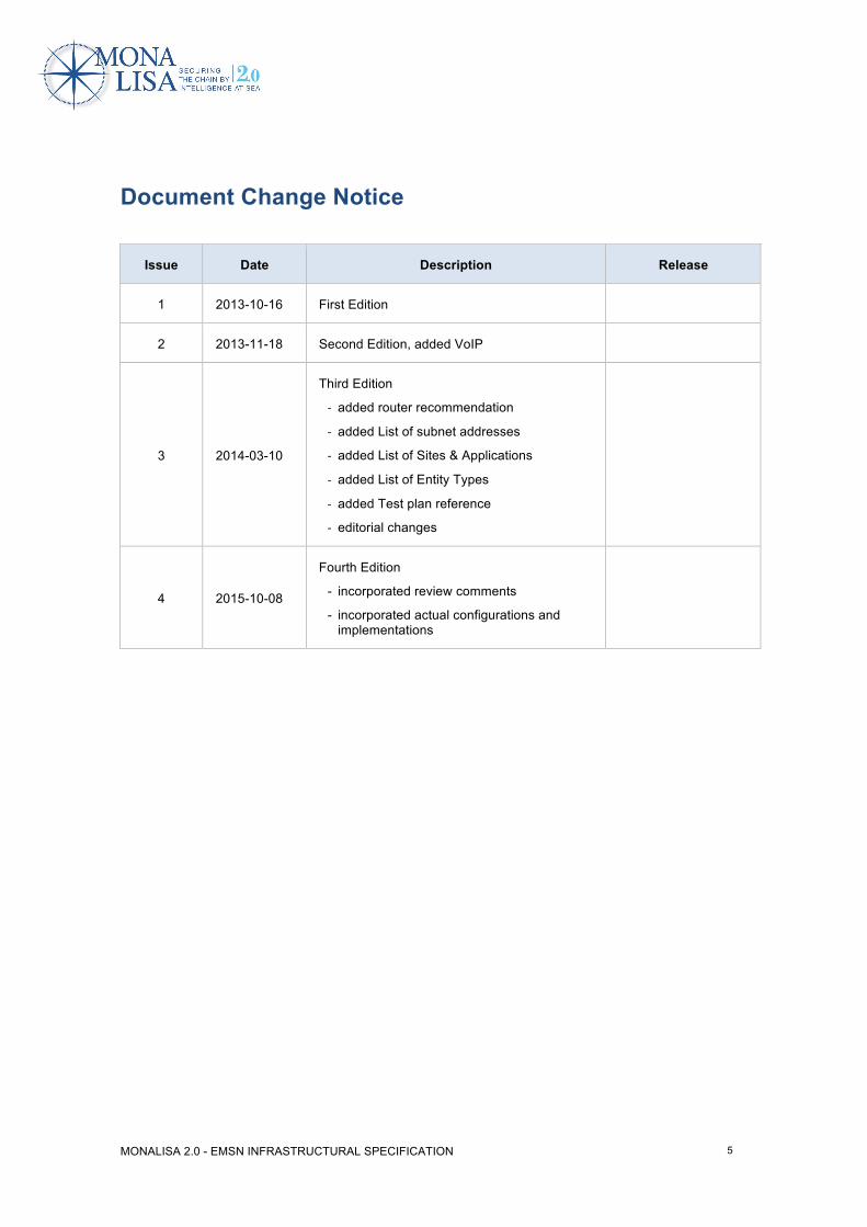
Document Change Notice
Issue Date Description Release
1 2013-10-16 First Edition
2 2013-11-18 Second Edition, added VoIP
3 2014-03-10
Third Edition
- added router recommendation
- added List of subnet addresses
- added List of Sites & Applications
- added List of Entity Types
- added Test plan reference
- editorial changes
4 2015-10-08
Fourth Edition
- incorporated review comments
- incorporated actual configurations and implementations
MONALISA 2.0 - EMSN INFRASTRUCTURAL SPECIFICATION
6
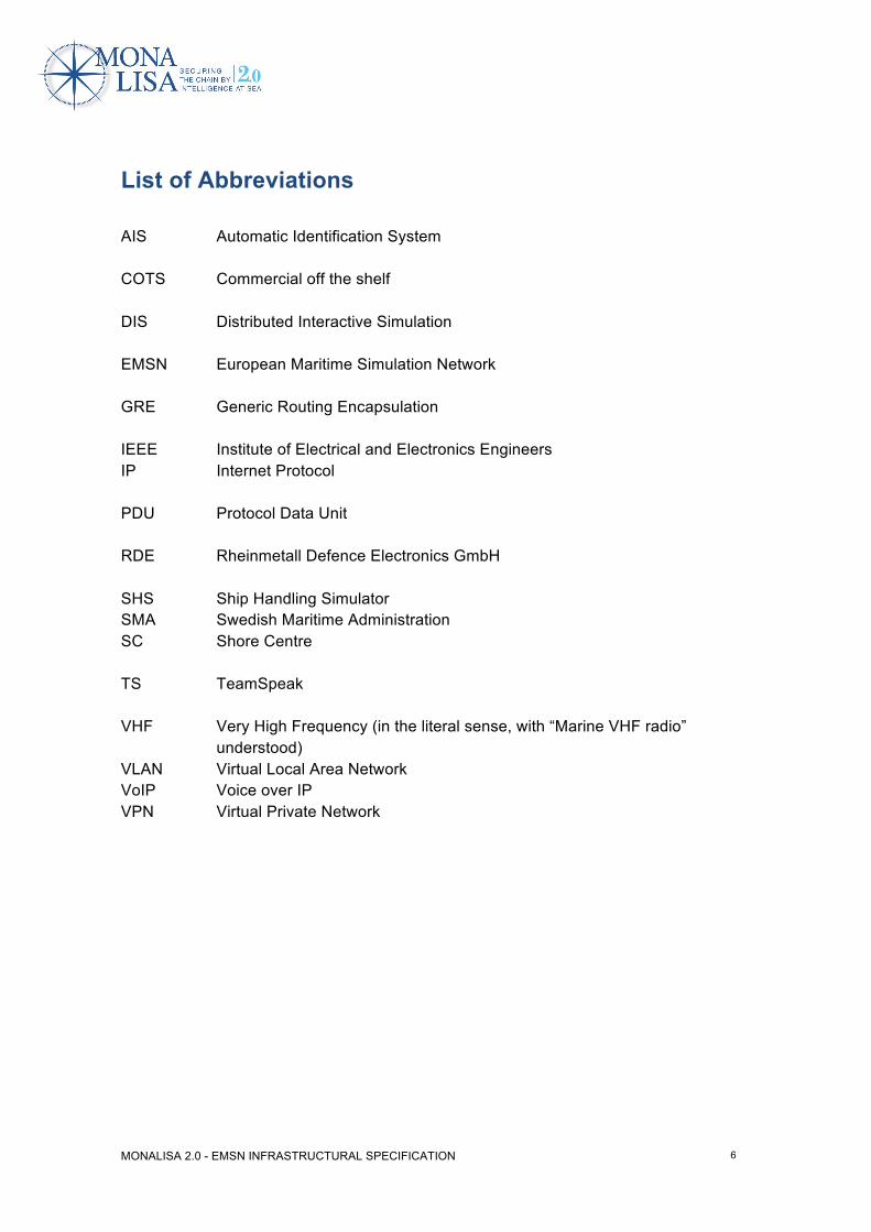
List of Abbreviations AIS Automatic Identification System COTS Commercial off the shelf DIS Distributed Interactive Simulation EMSN European Maritime Simulation Network GRE Generic Routing Encapsulation IEEE Institute of Electrical and Electronics Engineers IP Internet Protocol PDU Protocol Data Unit RDE Rheinmetall Defence Electronics GmbH SHS Ship Handling Simulator SMA Swedish Maritime Administration SC Shore Centre TS TeamSpeak VHF Very High Frequency (in the literal sense, with “Marine VHF radio”
understood) VLAN Virtual Local Area Network VoIP Voice over IP VPN Virtual Private Network

MONALISA 2.0 - EMSN INFRASTRUCTURAL SPECIFICATION
7
List of References Project /MONALISA/ http://monalisaproject.eu/ /TESTPLAN/ MONALISA Test Plan, published on Projectplace-Server:
https://service.projectplace.com/pp/pp.cgi/0/888405764?op=wget#folder/984033408
Standards /AIS/ Technical characteristics for an automatic identification system using
time-division multiple access in the VHF maritime mobile band http://www.itu.int/rec/R-REC-M.1371-3-200706-S/en
/DIS/ IEEE Standard for Distributed Interactive Simulation - Application Protocols IEEE Std 1278.1a-1998
/DIS-ENUM/ Enumerations for Simulation Interoperability SISO-REF-010-2011.1 http://www.sisostds.org/ProductsPublications/ReferenceDocuments.aspx
/NMEA/ NMEA 0183 http://www.nmea.org/content/nmea_standards/nmea_0183_v_410.asp
/VPN/ http://www.vpnc.org/vpn-standards.html Tools /TEAMSPEAK/ http://www.teamspeak.com /WIRESHARK/ http://www.wireshark.org Hardware /ROUTER/ http://www.cisco.com/en/US/products/ps9556/
MONALISA 2.0 - EMSN INFRASTRUCTURAL SPECIFICATION
8
1 Document Overview This document describes the infrastructural specification for the European Maritime Simulation Network (EMSN) which is part of the MONALISA 2.0 project (/MONALISA/). In the chapter “Introduction” a short overview is given about the European Maritime Simulation Network (EMSN) and its architecture. The chapter “Network Architecture” describes the EMSN architecture in detail followed by chapter “Distributed Interactive Simulation” which addresses some aspects of the simulation network that are relevant for the EMSN. The “Voice communication” chapter describes the usage of /TEAMSPEAK/ to simulate VHF communication.

MONALISA 2.0 - EMSN INFRASTRUCTURAL SPECIFICATION
9
2 Introduction Cit. http://monalisaproject.eu/ “The vision is to shake up and sharpen the whole transport chain by making real-time information available to all interested and authorised parties. It is called Sea Traffic Management (STM) and it will change the maritime world. It is like introducing the Smartphone, at first no one really knows what they need it for, and then they cannot live without it, “says Magnus Sundström. He is the project manager, and is building on the success of previous projects. “The short term benefits of MONALISA 2.0 are improved safety, environment and efficiency. Safety is improved by concrete initiatives on board ships, e.g. indoor positioning, and on shore, e.g. mass evacuation in port. We want to give the industry tool in order to avoid incidents and better handle the ones that occur. We believe that mariners, passengers and goods deserve a safer and more efficient journey.”” This specification is made to introduce a technical solution to all participants of the MONALISA 2.0 project, who want to join the European Maritime Simulation Network (EMSN) with their respective simulators. The main goal of this specification is to achieve a technically stable and proven approach, which is easy and cost effective as well as fast to implement. This is vital to the project, since it has a very ambitious timeline that limits additional development of new technologies to provide the needed simulation network. The Distributed Interactive Simulation (DIS) is chosen as the underlying communication protocol to support the simulation data exchange between connected simulators. Key benefits are:
• International standard protocol for simulation networks (IEEE 1278)
• Open standard with no licence costs
• Very simple infrastructural requirements
• Easy to implement (if not available already)
• No need to open up existing proprietary simulator software to others
• Already covers all requirements for MONALISA 2.0
• Supported by a variety of proven COTS tools for maintenance, support and analysis

MONALISA 2.0 - EMSN INFRASTRUCTURAL SPECIFICATION
10
Besides the transport of simulation data the EMSN also has to support voice communication and the distribution of MONALISA 2.0 data. The EMSN is based on public Internet resources protected by the tunnelling mechanism of virtual private networks.
MONALISA 2.0 - EMSN INFRASTRUCTURAL SPECIFICATION
11
3 Network Architecture
3.1 Network Topology The primary purpose of the EMSN is to gain experience with MONALISA’s features and to understand how involved persons and institutions deal with its capabilities. This shall be done in a simulated environment, which saves time, costs and environmental impact. The EMSN consists of one or more Shore Centres (SC) and several ship handling simulators (SHS) spread across European locations. In order to enable a sufficient realistic evaluation of MONALISA’s capabilities a minimum set of services has to be established with the EMSN.
• Distribution of simulated exercise data which consists primarily of published entity data that represent the participating simulated ships.
• Voice communication between SHSs among each other and between them and the SC emulating real world radio communication.
• Supply of network capacity for the MONALISA data communication.
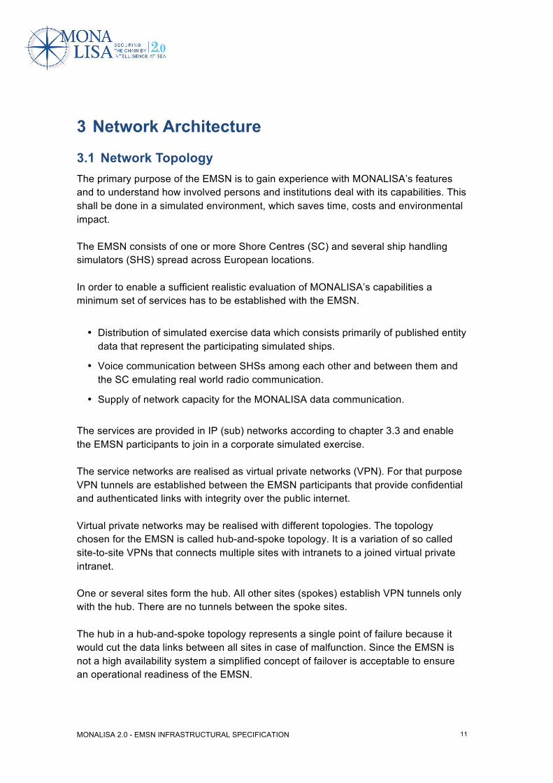
The services are provided in IP (sub) networks according to chapter 3.3 and enable the EMSN participants to join in a corporate simulated exercise. The service networks are realised as virtual private networks (VPN). For that purpose VPN tunnels are established between the EMSN participants that provide confidential and authenticated links with integrity over the public internet. Virtual private networks may be realised with different topologies. The topology chosen for the EMSN is called hub-and-spoke topology. It is a variation of so called site-to-site VPNs that connects multiple sites with intranets to a joined virtual private intranet. One or several sites form the hub. All other sites (spokes) establish VPN tunnels only with the hub. There are no tunnels between the spoke sites. The hub in a hub-and-spoke topology represents a single point of failure because it would cut the data links between all sites in case of malfunction. Since the EMSN is not a high availability system a simplified concept of failover is acceptable to ensure an operational readiness of the EMSN.
MONALISA 2.0 - EMSN INFRASTRUCTURAL SPECIFICATION
12
A failure of the hub shall be compensated by providing a backup hub site that can act as a substitute for the failing hub. It is proposed to locate the main hub at the SMA / Chalmers University and the backup hub at one of the manufacturers, e.g. RDE. Figure 1 illustrates the VPN topology of the EMSN.
Figure 1: VPN topology of the EMSN
Internet
VPN Router VPN Router VPN Router
VPN RouterVPN Router
SHS Site 1 SHS Site N SC Site
Main Hub Site Backup Hub Site
VPN Tunnel
Spokes
Hubs
MONALISA 2.0 - EMSN INFRASTRUCTURAL SPECIFICATION
13
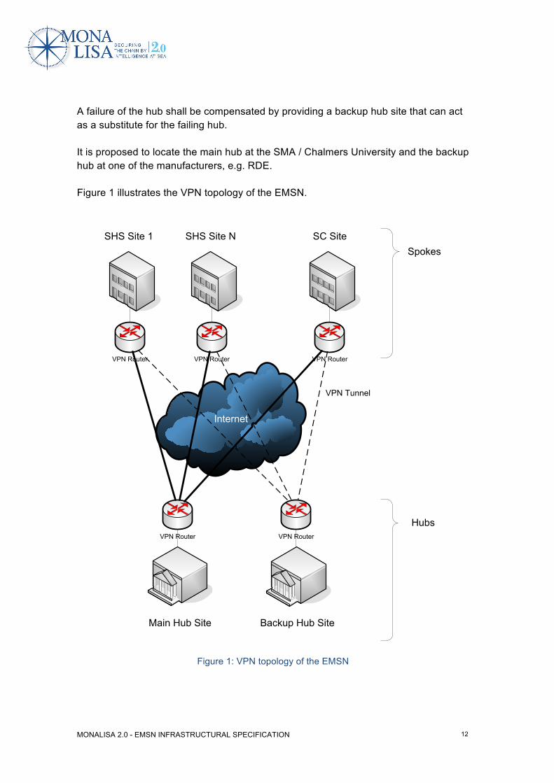
3.2 Site Topology The network topology of each site follows Figure 2. Each site is connected with the internet by a VPN router which establishes the virtual EMSN subnets between hubs and spokes. The service components providing distribution of simulation and voice data are connected with the VPN router. The EMSN was designed for and is capable of handling of MONALISA data as well, but during the progress of the project, it was decided that MONALISA devices and applications are connected directly to the Internet and are not passing data through the EMSN. The following picture was adapted accordingly.
Figure 2: Topology of VPN sites
Internet
VPN Gateway / Router
Simulator / Simulation Management
Voice (TeamSpeak) MONALISADIS Gateway
[TCP][VoIP][UDP Multicast]
[VPN Tunnel]
MONALISA 2.0 - EMSN INFRASTRUCTURAL SPECIFICATION
14
The simulation systems are considered to be manufacturer-specific. Therefore the widespread Distributed Interactive Simulation (DIS) protocol is introduced in order to provide a corporate mechanism for distribution of simulation data and to hide proprietary simulation protocols. If a SHS does not support the DIS protocol an additional DIS gateway has to be installed that transforms proprietary simulation protocols to the DIS protocol and vice versa. It is assumed that it is the task of the simulator manufacturer to provide such a DIS gateway. The DIS PDUs are distributed by UDP multicast. In the context of EMSN each site represents a single multicast domain which means that DIS PDUs are not automatically distributed within the EMSN. To overcome this problem the router devices must support multicast over VPN. Due to the fact that the IPsec protocol used for VPN connections supports unicast IP only generic routing encapsulation (GRE) is used to encapsulate the multicast protocol data. Finally, the data is secured by IPsec in a VPN. The functional chain comprising the simulator and the DIS gateway are present at all sites. At SHS sites it is used to exchange simulated ship data with other sites. Furthermore, one of the sites has to take the simulation manager role. An obvious candidate for that could be the main hub. Voice is distributed by voice over IP (VoIP). This is a well-known use case for VPNs so this does not need to be explained in more detail here. As the MONALISA data distribution is done outside the EMSN, these data will not be considered any more in this document.
MONALISA 2.0 - EMSN INFRASTRUCTURAL SPECIFICATION
15
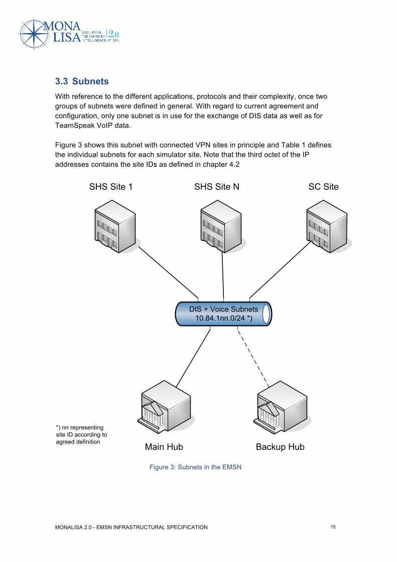
3.3 Subnets With reference to the different applications, protocols and their complexity, once two groups of subnets were defined in general. With regard to current agreement and configuration, only one subnet is in use for the exchange of DIS data as well as for TeamSpeak VoIP data. Figure 3 shows this subnet with connected VPN sites in principle and Table 1 defines the individual subnets for each simulator site. Note that the third octet of the IP addresses contains the site IDs as defined in chapter 4.2
Figure 3: Subnets in the EMSN
SHS Site NSHS Site 1 SC Site
Backup HubMain Hub
DIS + Voice Subnets10.84.1nn.0/24 *)
*) nn representing site ID according to agreed definition
MONALISA 2.0 - EMSN INFRASTRUCTURAL SPECIFICATION
16
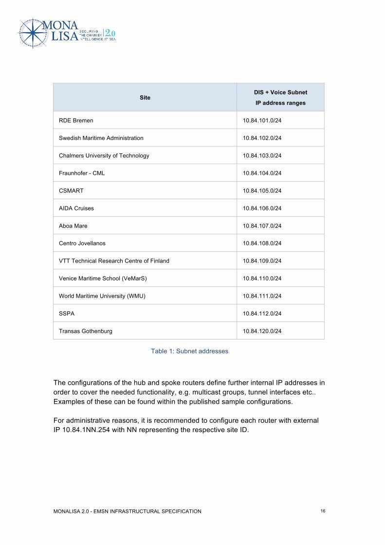
Site DIS + Voice Subnet
IP address ranges
RDE Bremen 10.84.101.0/24
Swedish Maritime Administration 10.84.102.0/24
Chalmers University of Technology 10.84.103.0/24
Fraunhofer - CML 10.84.104.0/24
CSMART 10.84.105.0/24
AIDA Cruises 10.84.106.0/24
Aboa Mare 10.84.107.0/24
Centro Jovellanos 10.84.108.0/24
VTT Technical Research Centre of Finland 10.84.109.0/24
Venice Maritime School (VeMarS) 10.84.110.0/24
World Maritime University (WMU) 10.84.111.0/24
SSPA 10.84.112.0/24
Transas Gothenburg 10.84.120.0/24
Table 1: Subnet addresses
The configurations of the hub and spoke routers define further internal IP addresses in order to cover the needed functionality, e.g. multicast groups, tunnel interfaces etc.. Examples of these can be found within the published sample configurations. For administrative reasons, it is recommended to configure each router with external IP 10.84.1NN.254 with NN representing the respective site ID.
MONALISA 2.0 - EMSN INFRASTRUCTURAL SPECIFICATION
17
3.4 Internet Access Point The Internet access point should provide a static IP address which will be used as the router’s Internet interface. The requirements for the Internet bandwidth are as follows. At spoke sites:
uplink: min. 2 Mbit/s downlink: min. 2 Mbit/s At hub sites:
uplink: min. 25 Mbit/s downlink: min. 5 Mbit/s In the case of DSL connections it is not required to use SDSL. ADSL would be sufficient if the required bandwidths in up and downlink can be achieved.
3.5 Network Devices Following features must be provided by suitable routers:
• VPN
• Multicast over VPN
• Remote management
Recommendation for router devices (refer to /ROUTER/): Cisco 881 Integrated Service Router
3.6 Tools Monitoring and administration of the EMSN is done with assistance of network management tools included in the router delivery. For inspection of network packets the widespread and freely available tool /WIRESHARK/ is used / recommended.
MONALISA 2.0 - EMSN INFRASTRUCTURAL SPECIFICATION
18
4 Distributed Interactive Simulation Cit. [/DIS/], page 1, chapter 1.1 Scope “This standard defines the data messages, known as PDUs that are exchanged on a network between simulation applications. The messages are organized within specified domains called protocol families. The protocol families included in this standard include Entity Information/Interaction, Warfare, Logistics, Simulation Management, Distributed Emission Regeneration, Radio Communications, Entity Management, Minefield, Synthetic Environment, Simulation Management with Reliability, Live Entity Information/Interaction, and Non-Real Time.” For further reading see /DIS/.
4.1 Protocol Data Units In the context of the EMSN only a subset of DIS PDUs have to be supported in order to achieve the EMSN’s goals. The required PDUs are as follows:
• Start / Resume
• Stop / Freeze
• Acknowledge (optional)
• Create Entity (optional)
• Remove Entity (optional)
• Entity State
• Transmitter (used for AIS)
• Signal (used for AIS)
• Collision (optional)
The Simulation Management PDU’s ”Acknowledge”, ”Create Entity” and ”Remove Entity” would be mandatory in case of a centralized Simulation Management according to the DIS-Standard. Actually, each simulator centre has its own internal ”Simulation Management” as part of the respective simulator installation and creates objects according to manufacturer specific implementations. Following the DIS-Standard, the simplest way of entity creation is to start the exchange of respective PDU’s (Cit. [/DIS/], chapter 4.5.5.5.1 Entity creation):

MONALISA 2.0 - EMSN INFRASTRUCTURAL SPECIFICATION
19
”Entities may also enter an exercise without being created by means of the Simulation Management protocols. An entity enters an exercise by exchanging PDUs (Entity State PDUs for example) with other entities in the DIS exercise.” This was agreed upon and is the implemented solution within the EMSN so far. There is no support for Automatic Identification System (AIS) information in DIS so far. For that reason RDE proposes the distribution of AIS information over DIS as described in . “Appendix A: Modelling Automatic Identification System (AIS) on DIS”. For further information about AIS data format see /AIS/ and /NMEA/.

MONALISA 2.0 - EMSN INFRASTRUCTURAL SPECIFICATION
20
4.2 Sites & Applications In DIS exercises entities are distinguished by unique entity identifiers. These identifiers consist of a consecutive entity number assigned by the SHS that owns the entity. In order to make the entity identifier unique the entity number comes together with a site ID and an application ID. Both IDs have to be agreed by all participants before a DIS exercise may start. Site IDs and application IDs are defined as unsigned integers. In the MONALISA context, each simulator site is defined regarding organisational and geographical differentiators and given a unique site ID. Within each simulator site there may be more than one simulation application. A simulation application is according to /DIS/, chapter 3.1 a software application or process “that models all or part of the representation of one or more simulation entities.” Chapter 4.2 further states: “In a DIS exercise, simulation applications may represent one or more entities. The simulation application shall issue PDUs for each of the entities that it simulates.” For an exact association of PDU’s to the issuing application, each simulation application at a defined simulator site shall be given a unique application ID within that site. The following table specifies the site IDs and application IDs as applicable for EMSN.
Simulator site Site Name Site ID
Application ID
RDE Bremen RDE_Bremen 1 1
Swedish Maritime
Administration SMA_Gothenburg 2 1
Chalmers University
of Technology Chalmers_Gothenburg 3 1
Fraunhofer CML Fraunhofer_Hamburg 4 1
CSMART CSMART_Almere 5 1
AIDA Cruises CSMART_Rostock 6 1
Aboa Mare AboaMare_Turku 7 1
Centro Jovellanos CentroJovellanos_Gijon 8 1
VTT Technical Research Centre of Finland VTT_Turku 9 1

MONALISA 2.0 - EMSN INFRASTRUCTURAL SPECIFICATION
21
Venice Maritime School (VeMarS) VeMarS_Venice 10 1
World Maritime University (WMU) WMU_Malmoe 11 1
SSPA SSPA_Gothenburg 12 1
Transas Gothenburg Transas_Gothenburg 20 1
Table 2: Site & application IDs
MONALISA 2.0 - EMSN INFRASTRUCTURAL SPECIFICATION
22
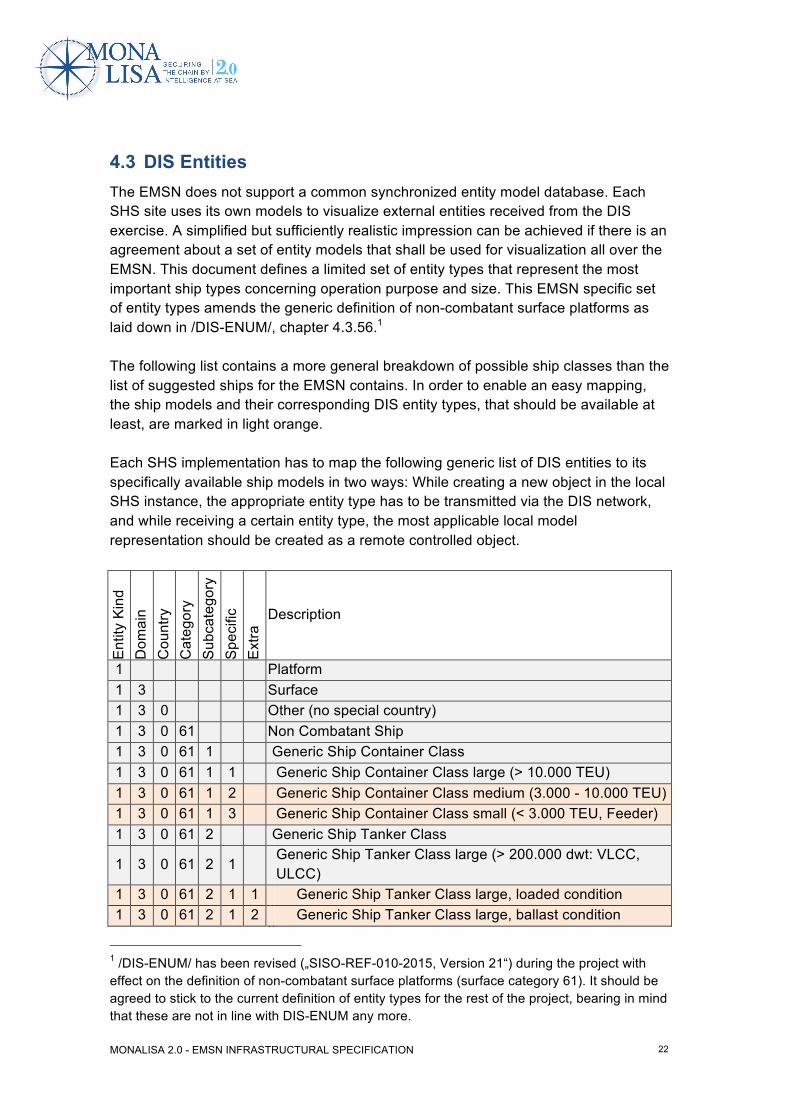
4.3 DIS Entities The EMSN does not support a common synchronized entity model database. Each SHS site uses its own models to visualize external entities received from the DIS exercise. A simplified but sufficiently realistic impression can be achieved if there is an agreement about a set of entity models that shall be used for visualization all over the EMSN. This document defines a limited set of entity types that represent the most important ship types concerning operation purpose and size. This EMSN specific set of entity types amends the generic definition of non-combatant surface platforms as laid down in /DIS-ENUM/, chapter 4.3.56.1 The following list contains a more general breakdown of possible ship classes than the list of suggested ships for the EMSN contains. In order to enable an easy mapping, the ship models and their corresponding DIS entity types, that should be available at least, are marked in light orange. Each SHS implementation has to map the following generic list of DIS entities to its specifically available ship models in two ways: While creating a new object in the local SHS instance, the appropriate entity type has to be transmitted via the DIS network, and while receiving a certain entity type, the most applicable local model representation should be created as a remote controlled object.
Ent
ity K
ind
Dom
ain
Cou
ntry
C
ateg
ory
Sub
cate
gory
S
peci
fic
Ext
ra Description
1 Platform 1 3 Surface 1 3 0 Other (no special country) 1 3 0 61 Non Combatant Ship 1 3 0 61 1 Generic Ship Container Class 1 3 0 61 1 1 Generic Ship Container Class large (> 10.000 TEU) 1 3 0 61 1 2 Generic Ship Container Class medium (3.000 - 10.000 TEU) 1 3 0 61 1 3 Generic Ship Container Class small (< 3.000 TEU, Feeder) 1 3 0 61 2 Generic Ship Tanker Class
1 3 0 61 2 1 Generic Ship Tanker Class large (> 200.000 dwt: VLCC, ULCC)
1 3 0 61 2 1 1 Generic Ship Tanker Class large, loaded condition 1 3 0 61 2 1 2 Generic Ship Tanker Class large, ballast condition
1 /DIS-ENUM/ has been revised („SISO-REF-010-2015, Version 21“) during the project with effect on the definition of non-combatant surface platforms (surface category 61). It should be agreed to stick to the current definition of entity types for the rest of the project, bearing in mind that these are not in line with DIS-ENUM any more.
MONALISA 2.0 - EMSN INFRASTRUCTURAL SPECIFICATION
23
Ent
ity K
ind
Dom
ain
Cou
ntry
C
ateg
ory
Sub
cate
gory
S
peci
fic
Ext
ra Description
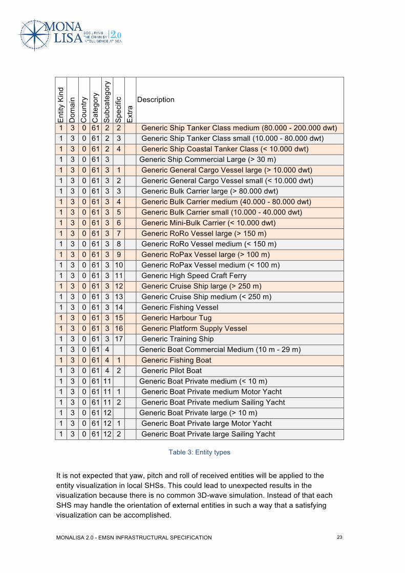
1 3 0 61 2 2 Generic Ship Tanker Class medium (80.000 - 200.000 dwt) 1 3 0 61 2 3 Generic Ship Tanker Class small (10.000 - 80.000 dwt) 1 3 0 61 2 4 Generic Ship Coastal Tanker Class (< 10.000 dwt) 1 3 0 61 3 Generic Ship Commercial Large (> 30 m) 1 3 0 61 3 1 Generic General Cargo Vessel large (> 10.000 dwt) 1 3 0 61 3 2 Generic General Cargo Vessel small (< 10.000 dwt) 1 3 0 61 3 3 Generic Bulk Carrier large (> 80.000 dwt) 1 3 0 61 3 4 Generic Bulk Carrier medium (40.000 - 80.000 dwt) 1 3 0 61 3 5 Generic Bulk Carrier small (10.000 - 40.000 dwt) 1 3 0 61 3 6 Generic Mini-Bulk Carrier (< 10.000 dwt) 1 3 0 61 3 7 Generic RoRo Vessel large (> 150 m) 1 3 0 61 3 8 Generic RoRo Vessel medium (< 150 m) 1 3 0 61 3 9 Generic RoPax Vessel large (> 100 m) 1 3 0 61 3 10 Generic RoPax Vessel medium (< 100 m) 1 3 0 61 3 11 Generic High Speed Craft Ferry 1 3 0 61 3 12 Generic Cruise Ship large (> 250 m) 1 3 0 61 3 13 Generic Cruise Ship medium (< 250 m) 1 3 0 61 3 14 Generic Fishing Vessel 1 3 0 61 3 15 Generic Harbour Tug 1 3 0 61 3 16 Generic Platform Supply Vessel 1 3 0 61 3 17 Generic Training Ship 1 3 0 61 4
Generic Boat Commercial Medium (10 m - 29 m)
1 3 0 61 4 1 Generic Fishing Boat 1 3 0 61 4 2 Generic Pilot Boat 1 3 0 61 11
Generic Boat Private medium (< 10 m)
1 3 0 61 11 1 Generic Boat Private medium Motor Yacht 1 3 0 61 11 2 Generic Boat Private medium Sailing Yacht 1 3 0 61 12
Generic Boat Private large (> 10 m)
1 3 0 61 12 1 Generic Boat Private large Motor Yacht 1 3 0 61 12 2 Generic Boat Private large Sailing Yacht
Table 3: Entity types
It is not expected that yaw, pitch and roll of received entities will be applied to the entity visualization in local SHSs. This could lead to unexpected results in the visualization because there is no common 3D-wave simulation. Instead of that each SHS may handle the orientation of external entities in such a way that a satisfying visualization can be accomplished.

MONALISA 2.0 - EMSN INFRASTRUCTURAL SPECIFICATION
24
5 Voice Communication TeamSpeak (TS), an existing tool for VoIP, will be used for EMSN voice communication needs. It will be setup at each site with purpose to simulate VHF communication. Each site can have several instances of TS to simulate one or more VHF radio per Bridge, SC and Instructor station.
5.1 Simulation of VHF channels TS uses channels to distinguish “rooms”. All clients within the same channel can communicate freely, as on a VHF radio. Setting up a number of channels on the TS server will give participants a possibility to change channel. This must be done on a software panel on the computer display. VHF replica panels will not be used for EMSN.
5.2 Intercom between Instructors By creating specific roles for Instructors, TS can give the Instructors a possibility to communicate within a private group directly to each other.
5.3 System requirements • Windows 2000, XP, 2003, 2008, Vista or 7
• Intel Pentium III, AMD Athlon XP, or any newer CPU (recommended: 800 MHz or faster)
• 128 MB of system memory (recommended: 512 MB or more)
• 50 MB of disk space
• Loudspeakers for watchkeeping
MONALISA 2.0 - EMSN INFRASTRUCTURAL SPECIFICATION
25
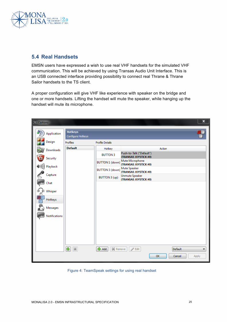
5.4 Real Handsets EMSN users have expressed a wish to use real VHF handsets for the simulated VHF communication. This will be achieved by using Transas Audio Unit Interface. This is an USB connected interface providing possibility to connect real Thrane & Thrane Sailor handsets to the TS client. A proper configuration will give VHF like experience with speaker on the bridge and one or more handsets. Lifting the handset will mute the speaker, while hanging up the handset will mute its microphone.
Figure 4: TeamSpeak settings for using real handset

MONALISA 2.0 - EMSN INFRASTRUCTURAL SPECIFICATION
26
6 Exercises For the schedule and the planned content of exercises refer to /TESTPLAN/.

MONALISA 2.0 - EMSN INFRASTRUCTURAL SPECIFICATION
27
7 Further Requirements Each site has to provide a fixed line number that make it possible to contact the site whenever other means of communication like internet or mobile phone are not available.
MONALISA 2.0 - EMSN INFRASTRUCTURAL SPECIFICATION
28
Appendix A: Modelling Automatic Identification System (AIS) on DIS This chapter shall describe how to distribute and receive AIS data within a network of coupled simulator systems.
General Since AIS communication has not been standardized in DIS yet by introducing specific PDUs or by defining AIS specific enumeration values for generic PDUs, a proposal for distributing NMEA coded AIS messages shall be given here, including all required data used for a high fidelity simulation of transmissions. For the current project, it would be sufficient to just distribute the AIS data. However, for a correct simulation of the transmission, e.g. whether it can be received, more data is required. This includes among other things the origin, frequency, and bandwidth by which the signal is transmitted. Therefore, a correct implementation that realizes these requirements is proposed. The implementation shall be based on the DIS standard IEEE 1278.1-1995 (“IEEE Standard for Distributed Interactive Simulation – Application Protocol”) and its supplement IEEE 1278.1a-1998.
Transmitter PDU The Transmitter PDU is defined in IEEE 1278.1-1995, Section 5.3.8.1. It shall represent the transmitting device on board of a platform and define the device type as well as the device state and the signal’s transmission attributes (frequency, bandwidth, transmitted power, etc.). Since AIS is specified to send signals on two parallel frequency channels (161.975 MHz and 162.025 MHz, cf. ITU-R M.1371-1), for each correctly installed transmitter two Transmitter PDUs must be sent, one for each frequency. The Transmitter PDU shall at least contain valid data within the following fields (additional to the common PDU Header):
- Entity ID (IEEE 1278.1-1995, Section 5.3.8.1.b): Identification of the entity that is the source of the transmission.
- Radio ID (IEEE 1278.1-1995, Section 5.3.8.1.c): Identification of the radio within an entity, starting with Radio ID 1. (Remark: Transmitters and Receiver share a pool of IDs.)
MONALISA 2.0 - EMSN INFRASTRUCTURAL SPECIFICATION
29
- Radio Entity Type (IEEE 1278.1-1995, Section 5.3.8.1.c): Identification of the radio type that is simulated. This field contains the parameters Entity Kind, Domain, Country, Category, Nomenclature Version and Nomenclature. The last two of these parameters are very specific and shall be allowed to be set to 0 (i.e. Other). The following information is based on the standard contained in the document SISO-REF-010-2011.1.
o Entity Kind shall be 7 since this defines a radio.
o Domain shall be the same as the operating domain of the host entity.
o Country shall define the radio’s country of origin.
o Category shall identify the radio as an AIS transmitter. Since there is no specific value defined for an AIS transmitter, this value shall be set to 0 (i.e. Other).
- Transmit State (IEEE 1278.1-1995, Section 5.3.8.1.e): This field shall specify the state of the radio (off, powered but not transmitting, or powered and transmitting; cf. SISO-REF-010-2011.1, Section 9.1.2)
- Antenna Location (IEEE 1278.1-1995, Section 5.3.8.1.g): This item actually defines two positions that shall be given. The first one (Antenna Location) shall contain the position of the antenna’s radiating part in world coordinates while the second one (Relative Antenna Location) shall contain the position of the antenna’s radiating part within the entity-relative coordinate system.
- Frequency (IEEE 1278.1-1995, Section 5.3.8.1.j): This field shall contain the centre frequency that is used by this radio for transmissions (in units of hertz).
- Transmit Frequency Bandwidth (IEEE 1278.1-1995, Section 5.3.8.1.k): This field shall identify the radio’s bandpass.
- Power (IEEE 1278.1-1995, Section 5.3.8.1.l): This field shall specify the average power being transmitted (in units of decibel-milliwatts).
Receiver PDU The Receiver PDU is defined in IEEE 1278.1-1995, Section 5.3.8.3. It shall represent the receiving device on board of a platform. Since the receiver device is not required for distributing data on DIS and the receiving application must not contain any radio transmission simulation but instead just process received PDUs, it is not required to send Receiver PDUs. Still, for a correct simulation the device’s state should be distributed. The Receiver PDU shall at least contain valid data within the following fields (additional to the common PDU Header):
- Entity ID (IEEE 1278.1-1995, Section 5.3.8.3.b): Identification of the entity that can receive radio transmissions.
MONALISA 2.0 - EMSN INFRASTRUCTURAL SPECIFICATION
30
- Radio ID (IEEE 1278.1-1995, Section 5.3.8.3.c): Identification of the radio within an entity, starting with Radio ID 1. (Remark: Transmitters and Receiver share a pool of IDs.)
- Receiver State (IEEE 1278.1-1995, Section 5.3.8.3.d): This field shall specify the state of the radio (off, on but not receiving, or on and receiving; cf. SISO-REF-010-2011.1, Section 9.2)
Signal PDU The Signal PDU is defined in IEEE 1278.1-1995, Section 5.3.8.2. It shall represent a single radio transmission, i.e. a transmitted AIS message. It must refer to the transmitter which is the source of the signal. Since there must be two transmitters for a correctly installed AIS system as mentioned above, each AIS message shall be sent twice (once per transmitter). For transmitting NMEA-coded AIS messages, the Signal PDU is set to contain application-specific data. In the Data field a unique identifier for the application (i.e. AIS) is contained which is followed by the actual AIS data. Therefore, the Signal PDU shall at least contain valid data within the following fields (additional to the common PDU Header):
- Entity ID (IEEE 1278.1-1995, Section 5.3.8.2.b): Identification of the entity that is the source of the transmission.
- Radio ID (IEEE 1278.1-1995, Section 5.3.8.2.c): This field shall identify the radio that is the source of this transmission. It must refer to a particular radio within a given entity. Entity ID and Radio ID together uniquely identify a particular radio within a simulation exercise and refer to the Transmitter PDU.
- Encoding Scheme (IEEE 1278.1-1995, Section 5.3.8.2.d): This field shall specify the encoding used in the Data field of this PDU. It actually contains two values:
o Encoding Class (the two most significant bits; Bits 14 - 15): Since application-specific data is transmitted, this field shall be 2 (cf. SISO-REF-010-2011.1, Section 9.1.8).
o Encoding Type (the 14 least significant bits; Bits 0 - 13): Shall be 0 because the Encoding Class is not encoded audio and the TDL type is 0.
- TDL Type (IEEE 1278.1-1995, Section 5.3.8.2.e): This field shall be 0 since the transmitted data is not a TDL message (cf. SISO-REF-010-2011.1, Section 9.1.11).
- Sample Rate (IEEE 1278.1-1995, Section 5.3.8.2.f): This field shall specify the data rate in bits per second.
MONALISA 2.0 - EMSN INFRASTRUCTURAL SPECIFICATION
31
- Data Length (IEEE 1278.1-1995, Section 5.3.8.2.g): This field shall specify the number of bits of digital data being sent in this Signal PDU. This field must be 32-bits larger than the actually transmitted data because the first 32-bits of the Data field must be used to specify the User Protocol ID (cf. IEEE 1278.1-1995, Section 5.3.8.2.i) as defined below.
- Samples (IEEE 1278.1-1995, Section 5.3.8.2.h): This field shall be 0 since the transmitted data is not encoded audio.
- Data (IEEE 1278.1-1995, Section 5.3.8.2.i): This field must contain the User Protocol ID within its first 32-bits. This ID shall identify the transmitted data as being an AIS message and shall be set to 1371 (cf. SISO-REF-010-00v20-0, Section 8.2.3). The remainder of this field shall contain the actual NMEA-coded AIS message.

MONALISA 2.0 - EMSN INFRASTRUCTURAL SPECIFICATION
32
39 partners from 10 countries taking maritime transport into the digital age
By designing and demonstrating innovative use of ICT solutions
MONALISA 2.0 will provide the route to improved
SAFETY - ENVIRONMENT - EFFICIENCY
Swedish Maritime Administration ◦ LFV - Air Navigation Services of Sweden ◦ SSPA ◦ Viktoria Swedish ICT ◦ Transas ◦ Carmenta ◦ Chalmers University of Technology ◦
World Maritime University ◦ The Swedish Meteorological and Hydrological Institute ◦ Danish Maritime Authority ◦ Danish Meteorological Institute ◦ GateHouse ◦ Navicon ◦
Novia University of Applied Sciences ◦ DLR ◦ Fraunhofer ◦ Jeppesen ◦ Rheinmetall ◦ Carnival Corp. ◦ Italian Ministry of Transport ◦ RINA Services ◦ D’Appolonia ◦ Port of
Livorno ◦ IB SRL ◦ Martec SPA ◦ Ergoproject ◦ University of Genua ◦ VEMARS ◦ SASEMAR ◦ Ferri Industries ◦ Valencia Port Authority ◦ Valencia Port Foundation ◦
CIMNE ◦ Corporacion Maritima ◦ Technical University of Madrid ◦ University of Catalonia ◦ Technical University of Athens ◦ MARSEC-XL ◦ Norwegian Coastal
Administration
www.monalisaproject.eu


![MonaLisa - arXiv · 2018-10-27 · arXiv:0801.2501v1 [physics.data-an] 16 Jan 2008 MonaLisa thestochasticviewandfractalityincolorspace PouriaPedrama,b∗,G.R.Jafari …](https://img.pdfslide.us/doc/110x75/5f1f365fd5cb3a20ab6a73c6/monalisa-arxiv-2018-10-27-arxiv08012501v1-16-jan-2008-monalisa-thestochasticviewandfractalityincolorspace.jpg)