Embed Size (px)
Citation preview
Source of Acquisition NASA Marshall Space Flight C a m
Momentum Transfer in a Spinning Fuel Tank Filled with Xenon
John Peugeot* and Daniel J. Dorney' NASA Marshall Space Flight Center
Propellant Fluids Delivery Branch MSFC, AI, 35812
ABSTRACT
Transient spin-up and spin-down flows inside of spacecraft fuel tanks need to be analyzed in order to properly design spacecraft control systems. Knowledge of the characteristics of angular momentum transfer to and from the fuel is used to size the de-spin mechanism that places the spacecraft in a controllable in-orbit state.
In previous studies, several analytical models of the spin-up process were developed. However, none have accurately predicted all of the flow dynamics. Several studies have also been conducted using Navier-Stokes based methods. These approaches have been much more successful at simulating the dynamic processes in a cylindrical container, but have not addressed the issue of momentum transfer.
In the current study, the spin-up and spin-down of a fuel tank filled with gaseous xenon has been investigated using a three-dimensional unsteady Navier-Stokes code. Primary interests have been concentrated on the spin-uphpin-down time constants and the initial torque imparted on the system. Additional focus was given to the relationship between the dominant flow dynamics and the trends in momentum transfer. Through the simulation of both a cylindrical and a spherical t a a , it was revealed that the transfer of angular momentum is nonlinear at early times and tends toward a linear pattern at later times. Further investigation suggests that the nonlinear spin up is controlled by the turbulent transport of momentum, while the linear phase is controlled by a Coriolis driven (Ekman) flow along the outer wall. These results indicate that the spin- up and spin-down processes occur more quickly
in tanks with curved surfaces than those with defined top, bottom, and side walls. The results also provide insights for the design of spacecraft de-spin mechanisms.
NOMENCLATURE
H Angular momentum P Pressure t Time T Temperature Re Reynolds number V Kinematic viscosity P Density sz Angular velocity
INTRODUCTION
The problem of spin-up from rest is well suited to computational analysis because the internal flow dynamics have been found to be non-linear, and cannot be easily visualized or measured experimentally [ 11. The analysis of spin-up of an incompressible fluid in a cylindrical tank has been performed in previous studies [l-31. Several of these investigations have successfully implemented Navier-Stokes based methods, demonstrating significant improvements over the results obtain from known analytical methods. Hyun, et al. concluded in their work [3] that the spin up process is controlled in the following manner. Immediately after impulsive start, viscous diffusion dominates spin up. Once, the Ekman flux is established, the spin up is dominated by nonlinear radial advection. Eventually, for t/h>0.5, the strength of the
* Aerospace Engineer, Member AIAA. + Aerospace Engineer, Associate Fellow A M .
1
https://ntrs.nasa.gov/search.jsp?R=20060050749 2019-08-20T06:52:41+00:00Z
nonlinearity diminishes and the linear Coriolis force dominates.
In the current study, the spin-uphpin-down time constants and the initial torque imparted on the system are of primary interest. Additionally, the flow dynamics which control the spin-up are also examined. Previous work from Greenspan [2], suggests four areas of particular interest. Figure 1 outlines these areas as: (1) the region in front of the shear front, which is at rest, (2) the region behind the front, which is in motion, (3) the Ekman layer which is a result of Coriolis forces, and (4) which is the reverse flow zone that is a product of the Ekman layer pumping fluid from region 1 to region 2.
Figure 1: General flow pattern during spin up of a cylindrical tank: (1) region in front of the shear front, (2) region behind the shear front, (3) Ekman layer, (4) reverse flow zone
In the current study, two geometries were analyzed; a cylindrical tank, and an oblate spheroid tank. Both cases were impulsively started from rest and spun up to a constant rate of rotation and then spun back down to rest. The flow conditions for temperature, pressure, rotation rate, etc. were based on estimated conditions of a recent spacecraft mission. The investigations were performed using a three- dimensional unsteady Navier-Stokes code. This code is particularly suited for rotating components and has been highly successful at predicting unsteady phenomena in turbomachinery applications.
NUMERICAL PROCEDURE
The general code structure is based on a well- established compressible, 3-D, unsteady turbomachinery flow code [4]. It employs a system of overset 0-grids and H-grids, with the values on the 0-H boundaries being updated each time step by bilinear interpolation from the adjacent grid. The inviscid fluxes are third-order spatially accurate and are calculated using Roe’s scheme [5]. The viscous fluxes are calculated using second-order accurate central differences, and the code is second-order accurate in time. A modified Baldwin-Lomax turbulence model is used for turbulence closure [6].
The code contains two options for the determination of fluid properties. The first option is based on the equations of state, thermodynamic departure functions and corresponding state principles constructed by Oefelein [7]. The second option is based on splines generated from the NIST Tables [8], and is computationally more efficient. The code currently contains fluid property routines (both gaseous and liquid) for water, hydrogen, oxygen, nitrogen, RP-1, methane, carbon monoxide and xenon.
Comuutational Grids
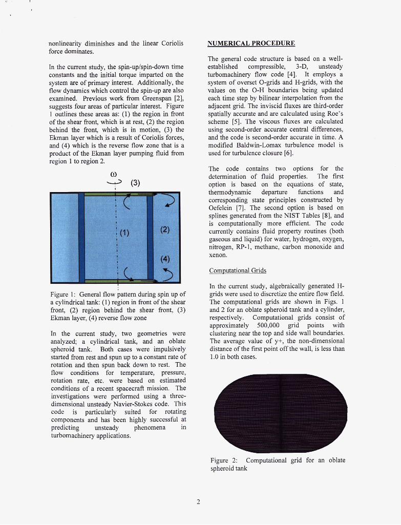
In the current study, algebraically generated H- grids were used to discretize the entire flow field. The computational grids are shown in Figs. 1 and 2 for an oblate spheroid tank and a cylinder, respectively. Computational grids consist of approximately 500,000 grid points with clustering near the top and side wall boundaries. The average value of y+, the non-dimensional distance of the first point off the wall, is less than 1 .O in both cases.
€ A Figure 2: spheroid tank
Computational grid for an oblate
r-
Figure 3: Computational cylinder
Boundarv Conditions
grid for an oblate
At solid surfaces the relative velocity is set to zero, the normal derivative of the pressure is set to zero, and the surfaces are assumed to be adiabatic.
A detailed description of the code/algorithm development, as well as its application to several turbine and pump test cases, is presented in Refs. 9 and 10.
NUMERICAL SIMULATIONS
The numerical simulations were performed for both geometries using the following flow conditions:
T = 2 5 C P = 1250 psi p = 1667 kg/m3 v = 5.204 x lom8 m2/s R=60rpm Re =2.3 x lo7
The flow is essentially incompressible, and the pressure and temperature (thus the density) vary little throughout the spin-up process. The tanks were impulsively spun up from rest and the subsequent gas spin up was observed. Likewise, the rotation of the tanks was. impulsively stopped, and the tanks were spun down to rest to observe the gas dynamics phenomena.
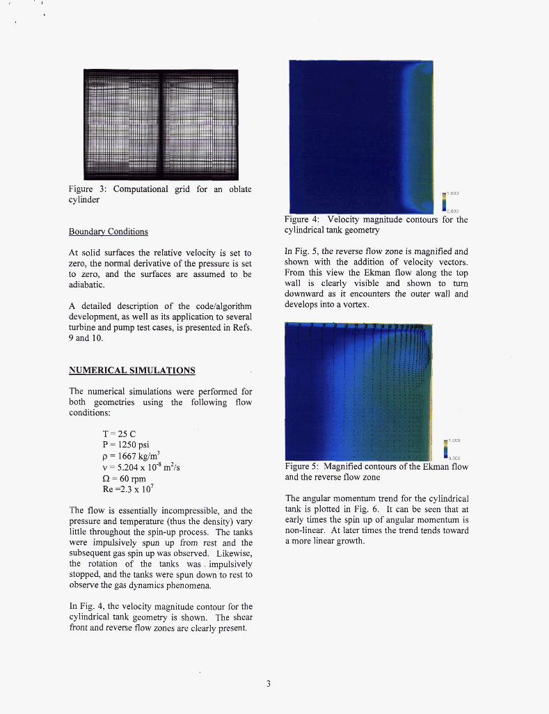
Figure 4: Velocity magnitude contours for the cylindrical tank geometry
In Fig. 5, the reverse flow zone is magnified and shown with the addition of velocity vectors. From this view the Ekman flow along the top wall is clearly visible and shown to turn downward as it encounters the outer wall and develops into a vortex.
1.000
0.000
I L 5 g U . W 4. I I I u p 1 1 1 1 W u W V U L V L U I . "I U I Y Jkman flow and the reverse flow zone
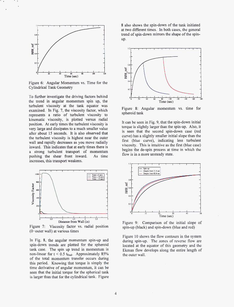
The angular momentum trend for the cylindrical tank is plotted in Fig. 6. It can be seen that at early times the spin up of angular momentum is non-linear. At later times the trend tends toward a more linear growth.
In Fig. 4, the velocity magnitude contour for the cylindrical tank geometry is shown. The shear front and reverse flow zones are clearly present.
3
1
t/ 1 OO v a0 40 m 80 io0 la,
Time (sec)
Figure 6: Angular Momentum vs. Time for the Cylindrical Tank Geometry
To further investigate the driving factors behind the trend in angular momentum spin up, the turbulent viscosity at the tank equator was examined. In Fig. 7, the viscosity factor, which represents a ratio of turbulent viscosity to kinematic viscosity, is plotted versus radial position. At early times the turbulent viscosity is very large and dissipates to a much smaller value after about 15 seconds. It is also observed that the turbulent viscosity is highest near the outer wall and rapidly decreases as you move radially inward. This indicates that at early times there is a strong turbulent transport of momentum pushing the shear front inward. As time increases, this transport weakens.
0 O J I .5 2.5 3
Distance from Wall (in) Figure 7: (O=outer wall) at various times
Viscosity factor vs. radial position
In Fig. 8, the angular momentum spin-up and spin-down trends are plotted for the spheroid tank case. The spin up trend in momentum is non-linear for t < 0.5 tfinal. Approximately 85% of the total momentum transfer occurs during this period. Knowing that torque is simply the time derivative of angular momentum, it can be seen that the initial torque for the spherical tank is larger than that for the cylindrical tank. Figure
8 also shows the spin-down of the tank initiated at two different times. In both cases, the general trend of spin-down mirrors the shape of the spin- UP.
Figure 8: Angular momentum vs. time for spheroid tank
It can be seen in Fig. 9, that the spin-down initial torque is slightly larger than the spin-up. Also, it is seen that the second spin-down case (red curve) has a slightly smaller initial slope than the first (blue curve), indicating less turbulent viscosity. This is intuitive as the first (blue case) begins the de-spin process at time in which the flow is in a more unsteady state.
o'21L---J OO 20 M Jo M
Time (sec)
Figure 9: spin-up (black) and spin-down (blue and red)
Comparison of the initial slope of
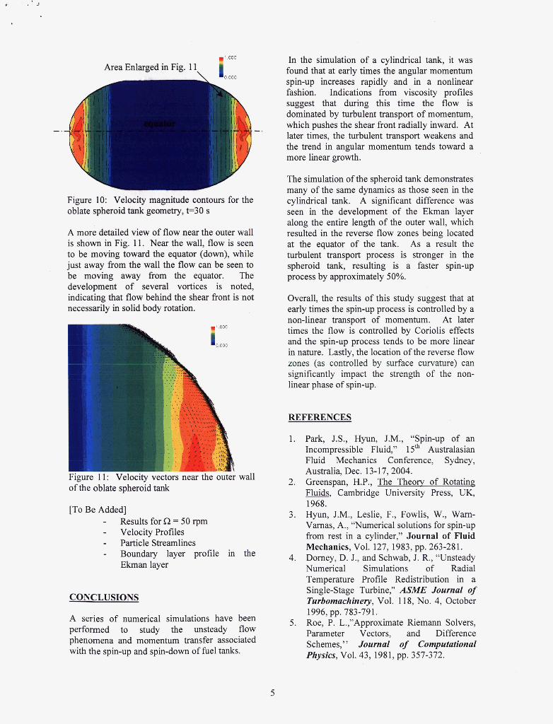
Figure 10 shows the flow contours in the system during spin-up. The zones of reverse flow are located at the equator of this geometry and the Ekman flow develops along the entire length of the outer wall.
~ 1 . 0 0 0
0.000
Area Enlarged in Fig. 11
L .
A .
Figure 10: Velocity magnitude contours for the oblate spheroid tank geometry, t=30 s
A more detailed view of flow near the outer wall is shown in Fig. 11. Near the wall, flow is seen to be moving toward the equator (down), while just away from the wall the flow can be seen to be moving away from the equator. The development of several vortices is noted, indicating that flow behind the shear front is not necessarily in solid body rotation.
In the simulation of a cylindrical tank, it was found that at early times the angular momentum spin-up increases rapidly and in a nonlinear fashion. Indications from viscosity profiles suggest that during this time the flow is dominated by turbulent transport of momentum, which pushes the shear front radially inward. At later times, the turbulent transport weakens and the trend in angular momentum tends toward a more linear growth.
I-’
The simulation of the spheroid tank demonstrates many of the same dynamics as those seen in the cylindrical tank. A significant difference was seen in the development of the Ekman layer along the entire length of the outer wall, which resulted in the reverse flow zones being located at the equator of the tank. As a result the turbulent transport process is stronger in the spheroid tank, resulting is a faster spin-up process by approximately 50%.
Overall, the results of this study suggest that at early times the spin-up process is controlled by a non-linear transport of momentum. At later times the flow is controlled by Coriolis effects and the spin-up process tends to be more linear in nature. Lastly, the location of the reverse flow zones (as controlled by surf-ace curvature) can significantly impact the strength of the non- linear phase of spin-up.
1.000
I 0.000
REFERENCES
r ~gurt: I I: V GlUclIy ver;wrs near the outer wall of the oblate spheroid tank
[To Be Added] - - Velocity Profiles - Particle Streamlines - Boundary layer profile in the
Results for R = 50 rpm
Ekman layer
CONCLUSIONS
A series of numerical simulations have been performed to study the unsteady flow phenomena and momentum transfer associated with the spin-up and spin-down of fuel tanks.
1.
2.
3.
4.
5 .
Park, J.S., Hyun, J.M., “Spin-up of an Incompressible Fluid,” 15* Australasian Fluid Mechanics Conference, Sydney, Australia, Dec. 13-17,2004. Greenspan, H.P., The Theory of Rotating Fluids, Cambridge University Press, UK, 1968. Hyun, J.M., Leslie, F., Fowlis, W., Warn- Varnas, A., “Numerical solutions for spin-up from rest in a cylinder,” Journal of Fluid Mechanics, Vol. 127, 1983, pp. 263-281. Dorney, D. J., and Schwab, J. R., “Unsteady Numerical Simulations of Radial Temperature Profile Redistribution in a Single-Stage Turbine,“ ASME Journal of Turbomachinery, Vol. 11 8, No. 4, October
Roe, P. L.,”Approximate Riemann Solvers, Parameter Vectors, and Difference Schemes,’ ’ Journal of Computational Physics, Vol. 43, 1981, pp. 357-372.
1996, pp. 783-791.
6.
7.
8. 9.
10.
Baldwin, B. S., and Lomax, H., "Thin Layer Approximation and Algebraic Model for Separated Turbulent Flow," AIAA Paper 78-257, Huntsville, AL, January, 1978. Oefelein, J. C., Sandia Corporation, Livermore, CAY Private Communication, December, 2002. http://webbook.nist.aov/chemistry/fluid Sondak, D. L. and Domey, D. J., "General Equation Set Solver for Compressible and Incompressible Turbomachinery Flows," AIAA 2003-4420, 39th AWASMEISAEIASEE Joint Propulsion Conference and Exhibit, Huntsville, AL,
Merkle, C. L., Venkateswaran, S., Domey, D. J., and Sondak, D. L., "A Generalized Fluid Formulation for Turbomachinery Computations," AIAA 2003-3999, 33rd AIAA Fluid Dynamics Conference and Exhibit, Orlando, FLY June 23-26,2003
July 20-23,2003.
6


![arXiv:1810.12400v2 [gr-qc] 6 Mar 2019 · 2 and angular momentum of gravastars may lead to instability for some rapidly spinning con gurations [42], but other spinning con gurations](https://img.pdfslide.us/doc/110x75/5e0700aeae595933011963f6/arxiv181012400v2-gr-qc-6-mar-2019-2-and-angular-momentum-of-gravastars-may-lead.jpg)


![[New Symmetry Issue] Xenon, Xenon Everywhere; A Measurement to Watch](https://img.pdfslide.us/doc/110x75/563db844550346aa9a9221ed/new-symmetry-issue-xenon-xenon-everywhere-a-measurement-to-watch.jpg)