Embed Size (px)
Citation preview
Momentum Principles
Arturo S. Leon, PhD, PE, D.WRE

● Open channel flow with complex internal flow patterns can have high energy loss, the nature of which is difficult to estimate.
● In cases of complex internal flow patterns, the energy equation cannot be applied to relate flow parameters. In these cases, the momentum equation with suitable assumptions is recommended.
● For instance, the application of the momentum equation to hydraulic jumps yields meaningful results.
Momentum Equation

● Occurs when a supercritical flow meets a subcritical flow.
● Jump consists of a steep change in the water-surface elevation with a reverse flow roller on the major part.
● Roller entrains considerable quantity of air and the surface has white, frothy and choppy appearance.
Hydraulic Jump
See Video: https://www.youtube.com/watch?v=XsYgODmmiAM
Momentum function
Where: hc = centroid of the area A, Fp = pressure force at the control surface
For steady flow and horizontal channel

Momentum function (Cont.)

Momentum function (M) for various channels

Hydraulic jump in a horizontal, rectangular channel
Hydraulic Jump in a rectangular channel

Hydraulic Jump in a rectangular channel (Cont.)

Hydraulic Jump in a rectangular channel (Cont.)
Belanger momentum equation

Hydraulic Jump in a rectangular channel (Cont.)
Fp1
Fp2
Jump Losses:
where: EL = E1 – E2 (Head loss)
In terms of F2 (Subcritical Froude number)

Classification of Hydraulic Jumps
Source: Munson, Young and Okiishi's Fundamentals of Fluid Mechanics, 8th Edition

Hydraulic Jump Variations(a) jump caused by a change in channel slope,(b) submerged jump

Example:Under appropriate conditions, water flowing from a faucet, onto a flat plate, and over the edge of the plate can produce a circular hydraulic jump as shown in the figure below. Consider a situation where a jump forms 3.0 in from the center of the plate with depths upstream and downstream of the jump of 0.05 in and 0.20 in, respectively. Determine the flow rate from the faucet.


Water enters a reach of a rectangular channel where y1 = 0.5 m, b = 7.5 m, and Q = 20 m3/s. It is desired that a hydraulic jump occur upstream (location 2) of the sill and on the sill critical conditions exist (location 3). Other than across the jump, losses can be neglected. Determine the following:(a) Depths at locations 2 and 3(b) Required height of the sill, h(c) Resultant force acting on the sill(d) Sketch the water surface and energy grade line.
Example:


Surges
A tidal bore in Morecambe Bay, the United Kingdom
Video of a tidal bore in Chinahttps://www.youtube.com/watch?v=axAxtsyHreQ
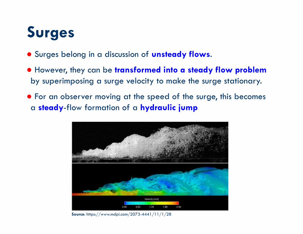
● Surges belong in a discussion of unsteady flows.
● However, they can be transformed into a steady flow problem by superimposing a surge velocity to make the surge stationary.
● For an observer moving at the speed of the surge, this becomes a steady-flow formation of a hydraulic jump
Surges
Source: https://www.mdpi.com/2073-4441/11/1/28

ContinuityStationary jump:
Moving jump:
Surges in rectangular channels

Surges (cont.)
Momentum
Stationary jump:
Moving jump:


Example of Application: A 2m wide rectangular channel carries a discharge of 1 m3/s at a flow depth of 1m. A sluice gate located in the channel is suddenly lowered and it is desired to produce a 0.1m high surge upstream of the gate. Find the velocity of the surge and the flow velocity at a section after the surge has passed. Assume a frictionless and horizontal channel.
Negative surge
Positivesurge
gate

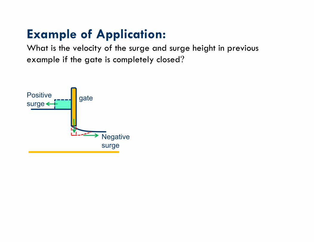
Example of Application: What is the velocity of the surge and surge height in previous example if the gate is completely closed?
Negative surge
Positivesurge
gate

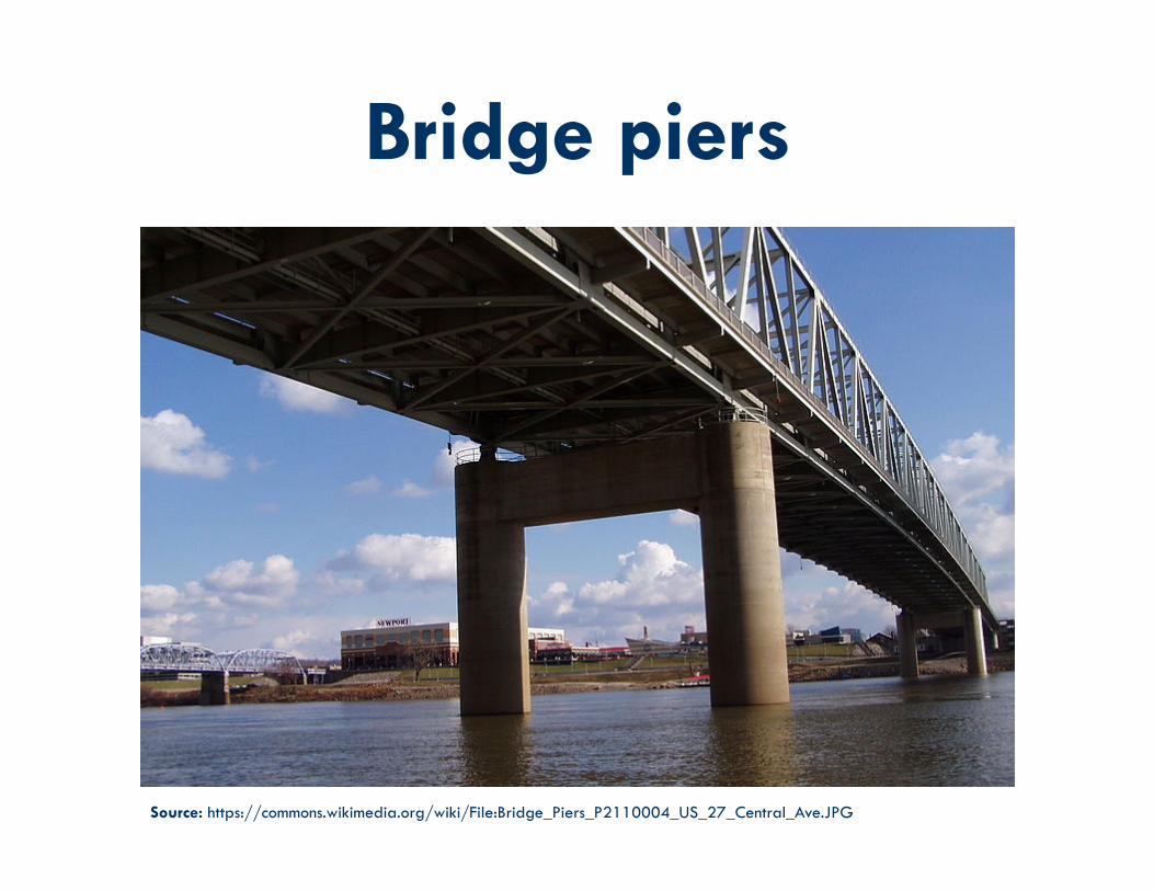
Bridge piers
Source: https://commons.wikimedia.org/wiki/File:Bridge_Piers_P2110004_US_27_Central_Ave.JPG

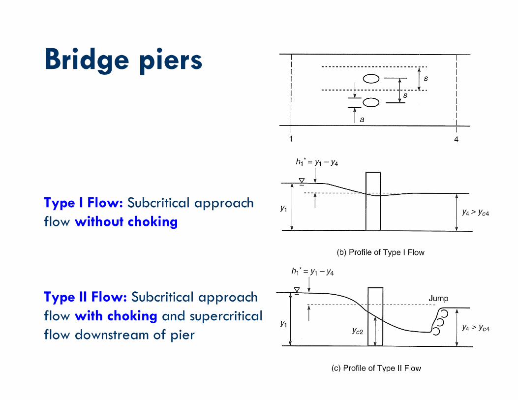
● Obstruction caused by bridge piers in subcritical flows leads to backwater effects upstream and can even cause choking.
● Two types of flow.
● Type I flow: The depth decreases when passing through the constriction with the flow remaining subcritical.
● Type II flow: choking occurs with critical depth existing in the constriction
Bridge piers
Source: https://engineeringmaster.in/2017/04/05/how-bridges-are-built-over-water/
Bridge piers
Type I Flow: Subcritical approach flow without choking
Type II Flow: Subcritical approach flow with choking and supercritical flow downstream of pier
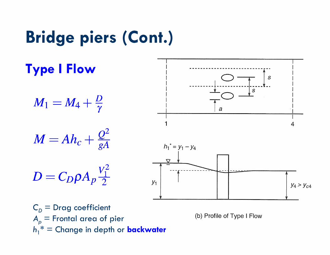
Bridge piers (Cont.)
Type I Flow
CD = Drag coefficientAp = Frontal area of pierh1* = Change in depth or backwater

Bridge piers For a rectangular channel:


Downstream Froude Number, F4
Solution for backwater caused by bridge piers in Type I flow

Example of applicationFor a river flow between bridge piers 3 m in diameter with a spacing of 20 m, determine the backwater using the momentum method if the downstream depth is 4.0 m and the downstream velocity is 1.9 m/s. Assume a drag coefficient of 2.0 for the bridge piers.